EP3610980B1 - Method for manufacturing metal product, and metal product - Google Patents
Method for manufacturing metal product, and metal product Download PDFInfo
- Publication number
- EP3610980B1 EP3610980B1 EP18783821.4A EP18783821A EP3610980B1 EP 3610980 B1 EP3610980 B1 EP 3610980B1 EP 18783821 A EP18783821 A EP 18783821A EP 3610980 B1 EP3610980 B1 EP 3610980B1
- Authority
- EP
- European Patent Office
- Prior art keywords
- marking
- laser beam
- base region
- base
- identification code
- Prior art date
- Legal status (The legal status is an assumption and is not a legal conclusion. Google has not performed a legal analysis and makes no representation as to the accuracy of the status listed.)
- Active
Links
Images







Classifications
-
- B—PERFORMING OPERATIONS; TRANSPORTING
- B23—MACHINE TOOLS; METAL-WORKING NOT OTHERWISE PROVIDED FOR
- B23K—SOLDERING OR UNSOLDERING; WELDING; CLADDING OR PLATING BY SOLDERING OR WELDING; CUTTING BY APPLYING HEAT LOCALLY, e.g. FLAME CUTTING; WORKING BY LASER BEAM
- B23K26/00—Working by laser beam, e.g. welding, cutting or boring
- B23K26/36—Removing material
- B23K26/362—Laser etching
- B23K26/364—Laser etching for making a groove or trench, e.g. for scribing a break initiation groove
-
- B—PERFORMING OPERATIONS; TRANSPORTING
- B41—PRINTING; LINING MACHINES; TYPEWRITERS; STAMPS
- B41M—PRINTING, DUPLICATING, MARKING, OR COPYING PROCESSES; COLOUR PRINTING
- B41M5/00—Duplicating or marking methods; Sheet materials for use therein
- B41M5/24—Ablative recording, e.g. by burning marks; Spark recording
-
- B—PERFORMING OPERATIONS; TRANSPORTING
- B23—MACHINE TOOLS; METAL-WORKING NOT OTHERWISE PROVIDED FOR
- B23K—SOLDERING OR UNSOLDERING; WELDING; CLADDING OR PLATING BY SOLDERING OR WELDING; CUTTING BY APPLYING HEAT LOCALLY, e.g. FLAME CUTTING; WORKING BY LASER BEAM
- B23K26/00—Working by laser beam, e.g. welding, cutting or boring
- B23K26/08—Devices involving relative movement between laser beam and workpiece
- B23K26/082—Scanning systems, i.e. devices involving movement of the laser beam relative to the laser head
-
- B—PERFORMING OPERATIONS; TRANSPORTING
- B23—MACHINE TOOLS; METAL-WORKING NOT OTHERWISE PROVIDED FOR
- B23K—SOLDERING OR UNSOLDERING; WELDING; CLADDING OR PLATING BY SOLDERING OR WELDING; CUTTING BY APPLYING HEAT LOCALLY, e.g. FLAME CUTTING; WORKING BY LASER BEAM
- B23K26/00—Working by laser beam, e.g. welding, cutting or boring
- B23K26/36—Removing material
- B23K26/362—Laser etching
-
- B—PERFORMING OPERATIONS; TRANSPORTING
- B23—MACHINE TOOLS; METAL-WORKING NOT OTHERWISE PROVIDED FOR
- B23K—SOLDERING OR UNSOLDERING; WELDING; CLADDING OR PLATING BY SOLDERING OR WELDING; CUTTING BY APPLYING HEAT LOCALLY, e.g. FLAME CUTTING; WORKING BY LASER BEAM
- B23K26/00—Working by laser beam, e.g. welding, cutting or boring
- B23K26/70—Auxiliary operations or equipment
- B23K26/702—Auxiliary equipment
-
- B—PERFORMING OPERATIONS; TRANSPORTING
- B41—PRINTING; LINING MACHINES; TYPEWRITERS; STAMPS
- B41M—PRINTING, DUPLICATING, MARKING, OR COPYING PROCESSES; COLOUR PRINTING
- B41M5/00—Duplicating or marking methods; Sheet materials for use therein
- B41M5/26—Thermography ; Marking by high energetic means, e.g. laser otherwise than by burning, and characterised by the material used
- B41M5/262—Thermography ; Marking by high energetic means, e.g. laser otherwise than by burning, and characterised by the material used recording or marking of inorganic surfaces or materials, e.g. glass, metal, or ceramics
-
- G—PHYSICS
- G06—COMPUTING OR CALCULATING; COUNTING
- G06K—GRAPHICAL DATA READING; PRESENTATION OF DATA; RECORD CARRIERS; HANDLING RECORD CARRIERS
- G06K1/00—Methods or arrangements for marking the record carrier in digital fashion
- G06K1/12—Methods or arrangements for marking the record carrier in digital fashion otherwise than by punching
- G06K1/128—Methods or arrangements for marking the record carrier in digital fashion otherwise than by punching by electric registration, e.g. electrolytic, spark erosion
-
- G—PHYSICS
- G06—COMPUTING OR CALCULATING; COUNTING
- G06K—GRAPHICAL DATA READING; PRESENTATION OF DATA; RECORD CARRIERS; HANDLING RECORD CARRIERS
- G06K19/00—Record carriers for use with machines and with at least a part designed to carry digital markings
- G06K19/06—Record carriers for use with machines and with at least a part designed to carry digital markings characterised by the kind of the digital marking, e.g. shape, nature, code
- G06K19/06009—Record carriers for use with machines and with at least a part designed to carry digital markings characterised by the kind of the digital marking, e.g. shape, nature, code with optically detectable marking
- G06K19/06037—Record carriers for use with machines and with at least a part designed to carry digital markings characterised by the kind of the digital marking, e.g. shape, nature, code with optically detectable marking multi-dimensional coding
-
- G—PHYSICS
- G06—COMPUTING OR CALCULATING; COUNTING
- G06K—GRAPHICAL DATA READING; PRESENTATION OF DATA; RECORD CARRIERS; HANDLING RECORD CARRIERS
- G06K19/00—Record carriers for use with machines and with at least a part designed to carry digital markings
- G06K19/06—Record carriers for use with machines and with at least a part designed to carry digital markings characterised by the kind of the digital marking, e.g. shape, nature, code
- G06K19/06009—Record carriers for use with machines and with at least a part designed to carry digital markings characterised by the kind of the digital marking, e.g. shape, nature, code with optically detectable marking
- G06K19/06046—Constructional details
- G06K19/06121—Constructional details the marking having been punched or cut out, e.g. a barcode machined in a metal work-piece
-
- G—PHYSICS
- G06—COMPUTING OR CALCULATING; COUNTING
- G06K—GRAPHICAL DATA READING; PRESENTATION OF DATA; RECORD CARRIERS; HANDLING RECORD CARRIERS
- G06K19/00—Record carriers for use with machines and with at least a part designed to carry digital markings
- G06K19/06—Record carriers for use with machines and with at least a part designed to carry digital markings characterised by the kind of the digital marking, e.g. shape, nature, code
- G06K19/06009—Record carriers for use with machines and with at least a part designed to carry digital markings characterised by the kind of the digital marking, e.g. shape, nature, code with optically detectable marking
- G06K19/06046—Constructional details
- G06K19/06159—Constructional details the marking being relief type, e.g. three-dimensional bar codes engraved in a support
-
- G—PHYSICS
- G06—COMPUTING OR CALCULATING; COUNTING
- G06K—GRAPHICAL DATA READING; PRESENTATION OF DATA; RECORD CARRIERS; HANDLING RECORD CARRIERS
- G06K7/00—Methods or arrangements for sensing record carriers, e.g. for reading patterns
- G06K7/10—Methods or arrangements for sensing record carriers, e.g. for reading patterns by electromagnetic radiation, e.g. optical sensing; by corpuscular radiation
- G06K7/14—Methods or arrangements for sensing record carriers, e.g. for reading patterns by electromagnetic radiation, e.g. optical sensing; by corpuscular radiation using light without selection of wavelength, e.g. sensing reflected white light
- G06K7/1404—Methods for optical code recognition
- G06K7/1408—Methods for optical code recognition the method being specifically adapted for the type of code
- G06K7/1417—2D bar codes
-
- H—ELECTRICITY
- H02—GENERATION; CONVERSION OR DISTRIBUTION OF ELECTRIC POWER
- H02K—DYNAMO-ELECTRIC MACHINES
- H02K15/00—Processes or apparatus specially adapted for manufacturing, assembling, maintaining or repairing of dynamo-electric machines
- H02K15/02—Processes or apparatus specially adapted for manufacturing, assembling, maintaining or repairing of dynamo-electric machines of stator or rotor bodies
Definitions
- the present disclosure relates to a method of manufacturing a metal product and a metal product.
- Patent Literature 1 discloses a method of producing a metal product by forming a two-dimensional code on a surface of a metal member.
- the method includes forming a black marking having a predetermined pattern by repeating the process of irradiating a surface of a metal member with a laser beam to oxidize metal and printing circular dots on the surface, the dots corresponding to the beam shape.
- a two-dimensional code formed with a combination of a black cell that is a group of circular dots and a white cell that is a region not irradiated with the laser beam is thus formed on the surface of the metal member.
- the two-dimensional code has the function as an identification code that identifies each individual metal product (for example, product type, production date, materials used, and production line).
- Patent Literature 2 relates to a metal case used for electronic parts, comprising a base area with first recesses and second recesses formed by laser irradiation, wherein the second recesses have a different light reflection density from the first recesses and represent characters or figures in the base area.
- Patent Literature 3 describes a process of cleaning a marking area by irradiating a laser beam by scanning the marking area on the surface of an object with an energy lower than the energy of the laser beam for marking the area.
- Patent Literature 4 describes a method for laser marking on a metallic member.
- Patent Literature 5 describes a method of marking an article.
- the metal member on which a two-dimensional code is to be formed is typically obtained by rolling a metal material through rolls. In this case, scratches on the surfaces of the rolls may be transferred onto the surface of the metal member to leave fine linear marks (also called rolling marks) on the surface of the metal member.
- the metal member may undergo a variety of surface treatment before an identification code is formed on the metal member. With this surface treatment, the gloss of the surface of the metal member may become uneven or the surface of the metal member may become a mirror surface.
- the present disclosure provides a method of manufacturing a metal product and a metal product with enhanced readability of an identification code.
- the readability of the identification code can be enhanced.
- the stacked rotor core 1 is a part of a rotor.
- the rotor is formed by attaching end plates and a shaft (which are not illustrated) to the stacked rotor core 1.
- the stacked rotor core 1 includes a stack 2 (metal member), connecting tab portions 3, and an identification code 10.
- the stack 2 has a cylindrical shape. More specifically, as illustrated in FIG. 1 , a through hole 2a (center hole) extending along the center axis Ax is provided at the center portion of the stack 2. A shaft may be disposed in the through hole 2a.
- the stack 2 is a stack 2 in which a plurality of blanked members W are stacked.
- the blanked member W is a plate formed by blanking an electrical steel sheet (metal plate) into a predetermined shape. Since the electrical steel sheet is obtained by rolling by using rolls, the surface of the blanked member W may have rolling marks.
- the stack 2 may be formed by stacking a plurality of blanked members W while shifting the angles of the blanked members W from each other, which is called rotational stacking. The angle of rotational stacking may be set to a desired value.
- the blanked members W adjacent in the stacking direction are fastened to each other by the connecting tab portions 3.
- the connecting tab portions 3 include a connecting tab 3a formed at a blanked member W forming a layer other than the bottom layer of the stack 2 and a through hole 3b formed at a blanked member W forming the bottom layer of the stack 2.
- the connecting tab 3a has a depression formed on the front surface side of a blanked member W and a projection formed on the back surface side of the blanked member W. The depression of the connecting tab 3a of one blanked member W is joined to the projection of the connecting tab 3a of another blanked member W adjacent to the front surface side of the one blanked member W.
- the projection of the connecting tab 3a of one blanked member W is joined to the depression of the connecting tab 3a of still another blanked member W adjacent to the back surface side of the one blanked member W.
- the projection of the connecting tab 3a of the blanked member W adjacent to the bottom layer of the stack 2 is joined to the through hole 3b.
- the through hole 3b has the function of preventing the blanked member W subsequently formed from being fastened to the previously produced stack 2 by the connecting tab 3a when stacks 2 are continuously produced.
- a plurality of blanked members W may be fastened to each other by a variety of known methods, instead of the connecting tab portions 3.
- a plurality of blanked members W may be joined to each other, for example, by adhesive or a resin material or joined to each other by welding.
- the blanked member W may be provided with a temporarily-connecting tab, and the stack 2 may be obtained by fastening a plurality of blanked members W to each other through temporarily-connecting tabs to form a stack, and thereafter removing the temporarily-connecting tabs from the stack.
- the "temporarily-connecting tab" means a connecting tab used for temporarily integrating a plurality of blanked members W and removed in the process of producing a product (stack 2).
- At least one magnet insertion hole (not illustrated) extending along the extending direction (stacking direction) of the center axis Ax and passing through the stack 2 may be provided in the stack 2.
- the magnet insertion hole may be filled with a resin material with a permanent magnet (not illustrated) disposed therein.
- the resin material has the function of fixing a permanent magnet in the magnet insertion hole and the function of joining the blanked members W adjacent in the vertical direction together.
- one identification code 10 is provided on a surface 2b (upper surface or lower surface) of the stack 2, that is, the outer surface of the blanked member W forming the top layer or the bottom layer of the stack 2.
- the identification code 10 has the function of holding individual information (for example, product type, production date, materials used, and production line) for identifying each individual stacked rotor core 1 having the identification code 10.
- the identification code 10 may be anything that can hold the individual information with a combination of light pattern and dark pattern.
- the identification code 10 may be a barcode or a two-dimensional code, for example. Examples of the two-dimensional code include QR code (registered trademark), DataMatrix, and Vericode.
- the identification code 10 includes a base region 12 and a black marking 14.
- the identification code 10 has a predetermined pattern with a combination of the base region 12 and the black marking 14.
- the identification code 10 has a plurality of virtual cells 16.
- a plurality of cells 16 are arranged in a grid pattern and correspond to the size of the identification code 10 as a whole. Although lines in a grid pattern that define the cells 16 are illustrated in FIG. 3 , these lines are drawn for the sake of convenience to facilitate understanding of the invention and do not exist in the actual identification code 10.
- the size of the cell 16 is not limited and may be a variety of sizes depending on the required performance of the identification code 10.
- the shape of the cell 16 is not limited and may be, for example, square, rectangular, circular, polygonal, and any other undefined shapes.
- the cell 16 is set to, for example, a 0.15 mm by 0.15 mm square shape or a 0.285 mm by 0.285 mm square shape.
- a cell 16 in which the base region 12 is formed is called white cell 16a
- a cell 16 in which the black marking 14 is formed is called black cell 16b.
- the base region 12 is formed by irradiating the surface 2b of the stack 2 with a base laser beam.
- the size of the base region 12 is not limited and may be a variety of sizes depending on the size of the stack 2, the kind of material of the blanked member W, the position of the identification code 10 formed, and the like.
- the shape of the base region 12 is not limited and may be, for example, square, rectangular, circular, polygonal, and any other undefined shapes. In the present embodiment, the base region 12 is set to, for example, a 5 mm by 5 mm square shape.
- Examples of the base laser beam for forming the base region 12 include YAG laser, YVO 4 laser, and fiber laser.
- the base laser beam may be continuous wave (CW) laser or may be pulsed laser.
- the beam diameter (the diameter of light ray before the beam reaches a radiation target), the spot diameter (the diameter of light ray on the surface of a radiation target when the base laser beam radiates the radiation target), and the output level of the base laser beam are not limited and may be in various sizes depending on the kind of beam, the kind of material of the blanked member W, the thickness of the blanked member W, and the like. Even with the same beam diameter, the spot diameter may vary because the melting state by the beam varies depending on the kind of material of the radiation target irradiated with the base laser beam.
- the base region 12 Since the surface 2b of the stack 2 (blanked member W) is treated by the base laser beam, as illustrated in FIG. 4 , the base region 12 has an extremely high flatness.
- the surface of the blanked member W with rolling marks have protrusions and depressions with a height of approximately a few ⁇ m to a few tens of ⁇ m, whereas the height of protrusions and depressions present on the surface of the base region 12 is approximately 1 ⁇ m or less.
- the base region 12 is formed by repeatedly scanning along a predetermined direction A (see FIG. 8(a) ) while irradiating the surface of the stack 2 (blanked member W) with the base laser beam over multiple rows. That is, as illustrated in FIG. 5 , the base region 12 is configured such that laser grooves extending along the direction A (scan direction) are arranged in multiple rows.
- FIG. 5 illustrates a state of laser grooves when pulsed laser is used as the base laser beam, as an example.
- One laser groove in FIG. 5 is formed with a plurality of pulse marks (the marks produced when the surface of the blanked member W is irradiated with the pulsed base laser beam) continuous from the left side to the right side in FIG. 5 . That is, the laser groove in FIG. 5 is formed by scanning from the left side to the right side in FIG. 5 by the base laser beam.
- the arrangement pitch of the base laser beam (the arrangement pitch of laser grooves) may be equal to or smaller than the spot diameter of the base laser beam. That is, the laser grooves adjacent in the row direction at least partially overlap each other.
- the pulse marks may be arranged at a feed pitch equal to or smaller than the spot diameter in the scan direction of the base laser beam.
- the black marking 14 is formed by irradiating the base region 12 with a marking laser beam.
- the black marking 14 is the blanked member W oxidized by the marking laser beam and becoming black.
- the black marking 14 has a predetermined pattern and forms the identification code 10 together with the surrounding base region 12.
- the black marking 14 is a group of black cells 16b formed by irradiating the cells 16 with the marking laser beam and filling the cells 16 with black color.
- Examples of the marking laser beam for forming the black marking 14 include YAG laser, YVO 4 laser, and fiber laser.
- the marking laser beam may be continuous wave laser or may be pulsed laser.
- the beam diameter (the diameter of light ray before the beam reaches a radiation target), the spot diameter (the diameter of light ray on the surface of a radiation target when the marking laser beam radiates the radiation target), and the output level of the marking laser beam are not limited and may be in various sizes depending on the kind of beam, the kind of material of the blanked member W, the thickness of the blanked member W, and the like.
- the output level of the marking laser beam may be greater than the output level of the base laser beam, for example, may be 10 times or more as large as the output level of the base laser beam.
- the spot diameter may vary because the melting state by the beam varies depending on the kind of material of the radiation target irradiated with the marking laser beam.
- the black cell 16b is formed by repeatedly scanning along a predetermined direction B (see FIG. 8(b) ) while irradiating the base region 12 with the marking laser beam over multiple rows. That is, as illustrated in FIG. 6 and FIG. 7 , the base region 12 is configured such that laser grooves extending along the direction B (scan direction) are arranged in multiple rows.
- FIG. 6 and FIG. 7 both illustrate a state of laser grooves when pulsed laser is used as the marking laser beam, as an example.
- One laser groove in FIG. 6 and FIG. 7 is formed with a plurality of pulse marks (the marks produced when the surface of the base region 12 is irradiated with the pulsed marking laser beam) continuous from the upper side to the lower side in FIG. 6 and FIG. 7 . That is, the laser groove in FIG. 6 and FIG. 7 is formed by scanning from the upper side to the lower side in FIG. 6 and FIG. 7 by the marking laser beam.
- the arrangement pitch of the marking laser beam (the arrangement pitch of laser grooves) may be set to a predetermined interval.
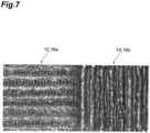
- the arrangement pitch may be approximately equal to the spot diameter of the marking laser beam as illustrated in FIG. 6(a) , may be larger than the spot diameter of the marking laser beam as illustrated in FIG. 6(b) , or may be smaller than the spot diameter of the marking laser beam as illustrated in FIG. 6(c) . That is, the laser grooves adjacent to each other in the row direction may adjoin to each other (see FIG. 6(a) ), may be spaced apart from each other (see FIG.
- the pulse marks may be arranged at a feed pitch equal to or smaller than the spot diameter in the scan direction of the marking laser beam.
- the scan direction of the marking laser beam is different from the scan direction of the base laser beam. That is, the scan direction of the marking laser beam may be opposite to or may intersect the scan direction of the base laser beam. In the example illustrated in FIG. 7 , the scan direction of the marking laser beam is orthogonal to the scan direction of the base laser beam.
- the stack 2 is formed by blanking and stacking blanked members W from an electrical steel sheet (workpiece plate) which is a strip-like metal plate.
- the base region 12 is formed on the surface 2b of the stack 2 (the outer surface of the blanked member W forming the top layer or the bottom layer of the stack 2) by using the base laser beam.
- the base region 12 is formed by repeatedly scanning with the base laser beam along a predetermined direction A over multiple rows.
- the entire region where the identification code 10 is to be formed is irradiated with the base laser beam. That is, in the present embodiment, even the cells 16 in which the black marking 14 is to be formed are irradiated with the base laser beam.
- the cells 16 to serve as the black cells 16b are specified from among a plurality of cells 16, in accordance with the identification code 10 to be formed.
- the black marking 14 is formed on the base region 12 using the marking laser beam. The black marking 14 is formed by repeatedly scanning with the marking laser beam along a predetermined direction B different from the direction A over multiple rows.
- the specified cells 16 may be irradiated with the marking laser beam such that the parameters a, b, and n satisfy Expression 3, Expression 4, or Expression 5.
- b ⁇ n / a ⁇ 1 b ⁇ n / a ⁇ 2 b ⁇ n / a ⁇ 3 When Expression 3 is satisfied, the filling ratio of each black cell 16b is equal to or greater than 100% (see FIG. 6(a) as an example of the filling ratio of about 100%).
- Expression 4 the filling ratio of each black cell 16b is equal to or greater than 200%.
- Expression 5 the filling ratio of each black cell 16b is equal to or greater than 300% (see FIG.
- the length a is determined, for example, based on the size of the identification code 10 (base region 12) and the data capacity of the identification code 10.
- the pulse diameter b is determined, for example, based on the output level of the marking laser beam and the material of the irradiation target (stack 2).
- the stacked rotor core 1 is finished when the identification code 10 is formed on the surface 2b of the stack 2 through the steps described above.
- the identification code 10 is read, for example, by using a reader 20 illustrated in FIG. 9 .
- the reader 20 includes a transportation conveyor 22, a camera 24 for reading, and a controller 26.
- the transportation conveyor 22 operates based on an instruction from the controller 26 and has the function of transporting the stacked rotor core 1 placed thereon in a predetermined direction.
- the camera 24 is positioned above the transportation conveyor 22.
- the camera 24 operates based on an instruction from the controller 26 and captures an image of the identification code 10 when the stacked rotor core 1 transported by the transportation conveyor 22 passes through below the camera 24.
- the controller 26 processes the captured image data captured by the camera 24 and reads the identification code 10. When it is determined that the identification code 10 fails to be read, the controller 26 allows the camera 24 to repeatedly capture an image of the identification code 10 as long as the stacked rotor core 1 is present within the imaging range of the camera 24.
- reading success rate refers to the rate at which the reading by the camera 24 is successful when the identification code 10 is read 50 times by the camera 24.
- FIG. 10(a) illustrates the result when one side of the cell 16 was 0.15 mm, and the number of scans of the marking laser beam was changed from 4 to 32 (for 16 or more scans, only even number of scans).
- the number of scans was four (the filling ratio was 80%), the reading success rate was 35%.
- the reading success rate was 5 (the filling ratio was 100%), the reading success rate was 37%.
- the number of scans was six (the filling ratio was 120%), the reading success rate was 39%.
- the number of scans was seven (the filling ratio was 140%), the reading success rate was 42%.
- the number of scans was eight (the filling ratio was 160%), the reading success rate was 45%.
- the number of scans was nine (the filling ratio was 180%), the reading success rate was 72%.
- the number of scans was ten or more (the filling ratio was 200% or more), the reading success rate was 100%.
- FIG. 10(b) illustrates the result when one side of the cell 16 was 0.285 mm, and the number of scans of the marking laser beam was changed from 6 to 32 (for 16 or more scans, only even number of scans).
- the number of scans was six (the filling ratio was 63%), the reading success rate was 33%.
- the number of scans was seven (the filling ratio was 73.7%), the reading success rate was 35%.
- the reading success rate was 42%.
- the number of scans was nine (the filling ratio was 94.7%), the reading success rate was 44%.
- the reading success rate was 44%.
- the reading success rate was 43%.
- the reading success rate was 56%.
- the number of scans was thirteen (the filling ratio was 136.8%)
- the reading success rate was 56%.
- the reading success rate was fourteen (the filling ratio was 147.4%)
- the reading success rate was 60%.
- the number of scans was fifteen (the filling ratio was 157.9%)
- the reading success rate was 57%.
- the number of scans was sixteen (the filling ratio was 168.4%)
- the reading success rate was 62%.
- the number of scans was eighteen (the filling ratio was 189.4%)
- the reading success rate was 80%.
- the reading success rate was 100%.
- the base region 12 is firstly formed on the surface 2b of the stack 2 and thereafter the black marking 14 is formed in the base region 12.
- the stacked rotor core 1 is thus obtained in which the identification code 10 comprising a combination of the black marking 14 and the base region 12 is formed on the surface 2b of the stack 2.
- the black marking 14 is therefore present in the base region 12 on the even surface 2b. Accordingly, the contrast between the black marking 14 and the base region 12 is improved. As a result, the readability of the identification code 10 can be enhanced.
- the base region 12 is formed by repeatedly scanning with the base laser beam along the direction A over multiple rows
- the black marking 14 is formed by repeatedly scanning with the marking laser beam along the direction B different from the direction A over multiple rows. That is, the laser grooves that form the base region 12 extend in the same direction A in any rows. With this configuration, any incident light on the base region 12 is likely to be reflected approximately in the same direction. Similarly, the laser grooves that form the black marking 14 extend in the same direction B in any rows. With this configuration, any incident light on the black marking 14 is likely to be reflected approximately in the same direction. Accordingly, the contrast between the black marking 14 and the base region 12 is more improved. As a result, the readability of the identification code 10 can be more enhanced.
- only white cells 16a are first obtained by repeatedly scanning along the direction A while irradiating only the cells 16 in which the base region 12 is to be formed in the identification code 10 with the base laser beam over multiple rows.
- only black cells 16b are then obtained by repeatedly scanning along the direction B while irradiating only the cells 16 in which the black marking 14 is to be formed in the identification code 10 with the marking laser beam over multiple rows.
- only black cells 16b are first obtained by repeatedly scanning along the direction B while irradiating only the cells 16 in which the black marking 14 is to be formed in the identification code 10 with the marking laser beam over multiple rows.
- only white cells 16a are then obtained by repeatedly scanning along the direction A while irradiating only the cells 16 in which the base region 12 is to be formed in the identification code 10 with the base laser beam over multiple rows. With this process, the base region 12 and the black marking 14 are individually formed with almost no overlap with each other.
- the direction B which is the scan direction of the marking laser beam may not intersect the direction A which is the scan direction of the base laser beam.
- the direction B may be approximately the same direction as the direction A or may be approximately the opposite direction.
- the scan direction of the base laser beam in forming the base region 12 may not be necessarily the direction A and may be a variety of directions.
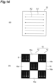
- the scan direction of the base laser beam in forming the base region 12 may be meandering, may be opposite between the forward path and the return path (see FIG. 14 ), or may be spiral (see FIG. 15 ).
- the base region 12 is formed by scanning with the base laser beam so as to reciprocate in a direction A1 and a direction A2 that is the opposite direction to the direction A1 (see FIG. 14(a) ). Thereafter, the marking laser beam is scanned along the direction B different from the directions A1 and A2 to form the black marking 14 (see FIG.
- the base region 12 is formed by repeatedly scanning with the base laser beam along a direction Al, scanning with the base laser beam from the end point along a direction A2 orthogonal to the direction Al, scanning with the base laser beam from the end point along a direction A3 orthogonal to the direction A2, and scanning with the base laser beam from the end point along a direction A4 orthogonal to the direction A3 (see FIG. 15(a) ). Thereafter, the marking laser beam is scanned along the direction B different from the directions A1 and A3 to form the black marking 14 (see FIG. 15(b) ).
- the scan direction of the marking laser beam in forming the black marking 14 may not be necessarily the direction B and may be a variety of directions.
- the scan direction of the marking laser beam in forming the black marking 14 may be meandering, may be opposite between the forward path and the return path, or may be spiral.
- the arrangement pitch of laser grooves in the black cell 16b may be constant or may be irregular. That is, the interval between adjacent laser grooves may be a regular interval or may not be a regular interval. When the interval between adjacent laser grooves is not a regular interval, the laser grooves are allocated uniformly to some extent in the cell 16.
- the black marking 14 may be directly formed on the surface 2b of the stack 2 without forming the base region 12.
- the filling ratio may be less than 50% in the black cells 16b.
- a metal end plate made of stainless steel may be disposed on each of both end surfaces of the stack 2 in order to suppress demagnetization of the magnet, and the identification code 10 may be provided on the end plate.
- the metal end plate may undergo predetermined surface treatment, which may make the gloss of the surface of the end plate uneven or make the surface of the metal end plate into the mirror surface state.
- the present invention can enhance the contrast between the black marking 14 and the surrounding thereof and thereby enhance the readability of the identification code 10.
- imaging conditions such as illumination may be changed as appropriate so as to capture a clear image of the identification code 10.
- the identification code 10 may comprise anything other than a combination of the white cells 16a and the black cells 16b. That is, the identification code 10 may comprise a combination of other colors, in addition to or instead of white and black as long as the contrast is enhanced.
- the identification code 10 may be a multilayered two-dimensional code (two-dimensional code formed by multilayering color information).
- An example of the multilayered two-dimensional code is PM code (registered trademark).
- the base region 12 may be formed as follows. First of all, a predetermined region of the surface 2b of the stack 2 (the outer surface of the blanked member W forming the top layer or the bottom layer of the stack 2) is subjected to pretreatment (rough treatment) by using the base laser beam. Specifically, scanning along a predetermined direction A (see FIG. 8(a) ) while irradiating the surface 2b with the base laser beam at a first output level is repeated over multiple rows. A preliminary region (not illustrated) is thus formed on the surface 2b. In the preliminary region, rolling marks on the surface Wa are roughly smoothed.
- the protrusions and depressions with a height of approximately a few ⁇ m to a few tens of ⁇ m due to rolling marks become protrusions and depressions with a height of approximately 5 ⁇ m or less (see the solid line in FIG. 16(a) ).
- the preliminary region is subjected to main treatment (finishing) by using the base laser beam. Specifically, scanning along a predetermined direction A (see FIG. 8(a) ) while irradiating the preliminary region with the base laser beam at a second output level lower than the first output level is repeated over multiple rows.
- the second output level may be, for example, equal to or lower than half of the first output level, may be equal to or lower than one-third of the first output level, or may be equal to or lower than one-fourth of the first output level.
- the base region 12 is thus formed on the surface 2b. In the base region 12, the surface of the preliminary region is even more flattened.
- the protrusions and depressions with a height of about 5 ⁇ m or less in the preliminary region become protrusions and depressions with a height of about 1 ⁇ m or less (see the solid line in FIG. 16(b) ).
- the black marking 14 is formed in the thus formed base region 12, whereby the contrast between the black marking 14 and the base region 12 is even more improved. As a result, the readability of the identification code 10 can be significantly enhanced.
- the present invention may be applied not only to the stacked rotor core 1 but also to a stacked stator core, or the present invention may be applied to any other various metal products.
- a method of manufacturing a metal product according to an example of the present disclosure includes forming a base region on a surface of a metal member by repeatedly scanning along a predetermined first direction while irradiating the surface of the metal member with a base laser beam over multiple rows, and forming a marking by repeatedly scanning along a predetermined second direction while irradiating the surface of the metal member with a marking laser beam over multiple rows.
- the second direction is different from the first direction.
- An identification code having a predetermined pattern comprises a combination of the base region and the marking.
- Example 1 comprises forming the base region on the surface of the metal member and forming the marking on the surface of the metal member.
- the metal product is obtained in which the identification code comprising the combination of the marking and the base region is formed on the surface of the metal member.
- the marking is present in a region surrounded by the base region with an even surface. Accordingly, the contrast between the marking and the base region is improved. As a result, the readability of the identification code can be enhanced.
- Example 1 comprises forming the marking by repeatedly scanning with the base laser beam along the first direction over multiple rows, and forming the marking by repeatedly scanning with the marking laser beam along the second direction over multiple rows. That is, the laser grooves that form the base region extend in the same first direction in any rows. With this configuration, any incident light on the base region is likely to be reflected approximately in the same direction. Similarly, the laser grooves that form the marking extend in the same second direction in any rows. With this configuration, any incident light on the marking is likely to be reflected approximately in the same direction. Accordingly, the contrast between the marking and the base region is more improved. As a result, the readability of the identification code can be more enhanced.
- the second direction which is the scan direction of the marking laser beam is a direction different from the first direction which is the scan direction of the base laser beam.
- forming the marking may include forming the marking by irradiating the base region with the marking laser beam.
- Example 3 In the method in Example 1, the base region and the marking may be formed in regions that do not overlap each other.
- Example 4 In the method described in any one of Examples 1 to Example 3, the second direction may intersect the first direction. In this case, the contrast between the marking and the base region is even more improved. As a result, the readability of the identification code can be even more enhanced.
- the base laser beam and the marking laser beam may comprise pulsed laser light
- the base laser beam may be scanned at a feed pitch equal to or smaller than a spot diameter in the first direction and at an arrangement pitch equal to or smaller than a spot diameter in a row direction
- the marking laser beam may be scanned at a feed pitch equal to or smaller than a spot diameter in the second direction and at a predetermined arrangement pitch in a row direction.
- the marking may comprise a combination of cells each having a square shape, and forming the marking may include irradiating each of the cells with the marking laser beam such that Expression 6 is satisfied: b ⁇ n / a ⁇ 0.5 where the parameters a, b, and n are defined as:
- Example 7 In the method in Example 6, forming the marking may include irradiating each of the cells with the marking laser beam such that Expression 7 is satisfied. b ⁇ n / a ⁇ 1 In this case, the filling ratio is equal to or higher than 100%. Thus, since the filling ratio of each cell is sufficiently large, the contrast between the marking and the base region is significantly improved. As a result, the readability of the identification code can be significantly enhanced.
- Example 8 In the method in any one of Example 1 to Example 7, the marking may comprise a black marking formed by oxidizing the surface of the metal member by the marking laser beam.
- Example 9 In the method in any one of Example 1 to Example 8, forming the base region may include repeatedly scanning along the first direction while irradiating the surface of the metal member with the base laser beam at a first output level over multiple rows, and repeatedly scanning along the first direction while irradiating a region with the base laser beam at a second output level lower than the first output level over multiple rows, the region being irradiated with the base laser beam at the first output level.
- laser with a high output level is firstly emitted. With this process, rolling marks on the surface of the metal member are roughly smoothed (rough treatment). Thereafter, the region irradiated with laser with a high output level is irradiated with laser with a low output level.
- the protrusions and depressions of the roughly smoothed surface of the metal member are even more flattened (finishing).
- the marking is formed in the thus formed base region, whereby the contrast between the marking and the base region is even more improved. As a result, the readability of the identification code can be significantly enhanced.
- a method of manufacturing a metal product includes forming a marking by repeatedly scanning along a predetermined first direction while irradiating a surface of a metal member with a marking laser beam over multiple rows, the marking laser beam generated by a pulse-like laser light source.
- the marking laser beam is scanned at a feed pitch equal to or smaller than a spot diameter in the first direction and at a predetermined arrangement pitch in a row direction.
- the marking comprises a combination of cells each having a square shape. Forming the marking includes irradiating each of the cells with the marking laser beam such that Expression 8 is satisfied: b ⁇ n / a ⁇ 0.5 where parameters a, b, and n are defined as:
- each cell is irradiated with the marking laser beam such that Expression 8 is satisfied.
- the filling ratio is equal to or greater than 50%. Accordingly, since the filling ratio of each cell is relatively large, the contrast between the marking and the surrounding region is even more improved. As a result, the readability of the identification code can be even more enhanced.
- Example 11 In the method in Example 10, forming the marking may include irradiating each of the cells with the marking laser beam such that Expression 9 is satisfied. b ⁇ n / a ⁇ 1 In this case, the similar effects as in Example 5 can be achieved.
- Example 12 The method in Example 10 or Example 11 may further include, before forming the marking, forming a base region on the surface of the metal member by repeatedly scanning along a predetermined second direction while irradiating the surface of the metal member with a base laser beam over multiple rows.
- An identification code having a predetermined pattern may comprise a combination of the base region and the marking.
- Forming the marking may include irradiating the base region with the marking laser beam. In this case, the similar effects as in Example 1 can be achieved.
- Example 13 The method in Example 10 or Example 11 may further include forming a base region on the surface of the metal member by repeatedly scanning along a predetermined second direction while irradiating the surface of the metal member with a base laser beam over multiple rows.
- An identification code having a predetermined pattern may comprise a combination of the base region and the marking.
- the base region and the marking may be formed in regions that do not overlap each other. In this case, the similar effects as in Example 1 can be achieved.
- Example 14 In the method described in Example 12 or Example 13, the first direction may intersect the second direction. In this case, the similar effects as in Example 4 can be achieved.
- the base laser beam may comprise pulse-like laser light and is scanned at a feed pitch equal to or smaller than a spot diameter in the second direction and at an arrangement pitch equal to or smaller than a spot diameter in a row direction.
- Example 16 in the method in any one of Example 12 to Example 15, forming the base region may include repeatedly scanning along the first direction while irradiating the surface of the metal member with the base laser beam at a first output level over multiple rows, and repeatedly scanning along the first direction while irradiating a region with the base laser beam at a second output level lower than the first output level over multiple rows, the region being irradiated with the base laser beam at the first output level.
- forming the base region may include repeatedly scanning along the first direction while irradiating the surface of the metal member with the base laser beam at a first output level over multiple rows, and repeatedly scanning along the first direction while irradiating a region with the base laser beam at a second output level lower than the first output level over multiple rows, the region being irradiated with the base laser beam at the first output level.
- the similar effects as in Example 9 can be achieved.
- the marking may comprise a black marking formed by oxidizing the surface of the metal member by the marking laser beam.
- a metal product according to another example of the present disclosure comprises an identification code having a predetermined pattern comprising a combination of a base region and a marking, the identification code being formed on a surface of a metal member.
- the base region is configured such that laser grooves extending in a predetermined first direction are arranged in multiple rows.
- the marking is configured such that laser grooves extending in a predetermined second direction different from the first direction are arranged in multiple rows.
- Example 18 achieves the similar effects as Example 1.
- Example 19 In the metal product in Example 18, the second direction may intersect the first direction. In this case, the similar effects as in Example 2 can be achieved.
- the base region may comprise pulse marks that are arranged at a feed pitch equal to or smaller than a spot diameter in the first direction and pulse marks that are arranged at an arrangement pitch equal to or smaller than a spot diameter in a row direction.
- the marking may comprise pulse marks that are arranged at a feed pitch equal to or smaller than a spot diameter in the second direction and pulse marks that are arranged at a predetermined arrangement pitch in a row direction.
- Example 21 In the metal product in any one of Example 18 to Example 20, the marking may comprise a black marking formed by oxidizing the surface of the metal member.
Landscapes
- Engineering & Computer Science (AREA)
- Physics & Mathematics (AREA)
- Optics & Photonics (AREA)
- Theoretical Computer Science (AREA)
- General Physics & Mathematics (AREA)
- Mechanical Engineering (AREA)
- Plasma & Fusion (AREA)
- Power Engineering (AREA)
- Manufacturing & Machinery (AREA)
- Health & Medical Sciences (AREA)
- Electromagnetism (AREA)
- General Health & Medical Sciences (AREA)
- Toxicology (AREA)
- Artificial Intelligence (AREA)
- Computer Vision & Pattern Recognition (AREA)
- Ceramic Engineering (AREA)
- Laser Beam Processing (AREA)
Description
- The present disclosure relates to a method of manufacturing a metal product and a metal product.
-
Patent Literature 1 discloses a method of producing a metal product by forming a two-dimensional code on a surface of a metal member. The method includes forming a black marking having a predetermined pattern by repeating the process of irradiating a surface of a metal member with a laser beam to oxidize metal and printing circular dots on the surface, the dots corresponding to the beam shape. A two-dimensional code formed with a combination of a black cell that is a group of circular dots and a white cell that is a region not irradiated with the laser beam is thus formed on the surface of the metal member. The two-dimensional code has the function as an identification code that identifies each individual metal product (for example, product type, production date, materials used, and production line).Patent Literature 2 relates to a metal case used for electronic parts, comprising a base area with first recesses and second recesses formed by laser irradiation, wherein the second recesses have a different light reflection density from the first recesses and represent characters or figures in the base area.Patent Literature 3 describes a process of cleaning a marking area by irradiating a laser beam by scanning the marking area on the surface of an object with an energy lower than the energy of the laser beam for marking the area.Patent Literature 4 describes a method for laser marking on a metallic member.Patent Literature 5 describes a method of marking an article. -
- Patent Literature 1:
Japanese Unexamined Patent Publication No. 2000-222516 - Patent Literature 2:
JP 2008 012567 A - Patent Literature 3:
JP H10 34359 A - Patent Literature 4:
EP 2 692 474 A1 - Patent Literature 5:
US 2014/015170 A1 - The metal member on which a two-dimensional code is to be formed is typically obtained by rolling a metal material through rolls. In this case, scratches on the surfaces of the rolls may be transferred onto the surface of the metal member to leave fine linear marks (also called rolling marks) on the surface of the metal member. Alternatively, the metal member may undergo a variety of surface treatment before an identification code is formed on the metal member. With this surface treatment, the gloss of the surface of the metal member may become uneven or the surface of the metal member may become a mirror surface.
- In such a case, when the metal member is irradiated with flashlight in order to read the two-dimensional code formed on the metal surface by using a scanning camera, light may irregularly enter on the scanning camera due to rolling marks, gloss, and the like, or light specularly reflected on the metal surface may enter on the scanning camera. This reduces the readability of a two-dimensional code and in addition causes concern that the readability of a two-dimensional code varies for each metal product.
- The present disclosure provides a method of manufacturing a metal product and a metal product with enhanced readability of an identification code.
- The present invention is defined in the claims. In the following description, although numerous features may be designated as optional, it is nevertheless acknowledged that all features comprised in the independent claims are not to be read as optional.
- In the method of manufacturing a metal product and the metal product according to the present disclosure, the readability of the identification code can be enhanced.
-
-
FIG. 1 is a perspective view illustrating an example stacked rotor core. -
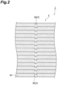
FIG. 2 is a cross-sectional view along line II-II inFIG. 1 . -
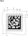
FIG. 3 is a top view illustrating an example identification code provided on the stacked rotor core. -
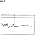
FIG. 4 is a diagram illustrating an example surface profile of a stack (blanked member). -
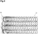
FIG. 5 is a photograph of a partially enlarged view of a base region. -
FIG. 6 is a diagram illustrating an example black cell. -
FIG. 7 is a photograph of a partially enlarged view of the vicinity of the boundary between a black marking and a base region. -
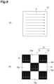
FIG. 8 is a schematic diagram for explaining an example process of forming an identification code. -
FIG. 9 is a diagram for explaining a method of reading the identification code. -
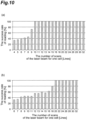
FIG. 10(a) is a graph illustrating the relation between the number of scans of a marking laser beam for one cell of a 0.15 mm square and the success rate of reading the identification code formed with the corresponding number of scans. -
FIG. 10(b) is a graph illustrating the relation between the number of scans of a marking laser beam for one cell of a 0.285 mm square and the success rate of reading the identification code formed with the corresponding number of scans. -
FIG. 11 is a diagram illustrating an example captured image of the identification code by a camera. -
FIG. 12 is a schematic diagram for explaining another example process of forming an identification code. -
FIG. 13 is a schematic diagram for explaining another example process of forming an identification code. -
FIG. 14 is a schematic diagram for explaining another example process of forming an identification code. -
FIG. 15 is a schematic diagram for explaining another example process of forming an identification code. -
FIG. 16 is a schematic diagram for explaining another example process of forming a base region. - An exemplary embodiment according to the present disclosure will be described in detail below with reference to the drawings. In the following description, the same elements or the elements having the same functions are denoted by the same reference signs and an overlapping description will be omitted.
- First of all, referring to
FIG. 1 andFIG. 2 , a structure of astacked rotor core 1, which is an example of the metal product, is described. The stackedrotor core 1 is a part of a rotor. The rotor is formed by attaching end plates and a shaft (which are not illustrated) to the stackedrotor core 1. As illustrated inFIG. 1 , thestacked rotor core 1 includes a stack 2 (metal member), connectingtab portions 3, and anidentification code 10. - The
stack 2 has a cylindrical shape. More specifically, as illustrated inFIG. 1 , a throughhole 2a (center hole) extending along the center axis Ax is provided at the center portion of thestack 2. A shaft may be disposed in the throughhole 2a. - The
stack 2 is astack 2 in which a plurality of blanked members W are stacked. The blanked member W is a plate formed by blanking an electrical steel sheet (metal plate) into a predetermined shape. Since the electrical steel sheet is obtained by rolling by using rolls, the surface of the blanked member W may have rolling marks. Thestack 2 may be formed by stacking a plurality of blanked members W while shifting the angles of the blanked members W from each other, which is called rotational stacking. The angle of rotational stacking may be set to a desired value. - In the present embodiment, the blanked members W adjacent in the stacking direction are fastened to each other by the connecting
tab portions 3. Specifically, as illustrated inFIG. 2 , the connectingtab portions 3 include a connectingtab 3a formed at a blanked member W forming a layer other than the bottom layer of thestack 2 and a throughhole 3b formed at a blanked member W forming the bottom layer of thestack 2. The connectingtab 3a has a depression formed on the front surface side of a blanked member W and a projection formed on the back surface side of the blanked member W. The depression of the connectingtab 3a of one blanked member W is joined to the projection of the connectingtab 3a of another blanked member W adjacent to the front surface side of the one blanked member W. The projection of the connectingtab 3a of one blanked member W is joined to the depression of the connectingtab 3a of still another blanked member W adjacent to the back surface side of the one blanked member W. The projection of the connectingtab 3a of the blanked member W adjacent to the bottom layer of thestack 2 is joined to the throughhole 3b. The throughhole 3b has the function of preventing the blanked member W subsequently formed from being fastened to the previously producedstack 2 by the connectingtab 3a whenstacks 2 are continuously produced. - A plurality of blanked members W may be fastened to each other by a variety of known methods, instead of the connecting
tab portions 3. A plurality of blanked members W may be joined to each other, for example, by adhesive or a resin material or joined to each other by welding. Alternatively, the blanked member W may be provided with a temporarily-connecting tab, and thestack 2 may be obtained by fastening a plurality of blanked members W to each other through temporarily-connecting tabs to form a stack, and thereafter removing the temporarily-connecting tabs from the stack.
The "temporarily-connecting tab" means a connecting tab used for temporarily integrating a plurality of blanked members W and removed in the process of producing a product (stack 2). - At least one magnet insertion hole (not illustrated) extending along the extending direction (stacking direction) of the center axis Ax and passing through the
stack 2 may be provided in thestack 2. The magnet insertion hole may be filled with a resin material with a permanent magnet (not illustrated) disposed therein. The resin material has the function of fixing a permanent magnet in the magnet insertion hole and the function of joining the blanked members W adjacent in the vertical direction together. - As illustrated in
FIG. 1 , oneidentification code 10 is provided on asurface 2b (upper surface or lower surface) of thestack 2, that is, the outer surface of the blanked member W forming the top layer or the bottom layer of thestack 2. Theidentification code 10 has the function of holding individual information (for example, product type, production date, materials used, and production line) for identifying each individual stackedrotor core 1 having theidentification code 10. Theidentification code 10 may be anything that can hold the individual information with a combination of light pattern and dark pattern. Theidentification code 10 may be a barcode or a two-dimensional code, for example. Examples of the two-dimensional code include QR code (registered trademark), DataMatrix, and Vericode. As illustrated in detail inFIG. 3 , theidentification code 10 includes abase region 12 and ablack marking 14. Theidentification code 10 has a predetermined pattern with a combination of thebase region 12 and theblack marking 14. - As illustrated in
FIG. 3 , theidentification code 10 has a plurality ofvirtual cells 16. A plurality ofcells 16 are arranged in a grid pattern and correspond to the size of theidentification code 10 as a whole. Although lines in a grid pattern that define thecells 16 are illustrated inFIG. 3 , these lines are drawn for the sake of convenience to facilitate understanding of the invention and do not exist in theactual identification code 10. The size of thecell 16 is not limited and may be a variety of sizes depending on the required performance of theidentification code 10. The shape of thecell 16 is not limited and may be, for example, square, rectangular, circular, polygonal, and any other undefined shapes. In the present embodiment, thecell 16 is set to, for example, a 0.15 mm by 0.15 mm square shape or a 0.285 mm by 0.285 mm square shape. In the present description, acell 16 in which thebase region 12 is formed is calledwhite cell 16a, and acell 16 in which the black marking 14 is formed is calledblack cell 16b. - The
base region 12 is formed by irradiating thesurface 2b of thestack 2 with a base laser beam. The size of thebase region 12 is not limited and may be a variety of sizes depending on the size of thestack 2, the kind of material of the blanked member W, the position of theidentification code 10 formed, and the like. The shape of thebase region 12 is not limited and may be, for example, square, rectangular, circular, polygonal, and any other undefined shapes. In the present embodiment, thebase region 12 is set to, for example, a 5 mm by 5 mm square shape. - Examples of the base laser beam for forming the
base region 12 include YAG laser, YVO4 laser, and fiber laser. The base laser beam may be continuous wave (CW) laser or may be pulsed laser. The beam diameter (the diameter of light ray before the beam reaches a radiation target), the spot diameter (the diameter of light ray on the surface of a radiation target when the base laser beam radiates the radiation target), and the output level of the base laser beam are not limited and may be in various sizes depending on the kind of beam, the kind of material of the blanked member W, the thickness of the blanked member W, and the like. Even with the same beam diameter, the spot diameter may vary because the melting state by the beam varies depending on the kind of material of the radiation target irradiated with the base laser beam. - Since the
surface 2b of the stack 2 (blanked member W) is treated by the base laser beam, as illustrated inFIG. 4 , thebase region 12 has an extremely high flatness. For example, as illustrated inFIG. 4 , the surface of the blanked member W with rolling marks have protrusions and depressions with a height of approximately a few µm to a few tens of µm, whereas the height of protrusions and depressions present on the surface of thebase region 12 is approximately 1 µm or less. - The
base region 12 is formed by repeatedly scanning along a predetermined direction A (seeFIG. 8(a) ) while irradiating the surface of the stack 2 (blanked member W) with the base laser beam over multiple rows. That is, as illustrated inFIG. 5 , thebase region 12 is configured such that laser grooves extending along the direction A (scan direction) are arranged in multiple rows.FIG. 5 illustrates a state of laser grooves when pulsed laser is used as the base laser beam, as an example. One laser groove inFIG. 5 is formed with a plurality of pulse marks (the marks produced when the surface of the blanked member W is irradiated with the pulsed base laser beam) continuous from the left side to the right side inFIG. 5 . That is, the laser groove inFIG. 5 is formed by scanning from the left side to the right side inFIG. 5 by the base laser beam. - In the row direction that is the direction in which the scan rows of the base laser beam are arranged (the direction in which the laser grooves are arranged), the arrangement pitch of the base laser beam (the arrangement pitch of laser grooves) may be equal to or smaller than the spot diameter of the base laser beam. That is, the laser grooves adjacent in the row direction at least partially overlap each other. When the base laser beam is pulsed laser, the pulse marks may be arranged at a feed pitch equal to or smaller than the spot diameter in the scan direction of the base laser beam.
- In the present embodiment, the
black marking 14 is formed by irradiating thebase region 12 with a marking laser beam. Theblack marking 14 is the blanked member W oxidized by the marking laser beam and becoming black. Theblack marking 14 has a predetermined pattern and forms theidentification code 10 together with the surroundingbase region 12. Specifically, as illustrated inFIG. 3 , theblack marking 14 is a group ofblack cells 16b formed by irradiating thecells 16 with the marking laser beam and filling thecells 16 with black color. - Examples of the marking laser beam for forming the
black marking 14 include YAG laser, YVO4 laser, and fiber laser. The marking laser beam may be continuous wave laser or may be pulsed laser. The beam diameter (the diameter of light ray before the beam reaches a radiation target), the spot diameter (the diameter of light ray on the surface of a radiation target when the marking laser beam radiates the radiation target), and the output level of the marking laser beam are not limited and may be in various sizes depending on the kind of beam, the kind of material of the blanked member W, the thickness of the blanked member W, and the like. However, the output level of the marking laser beam may be greater than the output level of the base laser beam, for example, may be 10 times or more as large as the output level of the base laser beam. Even with the same beam diameter, the spot diameter may vary because the melting state by the beam varies depending on the kind of material of the radiation target irradiated with the marking laser beam. - The
black cell 16b is formed by repeatedly scanning along a predetermined direction B (seeFIG. 8(b) ) while irradiating thebase region 12 with the marking laser beam over multiple rows. That is, as illustrated inFIG. 6 andFIG. 7 , thebase region 12 is configured such that laser grooves extending along the direction B (scan direction) are arranged in multiple rows.FIG. 6 andFIG. 7 both illustrate a state of laser grooves when pulsed laser is used as the marking laser beam, as an example. One laser groove inFIG. 6 andFIG. 7 is formed with a plurality of pulse marks (the marks produced when the surface of thebase region 12 is irradiated with the pulsed marking laser beam) continuous from the upper side to the lower side inFIG. 6 andFIG. 7 . That is, the laser groove inFIG. 6 andFIG. 7 is formed by scanning from the upper side to the lower side inFIG. 6 andFIG. 7 by the marking laser beam. - In the row direction that is the direction in which the scan rows of the marking laser beam are arranged (the direction in which the laser grooves are arranged), the arrangement pitch of the marking laser beam (the arrangement pitch of laser grooves) may be set to a predetermined interval. For example, the arrangement pitch may be approximately equal to the spot diameter of the marking laser beam as illustrated in
FIG. 6(a) , may be larger than the spot diameter of the marking laser beam as illustrated inFIG. 6(b) , or may be smaller than the spot diameter of the marking laser beam as illustrated inFIG. 6(c) . That is, the laser grooves adjacent to each other in the row direction may adjoin to each other (seeFIG. 6(a) ), may be spaced apart from each other (seeFIG. 6(b) ), or may at least partially overlap each other (seeFIG. 6(c) ). When the marking laser beam is pulsed laser, the pulse marks may be arranged at a feed pitch equal to or smaller than the spot diameter in the scan direction of the marking laser beam. - The scan direction of the marking laser beam is different from the scan direction of the base laser beam. That is, the scan direction of the marking laser beam may be opposite to or may intersect the scan direction of the base laser beam. In the example illustrated in
FIG. 7 , the scan direction of the marking laser beam is orthogonal to the scan direction of the base laser beam. - A method of forming the
identification code 10 on thestack 2, that is, a method of manufacturing the stackedrotor core 1 will now be described. First of all, thestack 2 is formed by blanking and stacking blanked members W from an electrical steel sheet (workpiece plate) which is a strip-like metal plate. - Next, as illustrated in
FIG. 8(a) , thebase region 12 is formed on thesurface 2b of the stack 2 (the outer surface of the blanked member W forming the top layer or the bottom layer of the stack 2) by using the base laser beam. In this case, thebase region 12 is formed by repeatedly scanning with the base laser beam along a predetermined direction A over multiple rows. In the present embodiment, the entire region where theidentification code 10 is to be formed is irradiated with the base laser beam. That is, in the present embodiment, even thecells 16 in which the black marking 14 is to be formed are irradiated with the base laser beam. - Next, as illustrated in
FIG. 8(b) , thecells 16 to serve as theblack cells 16b are specified from among a plurality ofcells 16, in accordance with theidentification code 10 to be formed. Next, theblack marking 14 is formed on thebase region 12 using the marking laser beam. Theblack marking 14 is formed by repeatedly scanning with the marking laser beam along a predetermined direction B different from the direction A over multiple rows. - In forming the
black marking 14, when parameters a, b, and n are defined as: - a : the length of one side of each
cell 16; - b: the pulse diameter of the marking laser beam; and
- n: a number of scans of the marking laser beam per
cell 16 - In forming the
black marking 14, the specifiedcells 16 may be irradiated with the marking laser beam such that the parameters a, b, and n satisfyExpression 3,Expression 4, orExpression 5.


Expression 3 is satisfied, the filling ratio of eachblack cell 16b is equal to or greater than 100% (seeFIG. 6(a) as an example of the filling ratio of about 100%). WhenExpression 4 is satisfied, the filling ratio of eachblack cell 16b is equal to or greater than 200%. WhenExpression 5 is satisfied, the filling ratio of eachblack cell 16b is equal to or greater than 300% (seeFIG. 6(c) as an example of the filling ratio of about 300%). In these cases, since the filling ratio of eachblack cell 16b is sufficiently large, the contrast between theblack marking 14 and thebase region 12 is significantly improved. Accordingly, the readability of theidentification code 10 can be significantly enhanced. - The length a is determined, for example, based on the size of the identification code 10 (base region 12) and the data capacity of the
identification code 10. The pulse diameter b is determined, for example, based on the output level of the marking laser beam and the material of the irradiation target (stack 2). - The stacked
rotor core 1 is finished when theidentification code 10 is formed on thesurface 2b of thestack 2 through the steps described above. - A method of reading the
identification code 10 will now be described. Theidentification code 10 is read, for example, by using areader 20 illustrated inFIG. 9 . Thereader 20 includes atransportation conveyor 22, acamera 24 for reading, and acontroller 26. - The
transportation conveyor 22 operates based on an instruction from thecontroller 26 and has the function of transporting the stackedrotor core 1 placed thereon in a predetermined direction. Thecamera 24 is positioned above thetransportation conveyor 22. Thecamera 24 operates based on an instruction from thecontroller 26 and captures an image of theidentification code 10 when the stackedrotor core 1 transported by thetransportation conveyor 22 passes through below thecamera 24. Thecontroller 26 processes the captured image data captured by thecamera 24 and reads theidentification code 10. When it is determined that theidentification code 10 fails to be read, thecontroller 26 allows thecamera 24 to repeatedly capture an image of theidentification code 10 as long as thestacked rotor core 1 is present within the imaging range of thecamera 24. - Here, a test was conducted in which
square cells 16 were irradiated with the marking laser beam, which was a pulsed laser with a spot diameter of 30 µm, to form the black marking 14 in thebase region 12, theresultant identification code 10 was read by thecamera 24 from a predetermined direction (not from immediately above), and the reading success rate was determined with different sizes of thecell 16 and different numbers of scans. In the present description, "reading success rate" refers to the rate at which the reading by thecamera 24 is successful when theidentification code 10 is read 50 times by thecamera 24. -
FIG. 10(a) illustrates the result when one side of thecell 16 was 0.15 mm, and the number of scans of the marking laser beam was changed from 4 to 32 (for 16 or more scans, only even number of scans). When the number of scans was four (the filling ratio was 80%), the reading success rate was 35%. When the number of scans was five (the filling ratio was 100%), the reading success rate was 37%. When the number of scans was six (the filling ratio was 120%), the reading success rate was 39%. When the number of scans was seven (the filling ratio was 140%), the reading success rate was 42%. When the number of scans was eight (the filling ratio was 160%), the reading success rate was 45%. When the number of scans was nine (the filling ratio was 180%), the reading success rate was 72%. When the number of scans was ten or more (the filling ratio was 200% or more), the reading success rate was 100%. -
FIG. 10(b) illustrates the result when one side of thecell 16 was 0.285 mm, and the number of scans of the marking laser beam was changed from 6 to 32 (for 16 or more scans, only even number of scans). When the number of scans was six (the filling ratio was 63%), the reading success rate was 33%. When the number of scans was seven (the filling ratio was 73.7%), the reading success rate was 35%. When the number of scans was eight (the filling ratio was 84.2%), the reading success rate was 42%. When the number of scans was nine (the filling ratio was 94.7%), the reading success rate was 44%. When the number of scans was 10 (the filling ratio was 105.3%), the reading success rate was 44%. When the number of scans was eleven (the filling ratio was 115.8%), the reading success rate was 43%. When the number of scans was twelve (the filling ratio was 126.3%), the reading success rate was 56%. When the number of scans was thirteen (the filling ratio was 136.8%), the reading success rate was 56%. When the number of scans was fourteen (the filling ratio was 147.4%), the reading success rate was 60%. When the number of scans was fifteen (the filling ratio was 157.9%), the reading success rate was 57%. When the number of scans was sixteen (the filling ratio was 168.4%), the reading success rate was 62%. When the number of scans was eighteen (the filling ratio was 189.4%), the reading success rate was 80%. When the number of scans was twelve or more (the filling ratio was 210.5% or more), the reading success rate was 100%. - The test results above confirmed that when the filling ratio was 50% or more, the reading of the
identification code 10 is successful at least 30%. - In the present embodiment as described above, the
base region 12 is firstly formed on thesurface 2b of thestack 2 and thereafter theblack marking 14 is formed in thebase region 12. The stackedrotor core 1 is thus obtained in which theidentification code 10 comprising a combination of theblack marking 14 and thebase region 12 is formed on thesurface 2b of thestack 2. Theblack marking 14 is therefore present in thebase region 12 on theeven surface 2b. Accordingly, the contrast between theblack marking 14 and thebase region 12 is improved. As a result, the readability of theidentification code 10 can be enhanced. - In the present embodiment, the
base region 12 is formed by repeatedly scanning with the base laser beam along the direction A over multiple rows, and theblack marking 14 is formed by repeatedly scanning with the marking laser beam along the direction B different from the direction A over multiple rows. That is, the laser grooves that form thebase region 12 extend in the same direction A in any rows. With this configuration, any incident light on thebase region 12 is likely to be reflected approximately in the same direction. Similarly, the laser grooves that form theblack marking 14 extend in the same direction B in any rows. With this configuration, any incident light on theblack marking 14 is likely to be reflected approximately in the same direction. Accordingly, the contrast between theblack marking 14 and thebase region 12 is more improved. As a result, the readability of theidentification code 10 can be more enhanced. - In the present embodiment, the direction B which is the scan direction of the marking laser beam intersects (is orthogonal to) the direction A which is the scan direction of the base laser beam. In this configuration, the direction of reflected light from the
base region 12 and the direction of reflected light from theblack marking 14 are different directions. Accordingly, the contrast between theblack marking 14 and thebase region 12 is further improved. As a result, the readability of theidentification code 10 can be further enhanced. When the direction B which is the scan direction of the marking laser beam is the same as the direction A which is the scan direction of the base laser beam, as illustrated inFIG. 11 , the contrast is reduced and the captured image of theidentification code 10 may be unclear. - According to the present invention, the contrast between the
black marking 14 and the surrounding is enhanced, so that an image of theidentification code 10 can be captured by thecamera 24 not only from the position facing theidentification code 10 but also from the diagonal direction. Specifically, since the stackedrotor core 1 has its form changed, for example, due to insertion of a shaft into the throughhole 2a in the subsequent step, the imaging direction of theidentification code 10 by thecamera 24 tends to be limited. However, the present invention enables reading of theidentification code 10 from various directions. - Although an embodiment according to the present disclosure has been described in detail above, the foregoing embodiment is susceptible to various modifications without departing from the present invention as defined in the claims.
- (1) The
identification code 10 may comprise a combination of thebase region 12 and theblack marking 14. That is, as in the foregoing embodiment, theblack marking 14 may be formed on thebase region 12. Alternatively, thebase region 12 and theblack marking 14 may be formed so as not to overlap each other. However, overlapping of thebase region 12 and theblack marking 14 to some extent due to radiation tolerance of base laser beam and marking laser beam is acceptable. - Specifically, as illustrated in
FIG. 12(a) , onlywhite cells 16a are first obtained by repeatedly scanning along the direction A while irradiating only thecells 16 in which thebase region 12 is to be formed in theidentification code 10 with the base laser beam over multiple rows. As illustrated inFIG. 12(b) , onlyblack cells 16b are then obtained by repeatedly scanning along the direction B while irradiating only thecells 16 in which the black marking 14 is to be formed in theidentification code 10 with the marking laser beam over multiple rows. With this process, thebase region 12 and theblack marking 14 are individually formed with almost no overlap with each other. - Alternatively, as illustrated in
FIG. 13(a) , onlyblack cells 16b are first obtained by repeatedly scanning along the direction B while irradiating only thecells 16 in which the black marking 14 is to be formed in theidentification code 10 with the marking laser beam over multiple rows. As illustrated inFIG. 13(b) , onlywhite cells 16a are then obtained by repeatedly scanning along the direction A while irradiating only thecells 16 in which thebase region 12 is to be formed in theidentification code 10 with the base laser beam over multiple rows. With this process, thebase region 12 and theblack marking 14 are individually formed with almost no overlap with each other. - (2) The direction B which is the scan direction of the marking laser beam may not intersect the direction A which is the scan direction of the base laser beam. For example, the direction B may be approximately the same direction as the direction A or may be approximately the opposite direction.
- (3) The scan direction of the base laser beam in forming the
base region 12 may not be necessarily the direction A and may be a variety of directions. For example, the scan direction of the base laser beam in forming thebase region 12 may be meandering, may be opposite between the forward path and the return path (seeFIG. 14 ), or may be spiral (seeFIG. 15 ). When the scan direction of the base laser beam is opposite between the forward path and the return path, thebase region 12 is formed by scanning with the base laser beam so as to reciprocate in a direction A1 and a direction A2 that is the opposite direction to the direction A1 (seeFIG. 14(a) ). Thereafter, the marking laser beam is scanned along the direction B different from the directions A1 and A2 to form the black marking 14 (seeFIG. 14(b) ). When the scan direction of the base laser beam is spiral, thebase region 12 is formed by repeatedly scanning with the base laser beam along a direction Al, scanning with the base laser beam from the end point along a direction A2 orthogonal to the direction Al, scanning with the base laser beam from the end point along a direction A3 orthogonal to the direction A2, and scanning with the base laser beam from the end point along a direction A4 orthogonal to the direction A3 (seeFIG. 15(a) ). Thereafter, the marking laser beam is scanned along the direction B different from the directions A1 and A3 to form the black marking 14 (seeFIG. 15(b) ). Similarly, the scan direction of the marking laser beam in forming theblack marking 14 may not be necessarily the direction B and may be a variety of directions. For example, the scan direction of the marking laser beam in forming theblack marking 14 may be meandering, may be opposite between the forward path and the return path, or may be spiral. - (4) The arrangement pitch of laser grooves in the
black cell 16b may be constant or may be irregular. That is, the interval between adjacent laser grooves may be a regular interval or may not be a regular interval. When the interval between adjacent laser grooves is not a regular interval, the laser grooves are allocated uniformly to some extent in thecell 16. - (5) The
black marking 14 may be directly formed on thesurface 2b of thestack 2 without forming thebase region 12. - (6) As long as the reading success rate of the
identification code 10 exceeds 0%, the filling ratio may be less than 50% in theblack cells 16b. - (7) When a permanent magnet is provided in the
stack 2, for example, a metal end plate made of stainless steel may be disposed on each of both end surfaces of thestack 2 in order to suppress demagnetization of the magnet, and theidentification code 10 may be provided on the end plate. The metal end plate may undergo predetermined surface treatment, which may make the gloss of the surface of the end plate uneven or make the surface of the metal end plate into the mirror surface state. However, even in such a case, the present invention can enhance the contrast between theblack marking 14 and the surrounding thereof and thereby enhance the readability of theidentification code 10. - (8) When an image of the
identification code 10 is captured by thecamera 24, imaging conditions such as illumination may be changed as appropriate so as to capture a clear image of theidentification code 10. - (9) The
identification code 10 may comprise anything other than a combination of thewhite cells 16a and theblack cells 16b. That is, theidentification code 10 may comprise a combination of other colors, in addition to or instead of white and black as long as the contrast is enhanced. For example, theidentification code 10 may be a multilayered two-dimensional code (two-dimensional code formed by multilayering color information). An example of the multilayered two-dimensional code is PM code (registered trademark). - (10) The
base region 12 may be formed as follows. First of all, a predetermined region of thesurface 2b of the stack 2 (the outer surface of the blanked member W forming the top layer or the bottom layer of the stack 2) is subjected to pretreatment (rough treatment) by using the base laser beam. Specifically, scanning along a predetermined direction A (seeFIG. 8(a) ) while irradiating thesurface 2b with the base laser beam at a first output level is repeated over multiple rows. A preliminary region (not illustrated) is thus formed on thesurface 2b. In the preliminary region, rolling marks on the surface Wa are roughly smoothed. For example, with the pretreatment, the protrusions and depressions with a height of approximately a few µm to a few tens of µm (see the broken line inFIG. 16(a) ) due to rolling marks become protrusions and depressions with a height of approximately 5 µm or less (see the solid line inFIG. 16(a) ). - Next, the preliminary region is subjected to main treatment (finishing) by using the base laser beam. Specifically, scanning along a predetermined direction A (see
FIG. 8(a) ) while irradiating the preliminary region with the base laser beam at a second output level lower than the first output level is repeated over multiple rows. The second output level may be, for example, equal to or lower than half of the first output level, may be equal to or lower than one-third of the first output level, or may be equal to or lower than one-fourth of the first output level. Thebase region 12 is thus formed on thesurface 2b. In thebase region 12, the surface of the preliminary region is even more flattened. For example, with the main treatment, the protrusions and depressions with a height of about 5 µm or less in the preliminary region (see the broken line inFIG. 16(b) ) become protrusions and depressions with a height of about 1 µm or less (see the solid line inFIG. 16(b) ). Theblack marking 14 is formed in the thus formedbase region 12, whereby the contrast between theblack marking 14 and thebase region 12 is even more improved. As a result, the readability of theidentification code 10 can be significantly enhanced. - (11) The present invention may be applied not only to the stacked
rotor core 1 but also to a stacked stator core, or the present invention may be applied to any other various metal products. - Example 1. A method of manufacturing a metal product according to an example of the present disclosure includes forming a base region on a surface of a metal member by repeatedly scanning along a predetermined first direction while irradiating the surface of the metal member with a base laser beam over multiple rows, and forming a marking by repeatedly scanning along a predetermined second direction while irradiating the surface of the metal member with a marking laser beam over multiple rows. The second direction is different from the first direction. An identification code having a predetermined pattern comprises a combination of the base region and the marking.
- Example 1 comprises forming the base region on the surface of the metal member and forming the marking on the surface of the metal member. With this process, the metal product is obtained in which the identification code comprising the combination of the marking and the base region is formed on the surface of the metal member. Thus, the marking is present in a region surrounded by the base region with an even surface. Accordingly, the contrast between the marking and the base region is improved. As a result, the readability of the identification code can be enhanced.
- Example 1 comprises forming the marking by repeatedly scanning with the base laser beam along the first direction over multiple rows, and forming the marking by repeatedly scanning with the marking laser beam along the second direction over multiple rows. That is, the laser grooves that form the base region extend in the same first direction in any rows. With this configuration, any incident light on the base region is likely to be reflected approximately in the same direction. Similarly, the laser grooves that form the marking extend in the same second direction in any rows. With this configuration, any incident light on the marking is likely to be reflected approximately in the same direction. Accordingly, the contrast between the marking and the base region is more improved. As a result, the readability of the identification code can be more enhanced.
- According to Example 1, the second direction which is the scan direction of the marking laser beam is a direction different from the first direction which is the scan direction of the base laser beam. With this configuration, the direction of reflected light from the base region and the direction of reflected light from the marking are different directions. Accordingly, the contrast between the marking and the base region is further improved. As a result, the readability of the identification code can be further enhanced.
- Example 2. In the method in Example 1, forming the marking may include forming the marking by irradiating the base region with the marking laser beam.
- Example 3. In the method in Example 1, the base region and the marking may be formed in regions that do not overlap each other.
- Example 4. In the method described in any one of Examples 1 to Example 3, the second direction may intersect the first direction. In this case, the contrast between the marking and the base region is even more improved. As a result, the readability of the identification code can be even more enhanced.
- Example 5. In the method in any one of Example 1 to Example 4, the base laser beam and the marking laser beam may comprise pulsed laser light, the base laser beam may be scanned at a feed pitch equal to or smaller than a spot diameter in the first direction and at an arrangement pitch equal to or smaller than a spot diameter in a row direction, and the marking laser beam may be scanned at a feed pitch equal to or smaller than a spot diameter in the second direction and at a predetermined arrangement pitch in a row direction.
- Example 6. In the method in Example 5, the marking may comprise a combination of cells each having a square shape, and forming the marking may include irradiating each of the cells with the marking laser beam such that
Expression 6 is satisfied:
- a: a length of one side of each cell;
- b: a pulse diameter of the marking laser beam; and
- n: a number of scans of the marking laser beam per cell.
- Example 7. In the method in Example 6, forming the marking may include irradiating each of the cells with the marking laser beam such that
Expression 7 is satisfied.
- Example 8. In the method in any one of Example 1 to Example 7, the marking may comprise a black marking formed by oxidizing the surface of the metal member by the marking laser beam.
- Example 9. In the method in any one of Example 1 to Example 8, forming the base region may include repeatedly scanning along the first direction while irradiating the surface of the metal member with the base laser beam at a first output level over multiple rows, and repeatedly scanning along the first direction while irradiating a region with the base laser beam at a second output level lower than the first output level over multiple rows, the region being irradiated with the base laser beam at the first output level. In this case, in forming the base region, laser with a high output level is firstly emitted. With this process, rolling marks on the surface of the metal member are roughly smoothed (rough treatment). Thereafter, the region irradiated with laser with a high output level is irradiated with laser with a low output level. With this process, the protrusions and depressions of the roughly smoothed surface of the metal member are even more flattened (finishing). The marking is formed in the thus formed base region, whereby the contrast between the marking and the base region is even more improved. As a result, the readability of the identification code can be significantly enhanced.
- Example 10. A method of manufacturing a metal product according to another example of the present disclosure includes forming a marking by repeatedly scanning along a predetermined first direction while irradiating a surface of a metal member with a marking laser beam over multiple rows, the marking laser beam generated by a pulse-like laser light source. The marking laser beam is scanned at a feed pitch equal to or smaller than a spot diameter in the first direction and at a predetermined arrangement pitch in a row direction. The marking comprises a combination of cells each having a square shape. Forming the marking includes irradiating each of the cells with the marking laser beam such that
Expression 8 is satisfied:
- a: a length of one side of each cell;
- b: a pulse diameter of the marking laser beam; and
- n: a number of scans of the marking laser beam per cell.
- According to Example 10, each cell is irradiated with the marking laser beam such that
Expression 8 is satisfied. In this configuration, the filling ratio is equal to or greater than 50%. Accordingly, since the filling ratio of each cell is relatively large, the contrast between the marking and the surrounding region is even more improved. As a result, the readability of the identification code can be even more enhanced. - Example 11. In the method in Example 10, forming the marking may include irradiating each of the cells with the marking laser beam such that
Expression 9 is satisfied.
- Example 12. The method in Example 10 or Example 11 may further include, before forming the marking, forming a base region on the surface of the metal member by repeatedly scanning along a predetermined second direction while irradiating the surface of the metal member with a base laser beam over multiple rows. An identification code having a predetermined pattern may comprise a combination of the base region and the marking. Forming the marking may include irradiating the base region with the marking laser beam. In this case, the similar effects as in Example 1 can be achieved.
- Example 13. The method in Example 10 or Example 11 may further include forming a base region on the surface of the metal member by repeatedly scanning along a predetermined second direction while irradiating the surface of the metal member with a base laser beam over multiple rows. An identification code having a predetermined pattern may comprise a combination of the base region and the marking. The base region and the marking may be formed in regions that do not overlap each other. In this case, the similar effects as in Example 1 can be achieved.
- Example 14. In the method described in Example 12 or Example 13, the first direction may intersect the second direction. In this case, the similar effects as in Example 4 can be achieved.
- Example 15. In the method in any one of Example 12 to Example 14, the base laser beam may comprise pulse-like laser light and is scanned at a feed pitch equal to or smaller than a spot diameter in the second direction and at an arrangement pitch equal to or smaller than a spot diameter in a row direction.
- Example 16. In the method in any one of Example 12 to Example 15, forming the base region may include repeatedly scanning along the first direction while irradiating the surface of the metal member with the base laser beam at a first output level over multiple rows, and repeatedly scanning along the first direction while irradiating a region with the base laser beam at a second output level lower than the first output level over multiple rows, the region being irradiated with the base laser beam at the first output level. In this case, the similar effects as in Example 9 can be achieved.
- Example 17. In the method in any one of Example 10 to Example 16, the marking may comprise a black marking formed by oxidizing the surface of the metal member by the marking laser beam.
- Example 18. A metal product according to another example of the present disclosure comprises an identification code having a predetermined pattern comprising a combination of a base region and a marking, the identification code being formed on a surface of a metal member. The base region is configured such that laser grooves extending in a predetermined first direction are arranged in multiple rows. The marking is configured such that laser grooves extending in a predetermined second direction different from the first direction are arranged in multiple rows. Example 18 achieves the similar effects as Example 1.
- Example 19. In the metal product in Example 18, the second direction may intersect the first direction. In this case, the similar effects as in Example 2 can be achieved.
- Example 20. In the metal product in Example 19, the base region may comprise pulse marks that are arranged at a feed pitch equal to or smaller than a spot diameter in the first direction and pulse marks that are arranged at an arrangement pitch equal to or smaller than a spot diameter in a row direction. The marking may comprise pulse marks that are arranged at a feed pitch equal to or smaller than a spot diameter in the second direction and pulse marks that are arranged at a predetermined arrangement pitch in a row direction.
- Example 21. In the metal product in any one of Example 18 to Example 20, the marking may comprise a black marking formed by oxidizing the surface of the metal member.
-
- 1
- stacked rotor core (metal product)
- 2
- stack (metal member)
- 2b
- surface
- 10
- identification code
- 12
- base region
- 14
- black marking
- 16
- cell
- 16a
- white cell
- 16b
- black cell
- 20
- reader
- 24
- camera
- 26
- controller
- W
- blanked member (metal member)

Claims (10)
- A method of manufacturing a marked metal product, the method comprising:forming a base region on a surface of a metal member by repeatedly scanning along a predetermined first direction while irradiating the surface of the metal member with a base laser beam over multiple rows, wherein the base region is configured such that laser grooves extending along the predetermined first direction are arranged in multiple rows; andforming a marking by repeatedly scanning along a predetermined second direction different from the first direction while irradiating the surface of the metal member with a marking laser beam over multiple rows, wherein the marking is configured such that laser grooves extending along the predetermined second direction are arranged in multiple rows,wherein an identification code having a predetermined pattern comprising a combination of the base region and the marking is formed, wherein the base region is light pattern and the marking is dark pattern.
- The method according to claim 1, wherein forming the marking includes forming the marking by irradiating the base region with the marking laser beam.
- The method according to claim 1, wherein the base region and the marking are formed in regions that do not overlap each other and are adjacent to each other.
- The method according to any one of claims 1 to 3, wherein the second direction intersects the first direction.
- The method according to any one of claims 1 to 4,wherein the base laser beam and the marking laser beam are pulse-like laser light,wherein the base laser beam is scanned at a feed pitch equal to or smaller than a spot diameter in the first direction and at an arrangement pitch equal to or smaller than a spot diameter in a row direction, andwherein the marking laser beam is scanned at a feed pitch equal to or smaller than a spot diameter in the second direction and at a predetermined arrangement pitch in a row direction.
- The method according to claim 5,wherein the marking comprises a combination of cells each having a square shape, andwherein forming the marking includes irradiating each of the cells with the marking laser beam such that Expression 1 is satisfied:where parameters a, b, and n are defined as:
 a: a length of one side of the cell;b: a pulse diameter of the marking laser beam; andn: the number of scans of the marking laser beam per cell.
 - The method according to any one of claims 1 to 6,
wherein forming the base region includesrepeatedly scanning along the first direction while irradiating the surface of the metal member with the base laser beam at a first output level over multiple rows, andrepeatedly scanning along the first direction while irradiating a region with the base laser beam at a second output level lower than the first output level over multiple rows, the region being irradiated with the base laser beam at the first output level. - A marked metal product comprising:an identification code having a predetermined pattern comprising a combination of a base region and a marking, the identification code being formed on a surface of a metal member,wherein the base region is configured such that laser grooves extending along a predetermined first direction are arranged in multiple rows, andwherein the marking is configured such that laser grooves extending along a predetermined second direction different from the first direction are arranged in multiple rows.
- The metal product according to claim 8, wherein the second direction intersects the first direction.
- The metal product according to claim 9,wherein the base region is configured such that pulse marks are arranged at a feed pitch equal to or smaller than a spot diameter in the first direction and pulse marks are arranged at an arrangement pitch equal to or smaller than a spot diameter in a row direction, andwherein the marking is configured such that pulse marks are arranged at a feed pitch equal to or smaller than a spot diameter in the second direction and pulse marks are arranged at a predetermined arrangement pitch in a row direction.
Applications Claiming Priority (2)
| Application Number | Priority Date | Filing Date | Title |
|---|---|---|---|
| JP2017080582A JP6843686B2 (en) | 2017-04-14 | 2017-04-14 | Manufacturing method of metal products and metal products |
| PCT/JP2018/004071 WO2018189988A1 (en) | 2017-04-14 | 2018-02-06 | Method for manufacturing metal product, and metal product |
Publications (3)
| Publication Number | Publication Date |
|---|---|
| EP3610980A1 EP3610980A1 (en) | 2020-02-19 |
| EP3610980A4 EP3610980A4 (en) | 2021-09-01 |
| EP3610980B1 true EP3610980B1 (en) | 2024-09-25 |
Family
ID=63792401
Family Applications (1)
| Application Number | Title | Priority Date | Filing Date |
|---|---|---|---|
| EP18783821.4A Active EP3610980B1 (en) | 2017-04-14 | 2018-02-06 | Method for manufacturing metal product, and metal product |
Country Status (5)
| Country | Link |
|---|---|
| US (3) | US11366994B2 (en) |
| EP (1) | EP3610980B1 (en) |
| JP (1) | JP6843686B2 (en) |
| CN (2) | CN114160986B (en) |
| WO (1) | WO2018189988A1 (en) |
Families Citing this family (8)
| Publication number | Priority date | Publication date | Assignee | Title |
|---|---|---|---|---|
| WO2020059848A1 (en) | 2018-09-20 | 2020-03-26 | 国立大学法人東京医科歯科大学 | Method for enhancing lentivirus vector production |
| JP7099936B2 (en) * | 2018-11-15 | 2022-07-12 | 株式会社三井ハイテック | Iron core products and manufacturing methods for iron core products |
| CN110458271B (en) * | 2019-08-01 | 2024-03-22 | 大有智能科技(嘉兴)有限公司 | Manufacturing method, equipment, verification method, equipment and processing system of anti-counterfeiting mark |
| CA3169793C (en) * | 2020-04-06 | 2024-05-28 | Souichiro Yoshizaki | Electrical steel sheet machining method, motor, and motor core production method |
| EP3950211B1 (en) * | 2020-08-03 | 2024-05-15 | Toyota Jidosha Kabushiki Kaisha | Method of manufacturing a metal member |
| JP7154344B1 (en) | 2021-05-13 | 2022-10-17 | 日東電工株式会社 | Wiring circuit board and wiring circuit board assembly sheet |
| LU103058B1 (en) | 2023-01-05 | 2024-07-05 | Fusion Bionic Gmbh | SURFACE STRUCTURED SUBSTRATE WITH A BLACK MARKING AREA |
| CN119566544B (en) * | 2024-11-19 | 2025-10-31 | 深圳泰德激光技术股份有限公司 | Multi-spot laser marking method and equipment |
Family Cites Families (24)
| Publication number | Priority date | Publication date | Assignee | Title |
|---|---|---|---|---|
| JPS5397070U (en) | 1978-01-11 | 1978-08-07 | ||
| FI92112C (en) * | 1992-11-09 | 1994-09-26 | Partek Cargotec Oy | Method of designing on a glossy metal surface differs from darker from its background and a thus colored areas exhibiting metal surface |
| JP2562423B2 (en) * | 1994-11-25 | 1996-12-11 | 上田日本無線株式会社 | Barcode marking method |
| JP3259014B2 (en) | 1996-07-24 | 2002-02-18 | ミヤチテクノス株式会社 | Scanning laser marking method and apparatus |
| JPH1119193A (en) | 1997-06-27 | 1999-01-26 | Zexel Corp | Booth for sterilization treatment |
| JP3557512B2 (en) * | 1997-12-03 | 2004-08-25 | ミヤチテクノス株式会社 | Laser marking method for 2D barcode |
| JP2913475B1 (en) * | 1998-02-17 | 1999-06-28 | 一男 佐藤 | 2D code formation method |
| JP3010293B1 (en) | 1999-01-28 | 2000-02-21 | 一男 佐藤 | Method of forming two-dimensional code |
| JP4098937B2 (en) * | 1999-11-24 | 2008-06-11 | ミヤチテクノス株式会社 | Laser marking method and apparatus for two-dimensional barcode |
| JP2002205178A (en) * | 2000-12-28 | 2002-07-23 | Hitachi Constr Mach Co Ltd | Laser marking method |
| JP2008207563A (en) * | 2003-01-28 | 2008-09-11 | Iwakura Yosetsu Kogyosho:Kk | Collar marking method by laser |
| US7594613B2 (en) * | 2003-08-11 | 2009-09-29 | Arai Corporation | 2-dimensional code formation method and formation device |
| JP4454264B2 (en) | 2003-08-12 | 2010-04-21 | アライ株式会社 | Two-dimensional code forming method and two-dimensional code forming apparatus |
| US7005603B2 (en) * | 2004-04-02 | 2006-02-28 | Hewlett-Packard Development Company, L.P. | Laser marking |
| JP4575812B2 (en) * | 2005-03-15 | 2010-11-04 | 株式会社キーエンス | Laser marking device and barcode printing method using the same |
| GB0522087D0 (en) | 2005-10-28 | 2005-12-07 | Powerlase Ltd | A method of laser marking a surface |
| JP4910100B2 (en) * | 2006-07-06 | 2012-04-04 | 日本ケミコン株式会社 | Metal case for electronic components |
| JP5397070B2 (en) * | 2008-08-13 | 2014-01-22 | 株式会社リコー | Control device, laser irradiation device, optimized font data DB, recording method, program, storage medium |
| JP5424863B2 (en) * | 2009-12-26 | 2014-02-26 | 京セラ株式会社 | How to assign a drill identification code |
| JP5432036B2 (en) * | 2010-03-31 | 2014-03-05 | パナソニック デバイスSunx株式会社 | Laser marking device and laser marking method |
| JP2012148308A (en) | 2011-01-19 | 2012-08-09 | Keyence Corp | Printing quality evaluation system, laser marking apparatus, printing condition setting device, printing quality evaluation apparatus, printing condition setting program, printing quality evaluation program, and computer-readable recording medium |
| WO2012132653A1 (en) | 2011-03-30 | 2012-10-04 | 日本碍子株式会社 | Method for marking metal member |
| WO2014011686A1 (en) * | 2012-07-10 | 2014-01-16 | Electro Scientific Industries, Inc. | Method and apparatus for marking an article |
| CN105855706B (en) | 2015-02-09 | 2018-02-13 | 司浦爱激光技术英国有限公司 | laser weld |
-
2017
- 2017-04-14 JP JP2017080582A patent/JP6843686B2/en active Active
-
2018
- 2018-02-06 EP EP18783821.4A patent/EP3610980B1/en active Active
- 2018-02-06 CN CN202111499408.4A patent/CN114160986B/en active Active
- 2018-02-06 CN CN201880024445.XA patent/CN110494251B/en active Active
- 2018-02-06 WO PCT/JP2018/004071 patent/WO2018189988A1/en not_active Ceased
-
2019
- 2019-10-10 US US16/597,857 patent/US11366994B2/en active Active
-
2022
- 2022-05-19 US US17/748,100 patent/US12248829B2/en active Active
-
2025
- 2025-01-17 US US19/026,381 patent/US20250156668A1/en active Pending
Also Published As
| Publication number | Publication date |
|---|---|
| WO2018189988A1 (en) | 2018-10-18 |
| US20250156668A1 (en) | 2025-05-15 |
| US20200042848A1 (en) | 2020-02-06 |
| US20220277180A1 (en) | 2022-09-01 |
| US11366994B2 (en) | 2022-06-21 |
| EP3610980A1 (en) | 2020-02-19 |
| CN110494251B (en) | 2021-12-21 |
| US12248829B2 (en) | 2025-03-11 |
| CN110494251A (en) | 2019-11-22 |
| JP6843686B2 (en) | 2021-03-17 |
| JP2018176230A (en) | 2018-11-15 |
| CN114160986B (en) | 2025-08-19 |
| CN114160986A (en) | 2022-03-11 |
| EP3610980A4 (en) | 2021-09-01 |
Similar Documents
| Publication | Publication Date | Title |
|---|---|---|
| US12248829B2 (en) | Method of manufacturing metal product and metal product | |
| EP3406391B1 (en) | Metal product manufacturing method | |
| US6121574A (en) | Two-dimensional bar code laser marking method | |
| US8552336B2 (en) | Micro matrix data marking | |
| US6681055B1 (en) | Formation method of two-dimensional code | |
| EP3401051B1 (en) | Ignition plug and method for manufacturing ignition plug | |
| JP7078453B2 (en) | Manufacturing method of metal products and metal products | |
| JP2018176230A5 (en) | ||
| CN102341212B (en) | Laser processing method, laser processing system and processing controller | |
| JP6769146B2 (en) | Laser processing method and laser processing equipment | |
| JP4910100B2 (en) | Metal case for electronic components | |
| JP2021087997A (en) | Method for manufacturing metal product and metal product | |
| EP0817108A2 (en) | Method for printing bar-codes | |
| KR100258895B1 (en) | Apparatus and method for identifying a wafer | |
| JP2009172629A (en) | Marking apparatus and marking method | |
| US6261382B1 (en) | Wafer marking | |
| CN220233166U (en) | Electronic component | |
| JP2026068884A (en) | Steel plates, steel plate management systems, and management methods. | |
| JP2006013004A (en) | Plate shape member dividing method and substrate manufactured using the method | |
| JP2026043131A (en) | Color two-dimensional barcodes and automotive parts equipped with said color two-dimensional barcodes | |
| CN112819121B (en) | Curve code generation method, curve code identification method, terminal device and readable storage medium | |
| JP2004038328A (en) | Marking method and device for two-dimensional code | |
| US20240220744A1 (en) | Laminated component having two-dimensional code printed thereon | |
| JP2007329934A (en) | Optical system and optical apparatus |
Legal Events
| Date | Code | Title | Description |
|---|---|---|---|
| STAA | Information on the status of an ep patent application or granted ep patent |
Free format text: STATUS: THE INTERNATIONAL PUBLICATION HAS BEEN MADE |
|
| PUAI | Public reference made under article 153(3) epc to a published international application that has entered the european phase |
Free format text: ORIGINAL CODE: 0009012 |
|
| STAA | Information on the status of an ep patent application or granted ep patent |
Free format text: STATUS: REQUEST FOR EXAMINATION WAS MADE |
|
| 17P | Request for examination filed |
Effective date: 20191114 |
|
| AK | Designated contracting states |
Kind code of ref document: A1 Designated state(s): AL AT BE BG CH CY CZ DE DK EE ES FI FR GB GR HR HU IE IS IT LI LT LU LV MC MK MT NL NO PL PT RO RS SE SI SK SM TR |
|
| AX | Request for extension of the european patent |
Extension state: BA ME |
|
| DAV | Request for validation of the european patent (deleted) | ||
| DAX | Request for extension of the european patent (deleted) | ||
| RIC1 | Information provided on ipc code assigned before grant |
Ipc: B41M 5/26 20060101AFI20210201BHEP Ipc: B23K 26/00 20140101ALI20210201BHEP Ipc: B41M 5/24 20060101ALI20210201BHEP |
|
| REG | Reference to a national code |
Ref country code: DE Ref legal event code: R079 Free format text: PREVIOUS MAIN CLASS: B23K0026000000 Ipc: B41M0005260000 Ref document number: 602018074737 Country of ref document: DE |
|
| RIC1 | Information provided on ipc code assigned before grant |
Ipc: B41M 5/26 20060101AFI20210722BHEP Ipc: B41M 5/24 20060101ALI20210722BHEP Ipc: B23K 26/00 20140101ALI20210722BHEP Ipc: G06K 1/12 20060101ALI20210722BHEP Ipc: G06K 19/06 20060101ALI20210722BHEP |
|
| A4 | Supplementary search report drawn up and despatched |
Effective date: 20210803 |
|
| RIC1 | Information provided on ipc code assigned before grant |
Ipc: B41M 5/26 20060101AFI20210723BHEP Ipc: B41M 5/24 20060101ALI20210723BHEP Ipc: B23K 26/00 20140101ALI20210723BHEP Ipc: G06K 1/12 20060101ALI20210723BHEP Ipc: G06K 19/06 20060101ALI20210723BHEP |
|
| STAA | Information on the status of an ep patent application or granted ep patent |
Free format text: STATUS: EXAMINATION IS IN PROGRESS |
|
| 17Q | First examination report despatched |
Effective date: 20230426 |
|
| GRAP | Despatch of communication of intention to grant a patent |
Free format text: ORIGINAL CODE: EPIDOSNIGR1 |
|
| STAA | Information on the status of an ep patent application or granted ep patent |
Free format text: STATUS: GRANT OF PATENT IS INTENDED |
|
| INTG | Intention to grant announced |
Effective date: 20240522 |
|
| GRAS | Grant fee paid |
Free format text: ORIGINAL CODE: EPIDOSNIGR3 |
|
| GRAA | (expected) grant |
Free format text: ORIGINAL CODE: 0009210 |
|
| STAA | Information on the status of an ep patent application or granted ep patent |
Free format text: STATUS: THE PATENT HAS BEEN GRANTED |
|
| AK | Designated contracting states |
Kind code of ref document: B1 Designated state(s): AL AT BE BG CH CY CZ DE DK EE ES FI FR GB GR HR HU IE IS IT LI LT LU LV MC MK MT NL NO PL PT RO RS SE SI SK SM TR |
|
| REG | Reference to a national code |
Ref country code: GB Ref legal event code: FG4D |
|
| REG | Reference to a national code |
Ref country code: CH Ref legal event code: EP |
|
| REG | Reference to a national code |
Ref country code: DE Ref legal event code: R096 Ref document number: 602018074737 Country of ref document: DE |
|
| REG | Reference to a national code |
Ref country code: IE Ref legal event code: FG4D |
|
| REG | Reference to a national code |
Ref country code: LT Ref legal event code: MG9D |
|
| PG25 | Lapsed in a contracting state [announced via postgrant information from national office to epo] |
Ref country code: NO Free format text: LAPSE BECAUSE OF FAILURE TO SUBMIT A TRANSLATION OF THE DESCRIPTION OR TO PAY THE FEE WITHIN THE PRESCRIBED TIME-LIMIT Effective date: 20241225 |
|
| PG25 | Lapsed in a contracting state [announced via postgrant information from national office to epo] |
Ref country code: GR Free format text: LAPSE BECAUSE OF FAILURE TO SUBMIT A TRANSLATION OF THE DESCRIPTION OR TO PAY THE FEE WITHIN THE PRESCRIBED TIME-LIMIT Effective date: 20241226 Ref country code: FI Free format text: LAPSE BECAUSE OF FAILURE TO SUBMIT A TRANSLATION OF THE DESCRIPTION OR TO PAY THE FEE WITHIN THE PRESCRIBED TIME-LIMIT Effective date: 20240925 |
|
| PG25 | Lapsed in a contracting state [announced via postgrant information from national office to epo] |
Ref country code: BG Free format text: LAPSE BECAUSE OF FAILURE TO SUBMIT A TRANSLATION OF THE DESCRIPTION OR TO PAY THE FEE WITHIN THE PRESCRIBED TIME-LIMIT Effective date: 20240925 |
|
| PG25 | Lapsed in a contracting state [announced via postgrant information from national office to epo] |
Ref country code: LV Free format text: LAPSE BECAUSE OF FAILURE TO SUBMIT A TRANSLATION OF THE DESCRIPTION OR TO PAY THE FEE WITHIN THE PRESCRIBED TIME-LIMIT Effective date: 20240925 |
|
| PG25 | Lapsed in a contracting state [announced via postgrant information from national office to epo] |
Ref country code: RS Free format text: LAPSE BECAUSE OF FAILURE TO SUBMIT A TRANSLATION OF THE DESCRIPTION OR TO PAY THE FEE WITHIN THE PRESCRIBED TIME-LIMIT Effective date: 20241225 |
|
| REG | Reference to a national code |
Ref country code: NL Ref legal event code: MP Effective date: 20240925 |
|
| PG25 | Lapsed in a contracting state [announced via postgrant information from national office to epo] |
Ref country code: RS Free format text: LAPSE BECAUSE OF FAILURE TO SUBMIT A TRANSLATION OF THE DESCRIPTION OR TO PAY THE FEE WITHIN THE PRESCRIBED TIME-LIMIT Effective date: 20241225 Ref country code: NO Free format text: LAPSE BECAUSE OF FAILURE TO SUBMIT A TRANSLATION OF THE DESCRIPTION OR TO PAY THE FEE WITHIN THE PRESCRIBED TIME-LIMIT Effective date: 20241225 Ref country code: LV Free format text: LAPSE BECAUSE OF FAILURE TO SUBMIT A TRANSLATION OF THE DESCRIPTION OR TO PAY THE FEE WITHIN THE PRESCRIBED TIME-LIMIT Effective date: 20240925 Ref country code: GR Free format text: LAPSE BECAUSE OF FAILURE TO SUBMIT A TRANSLATION OF THE DESCRIPTION OR TO PAY THE FEE WITHIN THE PRESCRIBED TIME-LIMIT Effective date: 20241226 Ref country code: FI Free format text: LAPSE BECAUSE OF FAILURE TO SUBMIT A TRANSLATION OF THE DESCRIPTION OR TO PAY THE FEE WITHIN THE PRESCRIBED TIME-LIMIT Effective date: 20240925 Ref country code: BG Free format text: LAPSE BECAUSE OF FAILURE TO SUBMIT A TRANSLATION OF THE DESCRIPTION OR TO PAY THE FEE WITHIN THE PRESCRIBED TIME-LIMIT Effective date: 20240925 |
|
| REG | Reference to a national code |
Ref country code: AT Ref legal event code: MK05 Ref document number: 1726355 Country of ref document: AT Kind code of ref document: T Effective date: 20240925 |
|
| PG25 | Lapsed in a contracting state [announced via postgrant information from national office to epo] |
Ref country code: NL Free format text: LAPSE BECAUSE OF FAILURE TO SUBMIT A TRANSLATION OF THE DESCRIPTION OR TO PAY THE FEE WITHIN THE PRESCRIBED TIME-LIMIT Effective date: 20240925 |
|
| PG25 | Lapsed in a contracting state [announced via postgrant information from national office to epo] |
Ref country code: IS Free format text: LAPSE BECAUSE OF FAILURE TO SUBMIT A TRANSLATION OF THE DESCRIPTION OR TO PAY THE FEE WITHIN THE PRESCRIBED TIME-LIMIT Effective date: 20250125 Ref country code: PT Free format text: LAPSE BECAUSE OF FAILURE TO SUBMIT A TRANSLATION OF THE DESCRIPTION OR TO PAY THE FEE WITHIN THE PRESCRIBED TIME-LIMIT Effective date: 20250127 |
|
| PG25 | Lapsed in a contracting state [announced via postgrant information from national office to epo] |
Ref country code: SM Free format text: LAPSE BECAUSE OF FAILURE TO SUBMIT A TRANSLATION OF THE DESCRIPTION OR TO PAY THE FEE WITHIN THE PRESCRIBED TIME-LIMIT Effective date: 20240925 Ref country code: RO Free format text: LAPSE BECAUSE OF FAILURE TO SUBMIT A TRANSLATION OF THE DESCRIPTION OR TO PAY THE FEE WITHIN THE PRESCRIBED TIME-LIMIT Effective date: 20240925 |
|
| PG25 | Lapsed in a contracting state [announced via postgrant information from national office to epo] |
Ref country code: ES Free format text: LAPSE BECAUSE OF FAILURE TO SUBMIT A TRANSLATION OF THE DESCRIPTION OR TO PAY THE FEE WITHIN THE PRESCRIBED TIME-LIMIT Effective date: 20240925 |
|
| PG25 | Lapsed in a contracting state [announced via postgrant information from national office to epo] |
Ref country code: EE Free format text: LAPSE BECAUSE OF FAILURE TO SUBMIT A TRANSLATION OF THE DESCRIPTION OR TO PAY THE FEE WITHIN THE PRESCRIBED TIME-LIMIT Effective date: 20240925 Ref country code: AT Free format text: LAPSE BECAUSE OF FAILURE TO SUBMIT A TRANSLATION OF THE DESCRIPTION OR TO PAY THE FEE WITHIN THE PRESCRIBED TIME-LIMIT Effective date: 20240925 |
|
| PG25 | Lapsed in a contracting state [announced via postgrant information from national office to epo] |
Ref country code: PL Free format text: LAPSE BECAUSE OF FAILURE TO SUBMIT A TRANSLATION OF THE DESCRIPTION OR TO PAY THE FEE WITHIN THE PRESCRIBED TIME-LIMIT Effective date: 20240925 Ref country code: CZ Free format text: LAPSE BECAUSE OF FAILURE TO SUBMIT A TRANSLATION OF THE DESCRIPTION OR TO PAY THE FEE WITHIN THE PRESCRIBED TIME-LIMIT Effective date: 20240925 |
|
| PG25 | Lapsed in a contracting state [announced via postgrant information from national office to epo] |
Ref country code: SK Free format text: LAPSE BECAUSE OF FAILURE TO SUBMIT A TRANSLATION OF THE DESCRIPTION OR TO PAY THE FEE WITHIN THE PRESCRIBED TIME-LIMIT Effective date: 20240925 |
|
| REG | Reference to a national code |
Ref country code: DE Ref legal event code: R097 Ref document number: 602018074737 Country of ref document: DE |
|
| PG25 | Lapsed in a contracting state [announced via postgrant information from national office to epo] |
Ref country code: DK Free format text: LAPSE BECAUSE OF FAILURE TO SUBMIT A TRANSLATION OF THE DESCRIPTION OR TO PAY THE FEE WITHIN THE PRESCRIBED TIME-LIMIT Effective date: 20240925 |
|
| PLBE | No opposition filed within time limit |
Free format text: ORIGINAL CODE: 0009261 |
|
| STAA | Information on the status of an ep patent application or granted ep patent |
Free format text: STATUS: NO OPPOSITION FILED WITHIN TIME LIMIT |
|
| 26N | No opposition filed |
Effective date: 20250626 |
|
| PG25 | Lapsed in a contracting state [announced via postgrant information from national office to epo] |
Ref country code: SE Free format text: LAPSE BECAUSE OF FAILURE TO SUBMIT A TRANSLATION OF THE DESCRIPTION OR TO PAY THE FEE WITHIN THE PRESCRIBED TIME-LIMIT Effective date: 20240925 |
|
| PG25 | Lapsed in a contracting state [announced via postgrant information from national office to epo] |
Ref country code: MC Free format text: LAPSE BECAUSE OF FAILURE TO SUBMIT A TRANSLATION OF THE DESCRIPTION OR TO PAY THE FEE WITHIN THE PRESCRIBED TIME-LIMIT Effective date: 20240925 |
|
| REG | Reference to a national code |
Ref country code: CH Ref legal event code: PL |
|
| PG25 | Lapsed in a contracting state [announced via postgrant information from national office to epo] |
Ref country code: LU Free format text: LAPSE BECAUSE OF NON-PAYMENT OF DUE FEES Effective date: 20250206 |
|
| PG25 | Lapsed in a contracting state [announced via postgrant information from national office to epo] |
Ref country code: CH Free format text: LAPSE BECAUSE OF NON-PAYMENT OF DUE FEES Effective date: 20250228 |
|
| GBPC | Gb: european patent ceased through non-payment of renewal fee |
Effective date: 20250206 |
|
| REG | Reference to a national code |
Ref country code: BE Ref legal event code: MM Effective date: 20250228 |
|
| PG25 | Lapsed in a contracting state [announced via postgrant information from national office to epo] |
Ref country code: GB Free format text: LAPSE BECAUSE OF NON-PAYMENT OF DUE FEES Effective date: 20250206 |
|
| PG25 | Lapsed in a contracting state [announced via postgrant information from national office to epo] |
Ref country code: HR Free format text: LAPSE BECAUSE OF FAILURE TO SUBMIT A TRANSLATION OF THE DESCRIPTION OR TO PAY THE FEE WITHIN THE PRESCRIBED TIME-LIMIT Effective date: 20240925 |
|
| PGFP | Annual fee paid to national office [announced via postgrant information from national office to epo] |
Ref country code: FR Payment date: 20251231 Year of fee payment: 9 |
|
| PG25 | Lapsed in a contracting state [announced via postgrant information from national office to epo] |
Ref country code: BE Free format text: LAPSE BECAUSE OF NON-PAYMENT OF DUE FEES Effective date: 20250228 |
|
| PG25 | Lapsed in a contracting state [announced via postgrant information from national office to epo] |
Ref country code: IE Free format text: LAPSE BECAUSE OF NON-PAYMENT OF DUE FEES Effective date: 20250206 |
|
| PGFP | Annual fee paid to national office [announced via postgrant information from national office to epo] |
Ref country code: DE Payment date: 20251230 Year of fee payment: 9 |
|
| PGFP | Annual fee paid to national office [announced via postgrant information from national office to epo] |
Ref country code: IT Payment date: 20260122 Year of fee payment: 9 |