EP3610925A1 - Fire extinguishing agent nozzle structure - Google Patents
Fire extinguishing agent nozzle structure Download PDFInfo
- Publication number
- EP3610925A1 EP3610925A1 EP19190721.1A EP19190721A EP3610925A1 EP 3610925 A1 EP3610925 A1 EP 3610925A1 EP 19190721 A EP19190721 A EP 19190721A EP 3610925 A1 EP3610925 A1 EP 3610925A1
- Authority
- EP
- European Patent Office
- Prior art keywords
- fire extinguishing
- nozzle structure
- aircraft engine
- circular opening
- extinguishing agent
- Prior art date
- Legal status (The legal status is an assumption and is not a legal conclusion. Google has not performed a legal analysis and makes no representation as to the accuracy of the status listed.)
- Granted
Links
Images


Classifications
-
- A—HUMAN NECESSITIES
- A62—LIFE-SAVING; FIRE-FIGHTING
- A62C—FIRE-FIGHTING
- A62C3/00—Fire prevention, containment or extinguishing specially adapted for particular objects or places
- A62C3/07—Fire prevention, containment or extinguishing specially adapted for particular objects or places in vehicles, e.g. in road vehicles
- A62C3/08—Fire prevention, containment or extinguishing specially adapted for particular objects or places in vehicles, e.g. in road vehicles in aircraft
-
- A—HUMAN NECESSITIES
- A62—LIFE-SAVING; FIRE-FIGHTING
- A62C—FIRE-FIGHTING
- A62C31/00—Delivery of fire-extinguishing material
- A62C31/02—Nozzles specially adapted for fire-extinguishing
-
- A—HUMAN NECESSITIES
- A62—LIFE-SAVING; FIRE-FIGHTING
- A62C—FIRE-FIGHTING
- A62C31/00—Delivery of fire-extinguishing material
- A62C31/02—Nozzles specially adapted for fire-extinguishing
- A62C31/05—Nozzles specially adapted for fire-extinguishing with two or more outlets
Definitions
- the disclosure pertains to aircraft engines and, more particularly, to a nozzle structure for expulsion of a fire extinguishing agent.
- an aircraft engine fire extinguishing system including a supply housing for containing a fire extinguishing agent. Also included is a line for routing the fire extinguishing agent from the supply housing. Further included is a nozzle structure operatively coupled to the line, the nozzle structure having a non-circular opening for expelling the fire extinguishing agent.
- further embodiments may include that at least a portion of the fire extinguishing agent is in a non-gaseous state.
- further embodiments may include that the nozzle structure is located within an annular space defined by an engine core and a nacelle.
- further embodiments may include that the non-circular opening is an arc shaped slot.
- further embodiments may include that the arc shaped slot is a semi-circular opening.
- non-circular opening is an L-shaped opening.
- further embodiments may include that the non-circular opening is a T-shaped opening.
- non-circular opening comprises a first linear segment, a second linear segment oriented perpendicularly to the first linear segment, and an arc shaped segment extending from one of the first linear segment and the second linear segment.
- further embodiments may include that the non-circular opening comprises a first linear segment and a second linear segment oriented at a non-parallel angle to the first linear segment.
- further embodiments may include that the non-circular opening is one of a plurality of apertures formed within the nozzle structure.
- further embodiments may include that the non-gaseous fire extinguishing agent is at least one of a dry chemical or aerosol agent.
- further embodiments may include that the nozzle structure is located within an auxiliary power unit compartment or bay.
- further embodiments may include that energy losses are reduced when the fire extinguishing agent contacts surfaces of the non-circular opening compared to a circular opening.
- the method includes routing a fire extinguishing agent from a supply housing to a nozzle structure.
- the method also includes expelling the fire extinguishing agent from the nozzle structure through a non-circular opening of the nozzle structure.
- further embodiments may include that at least a portion of the fire extinguishing agent is in a non-gaseous state.
- non-circular opening is one of a plurality of non-circular openings defined by the nozzle structure or any of the other features described above in relation to the aircraft engine fire extinguishing system.
- the aircraft engine 10 includes one or more regions that include a fire extinguishing system to limit or eliminate a threat posed from a fire.
- the fire extinguishing system includes a supply housing 12 that is configured to contain a fire extinguishing agent.
- the fire extinguishing agent is routed through a line 14 that fluidly connects the supply housing 12 to a nozzle structure 16.
- the nozzle structure 16 is located in an annular space 19 defined, at least partially, by an outer engine core 18 and a nacelle 20 (or cowl).
- the location of the nozzle structure 16 may be located in other areas of the aircraft engine 10 to distribute the fire extinguishing agent to other locations, such as an auxiliary power unit (APU) compartment or bay.
- APU auxiliary power unit
- the supply housing 12 may be located in close vicinity thereto or may be remotely located, such that the line 14 routes the fire extinguishing agent from one location of the aircraft engine 10 to the location of the nozzle structure, e.g., outside of annular space 19 to annular space 19.
- the embodiments disclosed herein include one or more non-circular cross-sectional openings 22 to distribute the non-gaseous fire extinguishing agent.
- the fire extinguishing agent utilized with the disclosed embodiments is in a non-gaseous state.
- the non-gaseous fire extinguishing agent is a dry chemical or aerosol agent used for suppressing fire.
- a non-gaseous state it is to be understood that this phrase defines an agent that is not formed solely or substantially solely as a gas state agent.
- a liquid, a solid, a solid-liquid (2-phase) mixture or any other mixture of a gaseous and non-gaseous agent - even a 3-phase mixture - may be employed in various embodiments.
- the nozzle structure 16 coupled to, or integrally formed with, the end of the line 14 may have various structural geometries. As shown in FIG. 3 , a flat or slightly recessed nozzle structure 16 may be employed with the non-circular opening(s) 22 defined by a face 24 of the nozzle structure 16. Alternatively, as shown in FIG. 9 , a head portion 26 of the nozzle structure 16 may be provided, with the non-circular opening(s) 22 defined by an outer surface 28 of the head portion 26.
- the illustrated embodiments are merely examples and it is to be appreciated that other geometries of the nozzle structure 16 may be utilized.
- the openings may be any suitable combination of holes, slots, apertures or the like, and may be arranged in any desirable orientation.
- FIGS. 3-8 illustrate various examples of non-circular openings, but it is to be understood that the illustrations and associated descriptions herein are not intended to be limiting, as several variants may be utilized based on the particular application of use.
- FIGS. 3 and 4 illustrate the non-circular opening 22 as an arc shaped slot.
- Alternatives include a semi-circular opening ( FIG. 5 ), an L-shaped opening ( FIG. 6 ), and a T-shaped opening ( FIG. 7 ).
- any combination of substantially linear - or planar - segments may be combined with any arc shaped segment.
- FIG. 8 illustrates the non-circular opening as having a first linear segment 40, a second linear segment 42 oriented perpendicularly to the first linear segment 40, and an arc shaped segment 44 extending from the second linear segment 42.
- the arc shaped segment 44 could extend from the first linear segment 40 instead of the second linear segment 42, or two arc shaped segments may be included to have an arc shaped segment extending from each of the linear segments. It is to be appreciated that the illustrated perpendicular orientation is merely one example, as any angle between the segments may be employed in various embodiments. For example, the two linear segments 40, 42 may be oriented at any non-parallel angle relative to each other.
- a curved slot could have a geometry that matches the radius of the gap between the components defining the annular space 19 described above.
- Other more complicated shapes, or combinations of shapes, may be employed to distribute the agent between components.
- the fire extinguishing agent can be distributed into a complex region with minimal impacts of the discharging agent on nearby components.
- the distribution throughout the entire region is more efficient, thus minimizing the weight of the agent required to be stored.
- the embodiments disclosed herein can be a system, a method, and/or a computer program product at any possible technical detail level of integration
- the computer program product can include a computer readable storage medium (or media) having computer readable program instructions thereon for causing a processor to carry out aspects of the present disclosed embodiments.
- the computer readable storage medium can be a tangible device that can retain and store instructions for use by an instruction execution device.
- the computer readable storage medium can be, for example, but is not limited to, an electronic storage device, a magnetic storage device, an optical storage device, an electromagnetic storage device, a semiconductor storage device, or any suitable combination of the foregoing.
- a non-exhaustive list of more specific examples of the computer readable storage medium includes the following: a portable computer diskette, a hard disk, a random access memory (RAM), a read-only memory (ROM), an erasable programmable read-only memory (EPROM or Flash memory), a static random access memory (SRAM), a portable compact disc read-only memory (CD-ROM), a digital versatile disk (DVD), a memory stick, and any suitable combination of the foregoing.
- RAM random access memory
- ROM read-only memory
- EPROM or Flash memory erasable programmable read-only memory
- SRAM static random access memory
- CD-ROM compact disc read-only memory
- DVD digital versatile disk
- a memory stick any suitable combination of the foregoing.
- a computer readable storage medium is not to be construed as being transitory signals per se, such as radio waves or other freely propagating electromagnetic waves, electromagnetic waves propagating through a waveguide or other transmission media (e.g., light pulses passing through a fiber-optic cable), or electrical signals transmitted through a wire.
- Computer readable program instructions for carrying out operations of the disclosed embodiments can be assembler instructions, instruction-set-architecture (ISA) instructions, machine instructions, machine dependent instructions, microcode, firmware instructions, state-setting data, configuration data for integrated circuitry, or either source code or object code written in any combination of one or more programming languages, including an object oriented programming language such as Smalltalk, C++, or the like, and procedural programming languages, such as the "C" programming language or similar programming languages.
- the computer readable program instructions can execute entirely on the user's computer, partly on the user's computer, as a stand-alone software package, partly on the user's computer and partly on a remote computer or entirely on the remote computer or server.
- the remote computer can be connected to the user's computer through any type of network, including a local area network (LAN) or a wide area network (WAN), or the connection can be made to an external computer (for example, through the Internet using an Internet Service Provider).
- electronic circuitry including, for example, programmable logic circuitry, field-programmable gate arrays (FPGA), or programmable logic arrays (PLA) can execute the computer readable program instructions by utilizing state information of the computer readable program instructions to personalize the electronic circuitry, in order to perform aspects of the disclosed embodiments.
Landscapes
- Health & Medical Sciences (AREA)
- Public Health (AREA)
- Business, Economics & Management (AREA)
- Emergency Management (AREA)
- Fire-Extinguishing By Fire Departments, And Fire-Extinguishing Equipment And Control Thereof (AREA)
Abstract
Description
- The disclosure pertains to aircraft engines and, more particularly, to a nozzle structure for expulsion of a fire extinguishing agent.
- Current aircraft engine nacelle and auxiliary power unit (APU) fire extinguishing systems typically utilize open tubes or simple circular orifices for nozzles to distribute gaseous agents. In some applications, it may be desirable to utilize liquid or solid (or a two-phase mixture thereof) extinguishing agents. The use of dry chemical or aerosol agents can result in inefficient distribution during expulsion from a hose, partly due to the energy loses plating out of the agent when contacting surfaces. The narrow and non-circular gaps between components within an engine nacelle or APU bay create a challenging environment to efficiently distribute these agents.
- Disclosed is an aircraft engine fire extinguishing system including a supply housing for containing a fire extinguishing agent. Also included is a line for routing the fire extinguishing agent from the supply housing. Further included is a nozzle structure operatively coupled to the line, the nozzle structure having a non-circular opening for expelling the fire extinguishing agent.
- In addition to one or more of the features described above, or as an alternative, further embodiments may include that at least a portion of the fire extinguishing agent is in a non-gaseous state.
- In addition to one or more of the features described above, or as an alternative, further embodiments may include that the nozzle structure is located within an annular space defined by an engine core and a nacelle.
- In addition to one or more of the features described above, or as an alternative, further embodiments may include that the non-circular opening is an arc shaped slot.
- In addition to one or more of the features described above, or as an alternative, further embodiments may include that the arc shaped slot is a semi-circular opening.
- In addition to one or more of the features described above, or as an alternative, further embodiments may include that the non-circular opening is an L-shaped opening.
- In addition to one or more of the features described above, or as an alternative, further embodiments may include that the non-circular opening is a T-shaped opening.
- In addition to one or more of the features described above, or as an alternative, further embodiments may include that the non-circular opening comprises a first linear segment, a second linear segment oriented perpendicularly to the first linear segment, and an arc shaped segment extending from one of the first linear segment and the second linear segment.
- In addition to one or more of the features described above, or as an alternative, further embodiments may include that the non-circular opening comprises a first linear segment and a second linear segment oriented at a non-parallel angle to the first linear segment.
- In addition to one or more of the features described above, or as an alternative, further embodiments may include that the non-circular opening is one of a plurality of apertures formed within the nozzle structure.
- In addition to one or more of the features described above, or as an alternative, further embodiments may include that the non-gaseous fire extinguishing agent is at least one of a dry chemical or aerosol agent.
- In addition to one or more of the features described above, or as an alternative, further embodiments may include that the nozzle structure is located within an auxiliary power unit compartment or bay.
- In addition to one or more of the features described above, or as an alternative, further embodiments may include that energy losses are reduced when the fire extinguishing agent contacts surfaces of the non-circular opening compared to a circular opening.
- Also disclosed is a method of distributing a fire extinguishing agent in an aircraft engine. The method includes routing a fire extinguishing agent from a supply housing to a nozzle structure. The method also includes expelling the fire extinguishing agent from the nozzle structure through a non-circular opening of the nozzle structure.
- In addition to one or more of the features described above, or as an alternative, further embodiments may include that at least a portion of the fire extinguishing agent is in a non-gaseous state.
- In addition to one or more of the features described above, or as an alternative, further embodiments may include that the non-circular opening is one of a plurality of non-circular openings defined by the nozzle structure or any of the other features described above in relation to the aircraft engine fire extinguishing system.
- The following descriptions should not be considered limiting in any way. With reference to the accompanying drawings, like elements are numbered alike:
-
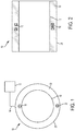
FIG. 1 is a schematic end view of a nozzle structure within an outer annular region of an aircraft engine; -
FIG. 2 is a schematic side, sectional view of the nozzle structure within the outer annular region of the aircraft engine; -
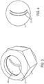
FIG. 3 is a perspective view of the nozzle structure; -
FIG. 4 is a sectional view of the nozzle structure ofFIG. 3 ; -
FIG. 5 is a sectional view of the nozzle structure according to another aspect of the disclosure; -
FIG. 6 is a sectional view of the nozzle structure according to another aspect of the disclosure; -
FIG. 7 is a sectional view of the nozzle structure according to another aspect of the disclosure; -
FIG. 8 is a sectional view of the nozzle structure according to another aspect of the disclosure; and -
FIG. 9 is a perspective view of the nozzle structure according to another aspect of the disclosure. - A detailed description of one or more embodiments of the disclosed apparatus and method are presented herein by way of exemplification and not limitation with reference to the Figures. The embodiments disclosed herein pertain to a nozzle structure used to distribute a fire extinguishing agent. In some embodiments, fire extinguishing systems utilized in aircraft engines particularly benefit from the nozzle structure disclosed herein. However, it is to be appreciated that other applications may employ the nozzle structure.
- Referring to
FIGS. 1 and 2 , a portion of anaircraft engine 10 is schematically illustrated. Theaircraft engine 10 includes one or more regions that include a fire extinguishing system to limit or eliminate a threat posed from a fire. The fire extinguishing system includes asupply housing 12 that is configured to contain a fire extinguishing agent. The fire extinguishing agent is routed through aline 14 that fluidly connects thesupply housing 12 to anozzle structure 16. In the illustrated embodiment, thenozzle structure 16 is located in anannular space 19 defined, at least partially, by anouter engine core 18 and a nacelle 20 (or cowl). However, it is to be appreciated that the location of thenozzle structure 16 may be located in other areas of theaircraft engine 10 to distribute the fire extinguishing agent to other locations, such as an auxiliary power unit (APU) compartment or bay. - Regardless of the location of the
nozzle structure 16, thesupply housing 12 may be located in close vicinity thereto or may be remotely located, such that theline 14 routes the fire extinguishing agent from one location of theaircraft engine 10 to the location of the nozzle structure, e.g., outside ofannular space 19 toannular space 19. - To avoid the issues with discharging non-gaseous fire extinguishing agents from circular openings at the end of a supply line, the embodiments disclosed herein include one or more
non-circular cross-sectional openings 22 to distribute the non-gaseous fire extinguishing agent. The fire extinguishing agent utilized with the disclosed embodiments is in a non-gaseous state. In some embodiments, the non-gaseous fire extinguishing agent is a dry chemical or aerosol agent used for suppressing fire. By describing the fire extinguishing agent as a "non-gaseous state" herein, it is to be understood that this phrase defines an agent that is not formed solely or substantially solely as a gas state agent. In other words, a liquid, a solid, a solid-liquid (2-phase) mixture or any other mixture of a gaseous and non-gaseous agent - even a 3-phase mixture - may be employed in various embodiments. - The
nozzle structure 16 coupled to, or integrally formed with, the end of theline 14 may have various structural geometries. As shown inFIG. 3 , a flat or slightlyrecessed nozzle structure 16 may be employed with the non-circular opening(s) 22 defined by aface 24 of thenozzle structure 16. Alternatively, as shown inFIG. 9 , ahead portion 26 of thenozzle structure 16 may be provided, with the non-circular opening(s) 22 defined by anouter surface 28 of thehead portion 26. The illustrated embodiments are merely examples and it is to be appreciated that other geometries of thenozzle structure 16 may be utilized. - In the case of a plurality of non-circular openings 22 (
FIG. 4 ) defined in thenozzle structure 16, the openings may be any suitable combination of holes, slots, apertures or the like, and may be arranged in any desirable orientation.FIGS. 3-8 illustrate various examples of non-circular openings, but it is to be understood that the illustrations and associated descriptions herein are not intended to be limiting, as several variants may be utilized based on the particular application of use. -
FIGS. 3 and 4 illustrate the non-circularopening 22 as an arc shaped slot. Alternatives include a semi-circular opening (FIG. 5 ), an L-shaped opening (FIG. 6 ), and a T-shaped opening (FIG. 7 ). Additionally, any combination of substantially linear - or planar - segments may be combined with any arc shaped segment. By way of example,FIG. 8 illustrates the non-circular opening as having a firstlinear segment 40, a secondlinear segment 42 oriented perpendicularly to the firstlinear segment 40, and an arc shapedsegment 44 extending from the secondlinear segment 42. In such an embodiment, the arc shapedsegment 44 could extend from the firstlinear segment 40 instead of the secondlinear segment 42, or two arc shaped segments may be included to have an arc shaped segment extending from each of the linear segments. It is to be appreciated that the illustrated perpendicular orientation is merely one example, as any angle between the segments may be employed in various embodiments. For example, the twolinear segments - In operation, energy losses are reduced when the non-gaseous agent contacts surfaces associated with the embodiments of the
nozzle structure 16 disclosed herein, when compared to a circular cross-sectional area opening. The various non-circular openings disclosed herein may be customized and optimized to match the contour of the region in which the fire extinguishing agent is being distributed. For example, a curved slot could have a geometry that matches the radius of the gap between the components defining theannular space 19 described above. Other more complicated shapes, or combinations of shapes, may be employed to distribute the agent between components. - Advantageously, the fire extinguishing agent can be distributed into a complex region with minimal impacts of the discharging agent on nearby components. By maintaining the energy of the discharging agent and gas, the distribution throughout the entire region is more efficient, thus minimizing the weight of the agent required to be stored.
- The term "about" is intended to include the degree of error associated with measurement of the particular quantity based upon the equipment available at the time of filing the application.
- The terminology used herein is for the purpose of describing particular embodiments only and is not intended to be limiting of the present disclosure. As used herein, the singular forms "a", "an" and "the" are intended to include the plural forms as well, unless the context clearly indicates otherwise. It will be further understood that the terms "comprises" and/or "comprising," when used in this specification, specify the presence of stated features, integers, steps, operations, elements, and/or components, but do not preclude the presence or addition of one or more other features, integers, steps, operations, element components, and/or groups thereof.
- The embodiments disclosed herein can be a system, a method, and/or a computer program product at any possible technical detail level of integration. The computer program product can include a computer readable storage medium (or media) having computer readable program instructions thereon for causing a processor to carry out aspects of the present disclosed embodiments.
- The computer readable storage medium can be a tangible device that can retain and store instructions for use by an instruction execution device. The computer readable storage medium can be, for example, but is not limited to, an electronic storage device, a magnetic storage device, an optical storage device, an electromagnetic storage device, a semiconductor storage device, or any suitable combination of the foregoing. A non-exhaustive list of more specific examples of the computer readable storage medium includes the following: a portable computer diskette, a hard disk, a random access memory (RAM), a read-only memory (ROM), an erasable programmable read-only memory (EPROM or Flash memory), a static random access memory (SRAM), a portable compact disc read-only memory (CD-ROM), a digital versatile disk (DVD), a memory stick, and any suitable combination of the foregoing. A computer readable storage medium, as used herein, is not to be construed as being transitory signals per se, such as radio waves or other freely propagating electromagnetic waves, electromagnetic waves propagating through a waveguide or other transmission media (e.g., light pulses passing through a fiber-optic cable), or electrical signals transmitted through a wire.
- Computer readable program instructions for carrying out operations of the disclosed embodiments can be assembler instructions, instruction-set-architecture (ISA) instructions, machine instructions, machine dependent instructions, microcode, firmware instructions, state-setting data, configuration data for integrated circuitry, or either source code or object code written in any combination of one or more programming languages, including an object oriented programming language such as Smalltalk, C++, or the like, and procedural programming languages, such as the "C" programming language or similar programming languages. The computer readable program instructions can execute entirely on the user's computer, partly on the user's computer, as a stand-alone software package, partly on the user's computer and partly on a remote computer or entirely on the remote computer or server. In the latter scenario, the remote computer can be connected to the user's computer through any type of network, including a local area network (LAN) or a wide area network (WAN), or the connection can be made to an external computer (for example, through the Internet using an Internet Service Provider). In some embodiments, electronic circuitry including, for example, programmable logic circuitry, field-programmable gate arrays (FPGA), or programmable logic arrays (PLA) can execute the computer readable program instructions by utilizing state information of the computer readable program instructions to personalize the electronic circuitry, in order to perform aspects of the disclosed embodiments.
- While the present disclosure has been described with reference to an exemplary embodiment or embodiments, it will be understood by those skilled in the art that various changes may be made and equivalents may be substituted for elements thereof without departing from the scope of the present disclosure. In addition, many modifications may be made to adapt a particular situation or material to the teachings of the present disclosure without departing from the essential scope thereof. Therefore, it is intended that the present disclosure not be limited to the particular embodiment disclosed as the best mode contemplated for carrying out this present disclosure, but that the present disclosure will include all embodiments falling within the scope of the claims.
Claims (14)
- An aircraft engine fire extinguishing system comprising:a supply housing (12) for containing a fire extinguishing agent;a line (14) for routing the fire extinguishing agent from the supply housing (12); anda nozzle structure (16) operatively coupled to the line (14), the nozzle structure (16) having a non-circular opening (22) for expelling the fire extinguishing agent.
- A method of distributing a fire extinguishing agent in an aircraft engine (10) comprising:routing a fire extinguishing agent from a supply housing (12) to a nozzle structure (16); andexpelling the fire extinguishing agent from the nozzle structure (16) through a non-circular opening (22) of the nozzle structure (16).
- The aircraft engine fire extinguishing system or method of claim 1 or 2, wherein the nozzle structure (16) is located within an annular space (19) defined by an engine core (18) and a nacelle (20).
- The aircraft engine fire extinguishing system or method of claim 1, 2 or 3, wherein the non-circular opening (22) is an arc shaped slot.
- The aircraft engine fire extinguishing system or method of claim 4, wherein the arc shaped slot is a semi-circular opening.
- The aircraft engine fire extinguishing system or method of claim 1, 2 or 3, wherein the non-circular opening (22) is an L-shaped opening.
- The aircraft engine fire extinguishing system or method of claim 1, 2 or 3, wherein the non-circular opening (22) is a T-shaped opening.
- The aircraft engine fire extinguishing system or method of claim 1, 2 or 3, wherein the non-circular opening (22) comprises a first linear segment (40), a second linear segment (42) oriented perpendicularly to the first linear segment (40), and an arc shaped segment (44) extending from one of the first linear segment (40) and the second linear segment (42).
- The aircraft engine fire extinguishing system or method of claim 1, 2 or 3, wherein the non-circular opening (22) comprises a first linear segment (40) and a second linear segment (42) oriented at a non-parallel angle to the first linear segment (40).
- The aircraft engine fire extinguishing system or method of any preceding claim, wherein the non-circular opening (22) is one of a plurality of non-circular openings (22) formed within the nozzle structure (16).
- The aircraft engine fire extinguishing system or method of any preceding claim, wherein at least a portion of the fire extinguishing agent is in a non-gaseous state.
- The aircraft engine fire extinguishing system or method of claim 11, wherein the non-gaseous fire extinguishing agent is at least one of a dry chemical or aerosol agent.
- The aircraft engine fire extinguishing system or method of any preceding claim, wherein the nozzle structure (16) is located within an auxiliary power unit compartment or bay.
- The aircraft engine fire extinguishing system or method of any preceding claim, wherein energy losses are reduced when the fire extinguishing agent contacts surfaces of the non-circular opening (22) compared to a circular opening.
Applications Claiming Priority (1)
| Application Number | Priority Date | Filing Date | Title |
|---|---|---|---|
| US16/103,478 US20200054907A1 (en) | 2018-08-14 | 2018-08-14 | Fire extinguishing agent nozzle structure |
Publications (2)
| Publication Number | Publication Date |
|---|---|
| EP3610925A1 true EP3610925A1 (en) | 2020-02-19 |
| EP3610925B1 EP3610925B1 (en) | 2022-11-23 |
Family
ID=67587483
Family Applications (1)
| Application Number | Title | Priority Date | Filing Date |
|---|---|---|---|
| EP19190721.1A Active EP3610925B1 (en) | 2018-08-14 | 2019-08-08 | Aircraft engine with fire extinguishing system |
Country Status (2)
| Country | Link |
|---|---|
| US (3) | US20200054907A1 (en) |
| EP (1) | EP3610925B1 (en) |
Families Citing this family (1)
| Publication number | Priority date | Publication date | Assignee | Title |
|---|---|---|---|---|
| US20200054907A1 (en) | 2018-08-14 | 2020-02-20 | Kidde Technologies, Inc. | Fire extinguishing agent nozzle structure |
Citations (6)
| Publication number | Priority date | Publication date | Assignee | Title |
|---|---|---|---|---|
| GB1157775A (en) * | 1968-02-22 | 1969-07-09 | Automatic Sprinkler Corp | Improvements in or relating to Spray Nozzle with Flat Fan Pattern |
| JPH09122537A (en) * | 1995-10-31 | 1997-05-13 | Nohmi Bosai Ltd | Fire extinguishing nozzle |
| WO2005018747A1 (en) * | 2003-08-22 | 2005-03-03 | Bronto Skylift Oy Ab | Method and equipment for fire-fighting |
| FR2877240A1 (en) * | 2004-10-29 | 2006-05-05 | Prevor Internat Sarl | LOW PRESSURE POWDER SPREADER WITH CONTROLLED FLOW |
| EP2764895A1 (en) * | 2011-10-05 | 2014-08-13 | Obschestvo S Ogranichennoy Otvetstvennostyou "Calancha" | Fire-extinguishing binary chemical condensation composition and a device for extinguishing fires |
| US20180161793A1 (en) * | 2016-10-07 | 2018-06-14 | Engineering & Scientific Innovations, Inc. | Smart multi-port fluid delivery system |
Family Cites Families (11)
| Publication number | Priority date | Publication date | Assignee | Title |
|---|---|---|---|---|
| US2340006A (en) * | 1940-08-02 | 1944-01-25 | Pyrene Mfg Co | Airplane fire extinguishing apparatus and method |
| US2647014A (en) * | 1952-07-25 | 1953-07-28 | Raleigh M Edwards | Sprinkler head |
| CA2222533C (en) | 1996-11-27 | 2006-09-05 | John G. Bureaux | Air aspirating foam nozzle |
| DE102006036762A1 (en) | 2006-08-05 | 2008-02-14 | Lindal Ventil Gmbh | spray nozzle |
| US8056837B2 (en) | 2008-04-25 | 2011-11-15 | Techtronic Outdoor Products Technology Limited | Nozzle for use with a pressure washer |
| US20120043096A1 (en) | 2010-03-09 | 2012-02-23 | Butz James R | Microemulsion Fire Protection Device and Method |
| JP6251050B2 (en) * | 2014-01-17 | 2017-12-20 | 三菱航空機株式会社 | Aircraft fire extinguishing equipment and aircraft |
| US10207133B2 (en) * | 2014-09-01 | 2019-02-19 | ESI Energy Solutions, LLC. | Smart nozzle delivery system |
| GB201510451D0 (en) * | 2015-06-15 | 2015-07-29 | The Technology Partnership Plc | Actuated-valve metering |
| US10232205B2 (en) | 2016-10-07 | 2019-03-19 | United Technologies Corporation | Multi-directional fire extinguishing nozzle |
| US20200054907A1 (en) | 2018-08-14 | 2020-02-20 | Kidde Technologies, Inc. | Fire extinguishing agent nozzle structure |
-
2018
- 2018-08-14 US US16/103,478 patent/US20200054907A1/en not_active Abandoned
-
2019
- 2019-08-08 EP EP19190721.1A patent/EP3610925B1/en active Active
-
2021
- 2021-10-08 US US17/497,590 patent/US11865384B2/en active Active
-
2023
- 2023-11-28 US US18/521,976 patent/US12296209B2/en active Active
Patent Citations (6)
| Publication number | Priority date | Publication date | Assignee | Title |
|---|---|---|---|---|
| GB1157775A (en) * | 1968-02-22 | 1969-07-09 | Automatic Sprinkler Corp | Improvements in or relating to Spray Nozzle with Flat Fan Pattern |
| JPH09122537A (en) * | 1995-10-31 | 1997-05-13 | Nohmi Bosai Ltd | Fire extinguishing nozzle |
| WO2005018747A1 (en) * | 2003-08-22 | 2005-03-03 | Bronto Skylift Oy Ab | Method and equipment for fire-fighting |
| FR2877240A1 (en) * | 2004-10-29 | 2006-05-05 | Prevor Internat Sarl | LOW PRESSURE POWDER SPREADER WITH CONTROLLED FLOW |
| EP2764895A1 (en) * | 2011-10-05 | 2014-08-13 | Obschestvo S Ogranichennoy Otvetstvennostyou "Calancha" | Fire-extinguishing binary chemical condensation composition and a device for extinguishing fires |
| US20180161793A1 (en) * | 2016-10-07 | 2018-06-14 | Engineering & Scientific Innovations, Inc. | Smart multi-port fluid delivery system |
Also Published As
| Publication number | Publication date |
|---|---|
| US20200054907A1 (en) | 2020-02-20 |
| US20240108924A1 (en) | 2024-04-04 |
| EP3610925B1 (en) | 2022-11-23 |
| US12296209B2 (en) | 2025-05-13 |
| US20220023689A1 (en) | 2022-01-27 |
| US11865384B2 (en) | 2024-01-09 |
Similar Documents
| Publication | Publication Date | Title |
|---|---|---|
| US20240108924A1 (en) | Fire extinguishing agent nozzle structure | |
| US10220802B2 (en) | Power source element detection and monitoring | |
| ES2726756T3 (en) | Prioritization of alternative landing facilities in flight planning | |
| US9902490B2 (en) | Intentionally imbalancing propellers for performance and noise-shaping | |
| CN103606302A (en) | Aircraft border-crossing management and control method and system | |
| JP2018043647A (en) | Unmanned aerial vehicle with glide function | |
| KR20190100204A (en) | Spray head with noise function for gas fire extinguishing equipment and storage and assembly method thereof | |
| US8064154B2 (en) | Device for protecting optical and/or electronic apparatuses, space telescope comprising said device, and device for removably occluding an aperture | |
| EP3036495A1 (en) | Multiple missile carriage and launch guidance module | |
| KR101099754B1 (en) | cable tray | |
| JP6996810B2 (en) | Bearing placement for electric swivels | |
| RU2734686C1 (en) | Control method of solid-propellant propulsion system of spacecraft and device for its implementation | |
| EP3702290B1 (en) | Liquid behavior suppression device | |
| CN114728685A (en) | Supporting structure of storage tank and ship | |
| CN103786902B (en) | Spacecraft electric thruster more changer adapter in-orbit | |
| JP7303959B2 (en) | Explosion-proof drone system | |
| CN105517900B (en) | It is placed on the shell structure between engine and the cabin with pivotal cover lid sector | |
| KR20170110198A (en) | Gas valve unit for controling gas supply | |
| US20140099876A1 (en) | Flow balancing ventilation system and method of balancing a flow | |
| EP3390223A1 (en) | Selecting propellers for performance and noise shaping | |
| CN219462407U (en) | Fire hydrant case spray gun head access instrument | |
| EP3041740A1 (en) | Case structure having connecting tabs | |
| KR101283926B1 (en) | Fan driving apparatus using fluid | |
| Gavranić et al. | Electrical Drives for Explosive Atmospheres: Motor Selection and Risk Assesment | |
| FR3134767B1 (en) | LIQUID CONTAINER(S) RECEPTION DEVICE WITH RETURN FORCE CONTROL, FOR VEHICLE EQUIPMENT |
Legal Events
| Date | Code | Title | Description |
|---|---|---|---|
| PUAI | Public reference made under article 153(3) epc to a published international application that has entered the european phase |
Free format text: ORIGINAL CODE: 0009012 |
|
| STAA | Information on the status of an ep patent application or granted ep patent |
Free format text: STATUS: THE APPLICATION HAS BEEN PUBLISHED |
|
| AK | Designated contracting states |
Kind code of ref document: A1 Designated state(s): AL AT BE BG CH CY CZ DE DK EE ES FI FR GB GR HR HU IE IS IT LI LT LU LV MC MK MT NL NO PL PT RO RS SE SI SK SM TR |
|
| AX | Request for extension of the european patent |
Extension state: BA ME |
|
| STAA | Information on the status of an ep patent application or granted ep patent |
Free format text: STATUS: REQUEST FOR EXAMINATION WAS MADE |
|
| 17P | Request for examination filed |
Effective date: 20200818 |
|
| RBV | Designated contracting states (corrected) |
Designated state(s): AL AT BE BG CH CY CZ DE DK EE ES FI FR GB GR HR HU IE IS IT LI LT LU LV MC MK MT NL NO PL PT RO RS SE SI SK SM TR |
|
| STAA | Information on the status of an ep patent application or granted ep patent |
Free format text: STATUS: EXAMINATION IS IN PROGRESS |
|
| 17Q | First examination report despatched |
Effective date: 20201209 |
|
| 17Q | First examination report despatched |
Effective date: 20210210 |
|
| GRAP | Despatch of communication of intention to grant a patent |
Free format text: ORIGINAL CODE: EPIDOSNIGR1 |
|
| STAA | Information on the status of an ep patent application or granted ep patent |
Free format text: STATUS: GRANT OF PATENT IS INTENDED |
|
| INTG | Intention to grant announced |
Effective date: 20220603 |
|
| RIN1 | Information on inventor provided before grant (corrected) |
Inventor name: SIMPSON, TERRY Inventor name: FAZZIO, MARK P. |
|
| GRAS | Grant fee paid |
Free format text: ORIGINAL CODE: EPIDOSNIGR3 |
|
| GRAA | (expected) grant |
Free format text: ORIGINAL CODE: 0009210 |
|
| STAA | Information on the status of an ep patent application or granted ep patent |
Free format text: STATUS: THE PATENT HAS BEEN GRANTED |
|
| AK | Designated contracting states |
Kind code of ref document: B1 Designated state(s): AL AT BE BG CH CY CZ DE DK EE ES FI FR GB GR HR HU IE IS IT LI LT LU LV MC MK MT NL NO PL PT RO RS SE SI SK SM TR |
|
| REG | Reference to a national code |
Ref country code: GB Ref legal event code: FG4D |
|
| REG | Reference to a national code |
Ref country code: CH Ref legal event code: EP |
|
| REG | Reference to a national code |
Ref country code: DE Ref legal event code: R096 Ref document number: 602019022150 Country of ref document: DE |
|
| REG | Reference to a national code |
Ref country code: AT Ref legal event code: REF Ref document number: 1532786 Country of ref document: AT Kind code of ref document: T Effective date: 20221215 |
|
| REG | Reference to a national code |
Ref country code: IE Ref legal event code: FG4D |
|
| REG | Reference to a national code |
Ref country code: LT Ref legal event code: MG9D |
|
| REG | Reference to a national code |
Ref country code: NL Ref legal event code: MP Effective date: 20221123 |
|
| REG | Reference to a national code |
Ref country code: AT Ref legal event code: MK05 Ref document number: 1532786 Country of ref document: AT Kind code of ref document: T Effective date: 20221123 |
|
| PG25 | Lapsed in a contracting state [announced via postgrant information from national office to epo] |
Ref country code: SE Free format text: LAPSE BECAUSE OF FAILURE TO SUBMIT A TRANSLATION OF THE DESCRIPTION OR TO PAY THE FEE WITHIN THE PRESCRIBED TIME-LIMIT Effective date: 20221123 Ref country code: PT Free format text: LAPSE BECAUSE OF FAILURE TO SUBMIT A TRANSLATION OF THE DESCRIPTION OR TO PAY THE FEE WITHIN THE PRESCRIBED TIME-LIMIT Effective date: 20230323 Ref country code: NO Free format text: LAPSE BECAUSE OF FAILURE TO SUBMIT A TRANSLATION OF THE DESCRIPTION OR TO PAY THE FEE WITHIN THE PRESCRIBED TIME-LIMIT Effective date: 20230223 Ref country code: LT Free format text: LAPSE BECAUSE OF FAILURE TO SUBMIT A TRANSLATION OF THE DESCRIPTION OR TO PAY THE FEE WITHIN THE PRESCRIBED TIME-LIMIT Effective date: 20221123 Ref country code: FI Free format text: LAPSE BECAUSE OF FAILURE TO SUBMIT A TRANSLATION OF THE DESCRIPTION OR TO PAY THE FEE WITHIN THE PRESCRIBED TIME-LIMIT Effective date: 20221123 Ref country code: ES Free format text: LAPSE BECAUSE OF FAILURE TO SUBMIT A TRANSLATION OF THE DESCRIPTION OR TO PAY THE FEE WITHIN THE PRESCRIBED TIME-LIMIT Effective date: 20221123 Ref country code: AT Free format text: LAPSE BECAUSE OF FAILURE TO SUBMIT A TRANSLATION OF THE DESCRIPTION OR TO PAY THE FEE WITHIN THE PRESCRIBED TIME-LIMIT Effective date: 20221123 |
|
| PG25 | Lapsed in a contracting state [announced via postgrant information from national office to epo] |
Ref country code: RS Free format text: LAPSE BECAUSE OF FAILURE TO SUBMIT A TRANSLATION OF THE DESCRIPTION OR TO PAY THE FEE WITHIN THE PRESCRIBED TIME-LIMIT Effective date: 20221123 Ref country code: PL Free format text: LAPSE BECAUSE OF FAILURE TO SUBMIT A TRANSLATION OF THE DESCRIPTION OR TO PAY THE FEE WITHIN THE PRESCRIBED TIME-LIMIT Effective date: 20221123 Ref country code: LV Free format text: LAPSE BECAUSE OF FAILURE TO SUBMIT A TRANSLATION OF THE DESCRIPTION OR TO PAY THE FEE WITHIN THE PRESCRIBED TIME-LIMIT Effective date: 20221123 Ref country code: IS Free format text: LAPSE BECAUSE OF FAILURE TO SUBMIT A TRANSLATION OF THE DESCRIPTION OR TO PAY THE FEE WITHIN THE PRESCRIBED TIME-LIMIT Effective date: 20230323 Ref country code: HR Free format text: LAPSE BECAUSE OF FAILURE TO SUBMIT A TRANSLATION OF THE DESCRIPTION OR TO PAY THE FEE WITHIN THE PRESCRIBED TIME-LIMIT Effective date: 20221123 Ref country code: GR Free format text: LAPSE BECAUSE OF FAILURE TO SUBMIT A TRANSLATION OF THE DESCRIPTION OR TO PAY THE FEE WITHIN THE PRESCRIBED TIME-LIMIT Effective date: 20230224 |
|
| PG25 | Lapsed in a contracting state [announced via postgrant information from national office to epo] |
Ref country code: NL Free format text: LAPSE BECAUSE OF FAILURE TO SUBMIT A TRANSLATION OF THE DESCRIPTION OR TO PAY THE FEE WITHIN THE PRESCRIBED TIME-LIMIT Effective date: 20221123 |
|
| P01 | Opt-out of the competence of the unified patent court (upc) registered |
Effective date: 20230603 |
|
| PG25 | Lapsed in a contracting state [announced via postgrant information from national office to epo] |
Ref country code: SM Free format text: LAPSE BECAUSE OF FAILURE TO SUBMIT A TRANSLATION OF THE DESCRIPTION OR TO PAY THE FEE WITHIN THE PRESCRIBED TIME-LIMIT Effective date: 20221123 Ref country code: RO Free format text: LAPSE BECAUSE OF FAILURE TO SUBMIT A TRANSLATION OF THE DESCRIPTION OR TO PAY THE FEE WITHIN THE PRESCRIBED TIME-LIMIT Effective date: 20221123 Ref country code: EE Free format text: LAPSE BECAUSE OF FAILURE TO SUBMIT A TRANSLATION OF THE DESCRIPTION OR TO PAY THE FEE WITHIN THE PRESCRIBED TIME-LIMIT Effective date: 20221123 Ref country code: DK Free format text: LAPSE BECAUSE OF FAILURE TO SUBMIT A TRANSLATION OF THE DESCRIPTION OR TO PAY THE FEE WITHIN THE PRESCRIBED TIME-LIMIT Effective date: 20221123 Ref country code: CZ Free format text: LAPSE BECAUSE OF FAILURE TO SUBMIT A TRANSLATION OF THE DESCRIPTION OR TO PAY THE FEE WITHIN THE PRESCRIBED TIME-LIMIT Effective date: 20221123 |
|
| REG | Reference to a national code |
Ref country code: DE Ref legal event code: R097 Ref document number: 602019022150 Country of ref document: DE |
|
| PG25 | Lapsed in a contracting state [announced via postgrant information from national office to epo] |
Ref country code: SK Free format text: LAPSE BECAUSE OF FAILURE TO SUBMIT A TRANSLATION OF THE DESCRIPTION OR TO PAY THE FEE WITHIN THE PRESCRIBED TIME-LIMIT Effective date: 20221123 Ref country code: AL Free format text: LAPSE BECAUSE OF FAILURE TO SUBMIT A TRANSLATION OF THE DESCRIPTION OR TO PAY THE FEE WITHIN THE PRESCRIBED TIME-LIMIT Effective date: 20221123 |
|
| PLBE | No opposition filed within time limit |
Free format text: ORIGINAL CODE: 0009261 |
|
| STAA | Information on the status of an ep patent application or granted ep patent |
Free format text: STATUS: NO OPPOSITION FILED WITHIN TIME LIMIT |
|
| 26N | No opposition filed |
Effective date: 20230824 |
|
| PG25 | Lapsed in a contracting state [announced via postgrant information from national office to epo] |
Ref country code: SI Free format text: LAPSE BECAUSE OF FAILURE TO SUBMIT A TRANSLATION OF THE DESCRIPTION OR TO PAY THE FEE WITHIN THE PRESCRIBED TIME-LIMIT Effective date: 20221123 |
|
| PG25 | Lapsed in a contracting state [announced via postgrant information from national office to epo] |
Ref country code: MC Free format text: LAPSE BECAUSE OF FAILURE TO SUBMIT A TRANSLATION OF THE DESCRIPTION OR TO PAY THE FEE WITHIN THE PRESCRIBED TIME-LIMIT Effective date: 20221123 |
|
| REG | Reference to a national code |
Ref country code: CH Ref legal event code: PL |
|
| PG25 | Lapsed in a contracting state [announced via postgrant information from national office to epo] |
Ref country code: MC Free format text: LAPSE BECAUSE OF FAILURE TO SUBMIT A TRANSLATION OF THE DESCRIPTION OR TO PAY THE FEE WITHIN THE PRESCRIBED TIME-LIMIT Effective date: 20221123 |
|
| PG25 | Lapsed in a contracting state [announced via postgrant information from national office to epo] |
Ref country code: LU Free format text: LAPSE BECAUSE OF NON-PAYMENT OF DUE FEES Effective date: 20230808 |
|
| PG25 | Lapsed in a contracting state [announced via postgrant information from national office to epo] |
Ref country code: LU Free format text: LAPSE BECAUSE OF NON-PAYMENT OF DUE FEES Effective date: 20230808 Ref country code: CH Free format text: LAPSE BECAUSE OF NON-PAYMENT OF DUE FEES Effective date: 20230831 |
|
| REG | Reference to a national code |
Ref country code: BE Ref legal event code: MM Effective date: 20230831 |
|
| REG | Reference to a national code |
Ref country code: IE Ref legal event code: MM4A |
|
| PG25 | Lapsed in a contracting state [announced via postgrant information from national office to epo] |
Ref country code: IT Free format text: LAPSE BECAUSE OF FAILURE TO SUBMIT A TRANSLATION OF THE DESCRIPTION OR TO PAY THE FEE WITHIN THE PRESCRIBED TIME-LIMIT Effective date: 20221123 |
|
| PG25 | Lapsed in a contracting state [announced via postgrant information from national office to epo] |
Ref country code: IE Free format text: LAPSE BECAUSE OF NON-PAYMENT OF DUE FEES Effective date: 20230808 |
|
| PG25 | Lapsed in a contracting state [announced via postgrant information from national office to epo] |
Ref country code: IE Free format text: LAPSE BECAUSE OF NON-PAYMENT OF DUE FEES Effective date: 20230808 |
|
| PG25 | Lapsed in a contracting state [announced via postgrant information from national office to epo] |
Ref country code: BE Free format text: LAPSE BECAUSE OF NON-PAYMENT OF DUE FEES Effective date: 20230831 |
|
| PG25 | Lapsed in a contracting state [announced via postgrant information from national office to epo] |
Ref country code: BG Free format text: LAPSE BECAUSE OF FAILURE TO SUBMIT A TRANSLATION OF THE DESCRIPTION OR TO PAY THE FEE WITHIN THE PRESCRIBED TIME-LIMIT Effective date: 20221123 |
|
| PG25 | Lapsed in a contracting state [announced via postgrant information from national office to epo] |
Ref country code: BG Free format text: LAPSE BECAUSE OF FAILURE TO SUBMIT A TRANSLATION OF THE DESCRIPTION OR TO PAY THE FEE WITHIN THE PRESCRIBED TIME-LIMIT Effective date: 20221123 |
|
| PG25 | Lapsed in a contracting state [announced via postgrant information from national office to epo] |
Ref country code: CY Free format text: LAPSE BECAUSE OF FAILURE TO SUBMIT A TRANSLATION OF THE DESCRIPTION OR TO PAY THE FEE WITHIN THE PRESCRIBED TIME-LIMIT; INVALID AB INITIO Effective date: 20190808 |
|
| PG25 | Lapsed in a contracting state [announced via postgrant information from national office to epo] |
Ref country code: HU Free format text: LAPSE BECAUSE OF FAILURE TO SUBMIT A TRANSLATION OF THE DESCRIPTION OR TO PAY THE FEE WITHIN THE PRESCRIBED TIME-LIMIT; INVALID AB INITIO Effective date: 20190808 |
|
| PGFP | Annual fee paid to national office [announced via postgrant information from national office to epo] |
Ref country code: DE Payment date: 20250724 Year of fee payment: 7 |
|
| PGFP | Annual fee paid to national office [announced via postgrant information from national office to epo] |
Ref country code: GB Payment date: 20250725 Year of fee payment: 7 |
|
| PGFP | Annual fee paid to national office [announced via postgrant information from national office to epo] |
Ref country code: FR Payment date: 20250725 Year of fee payment: 7 |
|
| PG25 | Lapsed in a contracting state [announced via postgrant information from national office to epo] |
Ref country code: TR Free format text: LAPSE BECAUSE OF FAILURE TO SUBMIT A TRANSLATION OF THE DESCRIPTION OR TO PAY THE FEE WITHIN THE PRESCRIBED TIME-LIMIT Effective date: 20221123 |