EP3610766A1 - Cleaning apparatus and control method for cleaning apparatus - Google Patents
Cleaning apparatus and control method for cleaning apparatus Download PDFInfo
- Publication number
- EP3610766A1 EP3610766A1 EP19182604.9A EP19182604A EP3610766A1 EP 3610766 A1 EP3610766 A1 EP 3610766A1 EP 19182604 A EP19182604 A EP 19182604A EP 3610766 A1 EP3610766 A1 EP 3610766A1
- Authority
- EP
- European Patent Office
- Prior art keywords
- cleaning
- unit
- camera
- detection surface
- cleaning apparatus
- Prior art date
- Legal status (The legal status is an assumption and is not a legal conclusion. Google has not performed a legal analysis and makes no representation as to the accuracy of the status listed.)
- Granted
Links
Images







Classifications
-
- A—HUMAN NECESSITIES
- A47—FURNITURE; DOMESTIC ARTICLES OR APPLIANCES; COFFEE MILLS; SPICE MILLS; SUCTION CLEANERS IN GENERAL
- A47L—DOMESTIC WASHING OR CLEANING; SUCTION CLEANERS IN GENERAL
- A47L1/00—Cleaning windows
- A47L1/02—Power-driven machines or devices
-
- B—PERFORMING OPERATIONS; TRANSPORTING
- B08—CLEANING
- B08B—CLEANING IN GENERAL; PREVENTION OF FOULING IN GENERAL
- B08B5/00—Cleaning by methods involving the use of air flow or gas flow
- B08B5/02—Cleaning by the force of jets, e.g. blowing-out cavities
-
- B—PERFORMING OPERATIONS; TRANSPORTING
- B08—CLEANING
- B08B—CLEANING IN GENERAL; PREVENTION OF FOULING IN GENERAL
- B08B1/00—Cleaning by methods involving the use of tools
- B08B1/10—Cleaning by methods involving the use of tools characterised by the type of cleaning tool
- B08B1/14—Wipes; Absorbent members, e.g. swabs or sponges
- B08B1/143—Wipes
-
- B—PERFORMING OPERATIONS; TRANSPORTING
- B08—CLEANING
- B08B—CLEANING IN GENERAL; PREVENTION OF FOULING IN GENERAL
- B08B13/00—Accessories or details of general applicability for machines or apparatus for cleaning
-
- G—PHYSICS
- G02—OPTICS
- G02B—OPTICAL ELEMENTS, SYSTEMS OR APPARATUS
- G02B27/00—Optical systems or apparatus not provided for by any of the groups G02B1/00 - G02B26/00, G02B30/00
- G02B27/0006—Optical systems or apparatus not provided for by any of the groups G02B1/00 - G02B26/00, G02B30/00 with means to keep optical surfaces clean, e.g. by preventing or removing dirt, stains, contamination, condensation
-
- G—PHYSICS
- G03—PHOTOGRAPHY; CINEMATOGRAPHY; ANALOGOUS TECHNIQUES USING WAVES OTHER THAN OPTICAL WAVES; ELECTROGRAPHY; HOLOGRAPHY
- G03B—APPARATUS OR ARRANGEMENTS FOR TAKING PHOTOGRAPHS OR FOR PROJECTING OR VIEWING THEM; APPARATUS OR ARRANGEMENTS EMPLOYING ANALOGOUS TECHNIQUES USING WAVES OTHER THAN OPTICAL WAVES; ACCESSORIES THEREFOR
- G03B17/00—Details of cameras or camera bodies; Accessories therefor
- G03B17/56—Accessories
Definitions
- the present invention relates to a cleaning apparatus for cleaning the detection surface of a detection element, which is arranged to detect a physical quantity of light, electromagnetic waves, or the like, and to a cleaning method for the cleaning apparatus.
- an image capturing surface (photoelectric conversion surface) of the image sensor is periodically cleaned to thereby prevent a deterioration in the quality of an image to be obtained.
- a user cleans the image capturing surface by himself/herself, there is a possibility that the image capturing surface may be accidentally damaged. Accordingly, in general, a user takes an image sensor to a service store, run by a manufacturer or the like, and asks a dedicated worker to clean the image capturing surface of the image sensor.
- Japanese Patent No. 04537105 discusses an apparatus that is connected to a camera so as to clean the front surface of an image capturing surface by wiping the surface using wind pressure or an adhesive sheet.
- cleaning apparatus as specified in claims 1 to 19.
- control method as specified in claim 20.
- Japanese Patent No. 04537105 described above fails to fully describe how to configure or control a cleaning apparatus to remove various types of foreign parties adhering to a detection surface.
- the issue that foreign particles adhering to the detection surface need to be removed is a common issue not only for image sensors, but also for general detection elements including a detection surface for detecting a physical quantity, and thus there is a long felt demand for such a cleaning apparatus.
- the present invention is directed to providing a cleaning apparatus capable of removing various types of foreign particles adhering to the detection surface of a detection element, and to a control method for the cleaning apparatus.
- Figs. 1A to 1C each illustrate a cleaning apparatus 100 as an example of a cleaning apparatus according to an exemplary embodiment of the present invention.
- a cleaning apparatus for cleaning an image capturing surface of an image sensor included in a digital camera and composed of a complementary metal-oxide semiconductor (CMOS) sensor is employed as an example.
- CMOS complementary metal-oxide semiconductor
- Fig. 1A illustrates an external view of the cleaning apparatus 100.
- the cleaning apparatus 100 includes a main body 1, which is formed of a metal chassis, a fixing unit 2 that fixes a detection apparatus (camera in the present exemplary embodiment) to be cleaned, and a display unit 7 that displays various types of information.
- the display unit 7 may be configured as a separate body that can communicate with the cleaning apparatus 100.
- Fig. 1B illustrates an internal configuration of the cleaning apparatus 100.
- a movable pedestal 6 is integrally provided with a check unit 3, a first cleaning unit 4, and a second cleaning unit 5.
- the movable pedestal 6 is translated and rotated in a three-dimensional direction, thereby making it possible to change the position of each unit, as needed.
- the movable pedestal 6 includes a translation mechanism that can be translated in a vertical direction so that each unit can approach the position of the fixing unit 2, i.e., to an image sensor surface after a camera 200 is attached and can retract toward the cleaning apparatus 100.
- the fixing unit 2 is composed of a ring-shaped metal member disposed on an exterior surface of the main body 1.
- the camera 200 to be cleaned has a structure in which a camera mount that enables an interchangeable lens to be attached to and detached from during normal use can be attached and fixed.
- the fixing unit 2 also includes an electrical connection terminal with which the fixing unit 2 can communicate with the attached camera 200.
- the fixing unit 2 includes a ring-shaped illumination lamp used for ensuring an amount of light necessary during monitoring a state of cleaning performed by the cleaning apparatus 100, and irradiates the detection element to be cleaned (image sensor of the camera 200) with light during cleaning the detection element by the first cleaning unit 4 and the second cleaning unit 5.
- an appropriate shape (mechanism) of a connection part of the fixing unit 2 varies depending on the type of an external apparatus to be attached.
- the fixing unit 2 may be configured to be attachable to and detachable from the main body 1, and the fixing unit 2 may be replaced depending on an external apparatus that is assumed to be connected.
- a number of fixing units 2 corresponding to the number of types of external apparatuses that are assumed to be connected may be provided.
- the fixing unit 2 may be provided as a general-purpose fixing mechanism capable of fixing the camera 200, regardless of the apparatus type.
- a connection terminal on the camera mount of the camera 200 to be attached is used to detect an attachment of the camera 200. More specifically, when the connection terminal of the fixing unit 2 is electrically connected to the connection terminal of the camera mount, the attachment of the camera 200 to the cleaning apparatus 100 is detected.
- the first cleaning unit 4 is a cleaning unit for performing non-contact cleaning on the surface of the detection element.
- air is blown to blow off foreign particles by wind pressure.
- the second cleaning unit 5 is a cleaning unit for performing contact cleaning on the surface of the detection element.
- foreign particles are cleaned off in a wipe cleaning operation using a wiping tool.
- Fig. 1C illustrates a rear side internal configuration of the cleaning apparatus 100.
- a cover is attached to an external case so as to cover each unit attached to an internal case.
- a control unit 10 is composed of a computer including a central processing unit (CPU).
- the control unit 10 controls the overall operation of the cleaning apparatus 100.
- the control unit 10 processes information received from each unit, and instructs each unit to execute processing.
- An air filter 11 is a filter that reduces foreign particles or oil present in the air when the air used for the first cleaning unit 4 is injected from an external pump or the like through an intake port 12. The air that has passed through the air filter 11 is supplied to the first cleaning unit 4. If the air filter 11 is omitted, there is a possibility that foreign particles included in the air may be blown toward the detection surface of the detection element.
- a pressure gauge 13 measures and displays the pressure of the air to be injected. A user can adjust the pressure of the air to an appropriate pressure, as needed, based on the pressure indicated by the pressure gauge 13.
- a power supply source 14 supplies power to the entire cleaning apparatus 100.
- the power supply source 14 may also have a function of feeding power to an external apparatus via an interface (e.g., electrical connection terminal of the fixing unit, communication unit 17, in the present exemplary embodiment).
- Fig. 2 illustrates the camera 200 as an example of an apparatus including the image sensor as the detection element to be cleaned.
- the camera 200 is a digital single-lens reflex camera of lens interchangeable type.
- a camera communication unit 24 includes, inside a cover, a connection terminal that complies with communication standards. The camera communication unit 24 performs communication in a state where the camera communication unit 24 is electrically connected to the cleaning apparatus 100 when the camera communication unit 24 is connected to the communication unit of the cleaning apparatus 100 with a cable such as a universal serial bus (USB).
- USB universal serial bus
- a camera control unit controls the lens and exchanges various types of information about the lens and the camera 200.
- An image sensor 22 receives object light and converts the received object light into an electrical signal to thereby generate digital image data.
- various types of sensors such as a charge-coupled device (CCD) type sensor and a charge injection device (CID) type sensor can also be used.
- CCD charge-coupled device
- ID charge injection device
- not only a light-receiving element, but also detection elements having any configuration can be used as a cleaning target of the cleaning apparatus 100, as long as the detection element includes a function for performing detection on a surface of an element, such as a detection element that detects an electromagnetic wave such as an X-ray.
- the image sensor 22 has a structure in which a cover glass, an infrared (IR) cut filter, and a low-pass filter (LPF) are stacked on a photodiode in a thickness direction.
- the cleaning apparatus 100 cleans the uppermost surface of the image sensor 22.
- a camera fixing unit 23 is connected to the fixing unit 2 of the cleaning apparatus 100, to thereby fix the camera 200.
- the control unit 10 can control the camera 200 by communicating with a camera control unit 21 via the communication unit 17 to be described below and the camera communication unit 24.
- the cleaning apparatus 100 can perform control for determination of the camera type, an image capturing operation to cause a mirror and a shutter provided on the camera 200 to move, and other operations.
- the second cleaning unit 5 is directed toward the fixing unit 2.
- the movable pedestal 6 includes the translation mechanism that can be translated in the vertical direction, which enables the second cleaning unit 5 to pass through the center of the ring of the fixing unit 2 and approach the image sensor 22 in a state where the camera 200 is physically connected.
- the movable pedestal 6 also includes a rotation mechanism that rotates an attached member.
- the check unit 3, the first cleaning unit 4, and the second cleaning unit 5 are arranged at positions with different phases about a rotation axis of the rotation mechanism.
- This rotation mechanism can drive to rotate the front surface of each of the check unit 3 and the first cleaning unit 4 to a position opposed to the fixing unit 2 (i.e., the image sensor surface of the image sensor 22), like the second cleaning unit 5.
- the translation mechanism can cause the one of the check unit 3 and the first cleaning unit 4 to approach to an image sensor surface 30, which is a detection surface, relative to the other one of the check unit 3 and the first cleaning unit 4, and after cleaning, the translation mechanism can cause the one of the check unit 3 and the first cleaning unit 4 to retract toward the cleaning apparatus 100.
- the rotation mechanism of the movable pedestal 6 is also used to control an inclination (controlling an angle) of the cleaning unit of each unit with respect to the detection surface in a cleaning sequence for each unit to be described below. More specifically, under the control of the control unit 10, the inclination of an injection port is controlled when the first cleaning unit 4 blows air toward the detection surface of the image sensor 22, and the inclination of the wiping tool (and a core) is controlled when the second cleaning unit 5 performs the wipe cleaning operation on the detection surface. As described above, using the translation mechanism and the rotation mechanism of the movable pedestal 6, the control unit 10 can control a distance from the detection surface, for example, by causing each unit to face, approach, and retract from the fixing unit 2, i.e., the detection surface of the detection element.
- the check unit 3 includes an illumination lamp and irradiates an object with illumination light in response to an instruction from the control unit 10.
- a light-emitting diode LED
- the image sensor 22 is irradiated with the light in an approached state.
- an image of the element surface (sensor surface) of the image sensor 22 is captured, and the captured image is used to acquire an image used to check the state of dirt on the surface.
- an image of the sensor surface is acquired using an image capturing function of the image sensor 22.
- the present invention is not limited to this example.
- the check unit 3 itself may acquire information based on which the state of the surface of the detection element including any sensor, such as an image sensor, can be checked.
- the check unit 3 is attached to the movable pedestal 6 together with the first cleaning unit 4 and the second cleaning unit 5.
- the check unit 3 may be fixed to a position near the fixing unit 2 and may be installed at the position.
- an illumination lamp and/or an image sensor may be provided as the check unit 3 in the vicinity of a cleaning member, such as an injection port, a wiping tool provided at a leading end of the core, of each of the first cleaning unit 4 and the second cleaning unit 5.
- the first cleaning unit 4 is a cleaning unit that performs non-contact cleaning on the detection element surface.
- air is blown from a leading end (injection port) of a cylindrical member, thereby blowing off foreign particles adhering to the surface of the approached image sensor 22 by wind pressure.
- the first cleaning unit 4 includes an ionizer having a neutralization function that is obtained by electrically charging the air so that foreign particles adhering to the surface of the image sensor 22 can be neutralized and easily removed.
- the ionizer need not necessarily be provided because a certain level of effect can be obtained only by blowing air without providing the neutralization function.
- the second cleaning unit 5 is a cleaning unit that performs contact cleaning on the detection element surface.
- foreign particles are cleaned off by directly wiping the surface of the approached image sensor 22 in the wipe cleaning operation using a wiping tool mainly attached to a leading end of the core.
- the wiping tool to be used include a microfiber cloth, paper, and tape.
- the second cleaning unit 5 is configured in such a manner that the second cleaning unit 5 comes into contact and moves to perform the wipe cleaning operation in a retractable manner and a new wiping tool contacts the cleaning surface. Further, in the present exemplary embodiment, the second cleaning unit 5 is also configured to perform cleaning by immersing the wiping tool in a solvent to remove grease, as needed.
- the specific configurations of the first cleaning unit 4 and the second cleaning unit 5 are not particularly limited, as long as the first cleaning unit 4 and the second cleaning unit 5 are a non-contact cleaning unit and a contact cleaning unit, respectively.
- Fig. 3 is a block diagram illustrating a main electrical configuration of each of the cleaning apparatus 100 and the camera 200 according to the present exemplary embodiment.
- the cleaning apparatus 100 operates with power supplied from the power supply source 14, and ON/OFF of the power supply source 14 is switched by a power supply SW 15.
- the display unit 7 displays various types of information about the cleaning apparatus 100 and the camera 200, and various types of information, such as an operation state, a setting made by a user operation, and a guidance for user operation, in response to an instruction from the control unit 10.
- An input unit 8 receives information about an external apparatus stored in a memory 16 or acquired through the communication unit 17 or another communication path, so that an appropriate operation can be performed depending on the camera 200 to be attached.
- the input unit 8 also receives information about various types of instructions by user operations.
- model information and specifications of the camera 200 to be connected are acquired through the input unit 8.
- a measurement unit 9 is composed of, for example, a laser distance meter, and measures the position (e.g., coordinates, a distance from the image sensor) and size of the image sensor 22 of the camera 200 to be connected. If the model information about the camera 200 to be attached is determined and the corresponding cleaning program is stored in the memory 16, there is no need to provide the measurement unit 9 to measure the position and size of the image sensor 22.
- the control unit 10, which is composed of a computer including a CPU incorporated in the main body 1 of the cleaning apparatus 100, controls the overall operation of the cleaning apparatus 100. The control unit 10 processes information from each unit, and instructs each unit to execute processing.
- connection terminal provided on the fixing unit 2 detects an electrical connection to connection terminals (lower part eight connection terminals in Fig. 2 ) of the camera fixing unit 23 when the camera fixing unit 23 is attached to the fixing unit 2, and the control unit 10 detects the connection of the camera 200.
- the communication unit 17 communicates with the detection apparatus including the detection element.
- the communication unit 17 is a connection terminal that complies with USB standards, and is electrically connected to the camera communication unit 24 of the camera 200 through a connection cable.
- the connection cable is connected to each terminal of the communication unit 17 and the camera communication unit 24 in a state where both the power supplies of the cleaning apparatus 100 and the camera 200 are ON, the cleaning apparatus 100 and the camera 200 are energized and communication is established between the cleaning apparatus 100 and the camera 200.
- the method for communication between the cleaning apparatus 100 and the camera 200 is not limited to this example.
- Known communication methods such as a wired local area network (LAN), a high-definition multimedia interface (HDMI®), and a wireless LAN (Wi-Fi®, Bluetooth®, Bluetooth® Low Energy) can also be used.
- the camera control unit 21 is a microcomputer, and controls the overall operation of the entire camera 200, such as operation control of the image sensor 22, storage of captured images, and data communication.
- the image sensor 22 is disposed at a position that is accessible through an opening formed in the camera mount, and includes a detection surface composed of a photodiode that receives a light beam from an object normally in a state where an image capturing lens is attached.
- the light beam received by the image sensor 22 is converted into an electrical signal and the electrical signal is output as image data.
- a mirror 25 is located on an optical axis at a location closer to the object than the image sensor 22 in the camera 200, and reflects or divides light to be transmitted to the image sensor 22 onto a sensor (not illustrated) other than the image sensor 22, an optical viewfinder, or the like. It is necessary to cause the mirror 25 to retract to a certain extent from the optical axis of the image sensor 22 during cleaning of the image sensor 22.
- the camera 200 uses a mechanism for causing the mirror 25 to retract from the optical axis during exposure of the image sensor 22 to cause the mirror 25 to retract from the optical axis to such an extent that a member from the cleaning apparatus 100 can approach the image sensor 22 during cleaning.
- the camera 200 serving as the detection apparatus is a digital single-lens reflex camera including the mirror 25.
- the present invention can be applied to a mirrorless single-lens camera, which includes no optical finder and no mirror.
- a light-shielding member (also referred to shutter) 26 is located at a location closer to the object than the image sensor 22 in the camera 200, and serves as a shutter that blocks light from being transmitted to the image sensor 22 during image capturing.
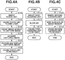
- Fig. 4A is a flowchart illustrating a check sequence for checking a state (dirt state, cleaning state) of the detection element surface to be cleaned by using the check unit 3.
- the control unit 10 performs each operation in the processing flow or instructs each unit to execute each operation, as needed.
- the camera 200 is already fixed to the cleaning apparatus 100 by the camera fixing unit 23 and the fixing unit 2, and the communication unit 17 establishes communication with the camera communication unit 24 to communicate with the camera 200 through a USB connection cable.
- step S100 the control unit 10 controls the movable pedestal 6 to direct the check unit 3 toward the fixing unit 2, and then causes the check unit 3 to move so as to pass through the fixing unit 2 and the camera fixing unit 23 and causes a leading end of the check unit 3 to approach the image sensor 22.
- step S101 in the vicinity of the image sensor 22, the check unit 3 irradiates the image sensor 22 with light by light emission of a point light source, such as an LED, which is provided at the leading end of the check unit 3.
- a point light source such as an LED
- the configuration of the illumination is not limited to a point light source, but instead any configuration can be applied. If the point light source is used, it is more desirable that uniform light is incident on each element and the state of the detection surface can be measured under substantially the same conditions. Therefore, the point light source is preferably used.
- the control unit 10 sends a signal to the camera control unit 21 through the communication unit 17 and the camera communication unit 24.
- the control unit 10 causes the image sensor 22 to perform the image capturing operation.
- the control unit 10 acquires the captured image.
- the acquired image is recorded on the memory 16 through the communication unit 17 and is converted into an image for display and displayed on the display unit 7.
- the control unit 10 detects, from the image that is captured and recorded, the state of the image sensor surface and information about foreign particles or dirt by a known image analysis method such as singularity detection for detecting a point at which the difference between a signal level of a target area and a signal level of a peripheral area is greater than a limit value, and displays the detected state and information, as well as the image, on the display unit 7.
- a known image analysis method such as singularity detection for detecting a point at which the difference between a signal level of a target area and a signal level of a peripheral area is greater than a limit value
- checking of an initial state of the image capturing surface, cleaning completion determination after cleaning, comparison and presentation before and after cleaning, and the like are performed.
- the comparison and presentation before and after cleaning are performed on the display unit 7 as the checking result, thereby making it possible to notify the user of the cleaning effect and information about remaining foreign particles.
- step S 105 the check unit 3 retracts toward the cleaning apparatus 100 from a location near the image sensor 22, and then the check sequence ends.
- Fig. 4D illustrates an example of a screen to be displayed on the display unit 7 in step S 104 in the check sequence after cleaning.
- a check image window 41 displays a part of a check image captured by the image sensor 22 in a state where the illumination by the check unit 3 is radiated.
- a foreign particle detection image window 42 displays a foreign particle image that corresponds to the check image displayed on the check image window 41 and is processed so as to easily detect and visually observe foreign particles by, for example, increasing the gain of the check image.
- a foreign particle information window 43 displays information about the detection result obtained after foreign particles are detected by the image analysis as described above. In the present exemplary embodiment, the number of foreign particles (five in Fig.
- each foreign particle detection range i.e., each area in which foreign particles are detected with a maximum value and a minimum value of X, Y coordinates of the detection surface of the detection element
- each foreign particle detection range may be displayed.
- An overall image window 44 displays a preview of the entire check image and the position of the check image currently displayed on the check image window 41 in a distinguishable manner. These windows allows the user to easily recognize the number, size, and position of foreign particles remaining on the image sensor 22 after cleaning.
- the check image obtained before cleaning and the foreign particle detection image are compared with information indicating the result of detecting foreign particles, thereby making it possible to check how cleaning is effective in removing foreign particles.
- the check image, the foreign particle detection image, and information about the result of detecting foreign particles, obtained through each check sequence are temporarily recorded on the memory 16, but instead a part or the whole of the images and information may be read out and transmitted to the camera 200 and then recorded on a memory or a recording medium in the camera 200.
- the control unit 10 may be connected to a server, and these pieces of information may be, for example, displayed, printed, or recorded by another apparatus via the server.
- Fig. 4B is a flowchart illustrating a first cleaning sequence for cleaning the surface of the detection surface by a non-contact cleaning method using the first cleaning unit 4.
- the control unit 10 performs each operation in the processing flow, as needed, or instructs each unit to execute each operation.
- the camera 200 is already fixed by the camera fixing unit 23 and the fixing unit 2 to the cleaning apparatus 100, and the communication unit 17 establishes communication with the camera communication unit 24 to communicate with the camera 200 through a USB connection cable.
- step S110 the control unit 10 controls the movable pedestal 6 to direct the first cleaning unit 4 toward the fixing unit 2 and further move to pass through the fixing unit 2 and the camera fixing unit 23, and then causes a portion (leading end) of the first cleaning unit 4 that is used for cleaning to approach the image sensor 22.
- step Sill the first cleaning unit 4 blows air from an injection port formed at the leading end thereof in the vicinity of the image sensor 22.
- the first cleaning unit 4 can remove, from the surface, foreign particles, such as solid foreign particles (relatively large particles) or dusts, which adhere to the image sensor surface 30 of the image sensor 22, by the blown air.
- foreign particles such as solid foreign particles (relatively large particles) or dusts
- the second cleaning unit 5 performs cleaning in a state where large solid foreign particles adhere to the image sensor surface 30
- the foreign particles carried during cleaning may damage the surface.
- foreign particles are not carried on the image sensor surface 30, which is advantageous in preventing damage to the surface.
- control unit 10 controls the movable pedestal 6 so as to prevent the first cleaning unit 4 from contacting the image sensor surface 30 of the image sensor 22 through the first cleaning sequence. This can further reduce possibility of damaging the image sensor surface 30 of the image sensor 22.
- the first cleaning unit 4 retracts from a location near the image sensor 22, and then the first cleaning sequence is terminated.
- Fig. 4E illustrates an example of a monitoring screen to be sequentially displayed on the display unit during cleaning in step Sill in the first cleaning sequence.
- a first monitoring screen 45 sequentially displays images obtained by successively capturing images of the state of cleaning performed by the first cleaning unit 4 in a state where an annular LED, which is attached to the fixing unit 2, is caused to emit light to irradiate the image sensor 22 with light.
- the air injection port of the first cleaning unit 4 is displayed as a shadow, and thus the location where the first cleaning unit 4 is currently cleaning can be checked.
- information indicating that the first cleaning sequence is currently performed is displayed ("Air" in Fig. 4E ) on the display screen.
- a point light source may be used as the illumination lamp attached to the fixing unit 2.
- a depth of field of an image obtained in this case increases, so that a clearer monitoring video image can be obtained.
- a remaining time until the end of the first cleaning sequence may also be displayed on the display screen.
- Fig. 4C is a flowchart illustrating a second cleaning sequence for performing contact cleaning on the surface of the detection element by using the second cleaning unit 5.
- the control unit 10 performs each operation in the processing flow on each unit, or instructs each unit to execute each operation, as needed.
- the camera 200 is already fixed to the cleaning apparatus 100 by the camera fixing unit 23 and the fixing unit 2, and the communication unit 17 establishes communication with the camera communication unit 24 to communicate with the camera 200 through a USB connection cable.
- step S120 the control unit 10 controls the movable pedestal 6 to direct the second cleaning unit 5 toward the fixing unit 2 and further move so as to pass through the fixing unit 2 and the camera fixing unit 23, and then causes a portion (leading end) of the second cleaning unit 5 that is used for cleaning to approach the image sensor 22.
- the movable pedestal 6 is controlled to dip the leading end of the second cleaning unit 5 in the solvent contained in a container that is provided at another rotation position, and then the second cleaning unit 5 is directed toward the fixing unit 2.
- step S121 the second cleaning unit 5 brings the leading end thereof into contact with the image sensor 22 in the vicinity of the image sensor 22, and then wipes the surface of the image sensor 22 with a wiping tool (cloth, paper, or the like) attached to the leading end thereof.
- a wiping tool cloth, paper, or the like
- the second cleaning unit 5 can remove, from the surface of the image sensor 22, dirt such as foreign particles or highly adhesive oil adhering to the surface of the image sensor 22.
- step S 122 the second cleaning unit 5 retracts from a location near the image sensor 22, and then the second cleaning sequence is terminated.
- Fig. 4F illustrates an example of a monitoring screen displayed on the display unit 7 during cleaning in step S121 in the second cleaning sequence.
- a second monitoring screen 46 displays images obtained by successively capturing images of the state of cleaning performed by the second cleaning unit 5 in a state where an annular LED, which is attached to the fixing unit 2, is caused to emit light to irradiate the image sensor 22 with light.
- the wiping tool of the second cleaning unit 5 is displayed as a shadow, and thus the location where the second cleaning unit 5 is currently cleaning can be checked. Further, information indicating that the second cleaning sequence is currently performed ("Wipe" in Fig. 4F ) is displayed on the display screen. In addition, a remaining time until the end of the second cleaning sequence may also be displayed on the display screen.
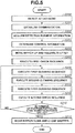
- This processing flow is started, for example, when the power supply source 14 is turned on by operating the power supply SW 15, or when an instruction for stating a cleaning step is received from the input unit 8.
- the control unit 10 performs each operation in the processing flow, or instructs each unit to execute each operation.
- Figs. 6A to 6E each illustrate an example of a display screen displayed on the display unit 7 during execution of each processing flow illustrated in Fig. 5 , or before and after the execution of each processing flow illustrated in Fig. 5 .
- Fig. 6A is a display screen for performing a guide display that is displayed by the control unit 10 on the display unit 7 before the processing flow is started and is used to guide an operation when the cleaning sequence is executed.
- An attachment guide display 61 performs the following three guide display operations:
- step S200 the control unit 10 uses the connection terminal provided on the fixing unit 2 to detect that the camera fixing unit 23 of the camera 200 is attached and fixed to the fixing unit 2.
- step S201 the control unit 10 detects that the communication unit 17 and the camera communication unit 24 are electrically connected, and upon detecting the electrical connection, the control unit 10 establishes communication between the cleaning apparatus 100 and the camera 200.
- the control unit 10 acquires detection element information about the detection element to be cleaned.
- the detection element information include information about the position, size, and material of the image sensor 22, and the position of a member that interferes with cleaning of the image sensor 22. These pieces of information may be acquired by the camera 200 through communication, or the detection element information may be read out from a database preliminarily stored in the memory 16 based on camera model information acquired from the camera 200. Alternatively, the detection element information or the model information about the camera 200 may be acquired by a user input through the input unit 8. In the exemplary embodiment in which the check unit 3 is provided with a sensor for detecting the state of the image sensor 22, in step 202, the detection element information is acquired based on, for example, information about an image detected by the check unit 3.
- step S203 the control unit 10 determines control information based on the detection element information about the image sensor 22 obtained in step S202. More specifically, based on the information about the position and size of the image sensor 22, a driving range when the check unit 3, the first cleaning unit 4, and the second cleaning unit 5 are caused to move forward or backward by using the movable pedestal 6 is determined, and the distance from the detection surface is controlled. Further, an air injection position or an injection strength of the first cleaning unit 4, a wipe cleaning range of the second cleaning unit 5, whether to use a solvent to be applied to the wiping tool, and the like are determined.
- a plurality of cleaning courses using at least one of the first cleaning unit 4 and the second cleaning unit 5 is prepared, and the user can select a cleaning course from among, for example, a plurality of candidates displayed on the display unit 7 in consideration of a dirt state, an operation time, and the like.
- the following cleaning courses are prepared.
- the subsequent processing flow will be described assuming that Course 1 is selected. However, if a course other than Course 1 is selected, steps unnecessary for the selected course may be omitted as needed (without performing any operation).
- Settable courses are not limited to these examples, but instead courses prepared by the user by arbitrarily setting various sequences may be provided.
- control unit 10 prepares a plurality of patterns of combinations in advance, or manually receives a setting for a combination of cleaning performed by the first cleaning unit 4 and cleaning performed by the second cleaning unit 5. Based on the received setting, a cleaning order and/or the number of cleaning operations performed by the first cleaning unit 4 and the cleaning performed by the second cleaning unit 5 is controlled to clean the detection surface.
- Fig. 6B illustrates a display example of a selection screen for selecting a combination (course) of cleaning sequences.
- a course display 62 is a graphical user interface (GUI) with which examples of a combination of a plurality of patterns prepared in advance can be displayed in a comparable manner and selected.
- GUI graphical user interface
- different courses are prepared depending on whether to use a solvent at a time of the wipe cleaning operation performed by the second cleaning unit 5.
- a calibration source for calibration of each cleaning unit is also provided.
- other courses as described below, including courses other than those illustrated in the drawings, can be employed.
- An estimated time required to complete each course may be displayed on the course display 62.
- a state display 63 is an area in which the control unit 10 displays cleaning apparatus information indicating a state of the cleaning apparatus 100.
- the cleaning apparatus information include the remaining length of the wiping tool of the second cleaning unit 5, the remaining number of cleaning operations, the temperature of the control unit 10, and the temperature in the vicinity of the cleaning area (near the detection surface).
- the display of these pieces of cleaning apparatus information enables the user to provide information to support the execution of cleaning, such as cleaning of each camera, for example, in consideration of the remaining number of cleaning operations.
- a state display 64 is an area in which the control unit 10 displays the state of the camera 200.
- the detection element information about the detection apparatus include a previous number of cleaning operations, a date and time when cleaning is performed, and camera model information as information for specifying the detection element.
- the display of these pieces of detection element information enables the user to, for example, check the model to be cleaned, or recognize the when and how many cleaning operations are performed in the past. Accordingly, it is possible to provide information to support the user to, for example, cancel cleaning if an erroneous camera is set as a cleaning target, or if a cleaning cycle is extremely short.
- step S204 to execute various sequences on the image sensor 22, the control unit 10 transmits a signal to instruct the camera control unit 21 to move the mirror 25 up and release a shutter 26.
- the camera control unit 21 Upon receiving the instruction signal to move the mirror 25 up and releasing the shutter 26, the camera control unit 21 causes the mirror 25 to move up and causes the shutter 26 to be released, and then transmits a signal indicating that the operation is completed to the control unit 10.
- the processing which has received the signal proceeds to step S205.
- the image sensor 22 is not shielded and cleaning can be performed without carrying out step S204. In this case, step 204 and step S211 that is described below can be omitted.
- step S205 the control unit 10 executes the check sequence illustrated in Fig. 4A as a first check sequence to be performed before cleaning.
- step S206 the control unit 10 performs the first cleaning sequence using the first cleaning unit 4 as illustrated in Fig. 4B .
- step S207 the control unit 10 performs a second cleaning sequence using the second cleaning unit 5 as illustrated in Fig. 4C .
- the first cleaning sequence is carried out before the second cleaning sequence. This is because large foreign particles needs to be removed in advance in the first cleaning sequence to prevent large foreign particles, adhering to the image sensor surface 30 and carried in the wipe cleaning operation performed by the second cleaning unit 5, from damaging the surface.
- step S208 the control unit 10 performs the first cleaning sequence using the first cleaning unit 4 again.
- the operation in the sequence may be the same as that in step S206, or may be different from that in step S206.
- the first cleaning sequence is carried out after the second cleaning sequence. This is because fibers of the wiping tool may remain on the image sensor surface 30 during the wipe cleaning operation performed by the second cleaning unit 5, or foreign particles pushed out of the image sensor surface 30 may remain in the vicinity of the image sensor surface 30. If the first cleaning sequence is carried out after the second cleaning sequence, these foreign particles can be blown off and cleaned.
- step S209 the second check sequence after cleaning as illustrated in Fig. 4A is performed.
- the second check sequence differs from the first check sequence performed before cleaning in that images obtained before and after cleaning and the state such as the number of foreign particles can be displayed on the display unit 7 in a comparable manner in step S104.
- step S210 it is determined whether the number of foreign particles is less than a prescribed value based on information after cleaning about the image acquired in step S209. If the number of foreign particles is not less than the prescribed value (NO in step S210), the processing returns to step S206 to perform cleaning again. In this case, to remove foreign particles remaining even after each cleaning sequence is performed once, each cleaning sequence may be performed again after changing various types of parameters for cleaning.
- the first cleaning unit 4 may set the air injection strength to be higher than before, set the degree of charging by the ionizer to be higher than before, set the injection time to be longer than before, or set a movement range to be wider than before.
- the second cleaning unit 5 may dip the wiping tool in a solvent if the wiping tool is not dipped in the solvent in the previous cleaning operation, or set a contact pressure on the image sensor surface 30 to be higher than before.
- step S210 if the number of foreign particles is less than the prescribed value (YES in step S210), the processing proceeds to step S211.
- step S211 the control unit 10 transmits a signal to instruct the camera control unit 21 to move the mirror 25 down and close the shutter 26.
- the camera control unit 21, which has received the instruction signal to move the mirror 25 down and close the shutter 26, causes the mirror 25 to move down and causes the shutter 26 to be closed, and then transmits a signal indicating that the operation is completed to the control unit 10. Then, the control unit 10, which has received the signal, terminates the cleaning sequence.
- step S210 the number of foreign particles remaining on the image sensor 22 is detected to check the cleaning state.
- the present invention is not limited to this example.
- Other analysis results may be used as criteria, as long as the results indicate the state of the image sensor 22 that can be analyzed based on an image.
- an example in which each cleaning sequence is repeatedly performed until the number of foreign particles is less than the prescribed value is described as an example.
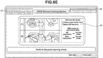
- Fig. 6E illustrates a display screen displayed by the control unit 10 on the display unit 7 when the processing flow illustrated in Fig. 5 is finished, and used to perform a guide display to guide an operation to be performed when the use of the cleaning apparatus 100 is terminated.
- a detachment guide display 65 performs the following two guide display operations:
- Fig. 7 is a front schematic view illustrating the cleaning apparatus 100 according to the present exemplary embodiment.
- the main body 1 includes at least two housings.
- a first housing 51 which is one of the two housings, includes the fixing unit 2, the check unit 3, the first cleaning unit 4, the second cleaning unit 5, and the movable pedestal 6, which are members directly related mechanically to each cleaning unit or the cleaning operation of cleaning unit.
- the control unit 10 and the air filter 11 are attached to the first housing 51 on the rear surface thereof.
- the other housing i.e., a second housing 52 includes components that are not directly related to the cleaning operation of cleaning unit, such as the display unit 7, a fee-payment unit 60, and a movement assist unit 70, and that is connected to the first housing 51 via a support member 53 and supports the first housing 51.
- the fee-payment unit 60 is used for the user to pay fees for usage of services, such as a cleaning service using the cleaning apparatus 100, or receive the fee, when the cleaning apparatus 100 according to the present exemplary embodiment is installed in a store or the like.
- the movement assist unit 70 includes wheels for moving the entire cleaning apparatus 100, typified by a caster, and facilitates the movement of the entire cleaning apparatus 100.
- the first housing 51 is surrounded by the second housing 52 and is elastically supported by the second housing 52 via the support member 53, which is made of hard vinyl chloride, in the gravity direction and the horizontal direction. Further, the first housing 51 is formed of a member or shape with a rigidity higher than that of the second housing 52. With this configuration, even when an external force from the outside of the cleaning apparatus 100 is received by the second housing 52, the force is dispersed due to the rigidity of the second housing 52 and the elastic force of the support member 53, so that the first housing 51 is less likely to be deformed. As a result, an advantageous effect that adverse effects on the cleaning operation are reduced, can be obtained.
- the fixing unit 2 illustrated in Fig. 7 is directly supported by the first housing 51 and is configured so as to project from the second housing 52. With this configuration, if a grip portion 27, which projects toward the camera 200, is provided, the fixing unit 2 can be connected to the cleaning apparatus 100 without causing any problem. Further, since the camera 200 is directly supported by the first housing 51 via the fixing unit 2, even when an external force is applied to, especially, the second housing 52 of the cleaning apparatus 100, the force is less likely to be applied to the components that are directly related to cleaning, and thus adverse effects of the external force on the cleaning configuration and the cleaning operation can be reduced.
- the fixing unit 2 need not necessarily project toward the second housing 52, and may have any configuration as long as the circumferential portion of the fixing unit 2 is formed relatively low not to prevent the grip portion 27 from attaching to the fixing unit 2.
- Figs. 8A to 8D illustrate configuration examples of the fixing unit 2, the check unit 3, the first cleaning unit 4, and the second cleaning unit 5, respectively, according to the present exemplary embodiment.
- Fig. 8A is an external perspective view of the fixing unit 2.
- the fixing unit 2 is provided with a mount portion having a shape matching the camera 200 to be connected to an upper portion of a base, which is formed in a tapered shape or a truncated cone shape.
- the mount portion is provided with a connection terminal capable of detecting a connection with the camera 200 and communicating with the camera 200, like an interchangeable lens or the like to be connected to a general camera.
- an annular illumination member is also provided on the back side of the base, and this illumination member is used to monitor the cleaning state based on an output from the image sensor 22 by irradiating the sensor surface with light during cleaning.
- the fixing unit 2 may be detachably attached to the first housing 51, and may be configured to be replaced with the fixing unit 2 including a mount that is compatible with different manufacturers or models of cameras to be cleaned.
- Fig. 8B illustrates a configuration example of the check unit 3.
- the check unit 3 has a configuration in which a bar-like support member fixed to the movable pedestal 6 and including a wire is provided with a point light source (with a small hole formed at a cylindrical leading end (upper surface) covering the light source), such as an LED, so that light is irradiated on an extension of the support member.
- a point light source with a small hole formed at a cylindrical leading end (upper surface) covering the light source
- Fig. 8C illustrates a configuration example of the first cleaning unit 4.
- the first cleaning unit 4 includes a cylindrical injection port, and blows air from a leading end thereof. As described above, the air is injected into the air filter 11 from an external pump or the like through the intake port 12, and the air is supplied to the first cleaning unit 4 through a pipe disposed in the cleaning apparatus 100 in a state where foreign particles or oil is reduced.
- Fig. 8D illustrates a configuration example of the second cleaning unit 5.
- a base plate 80 is provided with a fiber tape 81 including woven microfibers used to wipe off foreign particles, a winding portion 82 around which the fiber tape 81 is wound, a feed portion 83 for feeding the fiber tape 81, and a gear portion 84 for controlling the amount of winding of the tape.
- a leading end core portion 86 which is formed of metal, is attached to a leading end of a core 85, and an elastic member 87 urges the core 85 in a driving direction.
- a vibrator 88 applies vibration to the leading end core portion 86.
- a roller 89 is a member formed of metal and comes into contact with the core 85 to regulate the movement of the core 85 in the driving direction.
- a guide member 90 is a member that regulates the movement of the fiber tape 81 and is molded with resin.
- the vibrator 88 generates vibration by a piezoelectric element or an actuator and provides the leading end core portion 86 with micro-vibration in a Z-direction during the cleaning operation, thereby making it possible to reduce a frictional force generated between the fiber tape 81 and the image sensor surface 30 and achieve a smooth cleaning operation. Further, since the vibration generated by the vibrator 88 reduce frictional force with the fiber tape 81, the guide member 90, and the leading end core portion 86, a smooth winding operation can be performed also during winding of the fiber tape 81.
- the fiber tape 81 is wound by the gear portion 84 while the fiber tape 81 is caught in the gear portion 84, and an unused portion of the fiber tape 81 is drawn from the feed portion 83 and used for cleaning at the leading end core portion 86.
- a used portion of the fiber tape 81 is wound around the winding portion 82.
- the movement of the fiber tape 81 is regulated by the guide member 60, and the fiber 81 is wound while the state where the fiber tape 81 is laid on the leading end core portion 86 is maintained.
- the fiber tape 81 that is laid on the leading end core portion 86 is pressed against the image sensor 11 and the operation of wiping off foreign particles is carried out.
- the core 85 can be caused to slide in a pressing direction (Z-direction in Fig. 4D ), and cleaning is performed by appropriate pressing while squashing the elastic member 87. Since an appropriate pressing force is applied to the image sensor surface 30 by the elastic member 87, foreign particles can be removed without damaging the image sensor 11. Further, the metallic roller 89 is in contact with the core 85 also during movement, so that the electrical connection between the camera communication unit 24 and the core 85 is ensured via the metallic roller 89.
- the vibrator 88 attached to an upper portion of the core 85 vibrates the core 85, thereby reducing the frictional force between the fiber tape 81 and the image sensor surface 30, which are pressed against each other, and achieving a smooth cleaning operation while preventing the fiber tape 81 from being caught on the image sensor surface 30.
- the cleaning apparatus that receives a setting for a combination of cleaning operations to be performed by a plurality of different types of cleaning units, and controls the cleaning order and the number of cleaning operations of each cleaning unit based on the received setting, to thereby clean the detection surface. Consequently, it is possible for the user to clean the detection apparatus with a simple operation.
- cleaning by the second cleaning unit that performs wipe cleaning in a contact state is performed, after cleaning is performed by the first cleaning unit that performs cleaning by wind pressure (injection) on the detection surface of the detection element that detects a physical quantity.
- various types of foreign particles adhering to the detection surface can be appropriately removed.
- cleaning in a non-contact manner is performed again after wipe cleaning, thereby making it possible to remove fibers of the wiping tool attached during the wipe cleaning operation, foreign particles remaining after cleaning, and foreign particles present at the periphery of the detection surface.
- images of the detection surface are obtained by capturing images of the detection surface before or after cleaning, or before and after cleaning, which makes it possible to check the state of the detection surface before or after cleaning, or before and after cleaning.
- the use of a point light source as the light source that irradiates the detection surface with light makes it possible to acquire images that have a deeper depth of field and facilitate the recognition of foreign particles. Therefore, foreign particles remaining on the detection surface can be visually observed or detected easily.
- the state of foreign particles can be analyzed by analyzing the captured images of the detection surface, and thus it is possible to present the number of foreign particles and perform display with enhanced visibility for foreign particles.
- the cleaning apparatus including a plurality of cleaning units capable of performing a plurality of cleaning sequences can remove various types of foreign particles adhering to the detection surface of the detection apparatus including the detection element.
- a storage medium storing a software program code in which procedures for implementing the functions according to the exemplary embodiments described above are described is supplied to a system or apparatus. Then, a computer (or a CPU, a microprocessor unit (MPU), etc.) of the system or apparatus reads out the program code stored in the storage medium and executes the program code.
- a computer or a CPU, a microprocessor unit (MPU), etc.
- the program code read from the storage medium implements new functions according to the present invention
- the storage medium storing the program code and the program constitute the present invention.
- Examples of the storage medium for supplying the program code include a flexible disk, a hard disk, an optical disk, and a magneto-optical disk.
- a compact disc read-only memory (CD-ROM), a CD-recordable (CD-R), CD-rewritable (CD-RW), a digital versatile disc (DVD)-ROM, a DVD-random access memory (RAM), a DVD-RW, a DVD-R, a magnetic tape, a nonvolatile memory card, a ROM, and the like can also be used.
- the program code read by the computer can be executed to thereby implement the functions according to the exemplary embodiments described above.
- the present invention also includes a case where a part or the whole of actual processing is executed by an operating system (OS) or the like that runs on the computer based on an instruction from the program code, and the processing implements the functions according to the exemplary embodiments described above.
- OS operating system
- the present invention also includes the following cases.
- Embodiment(s) of the present invention can also be realized by a computer of a system or apparatus that reads out and executes computer executable instructions (e.g., one or more programs) recorded on a storage medium (which may also be referred to more fully as a 'non-transitory computer-readable storage medium') to perform the functions of one or more of the above-described embodiment(s) and/or that includes one or more circuits (e.g., application specific integrated circuit (ASIC)) for performing the functions of one or more of the above-described embodiment(s), and by a method performed by the computer of the system or apparatus by, for example, reading out and executing the computer executable instructions from the storage medium to perform the functions of one or more of the above-described embodiment(s) and/or controlling the one or more circuits to perform the functions of one or more of the above-described embodiment(s).
- computer executable instructions e.g., one or more programs
- a storage medium which may also be referred to more fully as
- the computer may comprise one or more processors (e.g., central processing unit (CPU), micro processing unit (MPU)) and may include a network of separate computers or separate processors to read out and execute the computer executable instructions.
- the computer executable instructions may be provided to the computer, for example, from a network or the storage medium.
- the storage medium may include, for example, one or more of a hard disk, a random-access memory (RAM), a read only memory (ROM), a storage of distributed computing systems, an optical disk (such as a compact disc (CD), digital versatile disc (DVD), or Blu-ray Disc (BD)TM), a flash memory device, a memory card, and the like.
Landscapes
- Physics & Mathematics (AREA)
- General Physics & Mathematics (AREA)
- Optics & Photonics (AREA)
- Accessories Of Cameras (AREA)
- Studio Devices (AREA)
Abstract
Description
- The present invention relates to a cleaning apparatus for cleaning the detection surface of a detection element, which is arranged to detect a physical quantity of light, electromagnetic waves, or the like, and to a cleaning method for the cleaning apparatus.
- There is an issue with such detection elements that erroneous detection can occur due to foreign particles adhering to the detection surface of the detection element. In a digital camera including an image sensor having a configuration in which photoelectric converters serving as light-receiving elements are two-dimensionally arranged, an image capturing surface (photoelectric conversion surface) of the image sensor is periodically cleaned to thereby prevent a deterioration in the quality of an image to be obtained. However, if a user cleans the image capturing surface by himself/herself, there is a possibility that the image capturing surface may be accidentally damaged. Accordingly, in general, a user takes an image sensor to a service store, run by a manufacturer or the like, and asks a dedicated worker to clean the image capturing surface of the image sensor. However, the accuracy of cleaning work varies depending on the differences in the proficiency level of such workers. In this regard, Japanese Patent No.
04537105 - According to a first aspect of the present invention, there is provided cleaning apparatus as specified in
claims 1 to 19. According to a second aspect of the present invention, there is provided a control method as specified in claim 20. - Further features of the present invention will become apparent from the following description of exemplary embodiments with reference to the attached drawings. Each of the embodiments of the present invention described below can be implemented solely or as a combination of a plurality of the embodiments. Also, features from different embodiments can be combined where necessary or where the combination of elements or features from individual embodiments in a single embodiment is beneficial.
-
-
Figs. 1A, 1B, and 1C are diagrams illustrating an external view, a perspective view of internal configuration, and a rear side internal configuration of a cleaning apparatus according to an exemplary embodiment of the present invention. -
Fig. 2 is a diagram illustrating a front view of an image capturing apparatus according to the exemplary embodiment. -
Fig. 3 is a block diagram illustrating a configuration of a main part of each of the cleaning apparatus and the image capturing apparatus according to the exemplary embodiment. -
Figs. 4A, 4B, and 4C are flowcharts each illustrating a sequence of the cleaning apparatus according to the exemplary embodiment, andFigs. 4D, 4E, and 4F are diagrams each illustrating an example of a screen to be displayed on a display unit according to the exemplary embodiment. -
Fig. 5 is a flowchart illustrating a series of cleaning sequences according to the exemplary embodiment. -
Figs. 6A ,6B ,6C, 6D , and6E are diagrams each illustrating a display screen in the series of cleaning sequences according to the present exemplary embodiment. -
Fig. 7 is a diagram illustrating a configuration example of the cleaning apparatus according to the exemplary embodiment. -
Figs. 8A, 8B, 8C, and 8D are diagrams illustrating configuration examples of a fixing unit, a check unit, a first cleaning unit, and a second cleaning unit, respectively, according to the exemplary embodiment. - Exemplary embodiments of the present invention will be described in detail below with reference to the accompanying drawings. Throughout the drawings, the same or similar parts are denoted by the same reference numerals.
- Japanese Patent No.
04537105 -
Figs. 1A to 1C each illustrate acleaning apparatus 100 as an example of a cleaning apparatus according to an exemplary embodiment of the present invention. In the present exemplary embodiment, a cleaning apparatus for cleaning an image capturing surface of an image sensor included in a digital camera and composed of a complementary metal-oxide semiconductor (CMOS) sensor, is employed as an example. -
Fig. 1A illustrates an external view of thecleaning apparatus 100. Thecleaning apparatus 100 includes amain body 1, which is formed of a metal chassis, afixing unit 2 that fixes a detection apparatus (camera in the present exemplary embodiment) to be cleaned, and adisplay unit 7 that displays various types of information. Thedisplay unit 7 may be configured as a separate body that can communicate with thecleaning apparatus 100. -
Fig. 1B illustrates an internal configuration of thecleaning apparatus 100. Amovable pedestal 6 is integrally provided with acheck unit 3, afirst cleaning unit 4, and asecond cleaning unit 5. Themovable pedestal 6 is translated and rotated in a three-dimensional direction, thereby making it possible to change the position of each unit, as needed. In particular, themovable pedestal 6 includes a translation mechanism that can be translated in a vertical direction so that each unit can approach the position of thefixing unit 2, i.e., to an image sensor surface after acamera 200 is attached and can retract toward thecleaning apparatus 100. - The
fixing unit 2 is composed of a ring-shaped metal member disposed on an exterior surface of themain body 1. In the present exemplary embodiment, thecamera 200 to be cleaned has a structure in which a camera mount that enables an interchangeable lens to be attached to and detached from during normal use can be attached and fixed. Thefixing unit 2 also includes an electrical connection terminal with which thefixing unit 2 can communicate with the attachedcamera 200. Further, thefixing unit 2 includes a ring-shaped illumination lamp used for ensuring an amount of light necessary during monitoring a state of cleaning performed by thecleaning apparatus 100, and irradiates the detection element to be cleaned (image sensor of the camera 200) with light during cleaning the detection element by thefirst cleaning unit 4 and thesecond cleaning unit 5. In particular, an appropriate shape (mechanism) of a connection part of thefixing unit 2 varies depending on the type of an external apparatus to be attached. Accordingly, thefixing unit 2 may be configured to be attachable to and detachable from themain body 1, and thefixing unit 2 may be replaced depending on an external apparatus that is assumed to be connected. Alternatively, a number offixing units 2 corresponding to the number of types of external apparatuses that are assumed to be connected may be provided. More alternatively, thefixing unit 2 may be provided as a general-purpose fixing mechanism capable of fixing thecamera 200, regardless of the apparatus type. - In the present exemplary embodiment, a connection terminal on the camera mount of the
camera 200 to be attached is used to detect an attachment of thecamera 200. More specifically, when the connection terminal of thefixing unit 2 is electrically connected to the connection terminal of the camera mount, the attachment of thecamera 200 to thecleaning apparatus 100 is detected. - The
first cleaning unit 4 is a cleaning unit for performing non-contact cleaning on the surface of the detection element. In the present exemplary embodiment, air is blown to blow off foreign particles by wind pressure. - The
second cleaning unit 5 is a cleaning unit for performing contact cleaning on the surface of the detection element. In the present exemplary embodiment, foreign particles are cleaned off in a wipe cleaning operation using a wiping tool. -
Fig. 1C illustrates a rear side internal configuration of thecleaning apparatus 100. Normally, a cover is attached to an external case so as to cover each unit attached to an internal case. Acontrol unit 10 is composed of a computer including a central processing unit (CPU). Thecontrol unit 10 controls the overall operation of thecleaning apparatus 100. Thecontrol unit 10 processes information received from each unit, and instructs each unit to execute processing. - An
air filter 11 is a filter that reduces foreign particles or oil present in the air when the air used for thefirst cleaning unit 4 is injected from an external pump or the like through an intake port 12. The air that has passed through theair filter 11 is supplied to thefirst cleaning unit 4. If theair filter 11 is omitted, there is a possibility that foreign particles included in the air may be blown toward the detection surface of the detection element. A pressure gauge 13 measures and displays the pressure of the air to be injected. A user can adjust the pressure of the air to an appropriate pressure, as needed, based on the pressure indicated by the pressure gauge 13. - A
power supply source 14 supplies power to theentire cleaning apparatus 100. Thepower supply source 14 may also have a function of feeding power to an external apparatus via an interface (e.g., electrical connection terminal of the fixing unit,communication unit 17, in the present exemplary embodiment). -
Fig. 2 illustrates thecamera 200 as an example of an apparatus including the image sensor as the detection element to be cleaned. In the present exemplary embodiment, thecamera 200 is a digital single-lens reflex camera of lens interchangeable type. Acamera communication unit 24 includes, inside a cover, a connection terminal that complies with communication standards. Thecamera communication unit 24 performs communication in a state where thecamera communication unit 24 is electrically connected to thecleaning apparatus 100 when thecamera communication unit 24 is connected to the communication unit of thecleaning apparatus 100 with a cable such as a universal serial bus (USB). If the external apparatus is a lens, a camera control unit (not illustrated) controls the lens and exchanges various types of information about the lens and thecamera 200. Animage sensor 22 receives object light and converts the received object light into an electrical signal to thereby generate digital image data. In addition to a CMOS sensor used in the present exemplary embodiment, various types of sensors such as a charge-coupled device (CCD) type sensor and a charge injection device (CID) type sensor can also be used. Further, not only a light-receiving element, but also detection elements having any configuration can be used as a cleaning target of thecleaning apparatus 100, as long as the detection element includes a function for performing detection on a surface of an element, such as a detection element that detects an electromagnetic wave such as an X-ray. Theimage sensor 22 has a structure in which a cover glass, an infrared (IR) cut filter, and a low-pass filter (LPF) are stacked on a photodiode in a thickness direction. Thecleaning apparatus 100 cleans the uppermost surface of theimage sensor 22. - Next, a configuration for connecting the
cleaning apparatus 100 according to the present exemplary embodiment with thecamera 200 serving as the detection apparatus according to the present exemplary embodiment will be described with reference toFig. 1B andFig. 2 . - A
camera fixing unit 23 is connected to the fixingunit 2 of thecleaning apparatus 100, to thereby fix thecamera 200. Thecontrol unit 10 can control thecamera 200 by communicating with acamera control unit 21 via thecommunication unit 17 to be described below and thecamera communication unit 24. For example, thecleaning apparatus 100 can perform control for determination of the camera type, an image capturing operation to cause a mirror and a shutter provided on thecamera 200 to move, and other operations. - Referring to
Fig. 1B , thesecond cleaning unit 5 is directed toward the fixingunit 2. Themovable pedestal 6 includes the translation mechanism that can be translated in the vertical direction, which enables thesecond cleaning unit 5 to pass through the center of the ring of the fixingunit 2 and approach theimage sensor 22 in a state where thecamera 200 is physically connected. - The
movable pedestal 6 also includes a rotation mechanism that rotates an attached member. Thecheck unit 3, thefirst cleaning unit 4, and thesecond cleaning unit 5 are arranged at positions with different phases about a rotation axis of the rotation mechanism. This rotation mechanism can drive to rotate the front surface of each of thecheck unit 3 and thefirst cleaning unit 4 to a position opposed to the fixing unit 2 (i.e., the image sensor surface of the image sensor 22), like thesecond cleaning unit 5. Accordingly, when one of thecheck unit 3 and thefirst cleaning unit 4 is driven to rotate to the position opposed to theimage sensor 22, the translation mechanism can cause the one of thecheck unit 3 and thefirst cleaning unit 4 to approach to an image sensor surface 30, which is a detection surface, relative to the other one of thecheck unit 3 and thefirst cleaning unit 4, and after cleaning, the translation mechanism can cause the one of thecheck unit 3 and thefirst cleaning unit 4 to retract toward thecleaning apparatus 100. - The rotation mechanism of the
movable pedestal 6 is also used to control an inclination (controlling an angle) of the cleaning unit of each unit with respect to the detection surface in a cleaning sequence for each unit to be described below. More specifically, under the control of thecontrol unit 10, the inclination of an injection port is controlled when thefirst cleaning unit 4 blows air toward the detection surface of theimage sensor 22, and the inclination of the wiping tool (and a core) is controlled when thesecond cleaning unit 5 performs the wipe cleaning operation on the detection surface. As described above, using the translation mechanism and the rotation mechanism of themovable pedestal 6, thecontrol unit 10 can control a distance from the detection surface, for example, by causing each unit to face, approach, and retract from the fixingunit 2, i.e., the detection surface of the detection element. - The
check unit 3 includes an illumination lamp and irradiates an object with illumination light in response to an instruction from thecontrol unit 10. In the present exemplary embodiment, a light-emitting diode (LED) is mounted on a leading end of the member, and theimage sensor 22 is irradiated with the light in an approached state. In this case, an image of the element surface (sensor surface) of theimage sensor 22 is captured, and the captured image is used to acquire an image used to check the state of dirt on the surface. In the following exemplary embodiments, an image of the sensor surface is acquired using an image capturing function of theimage sensor 22. However, the present invention is not limited to this example. Thecheck unit 3 itself may acquire information based on which the state of the surface of the detection element including any sensor, such as an image sensor, can be checked. In the present exemplary embodiment, thecheck unit 3 is attached to themovable pedestal 6 together with thefirst cleaning unit 4 and thesecond cleaning unit 5. However, for example, thecheck unit 3 may be fixed to a position near the fixingunit 2 and may be installed at the position. When thecheck unit 3 is installed in this manner, the irradiation and image capturing can be performed also during execution of cleaning by each cleaning unit. Further, an illumination lamp and/or an image sensor may be provided as thecheck unit 3 in the vicinity of a cleaning member, such as an injection port, a wiping tool provided at a leading end of the core, of each of thefirst cleaning unit 4 and thesecond cleaning unit 5. - The
first cleaning unit 4 is a cleaning unit that performs non-contact cleaning on the detection element surface. In the present exemplary embodiment, air is blown from a leading end (injection port) of a cylindrical member, thereby blowing off foreign particles adhering to the surface of the approachedimage sensor 22 by wind pressure. Further, in the present exemplary embodiment, thefirst cleaning unit 4 includes an ionizer having a neutralization function that is obtained by electrically charging the air so that foreign particles adhering to the surface of theimage sensor 22 can be neutralized and easily removed. However, the ionizer need not necessarily be provided because a certain level of effect can be obtained only by blowing air without providing the neutralization function. - The
second cleaning unit 5 is a cleaning unit that performs contact cleaning on the detection element surface. In the present exemplary embodiment, foreign particles are cleaned off by directly wiping the surface of the approachedimage sensor 22 in the wipe cleaning operation using a wiping tool mainly attached to a leading end of the core. Examples of the wiping tool to be used include a microfiber cloth, paper, and tape. Thesecond cleaning unit 5 is configured in such a manner that thesecond cleaning unit 5 comes into contact and moves to perform the wipe cleaning operation in a retractable manner and a new wiping tool contacts the cleaning surface. Further, in the present exemplary embodiment, thesecond cleaning unit 5 is also configured to perform cleaning by immersing the wiping tool in a solvent to remove grease, as needed. The specific configurations of thefirst cleaning unit 4 and thesecond cleaning unit 5 are not particularly limited, as long as thefirst cleaning unit 4 and thesecond cleaning unit 5 are a non-contact cleaning unit and a contact cleaning unit, respectively. -
Fig. 3 is a block diagram illustrating a main electrical configuration of each of thecleaning apparatus 100 and thecamera 200 according to the present exemplary embodiment. - The
cleaning apparatus 100 operates with power supplied from thepower supply source 14, and ON/OFF of thepower supply source 14 is switched by apower supply SW 15. Thedisplay unit 7 displays various types of information about thecleaning apparatus 100 and thecamera 200, and various types of information, such as an operation state, a setting made by a user operation, and a guidance for user operation, in response to an instruction from thecontrol unit 10. - An
input unit 8 receives information about an external apparatus stored in amemory 16 or acquired through thecommunication unit 17 or another communication path, so that an appropriate operation can be performed depending on thecamera 200 to be attached. Theinput unit 8 also receives information about various types of instructions by user operations. In the present exemplary embodiment, as the information about the external apparatus, model information and specifications of thecamera 200 to be connected are acquired through theinput unit 8. - A
measurement unit 9 is composed of, for example, a laser distance meter, and measures the position (e.g., coordinates, a distance from the image sensor) and size of theimage sensor 22 of thecamera 200 to be connected. If the model information about thecamera 200 to be attached is determined and the corresponding cleaning program is stored in thememory 16, there is no need to provide themeasurement unit 9 to measure the position and size of theimage sensor 22. Thecontrol unit 10, which is composed of a computer including a CPU incorporated in themain body 1 of thecleaning apparatus 100, controls the overall operation of thecleaning apparatus 100. Thecontrol unit 10 processes information from each unit, and instructs each unit to execute processing. - The connection terminal provided on the fixing
unit 2 detects an electrical connection to connection terminals (lower part eight connection terminals inFig. 2 ) of thecamera fixing unit 23 when thecamera fixing unit 23 is attached to the fixingunit 2, and thecontrol unit 10 detects the connection of thecamera 200. - The
communication unit 17 communicates with the detection apparatus including the detection element. In the present exemplary embodiment, thecommunication unit 17 is a connection terminal that complies with USB standards, and is electrically connected to thecamera communication unit 24 of thecamera 200 through a connection cable. When the connection cable is connected to each terminal of thecommunication unit 17 and thecamera communication unit 24 in a state where both the power supplies of thecleaning apparatus 100 and thecamera 200 are ON, thecleaning apparatus 100 and thecamera 200 are energized and communication is established between thecleaning apparatus 100 and thecamera 200. The method for communication between thecleaning apparatus 100 and thecamera 200 is not limited to this example. Known communication methods, such as a wired local area network (LAN), a high-definition multimedia interface (HDMI®), and a wireless LAN (Wi-Fi®, Bluetooth®, Bluetooth® Low Energy) can also be used. - Next, a configuration example of the
camera 200 to be detachably connected to thecleaning apparatus 100 will be described. Thecamera control unit 21 is a microcomputer, and controls the overall operation of theentire camera 200, such as operation control of theimage sensor 22, storage of captured images, and data communication. - The
image sensor 22 is disposed at a position that is accessible through an opening formed in the camera mount, and includes a detection surface composed of a photodiode that receives a light beam from an object normally in a state where an image capturing lens is attached. The light beam received by theimage sensor 22 is converted into an electrical signal and the electrical signal is output as image data. - A
mirror 25 is located on an optical axis at a location closer to the object than theimage sensor 22 in thecamera 200, and reflects or divides light to be transmitted to theimage sensor 22 onto a sensor (not illustrated) other than theimage sensor 22, an optical viewfinder, or the like. It is necessary to cause themirror 25 to retract to a certain extent from the optical axis of theimage sensor 22 during cleaning of theimage sensor 22. In the present exemplary embodiment, it is assumed that thecamera 200 uses a mechanism for causing themirror 25 to retract from the optical axis during exposure of theimage sensor 22 to cause themirror 25 to retract from the optical axis to such an extent that a member from thecleaning apparatus 100 can approach theimage sensor 22 during cleaning. In the present exemplary embodiment, thecamera 200 serving as the detection apparatus is a digital single-lens reflex camera including themirror 25. However, the present invention can be applied to a mirrorless single-lens camera, which includes no optical finder and no mirror. - A light-shielding member (also referred to shutter) 26 is located at a location closer to the object than the
image sensor 22 in thecamera 200, and serves as a shutter that blocks light from being transmitted to theimage sensor 22 during image capturing. - Next, various operation sequences of the
cleaning apparatus 100 will be described with reference toFigs. 4A to 4F . -
Fig. 4A is a flowchart illustrating a check sequence for checking a state (dirt state, cleaning state) of the detection element surface to be cleaned by using thecheck unit 3. In the entire cleaning sequence to be performed by thecleaning apparatus 100, thecontrol unit 10 performs each operation in the processing flow or instructs each unit to execute each operation, as needed. In thecleaning apparatus 100, when the check sequence is started, thecamera 200 is already fixed to thecleaning apparatus 100 by thecamera fixing unit 23 and the fixingunit 2, and thecommunication unit 17 establishes communication with thecamera communication unit 24 to communicate with thecamera 200 through a USB connection cable. - In step S100, the
control unit 10 controls themovable pedestal 6 to direct thecheck unit 3 toward the fixingunit 2, and then causes thecheck unit 3 to move so as to pass through the fixingunit 2 and thecamera fixing unit 23 and causes a leading end of thecheck unit 3 to approach theimage sensor 22. In step S101, in the vicinity of theimage sensor 22, thecheck unit 3 irradiates theimage sensor 22 with light by light emission of a point light source, such as an LED, which is provided at the leading end of thecheck unit 3. The configuration of the illumination is not limited to a point light source, but instead any configuration can be applied. If the point light source is used, it is more desirable that uniform light is incident on each element and the state of the detection surface can be measured under substantially the same conditions. Therefore, the point light source is preferably used. - In a state where the above-described illumination is irradiated, the
control unit 10 sends a signal to thecamera control unit 21 through thecommunication unit 17 and thecamera communication unit 24. In step S102, thecontrol unit 10 causes theimage sensor 22 to perform the image capturing operation. In step S103, thecontrol unit 10 acquires the captured image. In step S104, the acquired image is recorded on thememory 16 through thecommunication unit 17 and is converted into an image for display and displayed on thedisplay unit 7. In this case, thecontrol unit 10 detects, from the image that is captured and recorded, the state of the image sensor surface and information about foreign particles or dirt by a known image analysis method such as singularity detection for detecting a point at which the difference between a signal level of a target area and a signal level of a peripheral area is greater than a limit value, and displays the detected state and information, as well as the image, on thedisplay unit 7. In the present exemplary embodiment, based on these pieces of information, checking of an initial state of the image capturing surface, cleaning completion determination after cleaning, comparison and presentation before and after cleaning, and the like are performed. According to the present exemplary embodiment, in the cleaning sequence after any cleaning operation, the comparison and presentation before and after cleaning are performed on thedisplay unit 7 as the checking result, thereby making it possible to notify the user of the cleaning effect and information about remaining foreign particles. - After image recording, in
step S 105, thecheck unit 3 retracts toward thecleaning apparatus 100 from a location near theimage sensor 22, and then the check sequence ends. -
Fig. 4D illustrates an example of a screen to be displayed on thedisplay unit 7 in step S 104 in the check sequence after cleaning. Acheck image window 41 displays a part of a check image captured by theimage sensor 22 in a state where the illumination by thecheck unit 3 is radiated. A foreign particledetection image window 42 displays a foreign particle image that corresponds to the check image displayed on thecheck image window 41 and is processed so as to easily detect and visually observe foreign particles by, for example, increasing the gain of the check image. A foreignparticle information window 43 displays information about the detection result obtained after foreign particles are detected by the image analysis as described above. In the present exemplary embodiment, the number of foreign particles (five inFig. 4D ) and each foreign particle detection range (i.e., each area in which foreign particles are detected with a maximum value and a minimum value of X, Y coordinates of the detection surface of the detection element) are displayed. However, only one of the number of foreign particles and each foreign particle detection range may be displayed. In other words, at least one of positional information about the area in which foreign particles are detected and the number of remaining foreign particles is informed. Anoverall image window 44 displays a preview of the entire check image and the position of the check image currently displayed on thecheck image window 41 in a distinguishable manner. These windows allows the user to easily recognize the number, size, and position of foreign particles remaining on theimage sensor 22 after cleaning. Further, the check image obtained before cleaning and the foreign particle detection image are compared with information indicating the result of detecting foreign particles, thereby making it possible to check how cleaning is effective in removing foreign particles. In this case, the check image, the foreign particle detection image, and information about the result of detecting foreign particles, obtained through each check sequence, are temporarily recorded on thememory 16, but instead a part or the whole of the images and information may be read out and transmitted to thecamera 200 and then recorded on a memory or a recording medium in thecamera 200. Further, thecontrol unit 10 may be connected to a server, and these pieces of information may be, for example, displayed, printed, or recorded by another apparatus via the server. -
Fig. 4B is a flowchart illustrating a first cleaning sequence for cleaning the surface of the detection surface by a non-contact cleaning method using thefirst cleaning unit 4. In the entire cleaning sequence performed by thecleaning apparatus 100, thecontrol unit 10 performs each operation in the processing flow, as needed, or instructs each unit to execute each operation. When the first cleaning sequence is started, thecamera 200 is already fixed by thecamera fixing unit 23 and the fixingunit 2 to thecleaning apparatus 100, and thecommunication unit 17 establishes communication with thecamera communication unit 24 to communicate with thecamera 200 through a USB connection cable. - First, in step S110, the
control unit 10 controls themovable pedestal 6 to direct thefirst cleaning unit 4 toward the fixingunit 2 and further move to pass through the fixingunit 2 and thecamera fixing unit 23, and then causes a portion (leading end) of thefirst cleaning unit 4 that is used for cleaning to approach theimage sensor 22. After that, in step Sill, thefirst cleaning unit 4 blows air from an injection port formed at the leading end thereof in the vicinity of theimage sensor 22. - In this manner, the
first cleaning unit 4 can remove, from the surface, foreign particles, such as solid foreign particles (relatively large particles) or dusts, which adhere to the image sensor surface 30 of theimage sensor 22, by the blown air. In this case, for example, if cleaning is performed along the image sensor surface 30 in the same manner as that thesecond cleaning unit 5 performs cleaning in a state where large solid foreign particles adhere to the image sensor surface 30, the foreign particles carried during cleaning may damage the surface. On the other hand, in the method of removing foreign particles in a non-contact manner, like by thefirst cleaning unit 4, foreign particles are not carried on the image sensor surface 30, which is advantageous in preventing damage to the surface. - In addition, according to the present exemplary embodiment, the
control unit 10 controls themovable pedestal 6 so as to prevent thefirst cleaning unit 4 from contacting the image sensor surface 30 of theimage sensor 22 through the first cleaning sequence. This can further reduce possibility of damaging the image sensor surface 30 of theimage sensor 22. After air is blown, in step S112, thefirst cleaning unit 4 retracts from a location near theimage sensor 22, and then the first cleaning sequence is terminated. -
Fig. 4E illustrates an example of a monitoring screen to be sequentially displayed on the display unit during cleaning in step Sill in the first cleaning sequence. Afirst monitoring screen 45 sequentially displays images obtained by successively capturing images of the state of cleaning performed by thefirst cleaning unit 4 in a state where an annular LED, which is attached to the fixingunit 2, is caused to emit light to irradiate theimage sensor 22 with light. The air injection port of thefirst cleaning unit 4 is displayed as a shadow, and thus the location where thefirst cleaning unit 4 is currently cleaning can be checked. Further, information indicating that the first cleaning sequence is currently performed is displayed ("Air" inFig. 4E ) on the display screen. In this case, a point light source may be used as the illumination lamp attached to the fixingunit 2. A depth of field of an image obtained in this case increases, so that a clearer monitoring video image can be obtained. In addition, a remaining time until the end of the first cleaning sequence may also be displayed on the display screen. -
Fig. 4C is a flowchart illustrating a second cleaning sequence for performing contact cleaning on the surface of the detection element by using thesecond cleaning unit 5. In the entire cleaning sequence performed by thecleaning apparatus 100, thecontrol unit 10 performs each operation in the processing flow on each unit, or instructs each unit to execute each operation, as needed. When the second cleaning sequence is started, thecamera 200 is already fixed to thecleaning apparatus 100 by thecamera fixing unit 23 and the fixingunit 2, and thecommunication unit 17 establishes communication with thecamera communication unit 24 to communicate with thecamera 200 through a USB connection cable. - First, in step S120, the
control unit 10 controls themovable pedestal 6 to direct thesecond cleaning unit 5 toward the fixingunit 2 and further move so as to pass through the fixingunit 2 and thecamera fixing unit 23, and then causes a portion (leading end) of thesecond cleaning unit 5 that is used for cleaning to approach theimage sensor 22. In this case, if a solvent is used to remove grease or the like during the wipe cleaning operation, themovable pedestal 6 is controlled to dip the leading end of thesecond cleaning unit 5 in the solvent contained in a container that is provided at another rotation position, and then thesecond cleaning unit 5 is directed toward the fixingunit 2. Then, in step S121, thesecond cleaning unit 5 brings the leading end thereof into contact with theimage sensor 22 in the vicinity of theimage sensor 22, and then wipes the surface of theimage sensor 22 with a wiping tool (cloth, paper, or the like) attached to the leading end thereof. By the above-described procedure, thesecond cleaning unit 5 can remove, from the surface of theimage sensor 22, dirt such as foreign particles or highly adhesive oil adhering to the surface of theimage sensor 22. After cleaning, instep S 122, thesecond cleaning unit 5 retracts from a location near theimage sensor 22, and then the second cleaning sequence is terminated. -
Fig. 4F illustrates an example of a monitoring screen displayed on thedisplay unit 7 during cleaning in step S121 in the second cleaning sequence. Asecond monitoring screen 46 displays images obtained by successively capturing images of the state of cleaning performed by thesecond cleaning unit 5 in a state where an annular LED, which is attached to the fixingunit 2, is caused to emit light to irradiate theimage sensor 22 with light. The wiping tool of thesecond cleaning unit 5 is displayed as a shadow, and thus the location where thesecond cleaning unit 5 is currently cleaning can be checked. Further, information indicating that the second cleaning sequence is currently performed ("Wipe" inFig. 4F ) is displayed on the display screen. In addition, a remaining time until the end of the second cleaning sequence may also be displayed on the display screen. - Next, a processing flow of the entire cleaning sequence according to the present exemplary embodiment will be described with reference to a flowchart illustrated in
Fig. 5 . This processing flow is started, for example, when thepower supply source 14 is turned on by operating thepower supply SW 15, or when an instruction for stating a cleaning step is received from theinput unit 8. Thecontrol unit 10 performs each operation in the processing flow, or instructs each unit to execute each operation. -
Figs. 6A to 6E each illustrate an example of a display screen displayed on thedisplay unit 7 during execution of each processing flow illustrated inFig. 5 , or before and after the execution of each processing flow illustrated inFig. 5 .Fig. 6A is a display screen for performing a guide display that is displayed by thecontrol unit 10 on thedisplay unit 7 before the processing flow is started and is used to guide an operation when the cleaning sequence is executed. Anattachment guide display 61 performs the following three guide display operations: - (1) A guide display to prompt the user to check a distortion or the like of the wiping tool at the leading end of the
second cleaning unit 5; - (2) A guide display to prompt the user to perform an attachment and fixation to the fixing
unit 2 of thecamera 200; and - (3) A guide display to prompt the user to connect a connector with one end connected in advance to the
communication unit 17, to thecamera communication unit 24. - In step S200, the
control unit 10 uses the connection terminal provided on the fixingunit 2 to detect that thecamera fixing unit 23 of thecamera 200 is attached and fixed to the fixingunit 2. Next, in step S201, thecontrol unit 10 detects that thecommunication unit 17 and thecamera communication unit 24 are electrically connected, and upon detecting the electrical connection, thecontrol unit 10 establishes communication between thecleaning apparatus 100 and thecamera 200. - Next, in step S202, the
control unit 10 acquires detection element information about the detection element to be cleaned. Examples of the detection element information include information about the position, size, and material of theimage sensor 22, and the position of a member that interferes with cleaning of theimage sensor 22. These pieces of information may be acquired by thecamera 200 through communication, or the detection element information may be read out from a database preliminarily stored in thememory 16 based on camera model information acquired from thecamera 200. Alternatively, the detection element information or the model information about thecamera 200 may be acquired by a user input through theinput unit 8. In the exemplary embodiment in which thecheck unit 3 is provided with a sensor for detecting the state of theimage sensor 22, in step 202, the detection element information is acquired based on, for example, information about an image detected by thecheck unit 3. - In step S203, the
control unit 10 determines control information based on the detection element information about theimage sensor 22 obtained in step S202. More specifically, based on the information about the position and size of theimage sensor 22, a driving range when thecheck unit 3, thefirst cleaning unit 4, and thesecond cleaning unit 5 are caused to move forward or backward by using themovable pedestal 6 is determined, and the distance from the detection surface is controlled. Further, an air injection position or an injection strength of thefirst cleaning unit 4, a wipe cleaning range of thesecond cleaning unit 5, whether to use a solvent to be applied to the wiping tool, and the like are determined. In this case, according to the present exemplary embodiment, a plurality of cleaning courses using at least one of thefirst cleaning unit 4 and thesecond cleaning unit 5 is prepared, and the user can select a cleaning course from among, for example, a plurality of candidates displayed on thedisplay unit 7 in consideration of a dirt state, an operation time, and the like. For example, the following cleaning courses are prepared. In the present exemplary embodiment, the subsequent processing flow will be described assuming thatCourse 1 is selected. However, if a course other thanCourse 1 is selected, steps unnecessary for the selected course may be omitted as needed (without performing any operation). Settable courses are not limited to these examples, but instead courses prepared by the user by arbitrarily setting various sequences may be provided. Specifically, thecontrol unit 10 prepares a plurality of patterns of combinations in advance, or manually receives a setting for a combination of cleaning performed by thefirst cleaning unit 4 and cleaning performed by thesecond cleaning unit 5. Based on the received setting, a cleaning order and/or the number of cleaning operations performed by thefirst cleaning unit 4 and the cleaning performed by thesecond cleaning unit 5 is controlled to clean the detection surface. -
Fig. 6B illustrates a display example of a selection screen for selecting a combination (course) of cleaning sequences. - A
course display 62 is a graphical user interface (GUI) with which examples of a combination of a plurality of patterns prepared in advance can be displayed in a comparable manner and selected. In the present exemplary embodiment, different courses are prepared depending on whether to use a solvent at a time of the wipe cleaning operation performed by thesecond cleaning unit 5. A calibration source for calibration of each cleaning unit is also provided. For example, other courses as described below, including courses other than those illustrated in the drawings, can be employed. - Course 1: First check sequence → First cleaning sequence → Second cleaning sequence → First cleaning sequence → Second check sequence
- Course 2: First check sequence → First cleaning sequence → Second cleaning sequence → Second check sequence
- Course 3: First check sequence → Second cleaning sequence → First cleaning sequence → Second check sequence
- Course 4: First check sequence → First cleaning sequence → Second check sequence
- Course 5: First check sequence → Second cleaning sequence → Second check sequence
- Course 6: First check sequence.
- An estimated time required to complete each course may be displayed on the
course display 62. - As illustrated in
Fig. 6C , astate display 63 is an area in which thecontrol unit 10 displays cleaning apparatus information indicating a state of thecleaning apparatus 100. Examples of the cleaning apparatus information include the remaining length of the wiping tool of thesecond cleaning unit 5, the remaining number of cleaning operations, the temperature of thecontrol unit 10, and the temperature in the vicinity of the cleaning area (near the detection surface). The display of these pieces of cleaning apparatus information enables the user to provide information to support the execution of cleaning, such as cleaning of each camera, for example, in consideration of the remaining number of cleaning operations. - As illustrated in
Fig. 6D , astate display 64 is an area in which thecontrol unit 10 displays the state of thecamera 200. Examples of the detection element information about the detection apparatus include a previous number of cleaning operations, a date and time when cleaning is performed, and camera model information as information for specifying the detection element. - The display of these pieces of detection element information enables the user to, for example, check the model to be cleaned, or recognize the when and how many cleaning operations are performed in the past. Accordingly, it is possible to provide information to support the user to, for example, cancel cleaning if an erroneous camera is set as a cleaning target, or if a cleaning cycle is extremely short.
- In step S204, to execute various sequences on the
image sensor 22, thecontrol unit 10 transmits a signal to instruct thecamera control unit 21 to move themirror 25 up and release ashutter 26. Upon receiving the instruction signal to move themirror 25 up and releasing theshutter 26, thecamera control unit 21 causes themirror 25 to move up and causes theshutter 26 to be released, and then transmits a signal indicating that the operation is completed to thecontrol unit 10. Upon receiving the signal, the processing which has received the signal proceeds to step S205. However, in some camera models, such as the mirrorless single-lens camera described above, theimage sensor 22 is not shielded and cleaning can be performed without carrying out step S204. In this case, step 204 and step S211 that is described below can be omitted. - In step S205, the
control unit 10 executes the check sequence illustrated inFig. 4A as a first check sequence to be performed before cleaning. In step S206, thecontrol unit 10 performs the first cleaning sequence using thefirst cleaning unit 4 as illustrated inFig. 4B . After the first cleaning sequence is finished, in step S207, thecontrol unit 10 performs a second cleaning sequence using thesecond cleaning unit 5 as illustrated inFig. 4C . In this case, the first cleaning sequence is carried out before the second cleaning sequence. This is because large foreign particles needs to be removed in advance in the first cleaning sequence to prevent large foreign particles, adhering to the image sensor surface 30 and carried in the wipe cleaning operation performed by thesecond cleaning unit 5, from damaging the surface. - After the second cleaning sequence is finished, in step S208, the
control unit 10 performs the first cleaning sequence using thefirst cleaning unit 4 again. The operation in the sequence may be the same as that in step S206, or may be different from that in step S206. In this case, the first cleaning sequence is carried out after the second cleaning sequence. This is because fibers of the wiping tool may remain on the image sensor surface 30 during the wipe cleaning operation performed by thesecond cleaning unit 5, or foreign particles pushed out of the image sensor surface 30 may remain in the vicinity of the image sensor surface 30. If the first cleaning sequence is carried out after the second cleaning sequence, these foreign particles can be blown off and cleaned. - After the first cleaning sequence in step S208 is finished, in step S209, the second check sequence after cleaning as illustrated in
Fig. 4A is performed. The second check sequence differs from the first check sequence performed before cleaning in that images obtained before and after cleaning and the state such as the number of foreign particles can be displayed on thedisplay unit 7 in a comparable manner in step S104. In step S210, it is determined whether the number of foreign particles is less than a prescribed value based on information after cleaning about the image acquired in step S209. If the number of foreign particles is not less than the prescribed value (NO in step S210), the processing returns to step S206 to perform cleaning again. In this case, to remove foreign particles remaining even after each cleaning sequence is performed once, each cleaning sequence may be performed again after changing various types of parameters for cleaning. For example, thefirst cleaning unit 4 may set the air injection strength to be higher than before, set the degree of charging by the ionizer to be higher than before, set the injection time to be longer than before, or set a movement range to be wider than before. Further, thesecond cleaning unit 5 may dip the wiping tool in a solvent if the wiping tool is not dipped in the solvent in the previous cleaning operation, or set a contact pressure on the image sensor surface 30 to be higher than before. - In step S210, if the number of foreign particles is less than the prescribed value (YES in step S210), the processing proceeds to step S211. In step S211, the
control unit 10 transmits a signal to instruct thecamera control unit 21 to move themirror 25 down and close theshutter 26. In step S211, thecamera control unit 21, which has received the instruction signal to move themirror 25 down and close theshutter 26, causes themirror 25 to move down and causes theshutter 26 to be closed, and then transmits a signal indicating that the operation is completed to thecontrol unit 10. Then, thecontrol unit 10, which has received the signal, terminates the cleaning sequence. - In this case, according to the present exemplary embodiment, in step S210, the number of foreign particles remaining on the
image sensor 22 is detected to check the cleaning state. However, the present invention is not limited to this example. Other analysis results may be used as criteria, as long as the results indicate the state of theimage sensor 22 that can be analyzed based on an image. In the present exemplary embodiment, an example in which each cleaning sequence is repeatedly performed until the number of foreign particles is less than the prescribed value, is described as an example. However, there is no need to provide, in particular, the processing flow to be repeatedly performed, as long as the cleaning results, such as the number of foreign particles, are displayed on thedisplay unit 7. -
Fig. 6E illustrates a display screen displayed by thecontrol unit 10 on thedisplay unit 7 when the processing flow illustrated inFig. 5 is finished, and used to perform a guide display to guide an operation to be performed when the use of thecleaning apparatus 100 is terminated. Adetachment guide display 65 performs the following two guide display operations: - (1) A guide display to prompt the user to perform detachment from the fixing
unit 2 of thecamera 200; and - (2) A guide display to prompt the user to detach a connector from the
camera communication unit 24. When thecamera fixing unit 23 is detached from the fixingunit 2, the electrical connection of the connection terminal of the mount is disconnected, so that thecontrol unit 10 detects the detachment and informs the user that the detachment is detected. In the present exemplary embodiment, the attachment is informed by the screen display, but instead may be informed by other means such as sound. Thecontrol unit 10 also detects the disconnection of the electrical connection between thecommunication unit 17 and thecamera communication unit 24, and informs the user of the detection result. These guide display operations enable the user to easily terminate the use of thecleaning apparatus 100 only by following the guide without forgetting to detach thecamera fixing unit 23. The present invention is not limited to the operations described in the exemplary embodiment described above, but instead only one of the two guide display operations described above may be carried out. Further, in the present exemplary embodiment, the user selects a combination (course) of cleaning sequences to perform cleaning. However, a part or the whole of the combination of cleaning sequences may be automatically selected and determined by thecontrol unit 10. For example, thecontrol unit 10 selects a combination (course) of cleaning sequences based on the information about the number and size of foreign particles obtained from the image information before cleaning acquired in the first check sequence, and the information about the previous cleaning time and the number and size of foreign particles after cleaning obtained at that time received from thecamera 200 or stored in thememory 16 in association with an identification (ID) of the attachedcamera 200. More specifically, after a lapse of a predetermined period or longer from the previous cleaning time, at least one of the type of cleaning to be executed and the number of cleaning operations is set to a greater value. If the number of foreign particles with a size larger than or equal to a limit value is greater than or equal to a predetermined number, it is determined that more elaborate cleaning is required, and thus at least one of the cleaning type and the number of cleaning operations is set to a greater value. In addition, the type of foreign particles (dry foreign particles or greasy dirt) may be determined in advance by a known image analysis method such as machine leaning for leaning correct images and incorrect images for various types of foreign particles, and the determined type may be reflected in the selection of at least one of the cleaning type and the number of cleaning operations. Even when the automatic course selection by the cleaning apparatus 100 (control unit 10) as described above is set, thecleaning apparatus 100 may be configured to be able to display a check screen display for checking contents of the selected and determined course by thecontrol unit 10 and to perform a correction setting for correcting a part of the cleaning sequence and the check sequence in the course. - Next, the configuration of the
cleaning apparatus 100 according to the present exemplary embodiment will be described in detail with reference toFig. 7 andFigs. 8A to 8D .Fig. 7 is a front schematic view illustrating thecleaning apparatus 100 according to the present exemplary embodiment. - The
main body 1 includes at least two housings. Afirst housing 51, which is one of the two housings, includes the fixingunit 2, thecheck unit 3, thefirst cleaning unit 4, thesecond cleaning unit 5, and themovable pedestal 6, which are members directly related mechanically to each cleaning unit or the cleaning operation of cleaning unit. In the present exemplary embodiment, as illustrated inFig. 1C , thecontrol unit 10 and theair filter 11 are attached to thefirst housing 51 on the rear surface thereof. - The other housing, i.e., a
second housing 52 includes components that are not directly related to the cleaning operation of cleaning unit, such as thedisplay unit 7, a fee-payment unit 60, and amovement assist unit 70, and that is connected to thefirst housing 51 via asupport member 53 and supports thefirst housing 51. The fee-payment unit 60 is used for the user to pay fees for usage of services, such as a cleaning service using thecleaning apparatus 100, or receive the fee, when thecleaning apparatus 100 according to the present exemplary embodiment is installed in a store or the like. Themovement assist unit 70 includes wheels for moving theentire cleaning apparatus 100, typified by a caster, and facilitates the movement of theentire cleaning apparatus 100. - In this case, the
first housing 51 is surrounded by thesecond housing 52 and is elastically supported by thesecond housing 52 via thesupport member 53, which is made of hard vinyl chloride, in the gravity direction and the horizontal direction. Further, thefirst housing 51 is formed of a member or shape with a rigidity higher than that of thesecond housing 52. With this configuration, even when an external force from the outside of thecleaning apparatus 100 is received by thesecond housing 52, the force is dispersed due to the rigidity of thesecond housing 52 and the elastic force of thesupport member 53, so that thefirst housing 51 is less likely to be deformed. As a result, an advantageous effect that adverse effects on the cleaning operation are reduced, can be obtained. - Further, the fixing
unit 2 illustrated inFig. 7 is directly supported by thefirst housing 51 and is configured so as to project from thesecond housing 52. With this configuration, if agrip portion 27, which projects toward thecamera 200, is provided, the fixingunit 2 can be connected to thecleaning apparatus 100 without causing any problem. Further, since thecamera 200 is directly supported by thefirst housing 51 via the fixingunit 2, even when an external force is applied to, especially, thesecond housing 52 of thecleaning apparatus 100, the force is less likely to be applied to the components that are directly related to cleaning, and thus adverse effects of the external force on the cleaning configuration and the cleaning operation can be reduced. - The fixing
unit 2 need not necessarily project toward thesecond housing 52, and may have any configuration as long as the circumferential portion of the fixingunit 2 is formed relatively low not to prevent thegrip portion 27 from attaching to the fixingunit 2. -
Figs. 8A to 8D illustrate configuration examples of the fixingunit 2, thecheck unit 3, thefirst cleaning unit 4, and thesecond cleaning unit 5, respectively, according to the present exemplary embodiment.Fig. 8A is an external perspective view of the fixingunit 2. The fixingunit 2 is provided with a mount portion having a shape matching thecamera 200 to be connected to an upper portion of a base, which is formed in a tapered shape or a truncated cone shape. The mount portion is provided with a connection terminal capable of detecting a connection with thecamera 200 and communicating with thecamera 200, like an interchangeable lens or the like to be connected to a general camera. In the present exemplary embodiment, an annular illumination member is also provided on the back side of the base, and this illumination member is used to monitor the cleaning state based on an output from theimage sensor 22 by irradiating the sensor surface with light during cleaning. As described above, the fixingunit 2 may be detachably attached to thefirst housing 51, and may be configured to be replaced with the fixingunit 2 including a mount that is compatible with different manufacturers or models of cameras to be cleaned. -
Fig. 8B illustrates a configuration example of thecheck unit 3. Thecheck unit 3 has a configuration in which a bar-like support member fixed to themovable pedestal 6 and including a wire is provided with a point light source (with a small hole formed at a cylindrical leading end (upper surface) covering the light source), such as an LED, so that light is irradiated on an extension of the support member. -
Fig. 8C illustrates a configuration example of thefirst cleaning unit 4. Thefirst cleaning unit 4 includes a cylindrical injection port, and blows air from a leading end thereof. As described above, the air is injected into theair filter 11 from an external pump or the like through the intake port 12, and the air is supplied to thefirst cleaning unit 4 through a pipe disposed in thecleaning apparatus 100 in a state where foreign particles or oil is reduced. -
Fig. 8D illustrates a configuration example of thesecond cleaning unit 5. Abase plate 80 is provided with afiber tape 81 including woven microfibers used to wipe off foreign particles, a windingportion 82 around which thefiber tape 81 is wound, afeed portion 83 for feeding thefiber tape 81, and a gear portion 84 for controlling the amount of winding of the tape. A leadingend core portion 86, which is formed of metal, is attached to a leading end of a core 85, and anelastic member 87 urges the core 85 in a driving direction. Avibrator 88 applies vibration to the leadingend core portion 86. Aroller 89 is a member formed of metal and comes into contact with the core 85 to regulate the movement of the core 85 in the driving direction. Aguide member 90 is a member that regulates the movement of thefiber tape 81 and is molded with resin. Thevibrator 88 generates vibration by a piezoelectric element or an actuator and provides the leadingend core portion 86 with micro-vibration in a Z-direction during the cleaning operation, thereby making it possible to reduce a frictional force generated between thefiber tape 81 and the image sensor surface 30 and achieve a smooth cleaning operation. Further, since the vibration generated by thevibrator 88 reduce frictional force with thefiber tape 81, theguide member 90, and the leadingend core portion 86, a smooth winding operation can be performed also during winding of thefiber tape 81. - Now, an operation to be performed during cleaning by the
second cleaning unit 5 will be described in detail. First, thefiber tape 81 is wound by the gear portion 84 while thefiber tape 81 is caught in the gear portion 84, and an unused portion of thefiber tape 81 is drawn from thefeed portion 83 and used for cleaning at the leadingend core portion 86. A used portion of thefiber tape 81 is wound around the windingportion 82. The movement of thefiber tape 81 is regulated by theguide member 60, and thefiber 81 is wound while the state where thefiber tape 81 is laid on the leadingend core portion 86 is maintained. When cleaning is started, thefiber tape 81 that is laid on the leadingend core portion 86 is pressed against theimage sensor 11 and the operation of wiping off foreign particles is carried out. In this case, the core 85 can be caused to slide in a pressing direction (Z-direction inFig. 4D ), and cleaning is performed by appropriate pressing while squashing theelastic member 87. Since an appropriate pressing force is applied to the image sensor surface 30 by theelastic member 87, foreign particles can be removed without damaging theimage sensor 11. Further, themetallic roller 89 is in contact with the core 85 also during movement, so that the electrical connection between thecamera communication unit 24 and thecore 85 is ensured via themetallic roller 89. During the wipe operation, thevibrator 88 attached to an upper portion of the core 85 vibrates thecore 85, thereby reducing the frictional force between thefiber tape 81 and the image sensor surface 30, which are pressed against each other, and achieving a smooth cleaning operation while preventing thefiber tape 81 from being caught on the image sensor surface 30. - As described above, according to the present exemplary embodiment, it is possible to provide the cleaning apparatus that receives a setting for a combination of cleaning operations to be performed by a plurality of different types of cleaning units, and controls the cleaning order and the number of cleaning operations of each cleaning unit based on the received setting, to thereby clean the detection surface. Consequently, it is possible for the user to clean the detection apparatus with a simple operation.
- Further, in the present exemplary embodiment, cleaning by the second cleaning unit that performs wipe cleaning in a contact state is performed, after cleaning is performed by the first cleaning unit that performs cleaning by wind pressure (injection) on the detection surface of the detection element that detects a physical quantity. In this way, various types of foreign particles adhering to the detection surface can be appropriately removed. In addition, cleaning in a non-contact manner is performed again after wipe cleaning, thereby making it possible to remove fibers of the wiping tool attached during the wipe cleaning operation, foreign particles remaining after cleaning, and foreign particles present at the periphery of the detection surface. Further, images of the detection surface are obtained by capturing images of the detection surface before or after cleaning, or before and after cleaning, which makes it possible to check the state of the detection surface before or after cleaning, or before and after cleaning. In this case, the use of a point light source as the light source that irradiates the detection surface with light makes it possible to acquire images that have a deeper depth of field and facilitate the recognition of foreign particles. Therefore, foreign particles remaining on the detection surface can be visually observed or detected easily. In addition, the state of foreign particles can be analyzed by analyzing the captured images of the detection surface, and thus it is possible to present the number of foreign particles and perform display with enhanced visibility for foreign particles.
- Furthermore, according to the present exemplary embodiment, the cleaning apparatus including a plurality of cleaning units capable of performing a plurality of cleaning sequences can remove various types of foreign particles adhering to the detection surface of the detection apparatus including the detection element.
- The exemplary embodiments of the present invention have been described above. However, the present invention is not limited to these exemplary embodiments, and various modifications and changes can be made within the scope of the invention.
- The object of the present invention can also be achieved by the following methods. Specifically, a storage medium storing a software program code in which procedures for implementing the functions according to the exemplary embodiments described above are described is supplied to a system or apparatus. Then, a computer (or a CPU, a microprocessor unit (MPU), etc.) of the system or apparatus reads out the program code stored in the storage medium and executes the program code.
- In this case, the program code read from the storage medium implements new functions according to the present invention, and the storage medium storing the program code and the program constitute the present invention.
- Examples of the storage medium for supplying the program code include a flexible disk, a hard disk, an optical disk, and a magneto-optical disk. In addition, a compact disc read-only memory (CD-ROM), a CD-recordable (CD-R), CD-rewritable (CD-RW), a digital versatile disc (DVD)-ROM, a DVD-random access memory (RAM), a DVD-RW, a DVD-R, a magnetic tape, a nonvolatile memory card, a ROM, and the like can also be used.
- Further, the program code read by the computer can be executed to thereby implement the functions according to the exemplary embodiments described above. The present invention also includes a case where a part or the whole of actual processing is executed by an operating system (OS) or the like that runs on the computer based on an instruction from the program code, and the processing implements the functions according to the exemplary embodiments described above.
- The present invention also includes the following cases. First, the program code read from the storage medium is written into a memory that is included in a function expansion board inserted into the computer, or a function expansion unit connected to the computer. After that, based on an instruction from the program code, a part or the whole of actual processing is executed by a CPU or the like included in the function expansion board or the function expansion unit.
- According to the exemplary embodiments of the present invention described above, it is possible to provide a cleaning apparatus capable of removing various types of foreign particles adhering to a detection surface of a detection element, and a control method for the cleaning apparatus.
- Embodiment(s) of the present invention can also be realized by a computer of a system or apparatus that reads out and executes computer executable instructions (e.g., one or more programs) recorded on a storage medium (which may also be referred to more fully as a 'non-transitory computer-readable storage medium') to perform the functions of one or more of the above-described embodiment(s) and/or that includes one or more circuits (e.g., application specific integrated circuit (ASIC)) for performing the functions of one or more of the above-described embodiment(s), and by a method performed by the computer of the system or apparatus by, for example, reading out and executing the computer executable instructions from the storage medium to perform the functions of one or more of the above-described embodiment(s) and/or controlling the one or more circuits to perform the functions of one or more of the above-described embodiment(s). The computer may comprise one or more processors (e.g., central processing unit (CPU), micro processing unit (MPU)) and may include a network of separate computers or separate processors to read out and execute the computer executable instructions. The computer executable instructions may be provided to the computer, for example, from a network or the storage medium. The storage medium may include, for example, one or more of a hard disk, a random-access memory (RAM), a read only memory (ROM), a storage of distributed computing systems, an optical disk (such as a compact disc (CD), digital versatile disc (DVD), or Blu-ray Disc (BD)™), a flash memory device, a memory card, and the like.
- While the present invention has been described with reference to exemplary embodiments, it is to be understood that the invention is not limited to the disclosed exemplary embodiments.
Claims (20)
- A cleaning apparatus arranged to clean a detection surface (22) of a detection element, the cleaning apparatus comprising:a first cleaning means (4) including a first cleaning portion configured to perform cleaning, and configured to clean the detection surface (22) by using the first cleaning portion;a second cleaning means (5) including a second cleaning portion of a type different from the first cleaning portion, and configured to clean the detection surface by using the second cleaning portion;a drive means, to which the first cleaning means (4) and the second cleaning means (5) are attached, and which is configured to move to approach or recede from the detection surface (22) in a state where the first cleaning means (4) and the second cleaning means (5) are attached to the drive means; anda control means (10) configured to control each of the first cleaning means (4), the second cleaning means (5), and the drive means,wherein the control means (10) is arranged to receive a setting for a combination of cleaning performed by the first cleaning means (4) and cleaning performed by the second cleaning means (5), and to control, based on the received setting, a cleaning order and/or a number of cleaning operations of a cleaning process performed by the first cleaning means (4) and by the second cleaning means (5).
- The cleaning apparatus according to claim 1, further comprising a setting means (8) configured to perform setting for the combination of the cleaning performed by the first cleaning means (4) and the cleaning performed by the second cleaning means (5).
- The cleaning apparatus according to claim 2, wherein the control means (10) is arranged to display on a display means (7), a graphical user interface (62) arranged for a user to input settings for a combination of the first cleaning means (4) and the second cleaning means (5).
- The cleaning apparatus according to claim 3, wherein the graphical user interface (62) is arranged to display a plurality of predetermined combination patterns of different cleaning orders or different number of cleaning operations in a comparable manner.
- The cleaning apparatus according to any one of claims 1 to 4, further comprising a detector configured to detect attachment and detachment of a camera (200) including the detection element,
wherein the control means is arranged to start the cleaning of the detection surface (22) when an attachment of the detection apparatus is detected by the detector. - The cleaning apparatus according any one of claim 5, wherein the control means is arranged to guide the attachment of the camera (200) before cleaning, and to indicate that the attachment of the camera (200) has been detected.
- The cleaning apparatus according to any one of claims 5 or 6, wherein the control means (10) is arranged to guide the detachment of the camera (200) after cleaning, and to indicate that the detachment of the camera (200) has been detected.
- The cleaning apparatus according to any one of claims 1 to 7, wherein the control means (10) is arranged to display, on a display means (7), information indicating the state of the cleaning apparatus.
- The cleaning apparatus according to claim 8, wherein the information indicating the state of the cleaning apparatus includes temperature of the control means and temperature of an area near the detection surface.
- The cleaning apparatus according to any one of claims 1 to 9, wherein the control means (10) is arranged to display information indicating a state of the camera (200) on the display means (7).
- The cleaning apparatus according to claim 10, wherein the information indicating the state of the camera (200) includes at least one of detection element information about the detection element of the attached camera (200) and the number of cleaning operations performed previously.
- The cleaning apparatus according to any one of claims 1 to 11, wherein the control means (10) is arranged to display, on the display means (7), a captured image of the detection surface (22) cleaned by one of the first cleaning means (4) and the second cleaning means (5).
- The cleaning apparatus according to claim 12, wherein the control means (10) is arranged to analyze the image so as to detect foreign particles on the detection surface (22) from the image and to inform a user of the result of the analysis via the display means (7).
- The cleaning apparatus according to claim 13, wherein the result of the analysis includes at least one of positional information about an area in which the foreign particles are detected and a number of remaining foreign particles.
- The cleaning apparatus according to any one of claims 1 to 14, wherein the control means (10) is arranged to capture an image of the detection surface (22) each time the detection surface (22) is cleaned as a cleaning operation is performed by the first cleaning means (4) and the second cleaning means (5), and to sequentially display the images on the display means (7).
- The cleaning apparatus according to any one of claims 1 to 15, wherein the control means (10) is arranged to cause one of the first cleaning means (4) and the second cleaning means (5) to perform cleaning of the detection surface (22) by controlling the drive means to cause one of the first cleaning portion and the second cleaning portion to approach the detection surface (22) and the one of the first and second cleaning portions to retract from the detection surface (22) after the cleaning.
- The cleaning apparatus according to any one of claims 1 to 16, wherein the control means (10) is arrange to drive, based on detection element information regarding the detection element, the drive means to control the distance between the detection surface (22) and the first cleaning portion or the second cleaning portion, to clean the detection surface.
- The cleaning apparatus according to any one of claims 1 to 17, wherein the first cleaning means (4) includes an injection port, serving as the first cleaning portion, through which air is blown, so as to clean the detection surface (22) by the use of a jet of air.
- The cleaning apparatus according to any one of claims 1 to 17, wherein the second cleaning means (5) includes a member including a wiping tool, serving as the second cleaning portion, configured to wipe foreign particles from the detection surface (22) in a state where the wiping tool is in contact with the detection surface (22).
- A control method for a cleaning apparatus arranged to clean a detection surface (22) of a detection element, the cleaning apparatus including a first cleaning means (4), including a first cleaning portion, configured to clean the detection surface (22) by use of the cleaning portion, a second cleaning means (5) including a second cleaning portion of a type different from the first cleaning portion, the second cleaning means (5) being configured to clean the detection surface by use of the second cleaning portion, and a drive means to which the first cleaning means (4) and the second cleaning means (5) are attached and configured to move to approach to or recede from the detection surface (2) in a state where the first cleaning means and the second cleaning means are attached to the drive means,
the control method comprising:
receiving a setting for a combination of cleaning performed by the first cleaning means (4) and cleaning performed by the second cleaning means (5), and controlling, based on the received setting, a cleaning order and/or a number of cleaning operations of a cleaning process performed by the first cleaning means (4) and the second cleaning means (5).
Applications Claiming Priority (1)
| Application Number | Priority Date | Filing Date | Title |
|---|---|---|---|
| JP2018142902A JP7130485B2 (en) | 2018-07-30 | 2018-07-30 | CLEANING DEVICE AND CONTROL METHOD FOR CLEANING DEVICE |
Publications (2)
| Publication Number | Publication Date |
|---|---|
| EP3610766A1 true EP3610766A1 (en) | 2020-02-19 |
| EP3610766B1 EP3610766B1 (en) | 2022-11-30 |
Family
ID=67070771
Family Applications (1)
| Application Number | Title | Priority Date | Filing Date |
|---|---|---|---|
| EP19182604.9A Active EP3610766B1 (en) | 2018-07-30 | 2019-06-26 | Cleaning apparatus and control method for cleaning apparatus |
Country Status (4)
| Country | Link |
|---|---|
| US (1) | US11731173B2 (en) |
| EP (1) | EP3610766B1 (en) |
| JP (1) | JP7130485B2 (en) |
| CN (1) | CN110773512B (en) |
Families Citing this family (7)
| Publication number | Priority date | Publication date | Assignee | Title |
|---|---|---|---|---|
| JP7005397B2 (en) * | 2018-03-14 | 2022-01-21 | キヤノン株式会社 | Rotation control unit and electronic equipment |
| JP7130485B2 (en) * | 2018-07-30 | 2022-09-05 | キヤノン株式会社 | CLEANING DEVICE AND CONTROL METHOD FOR CLEANING DEVICE |
| CN111195631A (en) * | 2020-03-09 | 2020-05-26 | 杭州富阳浮想电脑有限公司 | Ash removal device of server |
| CN111657779B (en) * | 2020-06-30 | 2023-10-10 | 元准智能科技(苏州)有限公司 | Intelligent window cleaning robot based on machine vision and cleaning method thereof |
| CA3259321A1 (en) * | 2021-07-06 | 2023-01-12 | Industrial Intelligence, Inc. | Continuous dust accumulation monitoring system, device and method with impaired optics detection and cleaning |
| CN115396938B (en) * | 2022-08-01 | 2024-12-06 | 云鲸智能(深圳)有限公司 | Information display guidance method, base station, device and computer readable storage medium |
| CN118491935A (en) * | 2024-06-12 | 2024-08-16 | 三峡金沙江川云水电开发有限公司 | Automatic cleaning and sterilizing control system and method for safety helmet storage cabinet |
Citations (5)
| Publication number | Priority date | Publication date | Assignee | Title |
|---|---|---|---|---|
| JP2001075241A (en) * | 1999-09-08 | 2001-03-23 | Konica Corp | Device and method for cleaning optical part and film unit with lens |
| US20040103916A1 (en) * | 2002-12-03 | 2004-06-03 | Eastman Kodak Company | Method and apparatus for cleaning the front surface of a mounted lens |
| US20050052759A1 (en) * | 2003-09-09 | 2005-03-10 | Fuji Photo Film Co., Ltd. | Photographic apparatus and lens barrel |
| US20060207290A1 (en) * | 2005-03-16 | 2006-09-21 | Masataka Ide | Optical apparatus with dust reduction capability |
| JP4537105B2 (en) | 2003-04-10 | 2010-09-01 | キヤノン株式会社 | Cleaning device |
Family Cites Families (24)
| Publication number | Priority date | Publication date | Assignee | Title |
|---|---|---|---|---|
| US7222388B2 (en) * | 2003-04-10 | 2007-05-29 | Canon Kabushiki Kaisha | Imaging-device cleaning apparatus |
| JP2005024905A (en) * | 2003-07-02 | 2005-01-27 | Nikon Corp | Digital camera cleaning device and camera system |
| JP2005181375A (en) * | 2003-12-16 | 2005-07-07 | Konica Minolta Photo Imaging Inc | Cleaning device for camera |
| JP2006010725A (en) * | 2004-06-22 | 2006-01-12 | Nikon Corp | Camera attachment and camera system |
| JP4773841B2 (en) * | 2006-02-17 | 2011-09-14 | キヤノン株式会社 | Imaging device |
| CN101138766B (en) | 2006-09-06 | 2010-05-12 | 比亚迪股份有限公司 | Camera lens module cleaning method |
| JP2009004911A (en) * | 2007-06-19 | 2009-01-08 | Nikon Corp | Cleaning device |
| US8671504B2 (en) | 2010-04-28 | 2014-03-18 | Denso Corporation | Cover of vehicle optical sensor and vehicle optical sensor device |
| US10350647B2 (en) * | 2011-03-10 | 2019-07-16 | Dlhbowles, Inc. | Integrated automotive system, nozzle assembly and remote control method for cleaning an image sensor's exterior or objective lens surface |
| EP2858755B1 (en) * | 2011-03-10 | 2017-09-20 | dlhBowles Inc. | Integrated automotive system, nozzle assembly and remote control method for cleaning an image sensor's lens |
| US10525937B2 (en) * | 2014-04-16 | 2020-01-07 | Dlhbowles, Inc. | Integrated multi image sensor and lens washing nozzle assembly and method for simultaneously cleaning a plurality of image sensors |
| JP5938117B1 (en) | 2015-03-17 | 2016-06-22 | エヌ・ティ・ティ・アドバンステクノロジ株式会社 | Optical connector cleaning tool |
| US9538170B1 (en) | 2015-09-08 | 2017-01-03 | Hon Hai Precision Co., Ltd. | Camera lens cleaning system and method of using same |
| CN107271453A (en) | 2017-08-11 | 2017-10-20 | 丹阳市雷登智能科技有限公司 | The detection method and detection means of eyeglass |
| CN107716363B (en) | 2017-09-26 | 2019-10-15 | 东莞华贝电子科技有限公司 | Automatic cleaning device for electronic equipment screen |
| DE102017221522B4 (en) * | 2017-11-30 | 2023-03-30 | Robert Bosch Gmbh | Device designed for environment detection and method for cleaning a cover of such a device |
| JP2020022010A (en) * | 2018-07-30 | 2020-02-06 | キヤノン株式会社 | Cleaning device and cleaning method |
| US20200033593A1 (en) * | 2018-07-30 | 2020-01-30 | Canon Kabushiki Kaisha | Cleaning apparatus and control method for cleaning apparatus |
| JP7130485B2 (en) * | 2018-07-30 | 2022-09-05 | キヤノン株式会社 | CLEANING DEVICE AND CONTROL METHOD FOR CLEANING DEVICE |
| CN110773513B (en) * | 2018-07-30 | 2022-12-20 | 佳能株式会社 | Cleaning apparatus and control method of cleaning apparatus |
| US11516371B2 (en) * | 2018-09-19 | 2022-11-29 | Canon Kabushiki Kaisha | Cleaning apparatus for a detection surface of a detection element |
| JP2020048124A (en) * | 2018-09-20 | 2020-03-26 | キヤノン株式会社 | Cleaning device |
| US11224902B2 (en) * | 2019-05-01 | 2022-01-18 | Ford Global Technologies, Llc | Sensor assembly with cleaning |
| US11457690B2 (en) * | 2020-08-12 | 2022-10-04 | Christopher Wayne Edge | Adjustable arch support system |
-
2018
- 2018-07-30 JP JP2018142902A patent/JP7130485B2/en active Active
-
2019
- 2019-06-26 EP EP19182604.9A patent/EP3610766B1/en active Active
- 2019-07-15 US US16/512,115 patent/US11731173B2/en active Active
- 2019-07-16 CN CN201910639928.7A patent/CN110773512B/en active Active
Patent Citations (5)
| Publication number | Priority date | Publication date | Assignee | Title |
|---|---|---|---|---|
| JP2001075241A (en) * | 1999-09-08 | 2001-03-23 | Konica Corp | Device and method for cleaning optical part and film unit with lens |
| US20040103916A1 (en) * | 2002-12-03 | 2004-06-03 | Eastman Kodak Company | Method and apparatus for cleaning the front surface of a mounted lens |
| JP4537105B2 (en) | 2003-04-10 | 2010-09-01 | キヤノン株式会社 | Cleaning device |
| US20050052759A1 (en) * | 2003-09-09 | 2005-03-10 | Fuji Photo Film Co., Ltd. | Photographic apparatus and lens barrel |
| US20060207290A1 (en) * | 2005-03-16 | 2006-09-21 | Masataka Ide | Optical apparatus with dust reduction capability |
Also Published As
| Publication number | Publication date |
|---|---|
| JP2020022011A (en) | 2020-02-06 |
| US20200030857A1 (en) | 2020-01-30 |
| JP7130485B2 (en) | 2022-09-05 |
| CN110773512A (en) | 2020-02-11 |
| US11731173B2 (en) | 2023-08-22 |
| EP3610766B1 (en) | 2022-11-30 |
| CN110773512B (en) | 2023-05-19 |
Similar Documents
| Publication | Publication Date | Title |
|---|---|---|
| EP3610766B1 (en) | Cleaning apparatus and control method for cleaning apparatus | |
| US11344921B2 (en) | Cleaning apparatus and cleaning method | |
| US11556003B2 (en) | Cleaning apparatus and control method for cleaning apparatus | |
| CN105357439B (en) | Lens unit | |
| US20200033593A1 (en) | Cleaning apparatus and control method for cleaning apparatus | |
| EP1463342A1 (en) | Test system for camera modules | |
| JP4537105B2 (en) | Cleaning device | |
| US11516371B2 (en) | Cleaning apparatus for a detection surface of a detection element | |
| US11089185B2 (en) | Cleaning apparatus | |
| US20160295083A1 (en) | Telecommunication unit that enables communication between image pickup apparatus and interchangeable lens, as well as lens adapter | |
| US11451690B2 (en) | Cleaning apparatus and cleaning method for an image sensor | |
| EP3605187B1 (en) | Cleaning apparatus and control method for cleaning apparatus | |
| JP2006010725A (en) | Camera attachment and camera system | |
| JP2020052397A (en) | Cleaning device, detection device, imaging device, control method thereof, system, program, and storage medium | |
| JP7395319B2 (en) | Cleaning equipment and cleaning method | |
| US7605858B2 (en) | Image capturing apparatus, control method thereof, and program | |
| JP2022075750A (en) | Fire detector | |
| JP4637059B2 (en) | Illumination device and imaging device | |
| JP2020053958A (en) | Cleaning equipment | |
| JP2007047414A (en) | Accessory device and control method thereof | |
| JP2002300455A (en) | Camera system | |
| JP2013156600A (en) | Imaging apparatus | |
| JP2017090698A (en) | Light emitting device, imaging device, and control method thereof | |
| JP2006301216A (en) | IMAGING DEVICE, IMAGING DEVICE CONTROL METHOD, AND COMPUTER PROGRAM | |
| JP2014164105A (en) | Imaging device and peripheral equipment |
Legal Events
| Date | Code | Title | Description |
|---|---|---|---|
| PUAI | Public reference made under article 153(3) epc to a published international application that has entered the european phase |
Free format text: ORIGINAL CODE: 0009012 |
|
| STAA | Information on the status of an ep patent application or granted ep patent |
Free format text: STATUS: THE APPLICATION HAS BEEN PUBLISHED |
|
| AK | Designated contracting states |
Kind code of ref document: A1 Designated state(s): AL AT BE BG CH CY CZ DE DK EE ES FI FR GB GR HR HU IE IS IT LI LT LU LV MC MK MT NL NO PL PT RO RS SE SI SK SM TR |
|
| AX | Request for extension of the european patent |
Extension state: BA ME |
|
| STAA | Information on the status of an ep patent application or granted ep patent |
Free format text: STATUS: REQUEST FOR EXAMINATION WAS MADE |
|
| 17P | Request for examination filed |
Effective date: 20200819 |
|
| RBV | Designated contracting states (corrected) |
Designated state(s): AL AT BE BG CH CY CZ DE DK EE ES FI FR GB GR HR HU IE IS IT LI LT LU LV MC MK MT NL NO PL PT RO RS SE SI SK SM TR |
|
| GRAP | Despatch of communication of intention to grant a patent |
Free format text: ORIGINAL CODE: EPIDOSNIGR1 |
|
| STAA | Information on the status of an ep patent application or granted ep patent |
Free format text: STATUS: GRANT OF PATENT IS INTENDED |
|
| INTG | Intention to grant announced |
Effective date: 20220620 |
|
| GRAS | Grant fee paid |
Free format text: ORIGINAL CODE: EPIDOSNIGR3 |
|
| GRAA | (expected) grant |
Free format text: ORIGINAL CODE: 0009210 |
|
| STAA | Information on the status of an ep patent application or granted ep patent |
Free format text: STATUS: THE PATENT HAS BEEN GRANTED |
|
| AK | Designated contracting states |
Kind code of ref document: B1 Designated state(s): AL AT BE BG CH CY CZ DE DK EE ES FI FR GB GR HR HU IE IS IT LI LT LU LV MC MK MT NL NO PL PT RO RS SE SI SK SM TR |
|
| REG | Reference to a national code |
Ref country code: CH Ref legal event code: EP Ref country code: GB Ref legal event code: FG4D |
|
| REG | Reference to a national code |
Ref country code: AT Ref legal event code: REF Ref document number: 1534001 Country of ref document: AT Kind code of ref document: T Effective date: 20221215 Ref country code: DE Ref legal event code: R096 Ref document number: 602019022441 Country of ref document: DE |
|
| REG | Reference to a national code |
Ref country code: IE Ref legal event code: FG4D |
|
| REG | Reference to a national code |
Ref country code: LT Ref legal event code: MG9D |
|
| REG | Reference to a national code |
Ref country code: NL Ref legal event code: MP Effective date: 20221130 |
|
| PG25 | Lapsed in a contracting state [announced via postgrant information from national office to epo] |
Ref country code: SE Free format text: LAPSE BECAUSE OF FAILURE TO SUBMIT A TRANSLATION OF THE DESCRIPTION OR TO PAY THE FEE WITHIN THE PRESCRIBED TIME-LIMIT Effective date: 20221130 Ref country code: PT Free format text: LAPSE BECAUSE OF FAILURE TO SUBMIT A TRANSLATION OF THE DESCRIPTION OR TO PAY THE FEE WITHIN THE PRESCRIBED TIME-LIMIT Effective date: 20230331 Ref country code: NO Free format text: LAPSE BECAUSE OF FAILURE TO SUBMIT A TRANSLATION OF THE DESCRIPTION OR TO PAY THE FEE WITHIN THE PRESCRIBED TIME-LIMIT Effective date: 20230228 Ref country code: LT Free format text: LAPSE BECAUSE OF FAILURE TO SUBMIT A TRANSLATION OF THE DESCRIPTION OR TO PAY THE FEE WITHIN THE PRESCRIBED TIME-LIMIT Effective date: 20221130 Ref country code: FI Free format text: LAPSE BECAUSE OF FAILURE TO SUBMIT A TRANSLATION OF THE DESCRIPTION OR TO PAY THE FEE WITHIN THE PRESCRIBED TIME-LIMIT Effective date: 20221130 Ref country code: ES Free format text: LAPSE BECAUSE OF FAILURE TO SUBMIT A TRANSLATION OF THE DESCRIPTION OR TO PAY THE FEE WITHIN THE PRESCRIBED TIME-LIMIT Effective date: 20221130 |
|
| REG | Reference to a national code |
Ref country code: AT Ref legal event code: MK05 Ref document number: 1534001 Country of ref document: AT Kind code of ref document: T Effective date: 20221130 |
|
| PG25 | Lapsed in a contracting state [announced via postgrant information from national office to epo] |
Ref country code: RS Free format text: LAPSE BECAUSE OF FAILURE TO SUBMIT A TRANSLATION OF THE DESCRIPTION OR TO PAY THE FEE WITHIN THE PRESCRIBED TIME-LIMIT Effective date: 20221130 Ref country code: PL Free format text: LAPSE BECAUSE OF FAILURE TO SUBMIT A TRANSLATION OF THE DESCRIPTION OR TO PAY THE FEE WITHIN THE PRESCRIBED TIME-LIMIT Effective date: 20221130 Ref country code: LV Free format text: LAPSE BECAUSE OF FAILURE TO SUBMIT A TRANSLATION OF THE DESCRIPTION OR TO PAY THE FEE WITHIN THE PRESCRIBED TIME-LIMIT Effective date: 20221130 Ref country code: IS Free format text: LAPSE BECAUSE OF FAILURE TO SUBMIT A TRANSLATION OF THE DESCRIPTION OR TO PAY THE FEE WITHIN THE PRESCRIBED TIME-LIMIT Effective date: 20230330 Ref country code: HR Free format text: LAPSE BECAUSE OF FAILURE TO SUBMIT A TRANSLATION OF THE DESCRIPTION OR TO PAY THE FEE WITHIN THE PRESCRIBED TIME-LIMIT Effective date: 20221130 Ref country code: GR Free format text: LAPSE BECAUSE OF FAILURE TO SUBMIT A TRANSLATION OF THE DESCRIPTION OR TO PAY THE FEE WITHIN THE PRESCRIBED TIME-LIMIT Effective date: 20230301 |
|
| PG25 | Lapsed in a contracting state [announced via postgrant information from national office to epo] |
Ref country code: NL Free format text: LAPSE BECAUSE OF FAILURE TO SUBMIT A TRANSLATION OF THE DESCRIPTION OR TO PAY THE FEE WITHIN THE PRESCRIBED TIME-LIMIT Effective date: 20221130 |
|
| PG25 | Lapsed in a contracting state [announced via postgrant information from national office to epo] |
Ref country code: SM Free format text: LAPSE BECAUSE OF FAILURE TO SUBMIT A TRANSLATION OF THE DESCRIPTION OR TO PAY THE FEE WITHIN THE PRESCRIBED TIME-LIMIT Effective date: 20221130 Ref country code: RO Free format text: LAPSE BECAUSE OF FAILURE TO SUBMIT A TRANSLATION OF THE DESCRIPTION OR TO PAY THE FEE WITHIN THE PRESCRIBED TIME-LIMIT Effective date: 20221130 Ref country code: EE Free format text: LAPSE BECAUSE OF FAILURE TO SUBMIT A TRANSLATION OF THE DESCRIPTION OR TO PAY THE FEE WITHIN THE PRESCRIBED TIME-LIMIT Effective date: 20221130 Ref country code: DK Free format text: LAPSE BECAUSE OF FAILURE TO SUBMIT A TRANSLATION OF THE DESCRIPTION OR TO PAY THE FEE WITHIN THE PRESCRIBED TIME-LIMIT Effective date: 20221130 Ref country code: CZ Free format text: LAPSE BECAUSE OF FAILURE TO SUBMIT A TRANSLATION OF THE DESCRIPTION OR TO PAY THE FEE WITHIN THE PRESCRIBED TIME-LIMIT Effective date: 20221130 Ref country code: AT Free format text: LAPSE BECAUSE OF FAILURE TO SUBMIT A TRANSLATION OF THE DESCRIPTION OR TO PAY THE FEE WITHIN THE PRESCRIBED TIME-LIMIT Effective date: 20221130 |
|
| PG25 | Lapsed in a contracting state [announced via postgrant information from national office to epo] |
Ref country code: SK Free format text: LAPSE BECAUSE OF FAILURE TO SUBMIT A TRANSLATION OF THE DESCRIPTION OR TO PAY THE FEE WITHIN THE PRESCRIBED TIME-LIMIT Effective date: 20221130 Ref country code: AL Free format text: LAPSE BECAUSE OF FAILURE TO SUBMIT A TRANSLATION OF THE DESCRIPTION OR TO PAY THE FEE WITHIN THE PRESCRIBED TIME-LIMIT Effective date: 20221130 |
|
| REG | Reference to a national code |
Ref country code: DE Ref legal event code: R097 Ref document number: 602019022441 Country of ref document: DE |
|
| PLBE | No opposition filed within time limit |
Free format text: ORIGINAL CODE: 0009261 |
|
| STAA | Information on the status of an ep patent application or granted ep patent |
Free format text: STATUS: NO OPPOSITION FILED WITHIN TIME LIMIT |
|
| 26N | No opposition filed |
Effective date: 20230831 |
|
| PG25 | Lapsed in a contracting state [announced via postgrant information from national office to epo] |
Ref country code: SI Free format text: LAPSE BECAUSE OF FAILURE TO SUBMIT A TRANSLATION OF THE DESCRIPTION OR TO PAY THE FEE WITHIN THE PRESCRIBED TIME-LIMIT Effective date: 20221130 |
|
| REG | Reference to a national code |
Ref country code: DE Ref legal event code: R119 Ref document number: 602019022441 Country of ref document: DE |
|
| PG25 | Lapsed in a contracting state [announced via postgrant information from national office to epo] |
Ref country code: MC Free format text: LAPSE BECAUSE OF FAILURE TO SUBMIT A TRANSLATION OF THE DESCRIPTION OR TO PAY THE FEE WITHIN THE PRESCRIBED TIME-LIMIT Effective date: 20221130 |
|
| PG25 | Lapsed in a contracting state [announced via postgrant information from national office to epo] |
Ref country code: MC Free format text: LAPSE BECAUSE OF FAILURE TO SUBMIT A TRANSLATION OF THE DESCRIPTION OR TO PAY THE FEE WITHIN THE PRESCRIBED TIME-LIMIT Effective date: 20221130 |
|
| REG | Reference to a national code |
Ref country code: CH Ref legal event code: PL |
|
| REG | Reference to a national code |
Ref country code: BE Ref legal event code: MM Effective date: 20230630 |
|
| PG25 | Lapsed in a contracting state [announced via postgrant information from national office to epo] |
Ref country code: LU Free format text: LAPSE BECAUSE OF NON-PAYMENT OF DUE FEES Effective date: 20230626 |
|
| REG | Reference to a national code |
Ref country code: IE Ref legal event code: MM4A |
|
| PG25 | Lapsed in a contracting state [announced via postgrant information from national office to epo] |
Ref country code: LU Free format text: LAPSE BECAUSE OF NON-PAYMENT OF DUE FEES Effective date: 20230626 |
|
| PG25 | Lapsed in a contracting state [announced via postgrant information from national office to epo] |
Ref country code: IE Free format text: LAPSE BECAUSE OF NON-PAYMENT OF DUE FEES Effective date: 20230626 |
|
| PG25 | Lapsed in a contracting state [announced via postgrant information from national office to epo] |
Ref country code: IE Free format text: LAPSE BECAUSE OF NON-PAYMENT OF DUE FEES Effective date: 20230626 Ref country code: DE Free format text: LAPSE BECAUSE OF NON-PAYMENT OF DUE FEES Effective date: 20240103 Ref country code: CH Free format text: LAPSE BECAUSE OF NON-PAYMENT OF DUE FEES Effective date: 20230630 |
|
| PG25 | Lapsed in a contracting state [announced via postgrant information from national office to epo] |
Ref country code: IT Free format text: LAPSE BECAUSE OF FAILURE TO SUBMIT A TRANSLATION OF THE DESCRIPTION OR TO PAY THE FEE WITHIN THE PRESCRIBED TIME-LIMIT Effective date: 20221130 Ref country code: FR Free format text: LAPSE BECAUSE OF NON-PAYMENT OF DUE FEES Effective date: 20230630 Ref country code: BE Free format text: LAPSE BECAUSE OF NON-PAYMENT OF DUE FEES Effective date: 20230630 |
|
| PG25 | Lapsed in a contracting state [announced via postgrant information from national office to epo] |
Ref country code: BG Free format text: LAPSE BECAUSE OF FAILURE TO SUBMIT A TRANSLATION OF THE DESCRIPTION OR TO PAY THE FEE WITHIN THE PRESCRIBED TIME-LIMIT Effective date: 20221130 |
|
| PG25 | Lapsed in a contracting state [announced via postgrant information from national office to epo] |
Ref country code: BG Free format text: LAPSE BECAUSE OF FAILURE TO SUBMIT A TRANSLATION OF THE DESCRIPTION OR TO PAY THE FEE WITHIN THE PRESCRIBED TIME-LIMIT Effective date: 20221130 |
|
| PGFP | Annual fee paid to national office [announced via postgrant information from national office to epo] |
Ref country code: GB Payment date: 20250520 Year of fee payment: 7 |
|
| PG25 | Lapsed in a contracting state [announced via postgrant information from national office to epo] |
Ref country code: CY Free format text: LAPSE BECAUSE OF FAILURE TO SUBMIT A TRANSLATION OF THE DESCRIPTION OR TO PAY THE FEE WITHIN THE PRESCRIBED TIME-LIMIT; INVALID AB INITIO Effective date: 20190626 |
|
| PG25 | Lapsed in a contracting state [announced via postgrant information from national office to epo] |
Ref country code: HU Free format text: LAPSE BECAUSE OF FAILURE TO SUBMIT A TRANSLATION OF THE DESCRIPTION OR TO PAY THE FEE WITHIN THE PRESCRIBED TIME-LIMIT; INVALID AB INITIO Effective date: 20190626 |
|
| PG25 | Lapsed in a contracting state [announced via postgrant information from national office to epo] |
Ref country code: TR Free format text: LAPSE BECAUSE OF FAILURE TO SUBMIT A TRANSLATION OF THE DESCRIPTION OR TO PAY THE FEE WITHIN THE PRESCRIBED TIME-LIMIT Effective date: 20221130 |