EP3610716A1 - System and method for ground following of a combine header with flexible cutter bar - Google Patents
System and method for ground following of a combine header with flexible cutter bar Download PDFInfo
- Publication number
- EP3610716A1 EP3610716A1 EP19020467.7A EP19020467A EP3610716A1 EP 3610716 A1 EP3610716 A1 EP 3610716A1 EP 19020467 A EP19020467 A EP 19020467A EP 3610716 A1 EP3610716 A1 EP 3610716A1
- Authority
- EP
- European Patent Office
- Prior art keywords
- main frame
- pivoting arms
- harvesting head
- travel
- ground
- Prior art date
- Legal status (The legal status is an assumption and is not a legal conclusion. Google has not performed a legal analysis and makes no representation as to the accuracy of the status listed.)
- Granted
Links
Images






Classifications
-
- A—HUMAN NECESSITIES
- A01—AGRICULTURE; FORESTRY; ANIMAL HUSBANDRY; HUNTING; TRAPPING; FISHING
- A01D—HARVESTING; MOWING
- A01D41/00—Combines, i.e. harvesters or mowers combined with threshing devices
- A01D41/12—Details of combines
- A01D41/14—Mowing tables
- A01D41/145—Header lifting devices
-
- A—HUMAN NECESSITIES
- A01—AGRICULTURE; FORESTRY; ANIMAL HUSBANDRY; HUNTING; TRAPPING; FISHING
- A01D—HARVESTING; MOWING
- A01D41/00—Combines, i.e. harvesters or mowers combined with threshing devices
- A01D41/12—Details of combines
- A01D41/14—Mowing tables
-
- A—HUMAN NECESSITIES
- A01—AGRICULTURE; FORESTRY; ANIMAL HUSBANDRY; HUNTING; TRAPPING; FISHING
- A01D—HARVESTING; MOWING
- A01D41/00—Combines, i.e. harvesters or mowers combined with threshing devices
- A01D41/12—Details of combines
- A01D41/14—Mowing tables
- A01D41/141—Automatic header control
-
- A—HUMAN NECESSITIES
- A01—AGRICULTURE; FORESTRY; ANIMAL HUSBANDRY; HUNTING; TRAPPING; FISHING
- A01D—HARVESTING; MOWING
- A01D57/00—Delivering mechanisms for harvesters or mowers
- A01D57/20—Delivering mechanisms for harvesters or mowers with conveyor belts
-
- A—HUMAN NECESSITIES
- A01—AGRICULTURE; FORESTRY; ANIMAL HUSBANDRY; HUNTING; TRAPPING; FISHING
- A01D—HARVESTING; MOWING
- A01D41/00—Combines, i.e. harvesters or mowers combined with threshing devices
- A01D41/12—Details of combines
- A01D41/14—Mowing tables
- A01D41/144—Foldable headers
-
- A—HUMAN NECESSITIES
- A01—AGRICULTURE; FORESTRY; ANIMAL HUSBANDRY; HUNTING; TRAPPING; FISHING
- A01D—HARVESTING; MOWING
- A01D41/00—Combines, i.e. harvesters or mowers combined with threshing devices
- A01D41/12—Details of combines
- A01D41/14—Mowing tables
- A01D41/16—Devices for coupling mowing tables to conveyors
-
- A—HUMAN NECESSITIES
- A01—AGRICULTURE; FORESTRY; ANIMAL HUSBANDRY; HUNTING; TRAPPING; FISHING
- A01D—HARVESTING; MOWING
- A01D47/00—Headers for topping of plants, e.g. stalks with ears
Definitions
- the disclosure relates to headers for combine harvesters, and more particularly headers having flexible cutter bars for ground following during crop cutting.
- the disclosure provides, in one aspect, a harvesting head for a combine.
- the harvesting head includes an attachment frame provided at an aft end of the head for attachment with a combine feederhouse.
- a main frame of the harvesting head is movably connected to the attachment frame to define a roll center therebetween, and the main frame has a range of travel about the roll center with respect to the attachment frame.
- At least one resilient float element is provided between the attachment frame and the main frame and operable to exert a lifting force on the main frame.
- a flexible cutterbar is positioned at a forward edge of the main frame and operable to reciprocate for cutting crop material from the ground.
- the cutterbar is supported on the main frame by a plurality of pivoting arms distributed across a width of the head. With the main frame in a nominal intermediate position within the range of travel, the plurality of pivoting arms have 10 percent or less of total available travel as upward travel and at least 90 percent of total available travel as downward travel when the harvesting head is set in the nominal position.
- the disclosure provides, in another aspect, a harvesting head for a combine.
- the harvesting head includes an attachment frame provided at an aft end of the head for attachment with a combine feederhouse.
- a main frame of the harvesting head is movably connected to the attachment frame to define a roll center therebetween, and the main frame has a range of travel about the roll center with respect to the attachment frame.
- At least one resilient float element is provided between the attachment frame and the main frame and operable to exert a lifting force on the main frame.
- a cutterbar is positioned at a forward edge of the main frame and operable to reciprocate for cutting crop material from the ground. The cutterbar extends across a width of the head and is flexible throughout.
- the cutterbar is supported on the main frame by a plurality of pivoting arms distributed across the width of the head. With the main frame centered in the range of travel, each of the plurality of pivoting arms is pivoted maximally upward into contact with a corresponding top stop on the main frame so that the cutterbar is in an uppermost position that is configured to follow ground irregularities exclusively in a downward travel direction from the main frame.
- the disclosure provides, in yet another aspect, a method of operating a combine with a harvesting head.
- the harvesting head is provided having a main frame movably supported by a first resilient float system on an attachment frame, and having a flexible cutterbar supported by a second resilient float system with a plurality of pivoting arms on the main frame.
- the attachment frame is secured to a combine feederhouse.
- a nominal position of the feederhouse that rests the plurality of pivoting arms on the ground and transmits ground force through the plurality of pivoting arms to the main frame to deflect the first resilient float system and move the main frame upward relative to the attachment frame is set so that the main frame is in the center of a range of available travel with respect to the attachment frame.
- the combine is operated over irregular ground, and during operation, ground force is transmitted from an upward ground irregularity through a first one of the plurality of pivoting arms directly to the main frame without requiring any initial take-up of the first one of the plurality of pivoting arms with respect to the main frame.
- a second one of the plurality of pivoting arms stays in contact with the ground by falling from its uppermost position on the main frame by an amount up to its full range of travel in order to follow the ground adjacent the upward ground irregularity.
- a harvesting head for a combine includes an attachment frame provided at an aft end of the head for attachment with a combine feederhouse; a main frame movably connected to the attachment frame to define a roll center therebetween, wherein the main frame has a range of travel about the roll center with respect to the attachment frame; at least one resilient float element provided between the attachment frame and the main frame and operable to exert a lifting force on the main frame; and a flexible cutterbar positioned at a forward edge of the main frame and operable to reciprocate for cutting crop material from the ground.
- the cutterbar is supported on the main frame by a plurality of pivoting arms distributed across a width of the head. With the main frame in a nominal intermediate position within the range of travel, the plurality of pivoting arms have 10 percent or less of total available travel as upward travel and at least 90 percent of total available travel as downward travel when the harvesting head is set in the nominal position.
- each of the plurality of pivoting arms is pivoted maximally upward into contact with a corresponding top stop on the main frame so that the cutterbar is in an uppermost position that is configured to follow ground irregularities exclusively in a downward travel direction from the main frame.
- the pivoting arms are biased upwardly to partially counterbalance a weight of the cutterbar supported thereby.
- Resilient float elements upwardly biasing the plurality of pivoting arms provide a maximum lifting force defining a lower limit position of the plurality of pivoting arms relative to the main frame, and force from the ground pivots the plurality of pivoting arms upward from their lower limit positions.
- the plurality of pivoting arms pivot about a point at or below ground level when the main frame is in the nominal intermediate position.
- the at least one resilient float element provided between the attachment frame and the main frame is passive in its operation and not actively controlled.
- the pivoting arms are supported by a passive resilient float system including at least one resilient float element.
- the resilient float system comprises one resilient float element for each of the plurality of pivoting arms.
- the main frame includes a plurality of top stops defining respective upper limit positions for the plurality of pivoting arms.
- the main frame is provided in sections including a center section and respective left and right sections extending in opposite lateral directions from the center section, wherein the left and right sections are individually pivotably supported relative to the center section.
- the left and right sections are supported by a passive resilient floatation system with respect to the center section.
- the cutterbar of the harvesting head extends across the width of the head and is flexible throughout.
- An agricultural work vehicle comprising a combine and the harvesting head according to any one of the preceding claims.
- a method of operating a combine with a harvesting head includes providing a harvesting head having a main frame movably supported by a first resilient float system on an attachment frame, and having a flexible cutterbar supported by a second resilient float system with a plurality of pivoting arms on the main frame; securing the attachment frame to a combine feederhouse; setting a nominal position of the feederhouse that rests the plurality of pivoting arms on the ground and transmits ground force through the plurality of pivoting arms to the main frame to deflect the first resilient float system and move the main frame upward relative to the attachment frame so that the main frame is in the center of a range of available travel with respect to the attachment frame; operating the combine over irregular ground; during operation of the combine, transmitting ground force from an upward ground irregularity through a first one of the plurality of pivoting arms to the main frame after an initial take-up of the first one of the plurality of pivoting arms with respect to the main frame, the initial take-up being zero percent to 10 percent of total available travel; and in response to upward
- the ground force is transmitted from the upward ground irregularity through the first one of the plurality of pivoting arms directly to the main frame with zero initial take-up of the first one of the plurality of pivoting arms with respect to the main frame.
- side-to-side refers to a direction that is horizontal and generally parallel to the longitudinal extent of the agricultural harvesting head itself. This direction is perpendicular to a direction of travel "V" of the machine as it travels through the field harvesting crops.
- the terms “in front of,” “front,” “forward,” “fore,” and the like refer to the direction of travel “V.”
- back,” “rear,” “behind,” “to the rear of,” and the like refer to a direction opposite to the direction of travel "V.”
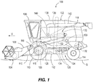
- FIG. 1 illustrates an agricultural vehicle 100 including a combine harvester 102 and an agricultural harvesting head 104, or "header", supported on the front of the vehicle 100.
- the combine harvester 102 includes an operator cabin 106 that contains controls for piloting and operating the combine harvester.
- a feederhouse 108 is pivotally coupled to the front of the combine harvester 102.
- One or more actuators 110 are coupled to and between the feeder house 108 and a chassis 112 of the combine harvester 102 to support the forward end of the feederhouse 108 and the agricultural harvesting head 104 above the ground.
- the chassis 112 is supported on wheels 114 that are driven by hydraulic motors 115 for travel over the ground level G1.
- the actuators 110 are double-acting hydraulic cylinders capable of moving from an extended position to a retracted position.
- the actuators 110 When the actuators 110 are extended, the forward end of the feederhouse 108 and the agricultural harvesting head 104 are raised upward, pivoting clockwise (in FIG. 1 ) about a pivot joint 116 that couples the feederhouse 108 to the chassis 112.
- the actuators 110 When the actuators 110 are retracted, the forward end of the feederhouse 108 and the agricultural harvesting head 104 are lowered, pivoting counterclockwise (in FIG. 1 ) about the pivot joint 116.
- the actuators 110 can be electric or pneumatic devices such as linear or rotary motors.
- the combine harvester 102 receives crop cut by the agricultural harvesting head 104 and conveys it into a threshing system 118.
- the threshing system 118 includes a rotor 120 that rotates against a concave 122 to separate grain from at least a portion of the "material other than grain” (MOG).
- MOG material other than grain
- the grain falls downward into a cleaning system 124.
- the cleaning system 124 includes at least one sieve or chaffer 126. Because the grain in the cleaning system can include some light MOG, the cleaning system 124 also includes a fan 128 that blows air through the sieve or chaffer 126. This airflow levitates light MOG and carries it rearward where it is deposited on the ground.
- a re-thresher 130 is provided at the rear of the threshing system 118 to receive the MOG separated from the grain. Grain remaining within the MOG is further separated from the MOG in the re-thresher 130 and drops into the cleaning system 124. The MOG leaves the threshing system 118 and is conveyed backward into a chopper 132, which throws the MOG onto the ground behind the vehicle 100.
- the grain that is cleaned in the cleaning system 124 is carried to an auger 134 that carries the clean grain to one side of the combine harvester 102.
- An elevator 136 receives the clean grain from the auger 134 and lifts the clean grain upward depositing it into a grain tank 138.
- an unloading vehicle such as a grain truck or grain cart will travel alongside the vehicle 100 and an auger 140 in the grain tank will unload the grain tank 138 through an elongate outlet 142.
- the elongate outlet 142 is pivoted outward from the vehicle 100 to extend over the grain truck or grain cart which receives the clean grain and carries it away for storage.
- the harvesting head 104 is supported on an end of the feederhouse 108 and extends transversely to direction of travel V and to a central axis 143 of the harvester vehicle 102.
- the harvesting head 104 can also have a center axis that is aligned with the central axis 143 of the harvester vehicle 102.
- the harvesting head 104 is wider than the chassis 112.
- the harvesting head 104 includes a forward edge 144, a rear edge 146, and a cutterbar 148 coupled to the forward edge 144.
- the cutterbar 148 extends substantially along the width of the harvesting head 104 and cuts or separates crop plants (not shown) from the ground G as the harvester vehicle 102 moves along the ground G.
- the cutterbar 148 may alternately be referred to as a cutting bar or reciprocating knife.
- the cutterbar 148 is flexible throughout (i.e., across the width of the harvesting head 104).
- the harvesting head 104 supports a first or right side conveyor 150, a second or left side conveyor 152, and an intermediate or center conveyor 154 positioned between the right side conveyor 150 and the left side conveyor 152.
- the center conveyor 154 is aligned with the chassis 112 centerline and, and each of the conveyors 150, 152, 154 are formed as endless belt conveyors.
- Each of the right side conveyor 150 and left side conveyor 152 comprises an endless belt that is supported on an inner roller adjacent to the center conveyor 154 and an outer roller adjacent to the respective distal ends of a main frame 204. As the cutting bar 148 severs crops from the ground G, the cut material falls onto the conveyors 150, 152, 154.
- the right side conveyor 150 moves cut material in a first direction 156 toward the center conveyor 154
- the left side conveyor 152 moves cut material in a second direction 158 toward the center conveyor 154
- the center conveyor 154 moves the cut material in a third direction 160 past a feed drum 162 and toward the feederhouse 108.
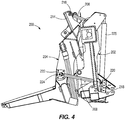
- FIGS. 3 and 4 show an exemplary embodiment of a header frame section 200 having first and second frame portions, for example an attachment frame 202 and a main frame 204.
- the attachment frame 202 connects to the feederhouse 108, and the main frame 204 supports the other components of the harvesting head 104, for example the cutterbar 148 and conveyors 150, 152, 154 shown in FIG. 2 .
- the main frame 204 is pivotally connected to the attachment frame 202 by a pair of upper control arms 206 and a pair of lower control arms 208.
- the upper control arms 206 are pivotally connected to a first bracket 210 on the attachment frame 202 at a first connection point 212 and pivotally connected to a second bracket 214 on the main frame 204 at a second connection point 216.
- the lower control arms 208 are pivotally connected to a third bracket 218 on the attachment frame 202 at a third connection point 220 and pivotally connected a fourth bracket 222 on the main frame 204 at a fourth connection point 224.
- the upper and lower control arms 206, 208 allow for height adjustment of the main frame 204 as it traverses uneven ground.
- one or more resilient float elements e.g., springs or hydraulic cylinders
- one or more resilient float elements are provided and arranged to exert a lifting force on the main frame 204.
- the main frame 204 of the harvesting head 104 is supported by the resilient float elements 225 for movement relative to the feederhouse 108 and the attachment frame 202 secured thereto.
- the main frame 204 of the harvesting head 104 may float passively relative to the feederhouse 108 and the attachment frame 202 by the resilient float elements 225, without being actively controlled.
- the main frame 204 is movably supported by the attachment frame 202, the main frame 204 has a limited range of travel.
- a nominal position of the main frame 204 and of the resilient float element(s) 225 is defined as an intermediate position within the range of travel, from which position the main frame 204 has the capability to travel in an upward direction and an opposite downward direction with respect to the attachment frame 202.
- the harvesting head 104 is configured to assume the nominal position on flat, level ground (i.e., when there is no need for following upward or downward ground irregularities).
- the actuators 110 are operable to vary the position of the feederhouse 108 and thus the position of the main frame 204 with respect to the attachment frame 202 by inducing more or less ground force
- the nominal position of the feederhouse 108 and the actuators 110 is also taken as the position or setting that corresponds to or brings about the nominal position of the main frame 204.
- the nominal position is defined as the main frame 204 being at the center of the range of travel with respect to the attachment frame 202, and the feederhouse position corresponding thereto, such that equal amounts of upward and downward travel from the nominal position are available.
- control arms 206, 208 extend along an axial direction that is non-parallel to the chassis axis 143.
- the upper control arms 206 are angled so that they diverge from the chassis axis 143 in the direction of travel V, with the first connection point 212 positioned closer to the chassis axis 143 than the second connection point 216.
- the lower control arms 208 are angled so that they converge toward the chassis axis 143 in the direction of travel V, with the third connection point 220 positioned further from the chassis axis 143 than the fourth connection point 224.
- the control arms 206, 208 can extend along an axis in a common plane which may or may not be parallel to the plane of the chassis axis 143.
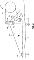
- FIGS. 5 and 6 show a simplified, two-dimensional representation of the attachment frame 202, the main frame 204, the upper control arms 206, the lower control arms 208 and the first through fourth connection points 212, 216, 220, 224 that define a roll center 226 for the attachment frame.
- FIG. 5 shows a first roll center 226 positioned at ground level G and
- FIG. 6 shows a second roll center 226 positioned below ground level G.
- the attachment frame 202, the main frame 204, the upper control arms 206, and the lower control arms 208 form a four-bar linkage with the intersection of the control arms 206, 208 defining the roll center 226.
- the roll center 226 is defined at the intersection between an upper control arm axis AI and a lower control arm axis A2.
- the control arms 206, 208 can extend non-parallel to the chassis axis 143 and in different planes. Accordingly, the roll center 226 is determined by a planar or two-dimensional representation of the upper and lower control arm axes AI, A2.
- the upper control arm axis AI is defined by the axis that extends through the first and second connection points 212, 216 viewed in a single plane.
- the lower control arm axis A2 is defined by the axis that extend through the third and fourth connection points 220, 224 viewed in a single plane.
- ground level position is not typically flat (as shown in FIG. 1 )
- the term ground level can mean ground level in the ordinary use of the term and also as a plane defined by the lower points of the front and back wheels 114, or other ground engaging members such as treads.
- both roll centers 126 are positioned below the harvester 102 and also between the wheels 114.
- the height of the ground can vary. Abrupt changes in height can cause engagement of the harvesting head 104 with the ground. Striking the ground creates a draft force that can increase the downward load on the main frame 204 and dislodges the proper position of the cutterbar 148, causing it to dig into the ground instead of cutting material just about ground level. When this happens repeatedly, the cutterbar 148 can become clogged with debris, and an operator will have to stop the operation of the agricultural vehicle 100 to clear the debris. By positioning the roll center at or below ground level, the draft forces acting on the harvester head 104 will act to lift the cutterbar 148, helping it to ride up and over crop material more easily, rather than pushing material in front of the cutterbar 148.
- movement or articulation within the main frame 204 may be enabled by a main frame 204 provided in sections such as a center section 204C, a left section or "wing” 204L movably (e.g., pivotally) coupled to the center section 204C, and a right section or “wing” 204R movably (e.g., pivotally) coupled to the center section 204C.
- a main frame 204 provided in sections such as a center section 204C, a left section or "wing” 204L movably (e.g., pivotally) coupled to the center section 204C, and a right section or “wing” 204R movably (e.g., pivotally) coupled to the center section 204C.
- Fore-and-aft extending pivot axes may be defined between the center section 204C and each of the left and right sections 204L, 204R.
- Each of the pivot axes can be defined by a simple hinge pin or by multiple links that define a point
- the left and right sections 204L, 204R may be independently supported with respect to the center section 204C with one or more resilient float elements (e.g., springs or hydraulic cylinders).
- the floatation system provided for the left and right sections 204L, 204R by the resilient float elements is a passive floatation system that is not actively controlled.
- each of a plurality of pivoting arms 326 (or “float arms”) is pivotally coupled to the main frame 204 at the rear ends to pivot about a corresponding horizontal and laterally extending pivot axis 328.
- the pivoting arms 326 are spaced apart across the width of the agricultural harvesting head 104 to provide distributed support to the cutterbar 148.
- the cutterbar 148 is fixed to and supported on the front ends of the pivoting arms 326.
- the cutterbar 148 is flexible along its length in a generally vertical direction such that it can flex and follow the contours of the ground (e.g., even assuming multiple arcs within either half thereof) as the ground rises and falls underneath the agricultural harvesting head 104 during forward travel.
- the pivoting arms 326 on which the cutterbar 148 is supported accommodate this up-and-down flexing of the reciprocating knife and hold the cutterbar 148 in position at the forward margin of the agricultural harvesting head 104.
- Each of the pivoting arms 326 has a skid 330 fixed to its front end adjacent to the cutterbar 148. As the agricultural harvester travels over the field, this skid 330 can lightly drag along the ground. As the ground presses up against the skid 330 the force provided by the ground lifts the forward end of the pivoting arms, causing them to pivot upward about their pivot points.
- FIG. 8 is a side view of a single pivoting arm 326.
- This pivoting arm is the same as all the other pivoting arms 326 that are supported on the main frame 204.
- a multi-bar linkage 332 couples the pivoting arm 326 to the main frame 204.
- This multi-bar linkage 332 includes a first link 334 extending between the pivoting arm 326 and the main frame 204.
- the first link 334 is pivotally coupled to the pivoting arm 326 at a first pivot joint 336 and is pivotally coupled to the main frame 204 at a second pivot joint 338.
- the multi-bar linkage 332 includes a second link 340 extending between the pivoting arm 326 and the main frame 204.
- the second link 340 is pivotally coupled to the pivoting arm 326 at a first pivot joint 342, and is pivotally coupled to the main frame 204 to second pivot joint 344.
- the first link 334, the second link 340, the pivoting arm 326 and the main frame 204 function together to define a four bar linkage. Due to the geometry of the four bar linkage, the pivoting arm 326 pivots with respect to the main frame 204 about a pivot point 346 that is disposed below the pivoting arm 326, below the cutterbar 148, below the skid 330, and below the surface of the ground G.
- the pivot point 346 is lower than pivot points are in the prior art. Therefore, if the cutterbar 148 or the skid 330 at the forward end of the pivoting arm 326 digs into the ground or runs into an object lying on the ground, the horizontal force applied to the cutterbar or skid by these obstacles will cause the pivoting arm 326 to lift upwards, away from the obstacle, as the pivoting arm 326 is forced backwards. This rearward and upward movement of the pivoting arm 326 will therefore tend to lift the front end of the arm 326 out of the ground and thus reduce the horizontal force. In short, the cutterbar 148 and skid 330 are lifted upward away from contact, rather than force downward into deeper contact us they would be if they pivoted about a pivot point located above the skid shoe and the cutterbar as shown in the prior art.
- pivot joint arrangements that similarly permit a pivoting arm 326 to pivot about a pivot point below the pivot arm, the reciprocating knife, and/or the shoe when encountering an obstacle in the field.
- FIG. 9 for example, two rollers 500, 502 are fixed to the pivoting arm 326.
- the main frame 204 has as an elongate curved slot 504 that receives the two rollers 500, 502.
- the slot 504 is longer than the distance between the two rollers 500, 502 and has the same width as the diameter of the two rollers 500, 502. Therefore, the pivoting arm 326 is constrained to roll back and forth in the slot 504. Due to the curvature of the slot 504, the pivoting arm 326 effectively pivots about a pivot point 506. Pivot point 506 is located at the center of curvature of the elongate curved slot 504.
- Pivot point 506 (like pivot point 346 in the previous arrangement) causes the pivoting arm 326 to pivot with respect to the elongate frame 124 about pivot point 506. Pivot point 506 is disposed below the pivoting arm 326, below the cutterbar 148, below the skid 330, and below the surface of the ground G.
- FIGS. 10 and 11 illustrate another pivoting arm arrangement for the harvesting head 104, and this arrangement is provided with pivoting arms 626 supported by first and second links 634, 640 similar to those of FIG. 8 for defining a pivot point 646 with respect to the mainframe 204 that is disposed below the pivoting arm 626, below the cutterbar 148, below the skid 630, and below the surface of the ground G.
- a resilient float element 650 e.g., spring or hydraulic cylinder acts on the four-bar linkage (e.g., between the main frame 204 and the second link 640) to bias the pivoting arm 626 upward to counter the weight of the cutterbar 148.
- a maximum downward position of the pivoting arm 626 is defined for example by a spring constant or hydraulic pressure of the resilient float element 650.
- each pivoting arm 626 has a limit of upward travel or rotation (clockwise in FIG. 10 ) provided by a stop 602.
- All of the pivoting arms 626 throughout the harvesting head 104 may also have respective stops 602.
- the stops 602 are provided on the main frame 204.
- the stops 602 are configured at a common height throughout the harvesting head 104 so that all the pivoting arms 626 align with each other in side view and the cutterbar 148 is straight when all the stops 602 are engaged.
- each pivoting arm 626 is defined in a range exclusively below the stops 602.
- FIG. 11 illustrates the pivoting arm 626 pivoted down away from the stop 602, which occurs as a result of the reduction of ground support from the nominal condition.
- the pivoting arms 626 are engaged with the stops 602.
- force from the ground G must be exerted on the pivoting arms 626, despite the resilient float elements 650 providing an upward bias. Only when the harvesting head 104 encounters a localized downward irregularity (i.e., a dip or depression) in the ground G will the pivoting arms 626 pivot down as shown in FIG. 11 . Downward pivoting of the pivoting arms 626 is generated passively by the weight of the cutterbar 148 against the bias of the resilient float elements 650.
- the pivoting arms 626 need not pivot down to follow the ground G if the ground irregularity is strictly on a macro level that is capable of being followed by articulation of the floatation system between the attachment frame 202 and the main frame 204 and/or the floatation system between sections 204C, 204L, 204R or "wings" of the main frame, if so equipped. This operational configuration is described in further detail with reference to FIGS. 12 and 13 .
- the cutterbar 148 will fall to its lower limit of travel with respect to the main frame 204, and the main frame 204 will fall to its lower limit of travel with respect to the attachment frame 202.
- the pivoting arms 626 e.g., at the skids 330
- the main frame 204 remains at its lower limit of travel.
- the pivoting arms 626 Once the pivoting arms 626 reach the stops 602, ground force is transmitted through the pivoting arms 626 and the stops 602 to the main frame 204, and with increasing ground force, the main frame 204 begins to settle toward the nominal position.
- the pivoting arms 626 are configured for one-way operation in the downward direction from the main frame 204 as the harvesting head 104 traverses the ground G.
- FIG. 12 shows such an example of the one-way downward operation when only a portion of the head 104 encounters a downward irregularity 1002 in the ground G.
- the pivoting arms 626 allow the cutterbar 148 to fall by its own weight with respect to the main frame 204.
- the pivoting arms 626 have the availability of their full range of travel since the nominal position is in engagement with the stops 602.
- a portion of the harvesting head 104 may encounter an upward irregularity 1004 as in FIG. 13 .
- ground force from the irregularity 1004 in the ground G is transmitted directly to the main frame 204 without requiring any take-up in the pivoting arms 626.
- upward articulation is provided by the resilient floatation system between the main frame 204 and the attachment frame 202 and/or the resilient floatation system between the sections 204C, 204L, 204R of the main frame 204 (both are shown in the example of FIG. 13 ).
- the main frame 204, or a section thereof rises to the highest point of the upward irregularity 1004, adjacent portions of the flexible cutterbar 148 descend freely from the main frame 204. The full range of downward travel is available for each of the pivoting arms 626.
- portions of the cutterbar 148 can follow level or even depressed portions of the ground G while the main frame 204 is upwardly articulated by the upward irregularity 1004.
- pivoting arms 626 of FIGS. 10 and 11 in which drawings the stops 602 are also illustrated it is noted that the configurations and operations described herein with respect to the pivoting arms 626 may be equally applied to the other disclosed embodiments of pivoting arms 326 in FIGS. 7-9 .
- the pivoting arms can be pivoted fully upward to an upper limit when the harvesting head 104 is set in the nominal position, and certain benefits are obtained by such a configuration, it is also noted that in other constructions the pivoting arms have 10 percent or less of total available travel as upward travel and at least 90 percent of total available travel as downward travel when the harvesting head 104 is set in the nominal position.
- Operation of the agricultural vehicle 100 including the combine harvester 102 and the harvesting head 104 as disclosed above can obviate the need to actively manage a sensor-based ground-following routine with the combine harvester 102 whereby the positions of the various pivoting arms are monitored and used as a controller input for raising and lowering the main frame 204 (e.g., by raising and lowering the feederhouse 108 with the actuators 110).
- the above disclosed structure and method of operation need not actively manage the position of the harvesting head 104 or portions thereof.
- the ground-following feature of the harvesting head 104 can be entirely passive (and thus, mechanical rather than computer- controlled) within the travel range of the main frame 204 with respect to the attachment frame 202.
- the agricultural vehicle 100 may be equipped with one or more limit sensors that are configured to detect the main frame 204 reaching or approaching its maximum limit of travel (up or down) with respect to the attachment frame 202. Such detection may be configured (e.g., controller-programmed) to bring about a repositioning of the feederhouse 108 under certain conditions (e.g., time duration exceeding a threshold limit).
- the terms “front,” “rear,” “upper,” “lower,” “upwardly,” “downwardly,” and other orientational descriptors are intended to facilitate the description of the exemplary embodiments of the present disclosure, and are not intended to limit the structure of the exemplary embodiments of the present disclosure to any particular position or orientation.
- Terms of degree, such as “substantially” or “approximately” are understood by those of ordinary skill to refer to reasonable ranges outside of the given value, for example, general tolerances associated with manufacturing, assembly, and use of the described embodiments.
Landscapes
- Life Sciences & Earth Sciences (AREA)
- Environmental Sciences (AREA)
- Harvester Elements (AREA)
- Agricultural Machines (AREA)
Abstract
Description
- The disclosure relates to headers for combine harvesters, and more particularly headers having flexible cutter bars for ground following during crop cutting.
- The disclosure provides, in one aspect, a harvesting head for a combine. The harvesting head includes an attachment frame provided at an aft end of the head for attachment with a combine feederhouse. A main frame of the harvesting head is movably connected to the attachment frame to define a roll center therebetween, and the main frame has a range of travel about the roll center with respect to the attachment frame. At least one resilient float element is provided between the attachment frame and the main frame and operable to exert a lifting force on the main frame. A flexible cutterbar is positioned at a forward edge of the main frame and operable to reciprocate for cutting crop material from the ground. The cutterbar is supported on the main frame by a plurality of pivoting arms distributed across a width of the head. With the main frame in a nominal intermediate position within the range of travel, the plurality of pivoting arms have 10 percent or less of total available travel as upward travel and at least 90 percent of total available travel as downward travel when the harvesting head is set in the nominal position.
- The disclosure provides, in another aspect, a harvesting head for a combine. The harvesting head includes an attachment frame provided at an aft end of the head for attachment with a combine feederhouse. A main frame of the harvesting head is movably connected to the attachment frame to define a roll center therebetween, and the main frame has a range of travel about the roll center with respect to the attachment frame. At least one resilient float element is provided between the attachment frame and the main frame and operable to exert a lifting force on the main frame. A cutterbar is positioned at a forward edge of the main frame and operable to reciprocate for cutting crop material from the ground. The cutterbar extends across a width of the head and is flexible throughout. The cutterbar is supported on the main frame by a plurality of pivoting arms distributed across the width of the head. With the main frame centered in the range of travel, each of the plurality of pivoting arms is pivoted maximally upward into contact with a corresponding top stop on the main frame so that the cutterbar is in an uppermost position that is configured to follow ground irregularities exclusively in a downward travel direction from the main frame.
- The disclosure provides, in yet another aspect, a method of operating a combine with a harvesting head. The harvesting head is provided having a main frame movably supported by a first resilient float system on an attachment frame, and having a flexible cutterbar supported by a second resilient float system with a plurality of pivoting arms on the main frame. The attachment frame is secured to a combine feederhouse. A nominal position of the feederhouse that rests the plurality of pivoting arms on the ground and transmits ground force through the plurality of pivoting arms to the main frame to deflect the first resilient float system and move the main frame upward relative to the attachment frame is set so that the main frame is in the center of a range of available travel with respect to the attachment frame. The combine is operated over irregular ground, and during operation, ground force is transmitted from an upward ground irregularity through a first one of the plurality of pivoting arms directly to the main frame without requiring any initial take-up of the first one of the plurality of pivoting arms with respect to the main frame. In response to upward articulation of the main frame by the transmitted ground force, a second one of the plurality of pivoting arms stays in contact with the ground by falling from its uppermost position on the main frame by an amount up to its full range of travel in order to follow the ground adjacent the upward ground irregularity.
- Further aspects of the disclosure can include combinations of any or all of the features set forth in the following paragraphs.
- A harvesting head for a combine includes an attachment frame provided at an aft end of the head for attachment with a combine feederhouse; a main frame movably connected to the attachment frame to define a roll center therebetween, wherein the main frame has a range of travel about the roll center with respect to the attachment frame; at least one resilient float element provided between the attachment frame and the main frame and operable to exert a lifting force on the main frame; and a flexible cutterbar positioned at a forward edge of the main frame and operable to reciprocate for cutting crop material from the ground. The cutterbar is supported on the main frame by a plurality of pivoting arms distributed across a width of the head. With the main frame in a nominal intermediate position within the range of travel, the plurality of pivoting arms have 10 percent or less of total available travel as upward travel and at least 90 percent of total available travel as downward travel when the harvesting head is set in the nominal position.
- With the main frame centered in the range of travel, each of the plurality of pivoting arms is pivoted maximally upward into contact with a corresponding top stop on the main frame so that the cutterbar is in an uppermost position that is configured to follow ground irregularities exclusively in a downward travel direction from the main frame.
- The pivoting arms are biased upwardly to partially counterbalance a weight of the cutterbar supported thereby.
- Resilient float elements upwardly biasing the plurality of pivoting arms provide a maximum lifting force defining a lower limit position of the plurality of pivoting arms relative to the main frame, and force from the ground pivots the plurality of pivoting arms upward from their lower limit positions.
- The plurality of pivoting arms pivot about a point at or below ground level when the main frame is in the nominal intermediate position.
- The at least one resilient float element provided between the attachment frame and the main frame is passive in its operation and not actively controlled.
- The pivoting arms are supported by a passive resilient float system including at least one resilient float element.
- The resilient float system comprises one resilient float element for each of the plurality of pivoting arms.
- The main frame includes a plurality of top stops defining respective upper limit positions for the plurality of pivoting arms.
- The main frame is provided in sections including a center section and respective left and right sections extending in opposite lateral directions from the center section, wherein the left and right sections are individually pivotably supported relative to the center section.
- The left and right sections are supported by a passive resilient floatation system with respect to the center section.
- The cutterbar of the harvesting head extends across the width of the head and is flexible throughout.
- An agricultural work vehicle comprising a combine and the harvesting head according to any one of the preceding claims.
- A method of operating a combine with a harvesting head includes providing a harvesting head having a main frame movably supported by a first resilient float system on an attachment frame, and having a flexible cutterbar supported by a second resilient float system with a plurality of pivoting arms on the main frame; securing the attachment frame to a combine feederhouse; setting a nominal position of the feederhouse that rests the plurality of pivoting arms on the ground and transmits ground force through the plurality of pivoting arms to the main frame to deflect the first resilient float system and move the main frame upward relative to the attachment frame so that the main frame is in the center of a range of available travel with respect to the attachment frame; operating the combine over irregular ground; during operation of the combine, transmitting ground force from an upward ground irregularity through a first one of the plurality of pivoting arms to the main frame after an initial take-up of the first one of the plurality of pivoting arms with respect to the main frame, the initial take-up being zero percent to 10 percent of total available travel; and in response to upward articulation of the main frame by the transmitted ground force, allowing a second one of the plurality of pivoting arms to stay in contact with the ground adjacent the upward ground irregularity.
- The ground force is transmitted from the upward ground irregularity through the first one of the plurality of pivoting arms directly to the main frame with zero initial take-up of the first one of the plurality of pivoting arms with respect to the main frame.
- Further aspects are set forth in the detailed description and accompanying drawings.
-
-
FIG. 1 is a side view of an agricultural vehicle. -
FIG. 2 is a top view of the agricultural vehicle ofFIG. 1 . -
FIG. 3 is a front perspective view of a header frame section. -
FIG. 4 is a side view of the header frame section ofFIG. 3 . -
FIG. 5 is a schematic view depicting a first exemplary roll center of the frame section ofFIG. 3 positioned at ground level. -
FIG. 6 is a schematic view depicting a second exemplary roll center of the frame section ofFIG. 3 positioned below ground level. -
FIG. 7 is a plan view of the agricultural vehicle ofFIG. 1 , having belts removed to illustrate a plurality of cutterbar-supporting pivoting arms. -
FIG. 8 is a cross-sectional view of the agricultural harvesting head ofFIG. 7 taken at section line 8-8 and showing a first float arm arrangement in accordance with the present invention. -
FIG. 9 is a cross-sectional view of the agricultural harvesting head ofFIG. 7 showing a second float arm arrangement in accordance with the present invention. -
FIG. 10 is a cross-sectional view of the agricultural harvesting head ofFIG. 7 showing a third float arm arrangement in accordance with the present invention. -
FIG. 11 is a cross-sectional view of the third float arm arrangement ofFIG. 10 showing a downwardly pivoted position. -
FIG. 12 is a front view of the harvesting head encountering a first ground irregularity, accommodated by the float arm arrangement alone. -
FIG. 13 is a front view of the harvesting head encountering a second ground irregularity, accommodated in part by the float arm arrangement. - Before any embodiments are explained in detail, it is to be understood that the disclosure is not limited in its application to the details of construction and the arrangement of components set forth in the following description or illustrated in the accompanying drawings. The terms "side-to-side," "sideways," "laterally," or "lateral" refer to a direction that is horizontal and generally parallel to the longitudinal extent of the agricultural harvesting head itself. This direction is perpendicular to a direction of travel "V" of the machine as it travels through the field harvesting crops. The terms "in front of," "front," "forward," "fore," and the like refer to the direction of travel "V." The terms "back," "rear," "behind," "to the rear of," and the like refer to a direction opposite to the direction of travel "V."
-
FIG. 1 illustrates anagricultural vehicle 100 including acombine harvester 102 and anagricultural harvesting head 104, or "header", supported on the front of thevehicle 100. Thecombine harvester 102 includes anoperator cabin 106 that contains controls for piloting and operating the combine harvester. Afeederhouse 108 is pivotally coupled to the front of thecombine harvester 102. One ormore actuators 110 are coupled to and between thefeeder house 108 and achassis 112 of thecombine harvester 102 to support the forward end of thefeederhouse 108 and theagricultural harvesting head 104 above the ground. Thechassis 112 is supported onwheels 114 that are driven byhydraulic motors 115 for travel over the ground level G1. - The
actuators 110 are double-acting hydraulic cylinders capable of moving from an extended position to a retracted position. When theactuators 110 are extended, the forward end of thefeederhouse 108 and theagricultural harvesting head 104 are raised upward, pivoting clockwise (inFIG. 1 ) about a pivot joint 116 that couples thefeederhouse 108 to thechassis 112. When theactuators 110 are retracted, the forward end of thefeederhouse 108 and theagricultural harvesting head 104 are lowered, pivoting counterclockwise (inFIG. 1 ) about thepivot joint 116. - Thus, by extending and retracting the
actuators 110, the height of thefeederhouse 108 and theagricultural harvesting head 104 can be varied. Furthermore, changing the hydraulic fluid pressure in theactuators 110 will change the amount of downforce exerted by theagricultural harvesting head 104 against the ground. As the hydraulic fluid pressure in theactuators 110 increases, the downforce applied by theagricultural harvesting head 104 to the ground will decrease. As the hydraulic fluid pressure in theactuators 110 decreases, the downforce due to the weight of theagricultural harvesting head 104 will increase. In an alternative arrangement, theactuators 110 can be electric or pneumatic devices such as linear or rotary motors. - The
combine harvester 102 receives crop cut by theagricultural harvesting head 104 and conveys it into a threshingsystem 118. The threshingsystem 118 includes arotor 120 that rotates against a concave 122 to separate grain from at least a portion of the "material other than grain" (MOG). The grain falls downward into acleaning system 124. Thecleaning system 124 includes at least one sieve orchaffer 126. Because the grain in the cleaning system can include some light MOG, thecleaning system 124 also includes afan 128 that blows air through the sieve orchaffer 126. This airflow levitates light MOG and carries it rearward where it is deposited on the ground. - A re-thresher 130 is provided at the rear of the threshing
system 118 to receive the MOG separated from the grain. Grain remaining within the MOG is further separated from the MOG in the re-thresher 130 and drops into thecleaning system 124. The MOG leaves the threshingsystem 118 and is conveyed backward into achopper 132, which throws the MOG onto the ground behind thevehicle 100. - The grain that is cleaned in the
cleaning system 124 is carried to anauger 134 that carries the clean grain to one side of thecombine harvester 102. Anelevator 136 receives the clean grain from theauger 134 and lifts the clean grain upward depositing it into agrain tank 138. - Periodically, an unloading vehicle such as a grain truck or grain cart will travel alongside the
vehicle 100 and anauger 140 in the grain tank will unload thegrain tank 138 through anelongate outlet 142. Theelongate outlet 142 is pivoted outward from thevehicle 100 to extend over the grain truck or grain cart which receives the clean grain and carries it away for storage. - As shown in
FIG. 2 , theharvesting head 104 is supported on an end of thefeederhouse 108 and extends transversely to direction of travel V and to acentral axis 143 of theharvester vehicle 102. Theharvesting head 104 can also have a center axis that is aligned with thecentral axis 143 of theharvester vehicle 102. In the illustrated embodiment, theharvesting head 104 is wider than thechassis 112. Theharvesting head 104 includes aforward edge 144, arear edge 146, and acutterbar 148 coupled to theforward edge 144. Thecutterbar 148 extends substantially along the width of theharvesting head 104 and cuts or separates crop plants (not shown) from the ground G as theharvester vehicle 102 moves along the ground G. Thecutterbar 148 may alternately be referred to as a cutting bar or reciprocating knife. Thecutterbar 148 is flexible throughout (i.e., across the width of the harvesting head 104). - The
harvesting head 104 supports a first orright side conveyor 150, a second orleft side conveyor 152, and an intermediate orcenter conveyor 154 positioned between theright side conveyor 150 and theleft side conveyor 152. In the illustrated embodiment, thecenter conveyor 154 is aligned with thechassis 112 centerline and, and each of theconveyors right side conveyor 150 andleft side conveyor 152 comprises an endless belt that is supported on an inner roller adjacent to thecenter conveyor 154 and an outer roller adjacent to the respective distal ends of amain frame 204. As the cuttingbar 148 severs crops from the ground G, the cut material falls onto theconveyors right side conveyor 150 moves cut material in afirst direction 156 toward thecenter conveyor 154, and theleft side conveyor 152 moves cut material in asecond direction 158 toward thecenter conveyor 154. Thecenter conveyor 154 moves the cut material in athird direction 160 past afeed drum 162 and toward thefeederhouse 108. -
FIGS. 3 and4 show an exemplary embodiment of aheader frame section 200 having first and second frame portions, for example anattachment frame 202 and amain frame 204. Theattachment frame 202 connects to thefeederhouse 108, and themain frame 204 supports the other components of theharvesting head 104, for example thecutterbar 148 andconveyors FIG. 2 . - The
main frame 204 is pivotally connected to theattachment frame 202 by a pair ofupper control arms 206 and a pair oflower control arms 208. Theupper control arms 206 are pivotally connected to afirst bracket 210 on theattachment frame 202 at afirst connection point 212 and pivotally connected to asecond bracket 214 on themain frame 204 at asecond connection point 216. Thelower control arms 208 are pivotally connected to athird bracket 218 on theattachment frame 202 at athird connection point 220 and pivotally connected afourth bracket 222 on themain frame 204 at afourth connection point 224. The upper andlower control arms main frame 204 as it traverses uneven ground. In particular, one or more resilient float elements (e.g., springs or hydraulic cylinders) 225 are provided and arranged to exert a lifting force on themain frame 204. Although movement of thefeederhouse 108 by theactuators 110 can raise or lower theharvesting head 104 as needed, themain frame 204 of theharvesting head 104 is supported by theresilient float elements 225 for movement relative to thefeederhouse 108 and theattachment frame 202 secured thereto. Themain frame 204 of theharvesting head 104 may float passively relative to thefeederhouse 108 and theattachment frame 202 by theresilient float elements 225, without being actively controlled. Although themain frame 204 is movably supported by theattachment frame 202, themain frame 204 has a limited range of travel. A nominal position of themain frame 204 and of the resilient float element(s) 225 is defined as an intermediate position within the range of travel, from which position themain frame 204 has the capability to travel in an upward direction and an opposite downward direction with respect to theattachment frame 202. Theharvesting head 104 is configured to assume the nominal position on flat, level ground (i.e., when there is no need for following upward or downward ground irregularities). Although theactuators 110 are operable to vary the position of thefeederhouse 108 and thus the position of themain frame 204 with respect to theattachment frame 202 by inducing more or less ground force, the nominal position of thefeederhouse 108 and theactuators 110 is also taken as the position or setting that corresponds to or brings about the nominal position of themain frame 204. In some constructions, the nominal position is defined as themain frame 204 being at the center of the range of travel with respect to theattachment frame 202, and the feederhouse position corresponding thereto, such that equal amounts of upward and downward travel from the nominal position are available. - In an exemplary embodiment the
control arms chassis axis 143. Theupper control arms 206 are angled so that they diverge from thechassis axis 143 in the direction of travel V, with thefirst connection point 212 positioned closer to thechassis axis 143 than thesecond connection point 216. Thelower control arms 208 are angled so that they converge toward thechassis axis 143 in the direction of travel V, with thethird connection point 220 positioned further from thechassis axis 143 than thefourth connection point 224. In other embodiments, thecontrol arms chassis axis 143. -
FIGS. 5 and6 show a simplified, two-dimensional representation of theattachment frame 202, themain frame 204, theupper control arms 206, thelower control arms 208 and the first through fourth connection points 212, 216, 220, 224 that define aroll center 226 for the attachment frame.FIG. 5 shows afirst roll center 226 positioned at ground level G andFIG. 6 shows asecond roll center 226 positioned below ground level G. In this schematic view theattachment frame 202, themain frame 204, theupper control arms 206, and thelower control arms 208 form a four-bar linkage with the intersection of thecontrol arms roll center 226. - In the illustrated embodiments, the
roll center 226 is defined at the intersection between an upper control arm axis AI and a lower control arm axis A2. As discussed above, thecontrol arms chassis axis 143 and in different planes.
Accordingly, theroll center 226 is determined by a planar or two-dimensional representation of the upper and lower control arm axes AI, A2. The upper control arm axis AI is defined by the axis that extends through the first and second connection points 212, 216 viewed in a single plane. The lower control arm axis A2 is defined by the axis that extend through the third and fourth connection points 220, 224 viewed in a single plane.FIG. 5 shows an embodiment in which the upper control arm axis AI and the lower control arm axis A2 intersect at ground level G, therefore creating aroll center 226 at ground level G.FIG. 6 shows an embodiment in which the upper control arm axis AI and the lower control arm axis A2 intersect below ground level G, therefore creating aroll center 226 below ground level G. Because the ground level position is not typically flat (as shown inFIG. 1 ), the term ground level can mean ground level in the ordinary use of the term and also as a plane defined by the lower points of the front andback wheels 114, or other ground engaging members such as treads. As shown inFIGS. 5 and6 , both roll centers 126 are positioned below theharvester 102 and also between thewheels 114. - As mentioned, when the
vehicle 100 is traveling, the height of the ground can vary. Abrupt changes in height can cause engagement of theharvesting head 104 with the ground.
Striking the ground creates a draft force that can increase the downward load on themain frame 204 and dislodges the proper position of thecutterbar 148, causing it to dig into the ground instead of cutting material just about ground level. When this happens repeatedly, thecutterbar 148 can become clogged with debris, and an operator will have to stop the operation of theagricultural vehicle 100 to clear the debris. By positioning the roll center at or below ground level, the draft forces acting on theharvester head 104 will act to lift thecutterbar 148, helping it to ride up and over crop material more easily, rather than pushing material in front of thecutterbar 148. - In addition to the movement afforded between the
main frame 204 and theattachment frame 202, movement or articulation within themain frame 204 may be enabled by amain frame 204 provided in sections such as acenter section 204C, a left section or "wing" 204L movably (e.g., pivotally) coupled to thecenter section 204C, and a right section or "wing" 204R movably (e.g., pivotally) coupled to thecenter section 204C. Fore-and-aft extending pivot axes may be defined between thecenter section 204C and each of the left andright sections right sections center section 204C with one or more resilient float elements (e.g., springs or hydraulic cylinders). In some constructions, the floatation system provided for the left andright sections - As shown in
FIGS. 7-9 , each of a plurality of pivoting arms 326 (or "float arms") is pivotally coupled to themain frame 204 at the rear ends to pivot about a corresponding horizontal and laterally extendingpivot axis 328. The pivotingarms 326 are spaced apart across the width of theagricultural harvesting head 104 to provide distributed support to thecutterbar 148. - The
cutterbar 148 is fixed to and supported on the front ends of the pivotingarms 326. Thecutterbar 148 is flexible along its length in a generally vertical direction such that it can flex and follow the contours of the ground (e.g., even assuming multiple arcs within either half thereof) as the ground rises and falls underneath theagricultural harvesting head 104 during forward travel. The pivotingarms 326 on which thecutterbar 148 is supported accommodate this up-and-down flexing of the reciprocating knife and hold thecutterbar 148 in position at the forward margin of theagricultural harvesting head 104. - Each of the pivoting
arms 326 has askid 330 fixed to its front end adjacent to thecutterbar 148. As the agricultural harvester travels over the field, thisskid 330 can lightly drag along the ground. As the ground presses up against theskid 330 the force provided by the ground lifts the forward end of the pivoting arms, causing them to pivot upward about their pivot points. -
FIG. 8 is a side view of asingle pivoting arm 326. This pivoting arm is the same as all the other pivotingarms 326 that are supported on themain frame 204. In the pivoting arm arrangement ofFIG. 8 , amulti-bar linkage 332 couples the pivotingarm 326 to the main frame
204. Thismulti-bar linkage 332 includes afirst link 334 extending between the pivotingarm 326 and themain frame 204. Thefirst link 334 is pivotally coupled to thepivoting arm 326 at a first pivot joint 336 and is pivotally coupled to themain frame 204 at asecond pivot joint 338. Themulti-bar linkage 332 includes asecond link 340 extending between the pivotingarm 326 and themain frame 204. Thesecond link 340 is pivotally coupled to thepivoting arm 326 at a first pivot joint 342, and is pivotally coupled to themain frame 204 tosecond pivot joint 344. - The
first link 334, thesecond link 340, the pivotingarm 326 and themain frame 204 function together to define a four bar linkage. Due to the geometry of the four bar linkage, the pivotingarm 326 pivots with respect to themain frame 204 about a pivot point 346 that is disposed below the pivotingarm 326, below thecutterbar 148, below theskid 330, and below the surface of the ground G. - The pivot point 346 is lower than pivot points are in the prior art. Therefore, if the
cutterbar 148 or theskid 330 at the forward end of the pivotingarm 326 digs into the ground or runs into an object lying on the ground, the horizontal force applied to the cutterbar or skid by these obstacles will cause thepivoting arm 326 to lift upwards, away from the obstacle, as the pivotingarm 326 is forced backwards. This rearward and upward movement of the pivotingarm 326 will therefore tend to lift the front end of thearm 326 out of the ground and thus reduce the horizontal force. In short, thecutterbar 148 and skid 330 are lifted upward away from contact, rather than force downward into deeper contact us they would be if they pivoted about a pivot point located above the skid shoe and the cutterbar as shown in the prior art. - In this manner, any damage to the
agricultural harvesting head 104 due to collisions with obstacles in the field is reduced. - There are other pivot joint arrangements that similarly permit a
pivoting arm 326 to pivot about a pivot point below the pivot arm, the reciprocating knife, and/or the shoe when encountering an obstacle in the field. - In
FIG. 9 , for example, tworollers pivoting arm 326. Themain frame 204 has as an elongatecurved slot 504 that receives the tworollers slot 504 is longer than the distance between the tworollers rollers arm 326 is constrained to roll back and forth in theslot 504. Due to the curvature of theslot 504, the pivotingarm 326 effectively pivots about apivot point 506.Pivot point 506 is located at the center of curvature of the elongatecurved slot 504. - Pivot point 506 (like pivot point 346 in the previous arrangement) causes the
pivoting arm 326 to pivot with respect to theelongate frame 124 aboutpivot point 506.Pivot point 506 is disposed below the pivotingarm 326, below thecutterbar 148, below theskid 330, and below the surface of the ground G. -
FIGS. 10 and 11 illustrate another pivoting arm arrangement for theharvesting head 104, and this arrangement is provided with pivotingarms 626 supported by first andsecond links FIG. 8 for defining a pivot point 646 with respect to themainframe 204 that is disposed below the pivotingarm 626, below thecutterbar 148, below the skid 630, and below the surface of the ground G. A resilient float element 650 (e.g., spring or hydraulic cylinder) acts on the four-bar linkage (e.g., between themain frame 204 and the second link 640) to bias the pivotingarm 626 upward to counter the weight of thecutterbar 148. In a completely passive arrangement, a maximum downward position of the pivotingarm 626 is defined for example by a spring constant or hydraulic pressure of theresilient float element 650. As shown inFIG. 10 , each pivotingarm 626 has a limit of upward travel or rotation (clockwise inFIG. 10 ) provided by astop 602. All of the pivotingarms 626 throughout theharvesting head 104 may also haverespective stops 602. Thestops 602 are provided on themain frame 204. Thestops 602 are configured at a common height throughout theharvesting head 104 so that all the pivotingarms 626 align with each other in side view and thecutterbar 148 is straight when all thestops 602 are engaged. Due to thestops 602, the range of travel of each pivotingarm 626 is defined in a range exclusively below thestops 602.FIG. 11 illustrates the pivotingarm 626 pivoted down away from thestop 602, which occurs as a result of the reduction of ground support from the nominal condition. - On level ground with the
harvesting head 104 set in its nominal position, the pivotingarms 626 are engaged with thestops 602. To engage the pivotingarms 626 with thestops 602, force from the ground G must be exerted on the pivotingarms 626, despite theresilient float elements 650 providing an upward bias. Only when theharvesting head 104 encounters a localized downward irregularity (i.e., a dip or depression) in the ground G will the pivotingarms 626 pivot down as shown inFIG. 11 . Downward pivoting of the pivotingarms 626 is generated passively by the weight of thecutterbar 148 against the bias of theresilient float elements 650.
The pivotingarms 626 need not pivot down to follow the ground G if the ground irregularity is strictly on a macro level that is capable of being followed by articulation of the floatation system between theattachment frame 202 and themain frame 204 and/or the floatation system betweensections FIGS. 12 and 13 . - If the
harvesting head 104 is lifted completely off the ground (e.g., by the upward movement of thefeederhouse 108 via the actuators 110), thecutterbar 148 will fall to its lower limit of travel with respect to themain frame 204, and themain frame 204 will fall to its lower limit of travel with respect to theattachment frame 202. When lowered to initiate ground contact and force from the ground G onto theharvesting head 104, the pivoting arms 626 (e.g., at the skids 330) contact first and begin to pivot upwardly toward thestops 602. Themain frame 204 remains at its lower limit of travel. Once the pivotingarms 626 reach thestops 602, ground force is transmitted through the pivotingarms 626 and thestops 602 to themain frame 204, and with increasing ground force, themain frame 204 begins to settle toward the nominal position.
Thus, when operating theharvesting head 104 over uneven ground from the nominal position, upward ground irregularities are immediately transmitted to themain frame 204 without requiring any take-up in the pivoting arms 626 (i.e., no pivoting movement prior engaging the stops 602). As such, the pivotingarms 626 are configured for one-way operation in the downward direction from themain frame 204 as theharvesting head 104 traverses the ground G.FIG. 12 shows such an example of the one-way downward operation when only a portion of thehead 104 encounters adownward irregularity 1002 in the ground G. With the localized reduction in ground force to the pivotingarms 626, the pivotingarms 626 allow thecutterbar 148 to fall by its own weight with respect to themain frame 204. The pivotingarms 626 have the availability of their full range of travel since the nominal position is in engagement with thestops 602. Conversely, a portion of theharvesting head 104 may encounter anupward irregularity 1004 as inFIG. 13 . When this occurs, ground force from theirregularity 1004 in the ground G is transmitted directly to themain frame 204 without requiring any take-up in the pivotingarms 626. As such, upward articulation is provided by the resilient floatation system between themain frame 204 and theattachment frame 202 and/or the resilient floatation system between thesections FIG. 13 ). As themain frame 204, or a section thereof, rises to the highest point of theupward irregularity 1004, adjacent portions of theflexible cutterbar 148 descend freely from themain frame 204. The full range of downward travel is available for each of the pivotingarms 626. Thus, depending on the particular ground surface, portions of thecutterbar 148 can follow level or even depressed portions of the ground G while themain frame 204 is upwardly articulated by theupward irregularity 1004. Although the description directly above is particularly directed toward the pivotingarms 626 ofFIGS. 10 and 11 in which drawings thestops 602 are also illustrated, it is noted that the configurations and operations described herein with respect to the pivotingarms 626 may be equally applied to the other disclosed embodiments of pivotingarms 326 inFIGS. 7-9 . Furthermore, while it has been described that the pivoting arms can be pivoted fully upward to an upper limit when theharvesting head 104 is set in the nominal position, and certain benefits are obtained by such a configuration, it is also noted that in other constructions the pivoting arms have 10 percent or less of total available travel as upward travel and at least 90 percent of total available travel as downward travel when theharvesting head 104 is set in the nominal position. - Operation of the
agricultural vehicle 100 including thecombine harvester 102 and theharvesting head 104 as disclosed above can obviate the need to actively manage a sensor-based ground-following routine with thecombine harvester 102 whereby the positions of the various pivoting arms are monitored and used as a controller input for raising and lowering the main frame 204 (e.g., by raising and lowering thefeederhouse 108 with the actuators 110). To the contrary, the above disclosed structure and method of operation need not actively manage the position of theharvesting head 104 or portions thereof. Thus, the ground-following feature of theharvesting head 104 can be entirely passive (and thus, mechanical rather than computer- controlled) within the travel range of themain frame 204 with respect to theattachment frame 202. Although designed to be fully capable of following irregular ground without sensor feedback of active positioning, theagricultural vehicle 100 may be equipped with one or more limit sensors that are configured to detect themain frame 204 reaching or approaching its maximum limit of travel (up or down) with respect to theattachment frame 202. Such detection may be configured (e.g., controller-programmed) to bring about a repositioning of thefeederhouse 108 under certain conditions (e.g., time duration exceeding a threshold limit). - The foregoing detailed description of the certain exemplary embodiments has been provided for the purpose of explaining the general principles and practical application, thereby enabling others skilled in the art to understand the disclosure for various embodiments and with various modifications as are suited to the particular use contemplated. This description is not necessarily intended to be exhaustive or to limit the disclosure to the exemplary embodiments disclosed. Any of the embodiments and/or elements disclosed herein may be combined with one another to form various additional embodiments not specifically disclosed. Accordingly, additional embodiments are possible and are intended to be encompassed within this specification and the scope of the appended claims. The specification describes specific examples to accomplish a more general goal that may be accomplished in another way.
- As used in this application, the terms "front," "rear," "upper," "lower," "upwardly," "downwardly," and other orientational descriptors are intended to facilitate the description of the exemplary embodiments of the present disclosure, and are not intended to limit the structure of the exemplary embodiments of the present disclosure to any particular position or orientation.
Terms of degree, such as "substantially" or "approximately" are understood by those of ordinary skill to refer to reasonable ranges outside of the given value, for example, general tolerances associated with manufacturing, assembly, and use of the described embodiments. - Various features and advantages are set forth in the following claims.
Claims (15)
- A harvesting head for a combine, the harvesting head comprising:an attachment frame provided at an aft end of the head for attachment with a combine feederhouse;a main frame movably connected to the attachment frame to define a roll center therebetween, wherein the main frame has a range of travel about the roll center with respect to the attachment frame;at least one resilient float element provided between the attachment frame and the main frame and operable to exert a lifting force on the main frame;a flexible cutterbar positioned at a forward edge of the main frame and operable to reciprocate for cutting crop material from the ground, wherein the cutterbar is supported on the main frame by a plurality of pivoting arms distributed across a width of the head;wherein, with the main frame in a nominal intermediate position within the range of travel, the plurality of pivoting arms have 10 percent or less of total available travel as upward travel and at least 90 percent of total available travel as downward travel when the harvesting head is set in the nominal position.
- The harvesting head of claim 1, wherein the plurality of pivoting arms are biased upwardly to partially counterbalance a weight of the cutterbar supported thereby.
- The harvesting head of claim 2, wherein resilient float elements upwardly biasing the plurality of pivoting arms provide a maximum lifting force defining a lower limit position of the plurality of pivoting arms relative to the main frame, and force from the ground pivots the plurality of pivoting arms upward from their lower limit positions.
- The harvesting head of claim 1, wherein the plurality of pivoting arms pivot about a point at or below ground level when the main frame is in the nominal intermediate position.
- The harvesting head of claim 1, wherein the at least one resilient float element provided between the attachment frame and the main frame is passive in its operation and not actively controlled.
- The harvesting head of claim 5, wherein the plurality of pivoting arms are supported by a passive resilient float system including at least one resilient float element.
- The harvesting head of claim 6, wherein the resilient float system comprises one resilient float element for each of the plurality of pivoting arms.
- The harvesting head of claim 1, wherein the main frame includes a plurality of top stops defining respective upper limit positions for the plurality of pivoting arms.
- The harvesting head of claim 1, wherein the main frame is provided in sections including a center section and respective left and right sections extending in opposite lateral directions from the center section, wherein the left and right sections are individually pivotably supported relative to the center section.
- The harvesting head of claim 9, wherein the left and right sections are supported by a passive resilient floatation system with respect to the center section.
- A harvesting head for a combine, the harvesting head comprising:an attachment frame provided at an aft end of the head for attachment with a combine feederhouse;a main frame movably connected to the attachment frame to define a roll center therebetween, wherein the main frame has a range of travel about the roll center with respect to the attachment frame;at least one resilient float element provided between the attachment frame and the main frame and operable to exert a lifting force on the main frame;a cutterbar positioned at a forward edge of the main frame and operable to reciprocate for cutting crop material from the ground, wherein the cutterbar extends across a width of the head and is flexible throughout, and wherein the cutterbar is supported on the main frame by a plurality of pivoting arms distributed across the width of the head;wherein, with the main frame centered in the range of travel, each of the plurality of pivoting arms is pivoted maximally upward into contact with a corresponding top stop on the main frame so that the cutterbar is in an uppermost position that is configured to follow ground irregularities exclusively in a downward travel direction from the main frame.
- The harvesting head of claim 11, wherein the plurality of pivoting arms are biased upwardly to partially counterbalance a weight of the cutterbar supported thereby.
- The harvesting head of claim 12, wherein resilient float elements upwardly biasing the plurality of pivoting arms provide a maximum lifting force defining a lower limit position of the plurality of pivoting arms relative to the main frame, and force from the ground pivots the plurality of pivoting arms upward from their lower limit positions.
- The harvesting head of claim 11, wherein the plurality of pivoting arms pivot about a point at or below ground level when the main frame is in the nominal intermediate position.
- The harvesting head of claim 11, wherein the at least one resilient float element provided between the attachment frame and the main frame is passive in its operation and not actively controlled and/or wherein the plurality of pivoting arms are supported by a passive resilient float system including at least one resilient float element and/or wherein the resilient float system comprises one resilient float element for each of the plurality of pivoting arms and/or wherein the main frame is provided in sections including a center section and respective left and right sections extending in opposite lateral directions from the center section, wherein the left and right sections are individually pivotably supported relative to the center section and/or wherein the left and right sections are supported by a passive resilient floatation system with respect to the center section.
Applications Claiming Priority (1)
| Application Number | Priority Date | Filing Date | Title |
|---|---|---|---|
| US15/998,715 US10945370B2 (en) | 2018-08-16 | 2018-08-16 | System and method for ground following of a combine header with flexible cutter bar |
Publications (2)
| Publication Number | Publication Date |
|---|---|
| EP3610716A1 true EP3610716A1 (en) | 2020-02-19 |
| EP3610716B1 EP3610716B1 (en) | 2022-01-12 |
Family
ID=67658920
Family Applications (1)
| Application Number | Title | Priority Date | Filing Date |
|---|---|---|---|
| EP19020467.7A Active EP3610716B1 (en) | 2018-08-16 | 2019-08-12 | System and method for ground following of a combine header with flexible cutter bar |
Country Status (3)
| Country | Link |
|---|---|
| US (1) | US10945370B2 (en) |
| EP (1) | EP3610716B1 (en) |
| CA (1) | CA3040217A1 (en) |
Cited By (2)
| Publication number | Priority date | Publication date | Assignee | Title |
|---|---|---|---|---|
| EP3811763A1 (en) * | 2019-10-25 | 2021-04-28 | CNH Industrial Belgium N.V. | Cutter bar support linkage |
| US11483971B2 (en) | 2019-10-18 | 2022-11-01 | Cnh Industrial America Llc | Cutter bar support linkage |
Families Citing this family (9)
| Publication number | Priority date | Publication date | Assignee | Title |
|---|---|---|---|---|
| US10433483B2 (en) * | 2017-08-21 | 2019-10-08 | Cnh Industrial America Llc | Agricultural header with one or more movable wing sections |
| WO2020101841A1 (en) * | 2018-11-16 | 2020-05-22 | Cnh Industrial America Llc | Locking mechanism for an agricultural header |
| US11559000B2 (en) * | 2020-05-29 | 2023-01-24 | Deere & Company | Lockout system for header |
| US11778943B2 (en) * | 2020-05-29 | 2023-10-10 | Deere & Company | Lockout system for header |
| AR121685A1 (en) * | 2021-03-29 | 2022-06-29 | Fernandez Moujan Ana | HARVESTING HEAD FOR MULTICROPS |
| US12396387B2 (en) | 2021-07-20 | 2025-08-26 | Deere & Company | Automated lockout system for header |
| US12402561B2 (en) | 2021-07-20 | 2025-09-02 | Deere & Company | Automated lockout system for header |
| US12396393B2 (en) | 2021-07-20 | 2025-08-26 | Deer & Company | Automated lockout system for header |
| US12575497B2 (en) | 2021-09-08 | 2026-03-17 | Deere & Company | Automated lockout system for header |
Citations (4)
| Publication number | Priority date | Publication date | Assignee | Title |
|---|---|---|---|---|
| EP1721509A2 (en) * | 2005-05-10 | 2006-11-15 | Deere & Company | Header terrain following system |
| BRPI0702615A (en) * | 2007-06-13 | 2008-02-19 | Deere & Co | agricultural harvester, harvester header for use with an agricultural harvester and method of operating a harvester header on an agricultural harvester |
| US20080072560A1 (en) * | 2006-09-25 | 2008-03-27 | Talbot Francois R | Device for maintaining wing balance on a multi-section header |
| US20120096825A1 (en) * | 2006-02-10 | 2012-04-26 | Agco Corporation | Flexible combine harvester draper header having draper belt with internal guide rib |
Family Cites Families (26)
| Publication number | Priority date | Publication date | Assignee | Title |
|---|---|---|---|---|
| US2438065A (en) * | 1944-10-02 | 1948-03-16 | James E Love | Harvesting mechanism |
| US2807127A (en) * | 1956-10-05 | 1957-09-24 | Horace D Hume | Harvester platform support linkage |
| US3982383A (en) * | 1974-11-13 | 1976-09-28 | Deere & Company | Harvesting platform with a floating cutter bar |
| US4206583A (en) * | 1978-09-01 | 1980-06-10 | International Harvester Company | Cutterbar floatation system |
| US4206584A (en) * | 1978-09-01 | 1980-06-10 | International Harvester Company | Floating cutterbar header |
| US4332126A (en) * | 1980-09-11 | 1982-06-01 | Deere & Company | Automatic height control for a harvester header |
| US4441307A (en) * | 1983-08-30 | 1984-04-10 | Allis-Chalmers Corporation | Harvester header with floating cutter bar |
| US4573308A (en) * | 1984-04-02 | 1986-03-04 | Deere & Company | Harvesting platform with a floating cutterbar |
| DE3441209A1 (en) * | 1984-11-10 | 1986-05-15 | Claas Ohg, 4834 Harsewinkel | CUTTER BOX FOR HARVESTING MACHINES WITH FLEXIBLE CUTTER |
| US4599852A (en) * | 1985-07-24 | 1986-07-15 | J. I. Case Company | Adjustable leaf spring suspension for flexible cutterbar |
| US4776153A (en) * | 1986-02-27 | 1988-10-11 | Deere & Company | Automatic height control for a laterally pivoted harvester header |
| CA2387898C (en) | 2001-06-18 | 2005-01-11 | Macdon Industries Ltd. | Multi-section header with flexible crop cutting knife |
| DE10133105A1 (en) * | 2001-07-12 | 2003-02-06 | Claas Selbstfahr Erntemasch | Harvester header |
| US20080276590A1 (en) | 2006-02-10 | 2008-11-13 | Agco Corporation | Flexible draper and cutter bar with tilt arm for cutterbar drive |
| US20070193243A1 (en) * | 2006-02-10 | 2007-08-23 | Schmidt James R | Combine Harvester Draper Header Having Flexible Cutterbar |
| US7886511B2 (en) * | 2008-05-09 | 2011-02-15 | Agco Corporation | Draper head with flexible cutterbar having rigid center section |
| EP2312927B1 (en) * | 2008-05-09 | 2011-12-28 | Agco Corporation | Center crop deflector for draper header |
| US20090277148A1 (en) * | 2008-05-09 | 2009-11-12 | Agco Corporation | Flexible draper and cutter bar having shiftable crop divider with deflector |
| US7950212B1 (en) * | 2010-03-29 | 2011-05-31 | Cnh America Llc | Cutterbar support for a crop harvesting header |
| US7930871B1 (en) * | 2010-03-29 | 2011-04-26 | Cnh America Llc | Cutterbar support for a crop harvesting header |
| US8601779B1 (en) * | 2012-09-04 | 2013-12-10 | Cnh America Llc | System for cutterbar support having torsion device with elastic material and load limiting apparatus |
| DE102012108835A1 (en) * | 2012-09-19 | 2014-03-20 | Claas Selbstfahrende Erntemaschinen Gmbh | cutting |
| US10462968B2 (en) * | 2016-11-24 | 2019-11-05 | Macdon Industries Ltd. | Header with flexible crop cutting knife |
| CA3081598C (en) * | 2016-11-24 | 2022-09-06 | Macdon Industries Ltd. | Multi-section header with flexible crop cutting knife |
| US10299434B2 (en) * | 2017-07-28 | 2019-05-28 | Deere & Company | Float arm support |
| US10582660B2 (en) * | 2017-10-04 | 2020-03-10 | Deere & Company | Agricultural harvesting head with float arm pivots below reciprocating knives |
-
2018
- 2018-08-16 US US15/998,715 patent/US10945370B2/en active Active
-
2019
- 2019-04-15 CA CA3040217A patent/CA3040217A1/en active Pending
- 2019-08-12 EP EP19020467.7A patent/EP3610716B1/en active Active
Patent Citations (4)
| Publication number | Priority date | Publication date | Assignee | Title |
|---|---|---|---|---|
| EP1721509A2 (en) * | 2005-05-10 | 2006-11-15 | Deere & Company | Header terrain following system |
| US20120096825A1 (en) * | 2006-02-10 | 2012-04-26 | Agco Corporation | Flexible combine harvester draper header having draper belt with internal guide rib |
| US20080072560A1 (en) * | 2006-09-25 | 2008-03-27 | Talbot Francois R | Device for maintaining wing balance on a multi-section header |
| BRPI0702615A (en) * | 2007-06-13 | 2008-02-19 | Deere & Co | agricultural harvester, harvester header for use with an agricultural harvester and method of operating a harvester header on an agricultural harvester |
Cited By (3)
| Publication number | Priority date | Publication date | Assignee | Title |
|---|---|---|---|---|
| US11483971B2 (en) | 2019-10-18 | 2022-11-01 | Cnh Industrial America Llc | Cutter bar support linkage |
| EP3811763A1 (en) * | 2019-10-25 | 2021-04-28 | CNH Industrial Belgium N.V. | Cutter bar support linkage |
| US11406058B2 (en) | 2019-10-25 | 2022-08-09 | Cnh Industrial America Llc | Cutter bar support linkage |
Also Published As
| Publication number | Publication date |
|---|---|
| CA3040217A1 (en) | 2020-02-16 |
| BR102019008303A2 (en) | 2020-03-10 |
| US10945370B2 (en) | 2021-03-16 |
| US20200053963A1 (en) | 2020-02-20 |
| EP3610716B1 (en) | 2022-01-12 |
Similar Documents
| Publication | Publication Date | Title |
|---|---|---|
| EP3610716B1 (en) | System and method for ground following of a combine header with flexible cutter bar | |
| EP3469878B1 (en) | Roll center for harvester attachment frame control arms | |
| EP1993342B1 (en) | Height control for a multi-section cutting platform in an agricultural harvesting machine | |
| EP1867228B1 (en) | Reel height control for a flexible cutting platform in an agricultural harvesting machine | |
| EP3473076B1 (en) | Self-contained combine draper wing leveler | |
| EP3469876B1 (en) | System for wing float on a combine draper header | |
| EP3466241B1 (en) | Agricultural harvesting head with float arm pivots below reciprocating knives | |
| US9198348B2 (en) | Flexible draper header with feeder house adapter and center deck | |
| US8087224B1 (en) | Flexible draper platform with pivot geometry | |
| EP3308621B1 (en) | Sickle bar drive mount | |
| EP1993345B1 (en) | Lockout for float arms in a cutting platform of an agricultural harvesting machine | |
| CA2551309C (en) | Suspension system for a belt pickup header in an agricultural harvester | |
| US10426088B2 (en) | Center feed assembly for a draper | |
| EP3811763B1 (en) | Cutter bar support linkage | |
| AU2009245428A1 (en) | Draper head with flexible cutterbar having rigid center section | |
| EP4282247A1 (en) | Headland grain capture sequence for agricultural vehicle header | |
| US20230240179A1 (en) | Agricultural header float arm system | |
| GB1602067A (en) | Crop gathering apparatus | |
| BR102019008303B1 (en) | HARVESTING HEAD FOR A COMBINED | |
| US12582028B2 (en) | Linkage for cutterbar of header for agricultural vehicle | |
| EP3815505B1 (en) | Torsion balanced harvester head | |
| JP2021023119A (en) | Harvester | |
| JP2003070332A (en) | Combine harvester | |
| BR102018068227B1 (en) | HARVESTING HEAD FOR AN AGRICULTURAL HARVESTING MACHINE, AND, AGRICULTURAL HARVESTING MACHINE |
Legal Events
| Date | Code | Title | Description |
|---|---|---|---|
| PUAI | Public reference made under article 153(3) epc to a published international application that has entered the european phase |
Free format text: ORIGINAL CODE: 0009012 |
|
| STAA | Information on the status of an ep patent application or granted ep patent |
Free format text: STATUS: THE APPLICATION HAS BEEN PUBLISHED |
|
| AK | Designated contracting states |
Kind code of ref document: A1 Designated state(s): AL AT BE BG CH CY CZ DE DK EE ES FI FR GB GR HR HU IE IS IT LI LT LU LV MC MK MT NL NO PL PT RO RS SE SI SK SM TR |
|
| AX | Request for extension of the european patent |
Extension state: BA ME |
|
| STAA | Information on the status of an ep patent application or granted ep patent |
Free format text: STATUS: REQUEST FOR EXAMINATION WAS MADE |
|
| 17P | Request for examination filed |
Effective date: 20200819 |
|
| RBV | Designated contracting states (corrected) |
Designated state(s): AL AT BE BG CH CY CZ DE DK EE ES FI FR GB GR HR HU IE IS IT LI LT LU LV MC MK MT NL NO PL PT RO RS SE SI SK SM TR |
|
| RIC1 | Information provided on ipc code assigned before grant |
Ipc: A01D 41/16 20060101ALN20210705BHEP Ipc: A01D 41/14 20060101AFI20210705BHEP |
|
| GRAP | Despatch of communication of intention to grant a patent |
Free format text: ORIGINAL CODE: EPIDOSNIGR1 |
|
| STAA | Information on the status of an ep patent application or granted ep patent |
Free format text: STATUS: GRANT OF PATENT IS INTENDED |
|
| INTG | Intention to grant announced |
Effective date: 20210823 |
|
| GRAS | Grant fee paid |
Free format text: ORIGINAL CODE: EPIDOSNIGR3 |
|
| GRAA | (expected) grant |
Free format text: ORIGINAL CODE: 0009210 |
|
| STAA | Information on the status of an ep patent application or granted ep patent |
Free format text: STATUS: THE PATENT HAS BEEN GRANTED |
|
| AK | Designated contracting states |
Kind code of ref document: B1 Designated state(s): AL AT BE BG CH CY CZ DE DK EE ES FI FR GB GR HR HU IE IS IT LI LT LU LV MC MK MT NL NO PL PT RO RS SE SI SK SM TR |
|
| REG | Reference to a national code |
Ref country code: GB Ref legal event code: FG4D |
|
| REG | Reference to a national code |
Ref country code: CH Ref legal event code: EP |
|
| REG | Reference to a national code |
Ref country code: DE Ref legal event code: R096 Ref document number: 602019010756 Country of ref document: DE |
|
| REG | Reference to a national code |
Ref country code: IE Ref legal event code: FG4D |
|
| REG | Reference to a national code |
Ref country code: AT Ref legal event code: REF Ref document number: 1461783 Country of ref document: AT Kind code of ref document: T Effective date: 20220215 |
|
| REG | Reference to a national code |
Ref country code: LT Ref legal event code: MG9D |
|
| REG | Reference to a national code |
Ref country code: NL Ref legal event code: MP Effective date: 20220112 |
|
| REG | Reference to a national code |
Ref country code: AT Ref legal event code: MK05 Ref document number: 1461783 Country of ref document: AT Kind code of ref document: T Effective date: 20220112 |
|
| PG25 | Lapsed in a contracting state [announced via postgrant information from national office to epo] |
Ref country code: NL Free format text: LAPSE BECAUSE OF FAILURE TO SUBMIT A TRANSLATION OF THE DESCRIPTION OR TO PAY THE FEE WITHIN THE PRESCRIBED TIME-LIMIT Effective date: 20220112 |
|
| PG25 | Lapsed in a contracting state [announced via postgrant information from national office to epo] |
Ref country code: SE Free format text: LAPSE BECAUSE OF FAILURE TO SUBMIT A TRANSLATION OF THE DESCRIPTION OR TO PAY THE FEE WITHIN THE PRESCRIBED TIME-LIMIT Effective date: 20220112 Ref country code: RS Free format text: LAPSE BECAUSE OF FAILURE TO SUBMIT A TRANSLATION OF THE DESCRIPTION OR TO PAY THE FEE WITHIN THE PRESCRIBED TIME-LIMIT Effective date: 20220112 Ref country code: PT Free format text: LAPSE BECAUSE OF FAILURE TO SUBMIT A TRANSLATION OF THE DESCRIPTION OR TO PAY THE FEE WITHIN THE PRESCRIBED TIME-LIMIT Effective date: 20220512 Ref country code: NO Free format text: LAPSE BECAUSE OF FAILURE TO SUBMIT A TRANSLATION OF THE DESCRIPTION OR TO PAY THE FEE WITHIN THE PRESCRIBED TIME-LIMIT Effective date: 20220412 Ref country code: LT Free format text: LAPSE BECAUSE OF FAILURE TO SUBMIT A TRANSLATION OF THE DESCRIPTION OR TO PAY THE FEE WITHIN THE PRESCRIBED TIME-LIMIT Effective date: 20220112 Ref country code: HR Free format text: LAPSE BECAUSE OF FAILURE TO SUBMIT A TRANSLATION OF THE DESCRIPTION OR TO PAY THE FEE WITHIN THE PRESCRIBED TIME-LIMIT Effective date: 20220112 Ref country code: ES Free format text: LAPSE BECAUSE OF FAILURE TO SUBMIT A TRANSLATION OF THE DESCRIPTION OR TO PAY THE FEE WITHIN THE PRESCRIBED TIME-LIMIT Effective date: 20220112 Ref country code: BG Free format text: LAPSE BECAUSE OF FAILURE TO SUBMIT A TRANSLATION OF THE DESCRIPTION OR TO PAY THE FEE WITHIN THE PRESCRIBED TIME-LIMIT Effective date: 20220412 |
|
| PG25 | Lapsed in a contracting state [announced via postgrant information from national office to epo] |
Ref country code: PL Free format text: LAPSE BECAUSE OF FAILURE TO SUBMIT A TRANSLATION OF THE DESCRIPTION OR TO PAY THE FEE WITHIN THE PRESCRIBED TIME-LIMIT Effective date: 20220112 Ref country code: LV Free format text: LAPSE BECAUSE OF FAILURE TO SUBMIT A TRANSLATION OF THE DESCRIPTION OR TO PAY THE FEE WITHIN THE PRESCRIBED TIME-LIMIT Effective date: 20220112 Ref country code: GR Free format text: LAPSE BECAUSE OF FAILURE TO SUBMIT A TRANSLATION OF THE DESCRIPTION OR TO PAY THE FEE WITHIN THE PRESCRIBED TIME-LIMIT Effective date: 20220413 Ref country code: FI Free format text: LAPSE BECAUSE OF FAILURE TO SUBMIT A TRANSLATION OF THE DESCRIPTION OR TO PAY THE FEE WITHIN THE PRESCRIBED TIME-LIMIT Effective date: 20220112 Ref country code: AT Free format text: LAPSE BECAUSE OF FAILURE TO SUBMIT A TRANSLATION OF THE DESCRIPTION OR TO PAY THE FEE WITHIN THE PRESCRIBED TIME-LIMIT Effective date: 20220112 |
|
| PG25 | Lapsed in a contracting state [announced via postgrant information from national office to epo] |
Ref country code: IS Free format text: LAPSE BECAUSE OF FAILURE TO SUBMIT A TRANSLATION OF THE DESCRIPTION OR TO PAY THE FEE WITHIN THE PRESCRIBED TIME-LIMIT Effective date: 20220512 |
|
| REG | Reference to a national code |
Ref country code: DE Ref legal event code: R097 Ref document number: 602019010756 Country of ref document: DE |
|
| PG25 | Lapsed in a contracting state [announced via postgrant information from national office to epo] |
Ref country code: SM Free format text: LAPSE BECAUSE OF FAILURE TO SUBMIT A TRANSLATION OF THE DESCRIPTION OR TO PAY THE FEE WITHIN THE PRESCRIBED TIME-LIMIT Effective date: 20220112 Ref country code: SK Free format text: LAPSE BECAUSE OF FAILURE TO SUBMIT A TRANSLATION OF THE DESCRIPTION OR TO PAY THE FEE WITHIN THE PRESCRIBED TIME-LIMIT Effective date: 20220112 Ref country code: RO Free format text: LAPSE BECAUSE OF FAILURE TO SUBMIT A TRANSLATION OF THE DESCRIPTION OR TO PAY THE FEE WITHIN THE PRESCRIBED TIME-LIMIT Effective date: 20220112 Ref country code: EE Free format text: LAPSE BECAUSE OF FAILURE TO SUBMIT A TRANSLATION OF THE DESCRIPTION OR TO PAY THE FEE WITHIN THE PRESCRIBED TIME-LIMIT Effective date: 20220112 Ref country code: DK Free format text: LAPSE BECAUSE OF FAILURE TO SUBMIT A TRANSLATION OF THE DESCRIPTION OR TO PAY THE FEE WITHIN THE PRESCRIBED TIME-LIMIT Effective date: 20220112 Ref country code: CZ Free format text: LAPSE BECAUSE OF FAILURE TO SUBMIT A TRANSLATION OF THE DESCRIPTION OR TO PAY THE FEE WITHIN THE PRESCRIBED TIME-LIMIT Effective date: 20220112 |
|
| PLBE | No opposition filed within time limit |
Free format text: ORIGINAL CODE: 0009261 |
|
| STAA | Information on the status of an ep patent application or granted ep patent |
Free format text: STATUS: NO OPPOSITION FILED WITHIN TIME LIMIT |
|
| PG25 | Lapsed in a contracting state [announced via postgrant information from national office to epo] |
Ref country code: AL Free format text: LAPSE BECAUSE OF FAILURE TO SUBMIT A TRANSLATION OF THE DESCRIPTION OR TO PAY THE FEE WITHIN THE PRESCRIBED TIME-LIMIT Effective date: 20220112 |
|
| 26N | No opposition filed |
Effective date: 20221013 |
|
| PG25 | Lapsed in a contracting state [announced via postgrant information from national office to epo] |
Ref country code: SI Free format text: LAPSE BECAUSE OF FAILURE TO SUBMIT A TRANSLATION OF THE DESCRIPTION OR TO PAY THE FEE WITHIN THE PRESCRIBED TIME-LIMIT Effective date: 20220112 |
|
| PG25 | Lapsed in a contracting state [announced via postgrant information from national office to epo] |
Ref country code: MC Free format text: LAPSE BECAUSE OF FAILURE TO SUBMIT A TRANSLATION OF THE DESCRIPTION OR TO PAY THE FEE WITHIN THE PRESCRIBED TIME-LIMIT Effective date: 20220112 |
|
| REG | Reference to a national code |
Ref country code: CH Ref legal event code: PL |
|
| PG25 | Lapsed in a contracting state [announced via postgrant information from national office to epo] |
Ref country code: LU Free format text: LAPSE BECAUSE OF NON-PAYMENT OF DUE FEES Effective date: 20220812 Ref country code: LI Free format text: LAPSE BECAUSE OF NON-PAYMENT OF DUE FEES Effective date: 20220831 Ref country code: CH Free format text: LAPSE BECAUSE OF NON-PAYMENT OF DUE FEES Effective date: 20220831 |
|
| REG | Reference to a national code |
Ref country code: BE Ref legal event code: MM Effective date: 20220831 |
|
| PG25 | Lapsed in a contracting state [announced via postgrant information from national office to epo] |
Ref country code: IT Free format text: LAPSE BECAUSE OF FAILURE TO SUBMIT A TRANSLATION OF THE DESCRIPTION OR TO PAY THE FEE WITHIN THE PRESCRIBED TIME-LIMIT Effective date: 20220112 Ref country code: IE Free format text: LAPSE BECAUSE OF NON-PAYMENT OF DUE FEES Effective date: 20220812 Ref country code: FR Free format text: LAPSE BECAUSE OF NON-PAYMENT OF DUE FEES Effective date: 20220831 |
|
| PG25 | Lapsed in a contracting state [announced via postgrant information from national office to epo] |
Ref country code: BE Free format text: LAPSE BECAUSE OF NON-PAYMENT OF DUE FEES Effective date: 20220831 |
|
| PG25 | Lapsed in a contracting state [announced via postgrant information from national office to epo] |
Ref country code: HU Free format text: LAPSE BECAUSE OF FAILURE TO SUBMIT A TRANSLATION OF THE DESCRIPTION OR TO PAY THE FEE WITHIN THE PRESCRIBED TIME-LIMIT; INVALID AB INITIO Effective date: 20190812 |
|
| GBPC | Gb: european patent ceased through non-payment of renewal fee |
Effective date: 20230812 |
|
| PG25 | Lapsed in a contracting state [announced via postgrant information from national office to epo] |
Ref country code: CY Free format text: LAPSE BECAUSE OF FAILURE TO SUBMIT A TRANSLATION OF THE DESCRIPTION OR TO PAY THE FEE WITHIN THE PRESCRIBED TIME-LIMIT Effective date: 20220112 |
|
| PG25 | Lapsed in a contracting state [announced via postgrant information from national office to epo] |
Ref country code: MK Free format text: LAPSE BECAUSE OF FAILURE TO SUBMIT A TRANSLATION OF THE DESCRIPTION OR TO PAY THE FEE WITHIN THE PRESCRIBED TIME-LIMIT Effective date: 20220112 |
|
| PG25 | Lapsed in a contracting state [announced via postgrant information from national office to epo] |
Ref country code: TR Free format text: LAPSE BECAUSE OF FAILURE TO SUBMIT A TRANSLATION OF THE DESCRIPTION OR TO PAY THE FEE WITHIN THE PRESCRIBED TIME-LIMIT Effective date: 20220112 |
|
| PG25 | Lapsed in a contracting state [announced via postgrant information from national office to epo] |
Ref country code: GB Free format text: LAPSE BECAUSE OF NON-PAYMENT OF DUE FEES Effective date: 20230812 |
|
| PG25 | Lapsed in a contracting state [announced via postgrant information from national office to epo] |
Ref country code: GB Free format text: LAPSE BECAUSE OF NON-PAYMENT OF DUE FEES Effective date: 20230812 |
|
| PG25 | Lapsed in a contracting state [announced via postgrant information from national office to epo] |
Ref country code: MT Free format text: LAPSE BECAUSE OF FAILURE TO SUBMIT A TRANSLATION OF THE DESCRIPTION OR TO PAY THE FEE WITHIN THE PRESCRIBED TIME-LIMIT Effective date: 20220112 |
|
| PGFP | Annual fee paid to national office [announced via postgrant information from national office to epo] |
Ref country code: DE Payment date: 20250721 Year of fee payment: 7 |