EP3610534B1 - Dispositif de gestion thermique d'un pack-batterie - Google Patents
Dispositif de gestion thermique d'un pack-batterie Download PDFInfo
- Publication number
- EP3610534B1 EP3610534B1 EP18722668.3A EP18722668A EP3610534B1 EP 3610534 B1 EP3610534 B1 EP 3610534B1 EP 18722668 A EP18722668 A EP 18722668A EP 3610534 B1 EP3610534 B1 EP 3610534B1
- Authority
- EP
- European Patent Office
- Prior art keywords
- battery
- battery pack
- evaporator
- housing
- refrigerant
- Prior art date
- Legal status (The legal status is an assumption and is not a legal conclusion. Google has not performed a legal analysis and makes no representation as to the accuracy of the status listed.)
- Active
Links
Images

Classifications
-
- H—ELECTRICITY
- H01—ELECTRIC ELEMENTS
- H01M—PROCESSES OR MEANS, e.g. BATTERIES, FOR THE DIRECT CONVERSION OF CHEMICAL ENERGY INTO ELECTRICAL ENERGY
- H01M10/00—Secondary cells; Manufacture thereof
- H01M10/60—Heating or cooling; Temperature control
- H01M10/61—Types of temperature control
- H01M10/613—Cooling or keeping cold
-
- H—ELECTRICITY
- H01—ELECTRIC ELEMENTS
- H01M—PROCESSES OR MEANS, e.g. BATTERIES, FOR THE DIRECT CONVERSION OF CHEMICAL ENERGY INTO ELECTRICAL ENERGY
- H01M10/00—Secondary cells; Manufacture thereof
- H01M10/60—Heating or cooling; Temperature control
- H01M10/62—Heating or cooling; Temperature control specially adapted for specific applications
- H01M10/625—Vehicles
-
- H—ELECTRICITY
- H01—ELECTRIC ELEMENTS
- H01M—PROCESSES OR MEANS, e.g. BATTERIES, FOR THE DIRECT CONVERSION OF CHEMICAL ENERGY INTO ELECTRICAL ENERGY
- H01M10/00—Secondary cells; Manufacture thereof
- H01M10/60—Heating or cooling; Temperature control
- H01M10/65—Means for temperature control structurally associated with the cells
- H01M10/656—Means for temperature control structurally associated with the cells characterised by the type of heat-exchange fluid
- H01M10/6569—Fluids undergoing a liquid-gas phase change or transition, e.g. evaporation or condensation
-
- H—ELECTRICITY
- H01—ELECTRIC ELEMENTS
- H01M—PROCESSES OR MEANS, e.g. BATTERIES, FOR THE DIRECT CONVERSION OF CHEMICAL ENERGY INTO ELECTRICAL ENERGY
- H01M10/00—Secondary cells; Manufacture thereof
- H01M10/60—Heating or cooling; Temperature control
- H01M10/66—Heat-exchange relationships between the cells and other systems, e.g. central heating systems or fuel cells
- H01M10/663—Heat-exchange relationships between the cells and other systems, e.g. central heating systems or fuel cells the system being an air-conditioner or an engine
-
- H—ELECTRICITY
- H01—ELECTRIC ELEMENTS
- H01M—PROCESSES OR MEANS, e.g. BATTERIES, FOR THE DIRECT CONVERSION OF CHEMICAL ENERGY INTO ELECTRICAL ENERGY
- H01M10/00—Secondary cells; Manufacture thereof
- H01M10/60—Heating or cooling; Temperature control
- H01M10/61—Types of temperature control
- H01M10/615—Heating or keeping warm
-
- H—ELECTRICITY
- H01—ELECTRIC ELEMENTS
- H01M—PROCESSES OR MEANS, e.g. BATTERIES, FOR THE DIRECT CONVERSION OF CHEMICAL ENERGY INTO ELECTRICAL ENERGY
- H01M2220/00—Batteries for particular applications
- H01M2220/20—Batteries in motive systems, e.g. vehicle, ship, plane
-
- Y—GENERAL TAGGING OF NEW TECHNOLOGICAL DEVELOPMENTS; GENERAL TAGGING OF CROSS-SECTIONAL TECHNOLOGIES SPANNING OVER SEVERAL SECTIONS OF THE IPC; TECHNICAL SUBJECTS COVERED BY FORMER USPC CROSS-REFERENCE ART COLLECTIONS [XRACs] AND DIGESTS
- Y02—TECHNOLOGIES OR APPLICATIONS FOR MITIGATION OR ADAPTATION AGAINST CLIMATE CHANGE
- Y02E—REDUCTION OF GREENHOUSE GAS [GHG] EMISSIONS, RELATED TO ENERGY GENERATION, TRANSMISSION OR DISTRIBUTION
- Y02E60/00—Enabling technologies; Technologies with a potential or indirect contribution to GHG emissions mitigation
- Y02E60/10—Energy storage using batteries
Definitions
- the present invention relates to the field of batteries for electric or hybrid motor vehicles, and more particularly relates to a device for thermal regulation, and in particular for cooling, of a battery pack in this type of vehicle.
- the invention also relates to a battery pack comprising such a thermal management device, and a thermal conditioning system for a motor vehicle comprising a branch dedicated to the thermal treatment of a battery pack of the vehicle.
- the electrical energy of electric or hybrid vehicles is provided by one or more batteries.
- the battery is generally formed from a plurality of electrical energy storage cells arranged in a protective casing to form what is called a battery pack.
- the battery life can decrease significantly.
- the battery temperature must remain between 20°C and 40°C to ensure the reliability, autonomy, and performance of the vehicle, while optimizing the battery life.
- Such a temperature control device is usually incorporated inside the battery pack housing and uses a heat transfer fluid or a refrigerant.
- the latter circulates in one or more heat exchange elements of the tube type in which the refrigerant fluid circulates, which are placed inside the battery pack housing, in thermal contact with the electric cells, so as to regulate their temperature by thermal conduction.
- vehicles are frequently equipped with a heating, ventilation, and/or air conditioning system to thermally regulate the interior space of the vehicle's passenger compartment by delivering an interior airflow at the desired temperature.
- the document DE102008035216 A1 describes a thermal management system with a coil cooling element downstream of an expansion valve and upstream of a heat exchanger.
- the document FR2028016 describes a thermal management system comprising a first circuit (A) called the air conditioning circuit in which a refrigerant circulates and a second circuit (B) called the thermal management circuit in which a heat transfer fluid circulates, said first (A) and second (B) circuits comprising a double circulation condenser (30) in which the refrigerant and the heat transfer fluid circulate, the circuit (B) being able to be used to cool electrical elements of the vehicle.
- the document EP2532544 describes a thermal regulation device comprising a main branch for the passenger compartment and a parallel branch for cooling a battery pack.
- the temperature control device dedicated to the battery is frequently connected to a refrigerant circuit coming from an air conditioning loop intended to thermally regulate the interior space of the vehicle's passenger compartment by delivering an interior air flow at the desired temperature.
- the first circuit, or air conditioning loop, 10 dedicated to the thermal regulation of the interior space of the passenger compartment and the second circuit 20 dedicated to the thermal management of the battery are arranged in parallel with each other.
- the first circuit 10 conventionally comprises a compressor 101 forcing the circulation of refrigerant fluid in this main loop so that it passes through a condenser 102 before passing through an expansion device, or regulator, 103 then an evaporator 104 making it possible to cool air intended to circulate towards the passenger compartment of the vehicle, before reaching the compressor again. 101.
- the refrigerant thus performs a thermodynamic cycle in which it evacuates its heat at the condenser 102, and in which it captures the heat at the evaporator 104.
- the compressor 101 is also capable of forcing the circulation of refrigerant in the second circuit 20 dedicated to the thermal management of the battery, and in particular in at least one (in this case a) heat exchange element 204 which plays the role of evaporator, so that the refrigerant can absorb the heat emitted by the battery in order to cool it.
- the evaporator 204 comprises a heat exchange bundle composed of plates or tubes inside which the refrigerant circulates.
- This evaporator 204 may have a certain number of passes corresponding to the number of times the refrigerant fluid passes through the heat exchange bundle.
- the refrigerant fluid is in a superheated vapor state. This superheating is implemented so that the refrigerant in the liquid state does not enter the compressor 101 of the first air conditioning circuit 10.
- Bringing the refrigerant into a superheated vapor state is generally carried out during the last pass of the refrigerant within the evaporator 204, called the outlet pass.
- the cooling of the battery in thermal contact with the evaporator 204 is therefore not uniform.
- one of the aims of the invention is to remedy the drawbacks of the prior art.
- the invention proposes for this purpose a battery pack for a motor vehicle comprising at least one electrical energy storage element, a housing (200) of the battery pack and a thermal management device for a battery pack for a motor vehicle comprising the electrical energy storage element contained in the housing (200), said thermal management device comprising at least one battery evaporator (204), in thermal contact with said at least one electrical energy storage element and in which a refrigerant fluid is intended to circulate, and an expansion device (203) fluidically connected to said at least one battery evaporator (204), said thermal management device being characterized in that it comprises an internal heat exchanger (205) secured to the housing (200) of the battery pack and intended to superheat the refrigerant fluid leaving said at least one battery evaporator (204), the management device comprising within the housing several cooling plates or tubes (204'), in which circulates the refrigerant fluid and forms an evaporator and in that the expansion device (203) is located inside the housing (200).
- the thermal management device comprises an internal heat exchanger secured to the battery pack housing and intended to superheat the refrigerant fluid leaving said at least one battery evaporator.
- the invention thus proposes adding an internal heat exchanger within a battery pack, or on an external wall of the latter, inside which are housed one or more battery evaporators in thermal contact with one or more battery cells.
- the internal heat exchanger is connected to the evaporator outlet to ensure superheating of the refrigerant.
- the evaporator is more efficient, because the last pass of the refrigerant through it is no longer devoted to superheating the refrigerant, but to a standard heat energy exchange.
- the expansion device is located downstream of the internal heat exchanger and upstream of said at least one battery evaporator according to the direction of flow of the refrigerant fluid.
- the thermal management device is remarkable in that the expansion device is located downstream of the internal heat exchanger and upstream of said at least one battery evaporator according to the direction of flow of the refrigerant fluid, and in that it comprises a distribution block and in that the expansion device supplies refrigerant fluid to the various cooling plates or tubes via the distribution block.
- the device further comprises a compressor and a condenser placed downstream of said compressor, the internal heat exchanger being placed downstream of the condenser and upstream of the compressor, and being connected on the one hand to a refrigerant fluid outlet of the condenser and on the other hand to a refrigerant fluid inlet of the compressor.
- An internal heat exchanger is thus added, placed upstream of the expansion valve assigned to the battery evaporator on the refrigerant fluid line coming from the condenser, and upstream of the compressor on the refrigerant fluid line coming from the evaporator.
- the refrigerant from the battery evaporator passes through the internal heat exchanger before reaching the refrigerant inlet of the compressor.
- an internal heat exchanger allows for superheating before entering the compressor and an increase in the power of the battery evaporator (due to the reduction in the temperature of the high pressure fluid leaving the condenser, before entering the expansion valve assigned to the battery evaporator).
- the internal heat exchanger is located inside the housing.
- the internal heat exchanger is mounted on at least one exterior wall of said housing.
- the expansion device is mounted on an outer wall of said housing.
- the internal heat exchanger is, for example, screwed or clipped onto at least one inner or outer wall of the battery pack housing.
- the expansion device is a thermostatic expansion valve, an electronic expansion valve or a tube orifice.
- battery means a set of electrical energy storage cells electrically connected together so as to create an electrical generator of desired voltage and capacity, but could, if necessary, comprise only a single electrical energy storage cell.
- These electrical energy storage cells forming the battery are positioned in a protective casing forming what is called a battery pack.
- placed upstream means that one element is placed before another in relation to the direction of circulation of the refrigerant or heat transfer fluid.
- placed downstream means that an element is placed after another in relation to the direction of circulation of the refrigerant or heat transfer fluid.
- This thermal conditioning system comprises a first air conditioning loop 10 for thermally regulating the interior space of the passenger compartment of the vehicle by delivering a flow of interior air at the desired temperature and in which a refrigerant fluid circulates.
- This first air conditioning loop 10 mainly comprises a compressor 101 forcing the circulation of refrigerant fluid in this loop so that it passes through a condenser 102 placed downstream of said compressor 101, before passing through an expansion member or regulator 103 assigned to an evaporator 104, called the passenger compartment evaporator, which is placed downstream of said condenser 102 and which makes it possible to cool air intended to circulate towards the passenger compartment of the vehicle,
- the refrigerant fluid thus carries out a thermodynamic cycle in which it evacuates its heat at the level of the condenser 102, and in which it captures the heat at the level of the evaporator 104.
- the compressor 101 is also capable of forcing the circulation of refrigerant fluid in a second circuit, or branch, 20 dedicated to the thermal management of the vehicle battery, and in particular in at least one (in this case one) heat exchange element which plays the role of evaporator 204, so that the refrigerant fluid can absorb the heat emitted by the battery in order to cool it.
- the battery (not shown) is housed in a housing 200 thus forming a battery pack.
- the evaporator 204 comprises a heat exchange bundle composed of plates or tubes inside which the refrigerant circulates. This evaporator 204 may comprise a certain number of passes corresponding to the number of times the refrigerant passes through the heat exchange bundle.
- the thermal regulation device of the battery therefore comprises the evaporator 204 capable of exchanging heat with the vehicle battery, an internal heat exchanger 205 arranged within the housing 200 in this example and an expansion device 203 assigned to the evaporator 204 located downstream of the internal heat exchanger 205 and upstream of the evaporator 204.
- the evaporator 204 dedicated to the battery is therefore connected to a circuit transporting the refrigerant fluid coming from the air conditioning loop 10.
- the internal heat exchanger 205 and the battery evaporator 204 are connected in parallel to the passenger compartment evaporator 104.
- the internal heat exchanger 205 is placed downstream of the condenser 102 and upstream of the compressor 101, and is connected on the one hand to a refrigerant fluid outlet of the condenser 102 and on the other hand to a refrigerant fluid inlet of the compressor 101.
- the internal heat exchanger 205 allows an exchange of calories between the refrigerant fluid coming from the condenser 102 and the refrigerant fluid coming from the battery evaporator 204.
- the thermal regulation circuit cools the battery cells (not shown) by means of several heat exchange plates or tubes, in this case cooling 204', in which the refrigerant fluid circulates and forms an evaporator.
- cooling plates or series of tubes 204' are arranged vertically within the housing 200 in direct contact or not with the cells to cool them by thermal conduction. However, they could be arranged at the bottom of the housing 200 so that the battery cells rest on each of the cooling plates 204'.
- the heat exchanges between the battery and the thermal regulation device therefore take place at the level of the cooling plates/tubes 204'.
- the number of 204' cooling plates/tubes is not limited to that shown.
- the internal heat exchanger 205 is arranged at the interface of the housing 200, downstream of a connection block 206 to the air conditioning circuit, and is connected to the expansion member 203 which supplies the different cooling plates/tubes 204' with refrigerant fluid via a distribution block (shown in the Figures 4 and 5 ).
- the refrigerant in gas phase is compressed by the compressor 101 and circulates towards the condenser 102 for its passage at least partly into liquid phase.
- the refrigerant fluid is then expanded by the expansion member 203 and circulates towards the battery evaporator 204.
- the refrigerant fluid is superheated by the internal heat exchanger 205 where it transforms into the gas phase to prevent the absorption of liquid by the compressor 101 and increase the latter's lifespan.
- the expansion member is a thermostatic expansion valve, an electronic expansion valve or a tube orifice (also called a calibrated orifice). While in the solutions of the prior art, this expansion member is arranged on a wall of the battery pack housing, it can be arranged, within the framework of the invention, within the battery pack housing.
- the compressor can be of the mechanical type with internal or external control, of the electric type or of the hybrid mechanical-electric type.
- the internal heat exchanger 205, the expansion member 203, the distribution block 203' and the evaporator(s) 204 are arranged within the housing 200 of the battery pack.
- the connection block 206 which is an interface having a refrigerant fluid inlet and outlet, is connected to the internal heat exchanger 205 located downstream.
- the internal heat exchanger 205 and the expansion member 203 are mounted outside the housing 200 of the battery pack on the outer walls of the latter.
- the distribution block 203' and the evaporator(s) 204 are arranged within the housing 200.
- the connection block 206 is an interface having a refrigerant fluid inlet and outlet, and is connected to the internal heat exchanger 205 located downstream.
- the internal heat exchanger 205 is integral with the housing 200. To do this, it is reversibly fixed on or in the housing 200, by screwing or clipping for example.
- the internal heat exchanger 205 may be a coaxial exchanger consisting of two concentric tubes or a plate exchanger, for example.
- the external diameter of the coaxial exchanger depends on the power to be evacuated.
- the external diameter of the coaxial exchanger is between 8 and 12 mm, preferably between 8 and 10 mm.
- the external diameter of the coaxial exchanger is between 10 and 24 mm, preferably between 10 and 20 mm.
- the internal heat exchanger 205 and the expansion member 203 can be arranged within the battery pack or mounted integrally, reversibly, on a wall (cover or side wall) of the battery pack.
- the refrigerant circulating inside the heat exchange plate(s)/tube(s) of the thermal management device can absorb heat emitted by the electric cells. It can also, if necessary, provide heat to warm the electric cells.
- the battery's thermal control loop includes an additional heating device, using, for example, electrical resistors or resistors with a positive temperature coefficient.
- Such an additional heating device allows regulating the temperature of the electric cells, especially in low temperatures in winter, where it is necessary to increase the temperature of the electric cells before starting to charge them.
- the thermal regulation/management device allows for better temperature homogeneity over the entire surface of the evaporator for cooling and also to have a more efficient evaporator and therefore better management of the temperature of the battery pack.
- the battery thermal regulation/management device makes it possible to optimize the battery life, and to ensure the reliability, autonomy, and performance of the vehicle.
- the refrigerants used may be a refrigerant gas of the type R134a, R1234yf, R744 or equivalent.
- the passenger compartment and the battery module can therefore be thermally regulated independently.
- the circuit 20 dedicated to the thermal management of the vehicle battery can be implemented independently of an air conditioning loop, and include a compressor and a condenser dedicated solely to said battery thermal management circuit 20.
- the internal heat exchanger is placed downstream of the condenser and upstream of the compressor, and is connected on the one hand to a refrigerant outlet of the condenser and on the other hand to a refrigerant inlet of the compressor.
- the battery comprises an assembly of modules, themselves comprising an assembly of electric cells in series and/or in parallel.
- Electric cells can be cylindrical, prismatic or flexible (called “pouch cells” in English).
- the battery evaporator can be plate or tube.
Landscapes
- Engineering & Computer Science (AREA)
- Manufacturing & Machinery (AREA)
- Chemical & Material Sciences (AREA)
- Chemical Kinetics & Catalysis (AREA)
- Electrochemistry (AREA)
- General Chemical & Material Sciences (AREA)
- Secondary Cells (AREA)
- Air-Conditioning For Vehicles (AREA)
- Battery Mounting, Suspending (AREA)
Description
- La présente invention concerne le domaine des batteries pour véhicule automobile de type électrique ou hybride, et concerne plus particulièrement un dispositif de régulation thermique, et notamment de refroidissement, d'un pack- batterie dans ce type de véhicules.
- L'invention concerne également un pack-batterie comprenant un tel dispositif de gestion thermique, et un système de conditionnement thermique d'un véhicule automobile comprenant une branche dédiée au traitement thermique d'un pack-batterie du véhicule.
- L'énergie électrique des véhicules à motorisation électrique ou hybride est fournie par une ou plusieurs batteries.
- Dans ce type de véhicule, la batterie est généralement formée d'une pluralité de cellules de stockage d'énergie électrique disposées dans un boîtier de protection afin de former ce que l'on appelle un pack-batteries.
- Un problème posé réside dans le fait que durant leur fonctionnement, les batteries sont amenées à chauffer et risquent ainsi de s'endommager.
- Par ailleurs, en cas de température trop basse, l'autonomie de la batterie peut décroître fortement.
- La régulation thermique de la batterie est, par conséquent, un point important.
- En effet, la température de la batterie doit rester comprise entre 20°C et 40°C afin d'assurer la fiabilité, l'autonomie, et la performance du véhicule, tout en optimisant la durée de vie de la batterie.
- Cette régulation de la température de la batterie, et notamment son refroidissement, est assuré au moyen d'un dispositif de régulation de température.
- Un tel dispositif de régulation de température est généralement incorporé à l'intérieur du boîtier du pack-batterie et utilise un fluide caloporteur ou un fluide réfrigérant.
- Dans le cas d'un fluide réfrigérant, ce dernier circule dans un ou plusieurs éléments d'échange thermique du type tubes dans lesquels circule le fluide réfrigérant, qui sont placés à l'intérieur du boîtier du pack-batterie, en contact thermique avec les cellules électriques, de manière à réguler leur température par conduction thermique.
- Par ailleurs, les véhicules sont fréquemment équipés d'une installation de chauffage, ventilation, et/ou climatisation pour réguler thermiquement l'espace intérieur de l'habitacle du véhicule en délivrant un flux d'air intérieur à température désirée.
- Le document
DE102008035216 A1 décrit un système de gestion thermique avec un élément de refroidissement de batterie en aval d'un détendeur et en amont d'un échangeur de chaleur. - Le document
FR2028016 - Le document
EP2532544 décrit un dispositif de régulation thermique comportant une banche principale pour l'habitacle et une branche parallèle pour le refroidissement d'un pack-batterie. - Le dispositif de régulation de température dédié à la batterie est fréquemment relié à un circuit de fluide réfrigérant en provenance d'une boucle de climatisation destinée à réguler thermiquement l'espace intérieur de l'habitacle du véhicule en délivrant un flux d'air intérieur à température désirée.
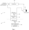
- Comme illustré sur la
figure 1 , le premier circuit, ou boucle de climatisation, 10 dédié à la régulation thermique de l'espace intérieur de l'habitacle et le second circuit 20 dédié à la gestion thermique de la batterie sont disposés en parallèle l'un de l'autre. - Le premier circuit 10 comprend de façon classique un compresseur 101 forçant la circulation de fluide réfrigérant dans cette boucle principale pour qu'il traverse un condenseur 102 avant de traverser un dispositif de détente, ou détendeur, 103 puis un évaporateur 104 permettant de refroidir un air destiné à circuler vers l'habitacle du véhicule, avant d'atteindre à nouveau le compresseur
101. Dans cette boucle principale, le fluide réfrigérant réalise ainsi un cycle thermodynamique dans lequel il évacue sa chaleur au niveau du condenseur 102, et dans lequel il capte la chaleur au niveau de l'évaporateur 104. Le compresseur 101 est par ailleurs apte à forcer la circulation de fluide réfrigérant dans le second circuit 20 dédié à la gestion thermique de la batterie, et notamment dans au moins un (en l'occurrence un) élément d'échange thermique 204 qui joue un rôle d'évaporateur, de sorte à ce que le fluide réfrigérant puisse absorber la chaleur émise par la batterie afin de la refroidir. - L'évaporateur 204 comprend un faisceau d'échange de chaleur composé de plaques ou de tubes à l'intérieur desquels circule le fluide réfrigérant.
- Cet évaporateur 204 peut comporter un certain nombre de passes correspondant au nombre de fois où le fluide réfrigérant traverse le faisceau d'échange de chaleur.
- Dans un cycle de refroidissement, en sortie cet évaporateur 204, le fluide réfrigérant est dans un état de vapeur surchauffée. Cette surchauffe est mise en œuvre afin que le fluide réfrigérant à l'état liquide ne pénètre pas dans le compresseur 101 du premier circuit de climatisation 10.
- Le fait d'amener le fluide réfrigérant dans un état de vapeur surchauffée s'effectue généralement lors de la dernière passe du fluide réfrigérant au sein de l'évaporateur 204, dite passe de sortie.
- Cette surchauffe du fluide réfrigérant entraîne néanmoins une diminution de l'efficacité de l'évaporateur 204 par rapport à sa capacité, car la dernière passe en son sein est dédiée en partie à la surchauffe du fluide réfrigérant.
- De plus, le fait de consacrer partiellement cette dernière passe à la surchauffe du fluide réfrigérant entraîne également une inhomogénéité de la température de l'évaporateur 204, cette dernière passe étant partiellement plus chaude.
- Le refroidissement de la batterie en contact thermique avec l'évaporateur 204 n'est donc pas uniforme.
- Ainsi, un des buts de l'invention est de remédier aux inconvénients de l'art antérieur.
- L'invention propose à cet effet un pack-batterie pour véhicule automobile comprenant au moins un élément de stockage d'énergie électrique, un boîtier (200) du pack-batterie et un dispositif de gestion thermique d'un pack-batterie pour véhicule automobile comprenant l'élément de stockage d'énergie électrique contenu dans le boitier (200), ledit dispositif de gestion thermique comportant au moins un évaporateur de batterie (204), en contact thermique avec ledit au moins un élément de stockage d'énergie électrique et dans lequel est destiné à circuler un fluide réfrigérant, et un dispositif de détente (203) relie fluidiquement audit au moins un évaporateur de batterie (204), ledit dispositif de gestion thermique étant caractérisé en ce qu'il comprend un échangeur de chaleur interne (205) solidaire du boitier (200) du pack-batterie et destine a surchauffer le fluide réfrigérant sortant dudit au moins un évaporateur de batterie (204), le dispositif de gestion comprenant au sein du boitier plusieurs plaques ou tubes de refroidissement (204'), dans lesquels circule le fluide réfrigérant et formant évaporateur et en ce que le dispositif de détente (203) est localise à l'intérieur du boitier (200).
- Selon l'invention, le dispositif de gestion thermique comprend un échangeur de chaleur interne solidaire du boîtier du pack-batterie et destiné à surchauffer le fluide réfrigérant sortant dudit au moins un évaporateur de batterie.
- L'invention propose ainsi d'ajouter un échangeur de chaleur interne au sein d'un pack-batterie, ou sur une paroi extérieure de ce dernier, à l'intérieur duquel sont logés un ou plusieurs évaporateurs de batterie en contact thermique avec une ou plusieurs cellules de batterie.
- L'échangeur de chaleur interne est relié à la sortie de l'évaporateur de sorte à assurer la surchauffe du fluide réfrigérant.
- Par conséquent, du fait que l'évaporateur n'est plus utilisé pour réaliser la surchauffe du fluide réfrigérant, on a une meilleure homogénéité de température sur toute la surface de l'évaporateur pour le refroidissement de la batterie au contact de ce dernier.
- En d'autres termes, l'évaporateur est plus efficace, du fait que la dernière passe du fluide réfrigérant en son sein n'est plus consacrée à la surchauffe du fluide réfrigérant, mais à un échange d'énergie calorifique standard.
- Ceci permet d'uniformiser le refroidissement de la batterie, tout en optimisant le fonctionnement et la durée de vie de la batterie. Selon un aspect particulier de l'invention, le dispositif de détente est situé en aval de l'échangeur de chaleur interne et en amont dudit au moins un évaporateur de batterie selon le sens d'écoulement du fluide réfrigérant.
- Selon un aspect particulier de l'invention le dispositif de gestion thermique selon remarquable en ce que le dispositif de détente est situé en aval de l'échangeur de chaleur interne et en amont dudit au moins un évaporateur de batterie selon le sens d'écoulement du fluide réfrigérant, et en ce que qu'il comprend un bloc de distribution et en ce que le dispositif de détente alimente en fluide réfrigérant les différentes plaques ou tubes de refroidissement via le bloc de distribution.
- Selon un aspect particulier de l'invention, le dispositif comprend en outre un compresseur et un condenseur placé en aval dudit compresseur, l'échangeur de chaleur interne étant placé en aval du condenseur et en amont du compresseur, et étant relié d'une part à une sortie de fluide réfrigérant du condenseur et d'autre part à une entrée de fluide réfrigérant du compresseur.
- On ajoute ainsi un échangeur de chaleur interne placé en amont du détendeur affecté à l'évaporateur de batterie sur le conduit de fluide réfrigérant en provenance du condenseur, et en amont du compresseur sur le conduit de fluide réfrigérant en provenance de l'évaporateur.
- Ainsi, le fluide réfrigérant en provenance de l'évaporateur de batterie passe par l'échangeur de chaleur interne avant de rejoindre l'entrée de fluide réfrigérant du compresseur.
- L'ajout d'un échangeur de chaleur interne permet une surchauffe avant l'entrée dans le compresseur et une augmentation de la puissance de l'évaporateur de batterie (du fait de la diminution de la température du fluide haute pression sortant du condenseur, avant l'entrée du détendeur affecté à l'évaporateur de batterie).
- Dans un mode de réalisation particulier de l'invention, l'échangeur de chaleur interne est localisé à l'intérieur du boîtier.
- Dans une variante, l'échangeur de chaleur interne est monté sur au moins une paroi extérieure dudit boîtier.
- Dans un autre mode de réalisation particulier de l'invention, le dispositif de détente est monté sur une paroi extérieure dudit boîtier. L'échangeur de chaleur interne est, par exemple, vissé ou clippé sur au moins une paroi intérieure ou extérieure du boîtier du pack-batterie.
- De façon avantageuse, le dispositif de détente est un détendeur thermostatique, un détendeur électronique ou un orifice tube.
- L'invention concerne également un système de conditionnement thermique d'un véhicule automobile comprenant :
- une boucle de climatisation dans laquelle circule un fluide réfrigérant et comprenant un compresseur, un condenseur, et un évaporateur d'habitacle permettant de refroidir un air destiné à circuler vers l'habitacle du véhicule,
- une branche dédiée à la gestion thermique d'au moins un élément de stockage d'énergie électrique d'un pack-batterie du véhicule et comprenant au moins un évaporateur dans lequel est destiné à circuler un fluide réfrigérant apte à échanger thermiquement avec ledit au moins un élément de stockage d'énergie électrique, dit évaporateur de batterie, et un dispositif de détente relié fluidiquement audit au moins un évaporateur de batterie, ladite branche comprenant un échangeur de chaleur interne solidaire du boîtier du pack- batterie et destiné à surchauffer le fluide réfrigérant sortant dudit au moins un évaporateur de batterie.
- D'autres caractéristiques et avantages de l'invention apparaîtront plus clairement à la lecture de la description suivante, donnée à titre d'exemple illustratif et non limitatif, et des dessins annexés, parmi lesquels :
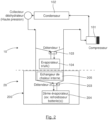
lafigure 1 montre une représentation schématique générale d'un système de conditionnement thermique d'un véhicule automobile électrique ou hybride selon l'art antérieur ; lafigure 2 montre une représentation schématique d'un système de conditionnement thermique d'un véhicule automobile électrique ou hybride dans lequel est mis en œuvre un dispositif de régulation thermique d'un pack- batterie selon l'invention ; - la
figure 3 montre une représentation schématique générale d'un pack-batterie et d'un dispositif de régulation thermique de batterie conforme à l'invention ; - la
figure 4 montre une représentation schématique générale d'un pack-batterie et d'un dispositif de régulation thermique de batterie selon l'invention - la
figure 5 montre une représentation schématique générale d'un pack-batterie et d'un dispositif de régulation thermique de batterie selon un autre mode de réalisation ne faisant pas partie de l'invention. - Dans la présente description, on entend par "batterie" un ensemble de cellules de stockage d'énergie électrique reliées électriquement entre elles de façon à créer un générateur électrique de tension et de capacité désirée, mais pourrait le cas échéant ne comprendre qu'une seule cellule de stockage d'énergie électrique.
- Ces cellules de stockage d'énergie électrique formant la batterie sont positionnées dans un boîtier de protection forment ce que l'on appelle un pack- batterie.
- Par ailleurs, on entend par « placé en amont » qu'un élément est placé avant un autre par rapport au sens de circulation du fluide frigorigène ou caloporteur.
- A contrario, on entend par « placé en aval » qu'un élément est placé après un autre par rapport au sens de circulation du fluide frigorigène ou caloporteur. On a représenté, sur la
figure 2 , un système de conditionnement thermique d'un véhicule automobile de type électrique ou hybride, qui est équipé d'une batterie pour sa propulsion. - Ce système de conditionnement thermique conforme à l'invention comprend une première boucle de climatisation 10 pour réguler thermiquement l'espace intérieur de l'habitacle du véhicule en délivrant un flux d'air intérieur à température désirée et dans laquelle circule un fluide réfrigérant.
- Cette première boucle de climatisation 10 comprend principalement un compresseur 101 forçant la circulation de fluide réfrigérant dans cette boucle pour qu'il traverse un condenseur 102 placé en aval dudit compresseur 101, avant de traverser un organe de détente ou détendeur 103 affecté à un évaporateur 104, dit évaporateur d'habitacle, qui est placé en aval dudit condenseur 102 et qui permet de refroidir un air destiné à circuler vers l'habitacle du véhicule,
- Dans cette première boucle de climatisation, le fluide réfrigérant réalise ainsi un cycle thermodynamique dans lequel il évacue sa chaleur au niveau du condenseur 102, et dans lequel il capte la chaleur au niveau de l'évaporateur 104.
- Comme cela est illustré sur la
figure 2 , le compresseur 101 est par ailleurs apte à forcer la circulation de fluide réfrigérant dans un second circuit, ou branche, 20 dédié à la gestion thermique de la batterie du véhicule, et notamment dans au moins un (en l'occurrence un) élément d'échange thermique qui joue un rôle d'évaporateur 204, de sorte à ce que le fluide réfrigérant puisse absorber la chaleur émise par la batterie afin de la refroidir. - La batterie (non représentée) est logée dans un boîtier 200 formant ainsi un pack-batterie.
- L'évaporateur 204 comprend un faisceau d'échange de chaleur composé de plaques ou de tubes à l'intérieur desquels circule le fluide réfrigérant. Cet évaporateur 204 peut comporter un certain nombre de passes correspondant au nombre de fois où le fluide réfrigérant traverse le faisceau d'échange de chaleur.
- Le dispositif de régulation thermique de la batterie comprend donc l'évaporateur 204 apte à échanger thermiquement avec la batterie du véhicule, un échangeur de chaleur interne 205 disposé au sein du boîtier 200 dans cet exemple et un dispositif de détente 203 affecté à l'évaporateur 204 situé en aval de l'échangeur de chaleur interne 205 et en amont de l'évaporateur 204.
- L'évaporateur 204 dédié à la batterie est donc relié à un circuit transportant le fluide réfrigérant en provenance de la boucle de climatisation 10.
- L'échangeur de chaleur interne 205 et l'évaporateur 204 de batteries sont raccordés en parallèle à l'évaporateur 104 d'habitacle.
- L'échangeur de chaleur interne 205 est placé en aval du condenseur 102 et en amont du compresseur 101, et est relié d'une part à une sortie de fluide réfrigérant du condenseur 102 et d'autre part à une entrée de fluide réfrigérant du compresseur 101.
- L'échangeur de chaleur interne 205 permet un échange de calories entre le fluide réfrigérant en provenance du condenseur 102 et le fluide réfrigérant en provenance de l'évaporateur 204 de batterie.
- Dans le mode de réalisation illustré sur la
figure 3 , le circuit de régulation thermique refroidit les cellules de batterie (non représentées) au moyen de plusieurs plaques ou tubes, d'échange thermique, en l'occurrence de refroidissement 204', dans lesquelles circule le fluide réfrigérant et formant évaporateur. - Selon l'exemple de réalisation présenté, quatre plaques ou séries de tubes, de refroidissement 204' sont disposées verticalement au sein du boîtier 200 au contact direct ou non des cellules pour les refroidir par conduction thermique. Toutefois, elles pourraient être disposées au fond du boîtier 200 de sorte que les cellules de batterie reposent sur chacune des plaques de refroidissement 204'.
- Les échanges thermiques entre la batterie et le dispositif de régulation thermique se font donc au niveau des plaques/ tubes de refroidissement 204'.
- Le nombre de plaques/tubes de refroidissement 204' n'est pas limité à celui illustré.
- Dans ce mode de réalisation, l'échangeur de chaleur interne 205 est disposé à l'interface du boîtier 200, en aval d'un bloc de connexion 206 au circuit de climatisation, et est relié à l'organe de détente 203 qui alimente en fluide réfrigérant les différentes plaques/tubes de refroidissement 204' via un bloc de distribution (représenté sur les
figures 4 et 5 ). - Lors du fonctionnement du dispositif de régulation thermique de la batterie, le fluide réfrigérant en phase gazeuse est comprimé par le compresseur 101 et circule vers le condenseur 102 pour son passage au moins en partie en phase liquide.
- Le fluide réfrigérant est ensuite détendu par l'organe de détente 203 et circule vers l'évaporateur 204 de batterie.
- En sortie de l'évaporateur 204 de batterie, le fluide réfrigérant est surchauffé par l'échangeur de chaleur interne 205 où il se transforme en phase gazeuse pour éviter l'absorption de liquide par le compresseur 101 et augmenter la durée de vie de ce dernier.
- Il n'y a donc pas de surchauffe à générer/gérer dans l'évaporateur 204 de batterie, constitué d'une ou plusieurs plaques/tubes de refroidissement, et donc pas de fluide réfrigérant en phase gazeuse dans ces plaques/tubes ce qui optimise l'efficacité de l'échange thermique des plaques/tubes de refroidissement avec la batterie. Selon diverses variantes, l'organe de détente est un détendeur thermostatique, un détendeur électronique ou un orifice tube (également appelé orifice calibré). Alors que dans les solutions de l'art antérieur, cet organe de détente est disposé sur une paroi du boîtier du pack-batterie, il peut être disposé, dans le cadre de l'invention, au sein du boîtier du pack-batterie.
- Le compresseur peut être de type mécanique à contrôle interne ou externe, de type électrique ou de type hybride mécanique-électrique.
- Dans le mode de réalisation illustré sur la
figure 4 , l'échangeur de chaleur interne 205, l'organe de détente 203, le bloc de distribution 203' et le ou les évaporateurs 204 sont disposés au sein du boîtier 200 du pack-batterie. Le bloc de connexion 206, qui est une interface présentant une entrée et une sortie de fluide réfrigérant, est relié à l'échangeur de chaleur interne 205 situé en aval. - Dans le mode de réalisation illustré sur la
figure 5 , l'échangeur de chaleur interne 205 et l'organe de détente 203 sont montés hors du boîtier 200 du pack- batterie sur les parois extérieures de ce dernier. Le bloc de distribution 203' et le ou les évaporateurs 204 sont disposés au sein du boîtier 200. Le bloc de connexion 206 est une interface présentant une entrée et une sortie de fluide réfrigérant, et est relié à l'échangeur de chaleur interne 205 situé en aval. - Dans les modes de réalisation des
figures 4 et 5 , l'échangeur de chaleur interne 205 est solidaire du boîtier 200. Pour ce faire, il est fixé de façon réversible sur ou dans le boîtier 200, par vissage ou clipsage par exemple. - L'échangeur de chaleur interne 205 peut être un échangeur coaxial constitué de deux tubes concentriques ou un échangeur à plaques, par exemple.
- Le diamètre externe de l'échangeur coaxial dépend de la puissance à évacuer.
- Lorsque cette puissance à évacuer est comprise entre 0 et 2.5 kW, le diamètre extérieur de l'échangeur coaxial est compris entre 8 et 12 mm, de préférence entre 8 et 10 mm. Lorsque la puissance à évacuer est comprise entre 2.5 kW et 5 kW, le diamètre extérieur de l'échangeur coaxial est compris entre 10 et 24 mm, de préférence entre 10 et 20 mm.
- Ces dimensions visent à limiter les pertes de charge dans l'échangeur de chaleur interne 205 de type coaxial pour optimiser la performance du dispositif de régulation thermique de la batterie.
- L'échangeur de chaleur interne 205 et l'organe de détente 203 peuvent être disposés au sein du pack-batterie ou montés solidaires, de façon réversible, sur une paroi (couvercle ou paroi latérale) du pack-batterie.
- Comme décrit précédemment, le fluide réfrigérant circulant à l'intérieur de la ou des plaques/tubes d'échange thermique du dispositif de gestion thermique peut absorber de la chaleur émise par les cellules électriques. Il peut également, si besoin est, apporter de la chaleur pour réchauffer les cellules électriques.
- Pour ce faire, la boucle de régulation thermique de la batterie comprend un dispositif de chauffage additionnel, utilisant par exemple des résistances électriques ou des résistances à coefficient de température positif.
- Un tel dispositif de chauffage additionnel permet réguler la température des cellules électriques, notamment par des températures basses en hiver, où il faut augmenter la température des cellules électriques avant de commencer à les charger.
- Ainsi, on voit bien que le dispositif de régulation/gestion thermique selon l'invention permet une meilleure homogénéité de température sur toute la surface de l'évaporateur pour le refroidissement et également d'avoir un évaporateur plus efficace et donc une meilleure gestion de la température du pack batteries.
- Le dispositif de régulation/gestion thermique de la batterie conforme à l'invention permet d'optimiser la durée de vie de la batterie, et d'assurer la fiabilité, l'autonomie, et la performance du véhicule. Les fluides réfrigérants utilisés peuvent être un gaz réfrigérant du type R134a, R1234yf, R744 ou équivalent.
- On notera que l'évaporateur 204 de batteries étant monté en parallèle par rapport à l'évaporateur 104 d'habitacle, ces deux évaporateurs peuvent fonctionner indépendamment l'un de l'autre.
- L'habitacle et le module de batteries peuvent donc être régulés thermiquement de manière indépendante.
- Par ailleurs, le circuit 20 dédié à la gestion thermique de la batterie du véhicule peut être mis en œuvre indépendamment d'une boucle de climatisation, et comprendre un compresseur et un condenseur dédiés uniquement audit circuit 20 de gestion thermique de la batterie.
- Dans ce cas, l'échangeur de chaleur interne est placé en aval du condenseur et en amont du compresseur, et est relié d'une part à une sortie de fluide réfrigérant du condenseur et d'autre part à une entrée de fluide réfrigérant du compresseur.
- La batterie comprend un assemblage de modules, eux-mêmes comprenant un assemblage de cellules électriques en série et/ou en parallèle.
- Les cellules électriques peuvent être de type cylindrique, prismatique ou souple (appelées "pouch-cells" en anglais).
- Par ailleurs, l'évaporateur de batterie peut être à plaques ou à tubes.
Claims (7)
- Pack-batterie pour véhicule automobile comprenant au moins un élément de stockage d'énergie électrique, un boîtier (200) du pack-batterie et un dispositif de gestion thermique d'un pack-batterie pour véhicule automobile comprenant l'élément de stockage d'énergie électrique contenu dans le boitier (200), ledit dispositif de gestion thermique comportant au moins un évaporateur de batterie (204), en contact thermique avec ledit au moins un élément de stockage d'énergie électrique et dans lequel est destiné à circuler un fluide réfrigérant, et un dispositif de détente (203) relié fluidiquement audit au moins un évaporateur de batterie (204), ledit dispositif de gestion thermique étant caractérisé en ce qu'il comprend un échangeur de chaleur interne (205) solidaire du boitier (200) du pack-batterie et destiné à surchauffer le fluide réfrigérant sortant dudit au moins un évaporateur de batterie (204), le dispositif de gestion comprenant au sein du boitier plusieurs plaques ou tubes de refroidissement (204'), dans lesquels circule le fluide réfrigérant et formant évaporateur et en ce que le dispositif de détente (203) est localisé à l'intérieur du boitier (200).
- Pack-batterie selon la revendication 1, caractérisé en ce que le dispositif de détente (203) est situé en aval de l'échangeur de chaleur interne (205) et en amont dudit au moins un évaporateur de batterie (204) selon le sens d'écoulement du fluide réfrigérant, et en ce qu'il comprend un bloc de distribution (203') et en ce que le dispositif de détente (203) alimente en fluide réfrigérant les différentes plaques ou tubes de refroidissement (204') via le bloc de distribution (203'), le bloc de distribution étant situé dans le boîtier.
- Pack-batterie selon la revendication 1 ou 2, caractérisé en ce qu'il comprend en outre un compresseur (101) et un condenseur (102) placé en aval dudit compresseur (101), l'échangeur de chaleur interne (205) étant placé place en aval du condenseur (102) et en amont du compresseur (101), et étant relié d'une part à une sortie de fluide réfrigérant du condenseur (102) et d'autre part à une entrée de fluide réfrigérant du compresseur (101).
- Pack-batterie selon l'une des revendications 1 à 3, caractérisé en ce que l'échangeur de chaleur interne (205) est localisé à l'intérieur du boitier (200).
- Pack-batterie selon l'une des revendications 1 à 3, caractérisé en ce que l'échangeur de chaleur interne (205) est monté sur au moins une paroi extérieure dudit boitier (200).
- Pack-batterie selon la revendication 5, caractérisé en ce que le dispositif de détente (205) est monté sur une paroi extérieure dudit boitier (200).
- Pack-batterie selon l'une des revendications 1 à 6, caractérisé en ce que le dispositif de détente (205) est un détendeur thermostatique, un détendeur électronique ou un orifice tube.
Applications Claiming Priority (2)
| Application Number | Priority Date | Filing Date | Title |
|---|---|---|---|
| FR1753295A FR3065325A1 (fr) | 2017-04-14 | 2017-04-14 | Dispositif de gestion thermique d'un pack-batterie |
| PCT/FR2018/050807 WO2018189449A1 (fr) | 2017-04-14 | 2018-03-30 | Dispositif de gestion thermique d'un pack-batterie |
Publications (2)
| Publication Number | Publication Date |
|---|---|
| EP3610534A1 EP3610534A1 (fr) | 2020-02-19 |
| EP3610534B1 true EP3610534B1 (fr) | 2025-04-30 |
Family
ID=59070877
Family Applications (1)
| Application Number | Title | Priority Date | Filing Date |
|---|---|---|---|
| EP18722668.3A Active EP3610534B1 (fr) | 2017-04-14 | 2018-03-30 | Dispositif de gestion thermique d'un pack-batterie |
Country Status (5)
| Country | Link |
|---|---|
| EP (1) | EP3610534B1 (fr) |
| JP (1) | JP7062683B2 (fr) |
| CN (1) | CN110521053A (fr) |
| FR (1) | FR3065325A1 (fr) |
| WO (1) | WO2018189449A1 (fr) |
Families Citing this family (3)
| Publication number | Priority date | Publication date | Assignee | Title |
|---|---|---|---|---|
| FR3115732B1 (fr) * | 2020-11-04 | 2022-10-14 | Valeo Systemes Thermiques | Module de refroidissement pour véhicule automobile électrique ou hybride à turbomachine tangentielle avec échangeur thermique supplémentaire |
| CN113193267A (zh) * | 2021-06-08 | 2021-07-30 | 奇瑞商用车(安徽)有限公司 | 一种电池包液冷系统及其水温控制方法 |
| EP4468260A1 (fr) | 2023-05-26 | 2024-11-27 | MyScript | Reconnaissance d'entrée manuscrite |
Family Cites Families (13)
| Publication number | Priority date | Publication date | Assignee | Title |
|---|---|---|---|---|
| JP2003097857A (ja) * | 2001-07-12 | 2003-04-03 | Calsonic Kansei Corp | 冷房サイクル |
| US9283826B2 (en) * | 2007-11-13 | 2016-03-15 | Mahle International Gmbh | Device for cooling a heat source of a motor vehicle |
| US20090249802A1 (en) * | 2008-04-04 | 2009-10-08 | Gm Global Technology Operations, Inc. | Vehicle HVAC and Battery Thermal Management |
| DE102008035216A1 (de) * | 2008-04-19 | 2009-10-22 | Daimler Ag | Kühlanordnung und Verfahren zum Kühlen eines temperaturempfindlichen Aggregats eines Kraftfahrzeugs |
| JP2011049139A (ja) * | 2009-07-31 | 2011-03-10 | Sanyo Electric Co Ltd | バッテリー装置 |
| CN102104181A (zh) * | 2009-12-18 | 2011-06-22 | 上海汽车集团股份有限公司 | 动力蓄电池热管理系统及汽车 |
| DE102011053894A1 (de) * | 2010-11-23 | 2012-05-24 | Visteon Global Technologies, Inc. | Kälteanlage mit Kältemittelverdampferanordnung und Verfahren zur parallelen Luft- und Batteriekontaktkühlung |
| HUE066380T2 (hu) * | 2010-12-29 | 2024-08-28 | Byd Co Ltd | Akkumulátormodul, akkumulátor-hõmérséklet kezelõ rendszer és az ezt tartalmazó jármû |
| FR2976224B1 (fr) * | 2011-06-08 | 2013-05-31 | Valeo Systemes Thermiques | Systeme de conditionnement thermique d'un habitacle et d'une batterie electrique |
| JP2013060065A (ja) * | 2011-09-12 | 2013-04-04 | Daikin Industries Ltd | 自動車用温調システム |
| JP2013164944A (ja) * | 2012-02-10 | 2013-08-22 | Nissan Motor Co Ltd | バッテリパック構造 |
| JP5974960B2 (ja) * | 2013-04-08 | 2016-08-23 | 株式会社デンソー | 電池温度調整装置 |
| FR3028016A1 (fr) * | 2014-10-30 | 2016-05-06 | Valeo Systemes Thermiques | Dispositif de gestion thermique de vehicule automobile |
-
2017
- 2017-04-14 FR FR1753295A patent/FR3065325A1/fr not_active Withdrawn
-
2018
- 2018-03-30 JP JP2019555791A patent/JP7062683B2/ja active Active
- 2018-03-30 CN CN201880025020.0A patent/CN110521053A/zh active Pending
- 2018-03-30 WO PCT/FR2018/050807 patent/WO2018189449A1/fr not_active Ceased
- 2018-03-30 EP EP18722668.3A patent/EP3610534B1/fr active Active
Also Published As
| Publication number | Publication date |
|---|---|
| WO2018189449A1 (fr) | 2018-10-18 |
| JP2020517065A (ja) | 2020-06-11 |
| JP7062683B2 (ja) | 2022-05-06 |
| CN110521053A (zh) | 2019-11-29 |
| EP3610534A1 (fr) | 2020-02-19 |
| FR3065325A1 (fr) | 2018-10-19 |
Similar Documents
| Publication | Publication Date | Title |
|---|---|---|
| EP2370280B1 (fr) | Dispositif pour refroidir les batteries d'un vehicule notamment electrique et vehicule equipe d'un tel dispositif | |
| EP3735358B1 (fr) | Circuit de conditionnement thermique | |
| FR3070557A1 (fr) | Dispositif de connexion electrique pour vehicule automobile refroidi par un circuit de fluide refrigerant | |
| EP3732741A1 (fr) | Systeme de refroidissement d'au moins une batterie de vehicule automobile | |
| WO2016001418A1 (fr) | Echangeur thermique à double circulation et installation de gestion thermique correspondante | |
| FR3070556B1 (fr) | Dispositif de connexion electrique pour vehicule refroidi par un circuit de fluide caloporteur | |
| EP3610534B1 (fr) | Dispositif de gestion thermique d'un pack-batterie | |
| FR2975230A1 (fr) | Pack batterie avec dispositif de regulation thermique associe | |
| WO2019155179A1 (fr) | Systeme de refroidissement d'au moins une batterie de véhicule automobile | |
| EP3781882B1 (fr) | Dispositif de conditionnement thermique pour véhicule automobile | |
| FR3135422A1 (fr) | Système de conditionnement thermique comprenant un module de gestion des fluides pour un véhicule notamment automobile | |
| EP3516318A2 (fr) | Dispositif de regulation thermique | |
| WO2018142090A1 (fr) | Circuit de gestion thermique et échangeur thermique associé | |
| FR3063182B1 (fr) | Systeme de conditionnement thermique d'un vehicule automobile mettant en oeuvre un dispositif de gestion thermique d'un pack-batterie | |
| WO2020115428A1 (fr) | Batterie modulaire comprenant un systeme de conditionnement thermique | |
| FR3065796A1 (fr) | Echangeur thermique mis en œuvre dans un circuit de regulation thermique d'un pack-batterie de vehicule automobile | |
| FR3070330B1 (fr) | Connecteur electrique participant a une charge de batterie de vehicule et comprenant un element de traitement thermique | |
| FR3101731A1 (fr) | « Dispositif de refroidissement d’un élément électrique susceptible de dégager de la chaleur en fonctionnement » | |
| WO2019069018A1 (fr) | Boîtier d'un pack-batterie de véhicule automobile | |
| EP3396290A1 (fr) | Module thermique comprenant un boîtier et un echangeur thermique | |
| EP3747080B1 (fr) | Procédé de refroidissement d'un dispositif de stockage électrique équipant un véhicule | |
| FR3073609B1 (fr) | Canal pour echangeur thermique d'un vehicule automobile | |
| FR2819344A1 (fr) | Vehicule comportant une batterie d'accumulateurs refroidie par un dispositif de climatisation | |
| EP4403391A1 (fr) | Systeme de pompe a chaleur | |
| FR3140996A1 (fr) | Dispositif de régulation de température d’une pluralité d’éléments électriques et/ou électroniques |
Legal Events
| Date | Code | Title | Description |
|---|---|---|---|
| STAA | Information on the status of an ep patent application or granted ep patent |
Free format text: STATUS: UNKNOWN |
|
| STAA | Information on the status of an ep patent application or granted ep patent |
Free format text: STATUS: THE INTERNATIONAL PUBLICATION HAS BEEN MADE |
|
| PUAI | Public reference made under article 153(3) epc to a published international application that has entered the european phase |
Free format text: ORIGINAL CODE: 0009012 |
|
| STAA | Information on the status of an ep patent application or granted ep patent |
Free format text: STATUS: REQUEST FOR EXAMINATION WAS MADE |
|
| 17P | Request for examination filed |
Effective date: 20191009 |
|
| AK | Designated contracting states |
Kind code of ref document: A1 Designated state(s): AL AT BE BG CH CY CZ DE DK EE ES FI FR GB GR HR HU IE IS IT LI LT LU LV MC MK MT NL NO PL PT RO RS SE SI SK SM TR |
|
| AX | Request for extension of the european patent |
Extension state: BA ME |
|
| DAV | Request for validation of the european patent (deleted) | ||
| DAX | Request for extension of the european patent (deleted) | ||
| STAA | Information on the status of an ep patent application or granted ep patent |
Free format text: STATUS: EXAMINATION IS IN PROGRESS |
|
| 17Q | First examination report despatched |
Effective date: 20230420 |
|
| P01 | Opt-out of the competence of the unified patent court (upc) registered |
Effective date: 20230528 |
|
| GRAP | Despatch of communication of intention to grant a patent |
Free format text: ORIGINAL CODE: EPIDOSNIGR1 |
|
| STAA | Information on the status of an ep patent application or granted ep patent |
Free format text: STATUS: GRANT OF PATENT IS INTENDED |
|
| INTG | Intention to grant announced |
Effective date: 20241202 |
|
| GRAS | Grant fee paid |
Free format text: ORIGINAL CODE: EPIDOSNIGR3 |
|
| GRAA | (expected) grant |
Free format text: ORIGINAL CODE: 0009210 |
|
| STAA | Information on the status of an ep patent application or granted ep patent |
Free format text: STATUS: THE PATENT HAS BEEN GRANTED |
|
| AK | Designated contracting states |
Kind code of ref document: B1 Designated state(s): AL AT BE BG CH CY CZ DE DK EE ES FI FR GB GR HR HU IE IS IT LI LT LU LV MC MK MT NL NO PL PT RO RS SE SI SK SM TR |
|
| REG | Reference to a national code |
Ref country code: CH Ref legal event code: EP Ref country code: GB Ref legal event code: FG4D Free format text: NOT ENGLISH |
|
| REG | Reference to a national code |
Ref country code: IE Ref legal event code: FG4D Free format text: LANGUAGE OF EP DOCUMENT: FRENCH |
|
| REG | Reference to a national code |
Ref country code: DE Ref legal event code: R096 Ref document number: 602018081493 Country of ref document: DE |
|
| REG | Reference to a national code |
Ref country code: NL Ref legal event code: MP Effective date: 20250430 |
|
| REG | Reference to a national code |
Ref country code: AT Ref legal event code: MK05 Ref document number: 1790953 Country of ref document: AT Kind code of ref document: T Effective date: 20250430 |
|
| PG25 | Lapsed in a contracting state [announced via postgrant information from national office to epo] |
Ref country code: FI Free format text: LAPSE BECAUSE OF FAILURE TO SUBMIT A TRANSLATION OF THE DESCRIPTION OR TO PAY THE FEE WITHIN THE PRESCRIBED TIME-LIMIT Effective date: 20250430 Ref country code: PT Free format text: LAPSE BECAUSE OF FAILURE TO SUBMIT A TRANSLATION OF THE DESCRIPTION OR TO PAY THE FEE WITHIN THE PRESCRIBED TIME-LIMIT Effective date: 20250901 Ref country code: ES Free format text: LAPSE BECAUSE OF FAILURE TO SUBMIT A TRANSLATION OF THE DESCRIPTION OR TO PAY THE FEE WITHIN THE PRESCRIBED TIME-LIMIT Effective date: 20250430 |
|
| REG | Reference to a national code |
Ref country code: LT Ref legal event code: MG9D |
|
| PG25 | Lapsed in a contracting state [announced via postgrant information from national office to epo] |
Ref country code: GR Free format text: LAPSE BECAUSE OF FAILURE TO SUBMIT A TRANSLATION OF THE DESCRIPTION OR TO PAY THE FEE WITHIN THE PRESCRIBED TIME-LIMIT Effective date: 20250731 Ref country code: NO Free format text: LAPSE BECAUSE OF FAILURE TO SUBMIT A TRANSLATION OF THE DESCRIPTION OR TO PAY THE FEE WITHIN THE PRESCRIBED TIME-LIMIT Effective date: 20250730 |
|
| PG25 | Lapsed in a contracting state [announced via postgrant information from national office to epo] |
Ref country code: PL Free format text: LAPSE BECAUSE OF FAILURE TO SUBMIT A TRANSLATION OF THE DESCRIPTION OR TO PAY THE FEE WITHIN THE PRESCRIBED TIME-LIMIT Effective date: 20250430 Ref country code: NL Free format text: LAPSE BECAUSE OF FAILURE TO SUBMIT A TRANSLATION OF THE DESCRIPTION OR TO PAY THE FEE WITHIN THE PRESCRIBED TIME-LIMIT Effective date: 20250430 |
|
| PG25 | Lapsed in a contracting state [announced via postgrant information from national office to epo] |
Ref country code: BG Free format text: LAPSE BECAUSE OF FAILURE TO SUBMIT A TRANSLATION OF THE DESCRIPTION OR TO PAY THE FEE WITHIN THE PRESCRIBED TIME-LIMIT Effective date: 20250430 |
|
| PG25 | Lapsed in a contracting state [announced via postgrant information from national office to epo] |
Ref country code: HR Free format text: LAPSE BECAUSE OF FAILURE TO SUBMIT A TRANSLATION OF THE DESCRIPTION OR TO PAY THE FEE WITHIN THE PRESCRIBED TIME-LIMIT Effective date: 20250430 |
|
| PG25 | Lapsed in a contracting state [announced via postgrant information from national office to epo] |
Ref country code: AT Free format text: LAPSE BECAUSE OF FAILURE TO SUBMIT A TRANSLATION OF THE DESCRIPTION OR TO PAY THE FEE WITHIN THE PRESCRIBED TIME-LIMIT Effective date: 20250430 |
|
| PG25 | Lapsed in a contracting state [announced via postgrant information from national office to epo] |
Ref country code: RS Free format text: LAPSE BECAUSE OF FAILURE TO SUBMIT A TRANSLATION OF THE DESCRIPTION OR TO PAY THE FEE WITHIN THE PRESCRIBED TIME-LIMIT Effective date: 20250731 |
|
| PG25 | Lapsed in a contracting state [announced via postgrant information from national office to epo] |
Ref country code: IS Free format text: LAPSE BECAUSE OF FAILURE TO SUBMIT A TRANSLATION OF THE DESCRIPTION OR TO PAY THE FEE WITHIN THE PRESCRIBED TIME-LIMIT Effective date: 20250830 |
|
| PG25 | Lapsed in a contracting state [announced via postgrant information from national office to epo] |
Ref country code: LV Free format text: LAPSE BECAUSE OF FAILURE TO SUBMIT A TRANSLATION OF THE DESCRIPTION OR TO PAY THE FEE WITHIN THE PRESCRIBED TIME-LIMIT Effective date: 20250430 |
|
| PG25 | Lapsed in a contracting state [announced via postgrant information from national office to epo] |
Ref country code: SM Free format text: LAPSE BECAUSE OF FAILURE TO SUBMIT A TRANSLATION OF THE DESCRIPTION OR TO PAY THE FEE WITHIN THE PRESCRIBED TIME-LIMIT Effective date: 20250430 Ref country code: DK Free format text: LAPSE BECAUSE OF FAILURE TO SUBMIT A TRANSLATION OF THE DESCRIPTION OR TO PAY THE FEE WITHIN THE PRESCRIBED TIME-LIMIT Effective date: 20250430 |
|
| PG25 | Lapsed in a contracting state [announced via postgrant information from national office to epo] |
Ref country code: CZ Free format text: LAPSE BECAUSE OF FAILURE TO SUBMIT A TRANSLATION OF THE DESCRIPTION OR TO PAY THE FEE WITHIN THE PRESCRIBED TIME-LIMIT Effective date: 20250430 |
|
| PG25 | Lapsed in a contracting state [announced via postgrant information from national office to epo] |
Ref country code: EE Free format text: LAPSE BECAUSE OF FAILURE TO SUBMIT A TRANSLATION OF THE DESCRIPTION OR TO PAY THE FEE WITHIN THE PRESCRIBED TIME-LIMIT Effective date: 20250430 |
|
| PG25 | Lapsed in a contracting state [announced via postgrant information from national office to epo] |
Ref country code: SK Free format text: LAPSE BECAUSE OF FAILURE TO SUBMIT A TRANSLATION OF THE DESCRIPTION OR TO PAY THE FEE WITHIN THE PRESCRIBED TIME-LIMIT Effective date: 20250430 Ref country code: RO Free format text: LAPSE BECAUSE OF FAILURE TO SUBMIT A TRANSLATION OF THE DESCRIPTION OR TO PAY THE FEE WITHIN THE PRESCRIBED TIME-LIMIT Effective date: 20250430 |
|
| PG25 | Lapsed in a contracting state [announced via postgrant information from national office to epo] |
Ref country code: IT Free format text: LAPSE BECAUSE OF FAILURE TO SUBMIT A TRANSLATION OF THE DESCRIPTION OR TO PAY THE FEE WITHIN THE PRESCRIBED TIME-LIMIT Effective date: 20250430 |
|
| REG | Reference to a national code |
Ref country code: DE Ref legal event code: R097 Ref document number: 602018081493 Country of ref document: DE |
|
| PLBE | No opposition filed within time limit |
Free format text: ORIGINAL CODE: 0009261 |
|
| STAA | Information on the status of an ep patent application or granted ep patent |
Free format text: STATUS: NO OPPOSITION FILED WITHIN TIME LIMIT |
|
| REG | Reference to a national code |
Ref country code: CH Ref legal event code: L10 Free format text: ST27 STATUS EVENT CODE: U-0-0-L10-L00 (AS PROVIDED BY THE NATIONAL OFFICE) Effective date: 20260311 |
|
| 26N | No opposition filed |
Effective date: 20260202 |
|
| PGFP | Annual fee paid to national office [announced via postgrant information from national office to epo] |
Ref country code: DE Payment date: 20260313 Year of fee payment: 9 |