EP3610258B1 - Optical detection of air bubbles in either saline or blood or a mixture of both - Google Patents
Optical detection of air bubbles in either saline or blood or a mixture of both Download PDFInfo
- Publication number
- EP3610258B1 EP3610258B1 EP18785187.8A EP18785187A EP3610258B1 EP 3610258 B1 EP3610258 B1 EP 3610258B1 EP 18785187 A EP18785187 A EP 18785187A EP 3610258 B1 EP3610258 B1 EP 3610258B1
- Authority
- EP
- European Patent Office
- Prior art keywords
- light
- wavelength
- photosensor
- absorbance
- led
- Prior art date
- Legal status (The legal status is an assumption and is not a legal conclusion. Google has not performed a legal analysis and makes no representation as to the accuracy of the status listed.)
- Active
Links
Images


Classifications
-
- A—HUMAN NECESSITIES
- A61—MEDICAL OR VETERINARY SCIENCE; HYGIENE
- A61M—DEVICES FOR INTRODUCING MEDIA INTO, OR ONTO, THE BODY; DEVICES FOR TRANSDUCING BODY MEDIA OR FOR TAKING MEDIA FROM THE BODY; DEVICES FOR PRODUCING OR ENDING SLEEP OR STUPOR
- A61M1/00—Suction or pumping devices for medical purposes; Devices for carrying-off, for treatment of, or for carrying-over, body-liquids; Drainage systems
- A61M1/36—Other treatment of blood in a by-pass of the natural circulatory system, e.g. temperature adaptation, irradiation ; Extra-corporeal blood circuits
- A61M1/3621—Extra-corporeal blood circuits
- A61M1/3626—Gas bubble detectors
-
- G—PHYSICS
- G01—MEASURING; TESTING
- G01N—INVESTIGATING OR ANALYSING MATERIALS BY DETERMINING THEIR CHEMICAL OR PHYSICAL PROPERTIES
- G01N33/00—Investigating or analysing materials by specific methods not covered by groups G01N1/00 - G01N31/00
- G01N33/48—Biological material, e.g. blood, urine; Haemocytometers
- G01N33/483—Physical analysis of biological material
- G01N33/487—Physical analysis of biological material of liquid biological material
- G01N33/49—Blood
-
- A—HUMAN NECESSITIES
- A61—MEDICAL OR VETERINARY SCIENCE; HYGIENE
- A61M—DEVICES FOR INTRODUCING MEDIA INTO, OR ONTO, THE BODY; DEVICES FOR TRANSDUCING BODY MEDIA OR FOR TAKING MEDIA FROM THE BODY; DEVICES FOR PRODUCING OR ENDING SLEEP OR STUPOR
- A61M2205/00—General characteristics of the apparatus
- A61M2205/33—Controlling, regulating or measuring
- A61M2205/3306—Optical measuring means
- A61M2205/3313—Optical measuring means used specific wavelengths
Definitions
- kidney failure or partial kidney failure typically undergo hemodialysis treatment, often at a hemodialysis treatment center or clinic.
- kidneys maintain the body's internal equilibrium of water and minerals (e.g., sodium, potassium, chloride, calcium, phosphorous, magnesium, and sulfate).
- the kidneys also function as part of the endocrine system to produce the hormone erythropoietin as well as other hormones.
- Hemodialysis is an imperfect treatment to replace kidney function, in part, because it does not correct the endocrine functions of the kidney.
- blood is taken from a patient through an intake needle (or catheter) which draws blood from an artery located in a specific accepted access location (arm, thigh, subclavian, etc.).
- the drawn blood is pumped through extracorporeal tubing via a peristaltic pump, and then through a dialyzer which removes unwanted toxins such as blood urea, nitrogen, potassium, and excess water from the blood.
- a dialyzer which removes unwanted toxins such as blood urea, nitrogen, potassium, and excess water from the blood.
- Fresh dialysate liquid which is a solution of chemicals and water, flows through the dialyzer in the direction opposite the blood flow.
- dialysate As the dialysate flows through the dialyzer, it surrounds the straw-like membranes in the dialyzer.
- the fresh dialysate collects excess impurities passing through the straw-like tubes by diffusion, and also collects excess water through an ultrafiltration process due to a pressure drop across the membranes.
- the used dialysate exits the dialyzer with the excess fluids and toxins via an output tube, thus cleansing the blood flowing through the dialyzer.
- the dialyzed blood then flows out of the dialyzer via tubing and a needle (or catheter) back into the patient.
- a heparin drip or pump is provided along the extracorporeal blood flow loop in order to prevent clotting during the hemodialysis process.
- Hemodialysis has an acute impact on the fluid balance of the body due in part to the rapid change in circulating blood volume.
- intravascular blood volume decreases.
- the resulting imbalance has been linked to complications such as hypotension, loss of consciousness, headaches, vomiting, dizziness and cramps experienced by the patient, both during and after dialysis treatments.
- Continuous quantitative measurement of parameters relating to the circulating blood volume (in real-time) during hemodialysis reduces the chance of dialysisinduced hypotension, and otherwise optimizes dialysis therapy regimes by controlling fluid balance and aiding in achieving the appropriate dry weight for the patient.
- US 2012/0095306 A1 and US 5,589,935 A are referred to as prior art.
- US 2012/0095306 describes a method of detecting gas bubbles in a living body, comprising: transmitting at least one original electromagnetic signal to a body portion; detecting a signal modulated by a flow of blood in said body portion; and analyzing a perturbation in said signal to determine at least one of an existence and a property of a bubble in said blood flow.
- One embodiment of the disclosure provides a method according to claim 1.
- Another embodiment of the disclosure provides a system according to claim 8.
- Yet another embodiment of the disclosure provides a non-transitory computer-readable medium having processor-executable instructions according to claim 12.
- Optional features are mentioned in the dependent claims 2-7,9-11 and 13-14.
- occlusion of an arterial blood access line due to blood flow at high flow rates may result in very low negative pressures ( ⁇ 200 mmHg) which would result in degassing of the blood.
- air bubble detection is important for indicating whether an arterial occlusion has occurred.
- One way of optically detecting air bubbles is with a single light intensity wavelength. The optical air bubble detection on the arterial line can thus be used for indicating an arterial occlusion event and alarming a user. While optical air bubble detection is desirable, and can be achieved with a single light intensity wavelength, it is affected by several factors affecting the single light wavelength absorbance.
- Single light wavelength absorbance is affected by the color of the medium or blood, which varies significantly based on the blood hematocrit concentration and oxygenation level.
- Single light wavelength is also affected by sensor to sensor variability across multiple sensors.
- a sensor includes a single wavelength source or emitter and a single wavelength detector.
- Sensor to sensor variability may be reduced through a self-normalization step where sensor measurements are normalized relative to a baseline of its measurement. For example, an empty tubing may be used with a sensor to characterize the sensor's profile while adjusting light input to the sensor. This self-normalization or sensor calibration can be performed on each source-detector combination to ensure signal integrity and sensor response at wavelength of interest.
- the disposable tubing that contains blood and through which the optical detection is taking place undergoes discoloration and loses some of its transparency over time, thus affecting measurements relying on single light wavelength absorbance.
- Other factors affecting single light wavelength absorbance include transient effects during dialysis. For example, when a saline solution dose is introduced and mixes with blood, the blood becomes diluted the color of the medium contained in the tubing lightens. Furthermore, when the saline delivery ends, and blood returns to the tubing mixing with saline currently in the tubing, the color of the medium contained in the tubing darkens.
- Saline delivery is typically clinically introduced during dialysis treatment in order to deliver medications to the patient, or in the case of a patient suffering from hypovolemia, saline is introduced to allow for rapid patient recovery.
- Such variability in factors affecting the absolute intensity of light absorption makes the detection of air based purely on intensity level of light of a single wavelength challenging and difficult to adapt with the various factors.
- an optical sensor typically interprets detection of blood when the single wavelength light is mostly absorbed (or equivalently reduced transmission of light), thus resulting in a low-range sensor output.
- the presence of air in the tubing produces scattering, which also reduces transmission, but not as much as blood, and thus resulting in a mid-range sensor output.
- a single wavelength optical sensor may then be used to obtain "typical" levels of sensor outputs for blood, air, and saline in order to interpret contents of the tubing during dialysis.
- Embodiments of the disclosure provide an improved methodology for detection of a transient air bubble by removing one or more effects of common mode factors affecting the absorbance of the light, such as, medium color, tubing color, angle of illumination, or temperature of the optical detector.
- the methodology involves using a normalized ratio ( R ) of the absorbance intensity of two light wavelengths through the medium.
- R normalized ratio
- FIG. 1 is a perspective view of a typical patient undergoing hemodialysis treatment with a non-invasive, optical blood monitor monitoring the patient's blood in real-time as it passes through extracorporeal tubing in the hemodialysis system.
- the environment illustrated in FIG. 1 is usable with exemplary embodiments of the present disclosure. Further, it will be appreciated that the environment shown in FIG. 1 is merely exemplary, and that the principles discussed herein with respect to exemplary embodiments of the present disclosure may be implemented in other environments as well.
- FIG. 1 illustrates a patient 10 undergoing hemodialysis treatment using a conventional hemodialysis system 12, as well as a non-invasive, optical blood monitor 14.
- a typical hemodialysis clinic will have several hemodialysis systems 12 for treating patients on a Monday-Wednesday-Friday schedule or a Tuesday-Thursday-Saturday schedule. While the invention is not limited to the number of hemodialysis systems located at a clinic, or the specific type of hemodialysis system, the general operation of the hemodialysis system 12 is helpful for understanding the environment in which the invention is intended to operate.
- An input needle or catheter 16 is inserted into an access site of the patient 10, such as in the arm, and is connected to extracorporeal tubing 18 that leads to a peristaltic pump 20 and then to a dialyzer or blood filter 22.
- the dialyzer 22 removes toxins and excess fluid from the patient's blood.
- the dialyzed blood is returned from the dialyzer 22 through extracorporeal tubing 24 and return needle or catheter 26.
- the extracorporeal blood flow may additionally receive a heparin drip to prevent clotting.
- the excess fluids and toxins are removed by clean dialysate liquid which is supplied to the dialyzer 22 via tube 28 and removed for disposal via tube 30.
- a typical hemodialysis treatment session takes about 3 to 5 hours in the United States.
- the optical blood monitor 14 includes a blood chamber 32, an optical blood sensor assembly 34, and a controller 35.
- the blood chamber 32 is preferably located in line with the extracorporeal tubing 18 upstream of the dialyzer 22. Blood from the peristaltic pump 20 flows through the tubing 18 into the blood chamber 32.
- the preferred sensor assembly 34 includes LED photo emitters that emit light at optical wavelengths.
- the blood chamber 32 includes lenses so that the emitters and detectors of the sensor assembly 34 can view the blood flowing through the blood chamber 32, and determine whether a transient air bubble is detected in the blood.
- the optical blood monitor includes an optical blood sensor assembly and a controller and does not include a blood chamber.
- the optical blood sensor assembly clasps onto the extracorporeal tubing upstream of the dialyzer.
- the blood sensor assembly includes LED photo emitters that emit light in optical wavelengths including red light, infrared light, ultraviolet light, blue light, green light, and/or any wavelength in the optical spectrum. The emitted light travels from the LED photo emitters through the extracorporeal tubing to light detectors (e.g. photodiodes) also included in the optical blood sensor assembly.
- FIG. 2 illustrates an exemplary system 200 that may be used to measure blood constituents using an optical blood sensor assembly according to some embodiments of the disclosure.
- An LED current driver 202 produces multiple currents to drive an LED array 204.
- the LED array 204 contains LED1 to LED N .
- Each LED in the LED array 204 operates at a different wavelength, and the LED current driver 202 is configured to provide power to turn ON or turn OFF each LED in the LED array 204.
- FIG. 2 shows that processor 216 controls the LED current driver 202, so in some embodiments, the processor 216 may determine which LEDs should be turned ON at a certain time during measurement.
- Light from the LED array 204 is incident on a blood container 208, passes through a blood flow path 206, and is detected at a photosensor 210 (or "photodetector") which may be a photodiode.
- the blood container 208 may be, for example, a blood chamber 32 located in line with an extracorporeal tubing 18, or may be, for example, the extracorporeal tubing 18 itself.
- the photosensor 210 may be one or more photosensors sensitive to wavelengths emitted by the LED array 204.
- the photosensor 210 collects and integrates detected LED light and generates a current.
- the current is then amplified and filtered by the receiver 212.
- the receiver 212 may also convert the amplified and filtered current from an analog signal to a digital signal, providing the digital signal to the processor 216
- the processor 216 is designed to interface with other electronic components allowing input and output communication of signals to and from the optical blood sensor assembly.
- every other component identified in system 200 may be part of a optical blood sensor assembly, for example, an optical blood sensor assembly 34 as depicted in FIG. 1 .
- the optical blood sensor assembly 34 may communicate with a controller 35 for displaying system outputs and/or receiving command signals or calibration signals.
- the processor 216 performs calculations and analyses based on the digital signal received from the receiver 212 and determines whether air bubbles are present in the blood flow path 206. In other embodiments, the processor 216 may provide the digital signal received from the receiver 212 to an external computing device using the input/output communication channels so that the external computing device, for example, controller 35, determines whether air bubbles are present in the blood flow path 206.
- Processor 216 may be a microprocessor, a microcontroller, a field programmable gate array (FPGA), a complex programmable logic device (CPLD), an application specific integrated circuit (ASIC), etc.
- FIG. 2A illustrates another exemplary system 201 that may be used to measure blood constituents using an optical blood sensor assembly according to some embodiments of the disclosure.
- the system 201 includes a processor 217, LED current driver 203, a multi-wavelength LED 205, a blood flow path 207, a tubing 209, a wideband photosensor 211, and a receiver/signal processor 213.
- the multi-wavelength LED 205 may generate more than one wavelength, and the wideband photosensor 211 is sensitive to the more than one wavelength generated by the multi-wavelength LED 205.
- the receiver/signal processor 213 is configured to obtain a current from the photosensor 211 and separate the magnitude of the current contributions of the different wavelengths sensed by the wideband photosensor 211.
- the receiver/signal processor 213 may separate the current contributions from the different wavelengths using digital and/or analog signal processing.
- the receiver/signal processor 213 then provides the separated current contributions to the processor 217.
- the exemplary systems depicted in FIG. 2 and FIG. 2A may be used for detection of air bubbles by continuous monitoring of a blood flow path.
- the Beer-Lambert law defines the concentration c i of an absorbent in solution to be determined by the intensity of light transmitted through the solution, knowing the path length d ⁇ , the intensity of the incident light I 0, ⁇ , and the extinction coefficient ⁇ i , ⁇ at a particular wavelength ⁇ .
- Eq the concentration of an absorbent in solution
- I A and I B represent detected absorbance parameters.
- Detected absorbance is defined as light intensity absorbed by absorbents in the medium or solution as defined in the Beer-Lambert law.
- the detected absorbance is obtained through a source-detector measurement system by subtracting the light intensity received at the detector from the light intensity provided at the source. For example, in FIG.
- LED 1 in LED array 204 emits 810 nm wavelength light with intensity I emit,810nm , and the light travels through the blood flow path 206 and is incident on one photosensor in photosensor 210.
- the processor 216 determines the light intensity to be I detect,810nm .
- the detected absorbance I 810nm is determined as I emit,810nm - I detect,810nm .
- the ratio R I A /I B normalizes all common components affecting the plurality of light wavelengths' absorbance intensity.
- the ratio R will therefore be limited in its sensitivity to the actual factors distinctly affecting the light wavelengths individually as opposed to common factors affecting all wavelengths' intensities.
- Such normalization methods are effective in limiting the sensitivity of the detection ratios to the transient factors, such as, air bubble presence.
- the color of the medium in the tubing presents itself as a persistent value to the absorbance variable that is slowly varying.
- the color of the medium when changing from blood to saline and back to blood will take on a gradual, slowly changing transient characteristic with an intermediary that is a mixture of both saline and blood.
- a variance of the measured absorbance in the blood flow path 206 may be used to detect the presence of air bubbles.
- Embodiments of the disclosure thus provide an ability to avoid false alarms due to gradual changes in color of the medium (blood or saline or mixture thereof) caused by slow-varying transitions in the respective concentrations of blood and saline. Blood tubing color changes are also eliminated since these color changes are also slowly varying compared to air bubble presence. As such, the system is more robust and reliable for air bubble detection for arterial occlusion indication.
- a sampling rate may be defined for the measurement system of FIGS. 1 , 2 and 2A .
- the optical sensor assembly 34 may make measurements with a sampling rate varying from 100 Hz to 1000 Hz.
- the sampling rate should be fast enough to realize fast passing transient bubble events under flowing fluid conditions.
- the optical sensor assembly 34 includes an LED that emits light in a red light wavelength, an LED that emits light in an infrared wavelength, a photosensor sensitive to red light wavelengths, and a photosensor sensitive to infrared wavelengths. Since the photosensors are sensitive to specific wavelength regimes, the LED-photosensor pairs for the red light wavelength and the infrared wavelength are operated at the same time to obtain measurements. That is, both LEDs are ON at the same time, and both photosensors are receptive at the same time to obtain simultaneous measurements at the red light wavelength and the infrared wavelength. A normalized ratio is then determined based on the measurements.
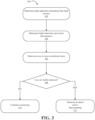
- FIG. 3 illustrates an exemplary process 300 of detecting an air bubble according to some embodiments of the disclosure.
- the process 300 may be performed, for example, using the optical sensor assembly 34 in the environment illustrated in FIG. 1 .
- light sources in the optical sensor assembly 34 are turned ON.
- the light intensities emanating from light emitters are determined.
- light emitters or light sources are the LED array 204.
- Light intensity of an LED in the LED array 204 is directly proportional to electrical current flowing through the LED.
- the processor 216 controls the LED current driver 202, which provides electrical current to the LED array 204, thereby controlling the light intensity of LEDs in the LED array 204.
- the processor 216 knows the current provided to an LED by the LED current driver 202 (which corresponds to the output intensity for the LED). For example, if two LEDs are in the LED array 204, with a first LED operating in the red light wavelength and the second LED operating in the infrared wavelength, the processor 216 determines the current provided to the first LED ( i emit,A ) and the current provided to the second LED ( i emit,B ).
- the light intensities detected at the photosensors are determined.
- a photosensor may generate a current proportional to an intensity of light incident upon the photosensor.
- two photosensors are provided: a first photosensor (sensitive to light in the red light wavelength) and a second photosensor (sensitive to light in the infrared wavelength). After the light emanating from each of the first LED and the second LED travels through the blood flow path 206, the intensity of the light in each wavelength is changed. The light received at the first photosensor and the second photosensor causes a current proportional to the light intensity to be generated at each respective photosensor.
- the first photosensor is sensitive to red light wavelength and will generate current proportional to only red light wavelength received
- the second photosensor is sensitive to infrared wavelength and will generate current proportional to infrared wavelength received.
- the receiver 212 then processes each current generated by each photosensor.
- the receiver 212 may have multiple channels to receive multiple currents from multiple photosensors detecting light at different wavelengths.
- the processor 216 receives from the receiver 212 a value for the current detected at the first photosensor ( i detect,A ) and a value for the current detected at the second photosensor ( i detect,B ).
- one or more normalized ratios are determined from light intensities absorbed in the blood flow path 206. That is, the normalized ratios are determined using the emanating light intensities obtained at step 302 and the received light intensities measured at step 304.
- the processor 216 determines a normalized ratio R using i emit,A , i emit,B , i detect,A , and i detect,B . Determining the normalized ratio R involves first subtracting i detect,A from i emit,A and subtracting i detect,B from i emit,B to obtain current differences i A and i B , respectively.
- the current differences i A and i B are proportional the light intensities of red light wavelength and infrared wavelength, respectively, that are absorbed in the blood flow path 206.
- the normalized ratio R then equals i A / i B .
- Step 308 the processor 216 or a measurement system, for example, controller 35 determines whether an air bubble is detected.
- Step 308 involves comparing historical values of the normalized ratio R to determine a change in the normalized ratio R .
- steps 302, 304, and 306 were performed at a previous time, and a normalized ratio R prev was stored in a non-transitory computer readable medium accessible by the measurement system.
- the measurement system determines the change in the normalized ratios R and R prev , normalized ratios at the current time period and the previous time period, respectively. If the change from a previous time period to a next time period meets or exceeds a predetermined threshold, the measurement system determines that an air bubble is detected.
- the system may then take an appropriate action at step 312 in response to detecting an air bubble, such as generating an alarm or stopping the pumping operation.
- the alarm may include, for example, an auditory alert generated at the controller 35, a visual alert such as a message or graphic displayed at the controller 35 or some other measurement system, or other forms of auditory, visual, data logging, and/or haptic notifications.
- the measurement system may automatically stop a pump, for example, the peristaltic pump 20 associated with pumping blood from the patient 10 through the dialyzer 22.
- the measurement system continues monitoring the normalized ratios at step 310 by performing steps 302, 304, and 306 to obtain a new normalized ratio for comparison at step 308.
- the detection of an air bubble at step 308 may indicate a degassing of blood-i.e., that the blood is under extreme negative pressure. Negative pressure signifies that there is an occlusion or collapse in the blood flow path, and continuing to pump under these conditions generates more negative pressure and may cause further complications. Thus, it is advantageous in certain situations to stop the pump when an air bubble is detected.
- embodiments of the disclosure provide a system that detects when an artery wall collapses and alerts caregivers so they may reduce the flowrate of the peristaltic pump 20 to match a patient's artery compliance.
- a needle being lodged against the arterial wall causes an air bubble
- stopping the pump gives a caregiver the chance to adjust the needle and restart the pulling of blood from the patient.
- the needle being lodged against the arterial wall blocks the blood flow path, thus creating negative pressure that may result in the creation of air bubbles.
- Process 300 involves monitoring the rate of change of the normalized ratio R over time. This may be accomplished using a predefined sampling rate, for example, a sampling rate between 100Hz and 1000Hz. Thus, a normalized ratio R is determined at specific times, and the receiver 212 can sample the current generated at the photosensors at the specified sampling rate. In this configuration, there is no need to turn the LED array 204 ON and OFF during measurements.
- medium absorbance e.g., absorbance of blood
- the medium absorbance may be written as f(R 1 , R 2 , R 3 ). Linear regression methods may be used to define the characteristic of the function f.
- absorbances I A , I B , I C can provide three ratios I A /I B , I A /I C or I B /I C .
- the process for detecting an air bubble using three wavelengths is similar to that for two wavelengths, except that more permutations of comparisons are possible. Potential advantages to having more than two wavelengths include: (1) different ratio results may reveal additional information, or (2) one ratio's results may be used to confirm another ratio's results. Also, using more than two wavelengths and obtaining more than one ratio provides the ability to adjudicate confusing or mixed results.
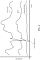
- FIG. 4 illustrates example waveforms showing absorbance characteristics and a ratio of the absorbances.
- Absorbance detected by an infrared sensor is shown compared to absorbance detected by a red wavelength sensor, and the ratio of the absorbances is obtained by dividing the absorbance detected by the infrared sensor by that detected by the red wavelength sensor.
- the absorbance characteristics plotted in FIG. 4 are sample measurements that may be obtained while monitoring a tubing with different transients due to a change in the medium contained in the tubing. As shown in FIG. 4 , as the medium changes, the absorbance characteristics change accordingly, thus the red wavelength sensor and the infrared sensor have a similar shape with different amplitudes. The differing amplitudes suggest that one wavelength is absorbed more by the medium and tubing properties than the other wavelength.
- the effect of common mode is removed when looking at the ratio of the absorbances.
- the ratio of the absorbances is mostly flat and non-varying compared to each absorbance characteristic used to determine the ratio. Effects of the color of the medium within the tubing or slowly varying color of the tubing are effectively removed when looking at the ratio. Thus, the ratio does not vary as much when compared to each of the absorbance characteristics.
- the rate of change of the ratio can be used to detect fast transients as shown in FIG. 4 .
- Fast transients are indicative of the presence of an air bubble.
- By taking the ratio of absorbances slowly varying effects are muted, but fast transients will be captured and will be easily distinguished.
- the fast transients corresponding to the present of an air bubble can clearly be seen when looking at the ratio of the absorbances over time.
Landscapes
- Health & Medical Sciences (AREA)
- Life Sciences & Earth Sciences (AREA)
- Engineering & Computer Science (AREA)
- Biomedical Technology (AREA)
- Hematology (AREA)
- Physics & Mathematics (AREA)
- Chemical & Material Sciences (AREA)
- General Health & Medical Sciences (AREA)
- Heart & Thoracic Surgery (AREA)
- Vascular Medicine (AREA)
- Biochemistry (AREA)
- General Physics & Mathematics (AREA)
- Pathology (AREA)
- Analytical Chemistry (AREA)
- Immunology (AREA)
- Cardiology (AREA)
- Anesthesiology (AREA)
- Urology & Nephrology (AREA)
- Medicinal Chemistry (AREA)
- Food Science & Technology (AREA)
- Biophysics (AREA)
- Ecology (AREA)
- Molecular Biology (AREA)
- Animal Behavior & Ethology (AREA)
- Public Health (AREA)
- Veterinary Medicine (AREA)
- External Artificial Organs (AREA)
- Measurement Of The Respiration, Hearing Ability, Form, And Blood Characteristics Of Living Organisms (AREA)
- Spectroscopy & Molecular Physics (AREA)
- Investigating Or Analysing Materials By Optical Means (AREA)
Description
- Patients with kidney failure or partial kidney failure typically undergo hemodialysis treatment, often at a hemodialysis treatment center or clinic. When healthy, kidneys maintain the body's internal equilibrium of water and minerals (e.g., sodium, potassium, chloride, calcium, phosphorous, magnesium, and sulfate). The kidneys also function as part of the endocrine system to produce the hormone erythropoietin as well as other hormones. Hemodialysis is an imperfect treatment to replace kidney function, in part, because it does not correct the endocrine functions of the kidney.
- In hemodialysis, blood is taken from a patient through an intake needle (or catheter) which draws blood from an artery located in a specific accepted access location (arm, thigh, subclavian, etc.). The drawn blood is pumped through extracorporeal tubing via a peristaltic pump, and then through a dialyzer which removes unwanted toxins such as blood urea, nitrogen, potassium, and excess water from the blood. As the blood passes through the dialyzer, it travels in straw-like tubes which serve as semi-permeable membrane passageways for the uncleaned blood. Fresh dialysate liquid, which is a solution of chemicals and water, flows through the dialyzer in the direction opposite the blood flow. As the dialysate flows through the dialyzer, it surrounds the straw-like membranes in the dialyzer. The fresh dialysate collects excess impurities passing through the straw-like tubes by diffusion, and also collects excess water through an ultrafiltration process due to a pressure drop across the membranes. The used dialysate exits the dialyzer with the excess fluids and toxins via an output tube, thus cleansing the blood flowing through the dialyzer. The dialyzed blood then flows out of the dialyzer via tubing and a needle (or catheter) back into the patient. Sometimes, a heparin drip or pump is provided along the extracorporeal blood flow loop in order to prevent clotting during the hemodialysis process. Several liters of excess fluid can be removed during a typical multi-hour treatment session. In the U.S., a chronic patient will normally undergo hemodialysis treatment in a dialysis center three times per week, either on Monday-Wednesday-Friday schedule or a Tuesday-Thursday-Saturday schedule.
- Hemodialysis has an acute impact on the fluid balance of the body due in part to the rapid change in circulating blood volume. When the fluid removal rate is more rapid than the plasma refilling rate of the body, intravascular blood volume decreases. The resulting imbalance has been linked to complications such as hypotension, loss of consciousness, headaches, vomiting, dizziness and cramps experienced by the patient, both during and after dialysis treatments. Continuous quantitative measurement of parameters relating to the circulating blood volume (in real-time) during hemodialysis reduces the chance of dialysisinduced hypotension, and otherwise optimizes dialysis therapy regimes by controlling fluid balance and aiding in achieving the appropriate dry weight for the patient.
US 2012/0095306 A1 andUS 5,589,935 A are referred to as prior art.US 2012/0095306 describes a method of detecting gas bubbles in a living body, comprising: transmitting at least one original electromagnetic signal to a body portion; detecting a signal modulated by a flow of blood in said body portion; and analyzing a perturbation in said signal to determine at least one of an existence and a property of a bubble in said blood flow. - One embodiment of the disclosure provides a method according to
claim 1. - Another embodiment of the disclosure provides a system according to claim 8.
- Yet another embodiment of the disclosure provides a non-transitory computer-readable medium having processor-executable instructions according to claim 12. Optional features are mentioned in the dependent claims 2-7,9-11 and 13-14.
-
-
FIG. 1 is a perspective view of a typical patient undergoing hemodialysis treatment with a non-invasive, optical blood monitor monitoring the patient's blood in real-time as it passes through extracorporeal tubing in the hemodialysis system; -
FIG. 2 illustrates an exemplary system for measuring blood constituents according to some embodiments of the disclosure; -
FIG. 2A illustrates another exemplary system for measuring blood constituents according to some embodiments of the disclosure; -
FIG. 3 illustrates a process of detecting an air bubble according to some embodiments of the disclosure; and -
FIG. 4 illustrates example waveforms showing absorbance characteristics and a ratio of the absorbances. - In a renal dialysis treatment session, occlusion of an arterial blood access line due to blood flow at high flow rates (300-500 ml/min) may result in very low negative pressures (< 200 mmHg) which would result in degassing of the blood. As such, air bubble detection is important for indicating whether an arterial occlusion has occurred. One way of optically detecting air bubbles is with a single light intensity wavelength. The optical air bubble detection on the arterial line can thus be used for indicating an arterial occlusion event and alarming a user. While optical air bubble detection is desirable, and can be achieved with a single light intensity wavelength, it is affected by several factors affecting the single light wavelength absorbance.
- Single light wavelength absorbance is affected by the color of the medium or blood, which varies significantly based on the blood hematocrit concentration and oxygenation level. Single light wavelength is also affected by sensor to sensor variability across multiple sensors. A sensor includes a single wavelength source or emitter and a single wavelength detector. Sensor to sensor variability may be reduced through a self-normalization step where sensor measurements are normalized relative to a baseline of its measurement. For example, an empty tubing may be used with a sensor to characterize the sensor's profile while adjusting light input to the sensor. This self-normalization or sensor calibration can be performed on each source-detector combination to ensure signal integrity and sensor response at wavelength of interest.
- Also during dialysis, the disposable tubing that contains blood and through which the optical detection is taking place undergoes discoloration and loses some of its transparency over time, thus affecting measurements relying on single light wavelength absorbance. Other factors affecting single light wavelength absorbance include transient effects during dialysis. For example, when a saline solution dose is introduced and mixes with blood, the blood becomes diluted the color of the medium contained in the tubing lightens. Furthermore, when the saline delivery ends, and blood returns to the tubing mixing with saline currently in the tubing, the color of the medium contained in the tubing darkens.
- Saline delivery is typically clinically introduced during dialysis treatment in order to deliver medications to the patient, or in the case of a patient suffering from hypovolemia, saline is introduced to allow for rapid patient recovery. Such variability in factors affecting the absolute intensity of light absorption makes the detection of air based purely on intensity level of light of a single wavelength challenging and difficult to adapt with the various factors. Using a single wavelength, an optical sensor typically interprets detection of blood when the single wavelength light is mostly absorbed (or equivalently reduced transmission of light), thus resulting in a low-range sensor output. Using a single wavelength, the presence of air in the tubing produces scattering, which also reduces transmission, but not as much as blood, and thus resulting in a mid-range sensor output. Using a single wavelength, the presence of clear water or saline in the tubing results in focused transmission with little absorbance of the single wavelength light, thus resulting in a high-range sensor output. A single wavelength optical sensor may then be used to obtain "typical" levels of sensor outputs for blood, air, and saline in order to interpret contents of the tubing during dialysis.
- Embodiments of the disclosure provide an improved methodology for detection of a transient air bubble by removing one or more effects of common mode factors affecting the absorbance of the light, such as, medium color, tubing color, angle of illumination, or temperature of the optical detector. The methodology involves using a normalized ratio (R) of the absorbance intensity of two light wavelengths through the medium. By using the normalized ratio R, common factors affecting the absolute scale of light intensity are eliminated. Only factors affecting the wavelengths differently result in a change to the value and sensitivity of the normalized ratio R. When taking a ratio, their effects cancel out.
-
FIG. 1 is a perspective view of a typical patient undergoing hemodialysis treatment with a non-invasive, optical blood monitor monitoring the patient's blood in real-time as it passes through extracorporeal tubing in the hemodialysis system. The environment illustrated inFIG. 1 is usable with exemplary embodiments of the present disclosure. Further, it will be appreciated that the environment shown inFIG. 1 is merely exemplary, and that the principles discussed herein with respect to exemplary embodiments of the present disclosure may be implemented in other environments as well. -
FIG. 1 illustrates apatient 10 undergoing hemodialysis treatment using a conventional hemodialysis system 12, as well as a non-invasive, optical blood monitor 14. A typical hemodialysis clinic will have several hemodialysis systems 12 for treating patients on a Monday-Wednesday-Friday schedule or a Tuesday-Thursday-Saturday schedule. While the invention is not limited to the number of hemodialysis systems located at a clinic, or the specific type of hemodialysis system, the general operation of the hemodialysis system 12 is helpful for understanding the environment in which the invention is intended to operate. - An input needle or catheter 16 is inserted into an access site of the
patient 10, such as in the arm, and is connected toextracorporeal tubing 18 that leads to a peristaltic pump 20 and then to a dialyzer or blood filter 22. The dialyzer 22 removes toxins and excess fluid from the patient's blood. The dialyzed blood is returned from the dialyzer 22 throughextracorporeal tubing 24 and return needle or catheter 26. In some parts of the world, the extracorporeal blood flow may additionally receive a heparin drip to prevent clotting. The excess fluids and toxins are removed by clean dialysate liquid which is supplied to the dialyzer 22 via tube 28 and removed for disposal viatube 30. A typical hemodialysis treatment session takes about 3 to 5 hours in the United States. - In the exemplary environment depicted in
FIG. 1 , the optical blood monitor 14 includes a blood chamber 32, an opticalblood sensor assembly 34, and acontroller 35. The blood chamber 32 is preferably located in line with theextracorporeal tubing 18 upstream of the dialyzer 22. Blood from the peristaltic pump 20 flows through thetubing 18 into the blood chamber 32. Thepreferred sensor assembly 34 includes LED photo emitters that emit light at optical wavelengths. The blood chamber 32 includes lenses so that the emitters and detectors of thesensor assembly 34 can view the blood flowing through the blood chamber 32, and determine whether a transient air bubble is detected in the blood. - In another exemplary environment, the optical blood monitor includes an optical blood sensor assembly and a controller and does not include a blood chamber. The optical blood sensor assembly clasps onto the extracorporeal tubing upstream of the dialyzer. The blood sensor assembly includes LED photo emitters that emit light in optical wavelengths including red light, infrared light, ultraviolet light, blue light, green light, and/or any wavelength in the optical spectrum. The emitted light travels from the LED photo emitters through the extracorporeal tubing to light detectors (e.g. photodiodes) also included in the optical blood sensor assembly.
-
FIG. 2 illustrates anexemplary system 200 that may be used to measure blood constituents using an optical blood sensor assembly according to some embodiments of the disclosure. An LEDcurrent driver 202 produces multiple currents to drive anLED array 204. TheLED array 204 contains LED1 to LEDN. Each LED in theLED array 204 operates at a different wavelength, and the LEDcurrent driver 202 is configured to provide power to turn ON or turn OFF each LED in theLED array 204. -
FIG. 2 shows thatprocessor 216 controls the LEDcurrent driver 202, so in some embodiments, theprocessor 216 may determine which LEDs should be turned ON at a certain time during measurement. Light from theLED array 204 is incident on ablood container 208, passes through ablood flow path 206, and is detected at a photosensor 210 (or "photodetector") which may be a photodiode. Theblood container 208 may be, for example, a blood chamber 32 located in line with anextracorporeal tubing 18, or may be, for example, theextracorporeal tubing 18 itself. Thephotosensor 210 may be one or more photosensors sensitive to wavelengths emitted by theLED array 204. Thephotosensor 210 collects and integrates detected LED light and generates a current. The current is then amplified and filtered by thereceiver 212. Thereceiver 212 may also convert the amplified and filtered current from an analog signal to a digital signal, providing the digital signal to theprocessor 216 for further analysis. - The
processor 216 is designed to interface with other electronic components allowing input and output communication of signals to and from the optical blood sensor assembly. For example, apart from theblood container 208 including theblood path 206, every other component identified insystem 200 may be part of a optical blood sensor assembly, for example, an opticalblood sensor assembly 34 as depicted inFIG. 1 . Using the embodiment inFIG. 1 , the opticalblood sensor assembly 34 may communicate with acontroller 35 for displaying system outputs and/or receiving command signals or calibration signals. - In some embodiments, the
processor 216 performs calculations and analyses based on the digital signal received from thereceiver 212 and determines whether air bubbles are present in theblood flow path 206. In other embodiments, theprocessor 216 may provide the digital signal received from thereceiver 212 to an external computing device using the input/output communication channels so that the external computing device, for example,controller 35, determines whether air bubbles are present in theblood flow path 206.Processor 216 may be a microprocessor, a microcontroller, a field programmable gate array (FPGA), a complex programmable logic device (CPLD), an application specific integrated circuit (ASIC), etc. -
FIG. 2A illustrates anotherexemplary system 201 that may be used to measure blood constituents using an optical blood sensor assembly according to some embodiments of the disclosure. Thesystem 201 includes aprocessor 217, LEDcurrent driver 203, amulti-wavelength LED 205, ablood flow path 207, atubing 209, awideband photosensor 211, and a receiver/signal processor 213. Themulti-wavelength LED 205 may generate more than one wavelength, and thewideband photosensor 211 is sensitive to the more than one wavelength generated by themulti-wavelength LED 205. The receiver/signal processor 213 is configured to obtain a current from thephotosensor 211 and separate the magnitude of the current contributions of the different wavelengths sensed by thewideband photosensor 211. The receiver/signal processor 213 may separate the current contributions from the different wavelengths using digital and/or analog signal processing. The receiver/signal processor 213 then provides the separated current contributions to theprocessor 217. - The exemplary systems depicted in
FIG. 2 andFIG. 2A may be used for detection of air bubbles by continuous monitoring of a blood flow path. The Beer-Lambert law defines the concentration ci of an absorbent in solution to be determined by the intensity of light transmitted through the solution, knowing the path length d λ , the intensity of the incident light I0,λ , and the extinction coefficient ε i,λ at a particular wavelength λ. In generalized from, the Beer-Lambert law is expressed as Eq. (1):

- The detected absorbance of a first light wavelength's intensity, called IA, is divided by the detected absorbance of a second light wavelength's intensity, called IB, thus producing a ratio of R=IA/IB, which represents the normalized ratio R of Beer-Lambert's light intensity at wavelength A over the Beer-Lambert light intensity at wavelength B. Note that IA and IB represent detected absorbance parameters. Detected absorbance is defined as light intensity absorbed by absorbents in the medium or solution as defined in the Beer-Lambert law. The detected absorbance is obtained through a source-detector measurement system by subtracting the light intensity received at the detector from the light intensity provided at the source. For example, in
FIG. 2 ,LED 1 inLED array 204 emits 810 nm wavelength light with intensity Iemit,810nm, and the light travels through theblood flow path 206 and is incident on one photosensor inphotosensor 210. Theprocessor 216 determines the light intensity to be Idetect,810nm. The detected absorbance I810nm is determined as Iemit,810nm - Idetect,810nm. - The ratio R=IA/IB normalizes all common components affecting the plurality of light wavelengths' absorbance intensity. The ratio R will therefore be limited in its sensitivity to the actual factors distinctly affecting the light wavelengths individually as opposed to common factors affecting all wavelengths' intensities. Such normalization methods are effective in limiting the sensitivity of the detection ratios to the transient factors, such as, air bubble presence.
- During dialysis, the color of the medium in the tubing, for example, the
extracorporeal tubing 18, presents itself as a persistent value to the absorbance variable that is slowly varying. For example, the color of the medium when changing from blood to saline and back to blood will take on a gradual, slowly changing transient characteristic with an intermediary that is a mixture of both saline and blood. When air bubbles are present, however, a rapid variation occurs in the measured absorbance of the medium. Therefore, in some embodiments, a variance of the measured absorbance in theblood flow path 206 may be used to detect the presence of air bubbles. Embodiments of the disclosure thus provide an ability to avoid false alarms due to gradual changes in color of the medium (blood or saline or mixture thereof) caused by slow-varying transitions in the respective concentrations of blood and saline. Blood tubing color changes are also eliminated since these color changes are also slowly varying compared to air bubble presence. As such, the system is more robust and reliable for air bubble detection for arterial occlusion indication. - Due to the transient nature of the composition of the medium, a sampling rate may be defined for the measurement system of
FIGS. 1 ,2 and2A . For example, theoptical sensor assembly 34 may make measurements with a sampling rate varying from 100 Hz to 1000 Hz. The sampling rate should be fast enough to realize fast passing transient bubble events under flowing fluid conditions. - In an exemplary embodiment, the
optical sensor assembly 34 includes an LED that emits light in a red light wavelength, an LED that emits light in an infrared wavelength, a photosensor sensitive to red light wavelengths, and a photosensor sensitive to infrared wavelengths. Since the photosensors are sensitive to specific wavelength regimes, the LED-photosensor pairs for the red light wavelength and the infrared wavelength are operated at the same time to obtain measurements. That is, both LEDs are ON at the same time, and both photosensors are receptive at the same time to obtain simultaneous measurements at the red light wavelength and the infrared wavelength. A normalized ratio is then determined based on the measurements. -
FIG. 3 illustrates anexemplary process 300 of detecting an air bubble according to some embodiments of the disclosure. Theprocess 300 may be performed, for example, using theoptical sensor assembly 34 in the environment illustrated inFIG. 1 . In the setup ofFIG. 1 , light sources in theoptical sensor assembly 34 are turned ON. Atstep 302, the light intensities emanating from light emitters are determined. Using the illustration inFIG. 2 , light emitters or light sources are theLED array 204. Light intensity of an LED in theLED array 204 is directly proportional to electrical current flowing through the LED. Theprocessor 216 controls the LEDcurrent driver 202, which provides electrical current to theLED array 204, thereby controlling the light intensity of LEDs in theLED array 204. As such, atstep 302, theprocessor 216 knows the current provided to an LED by the LED current driver 202 (which corresponds to the output intensity for the LED). For example, if two LEDs are in theLED array 204, with a first LED operating in the red light wavelength and the second LED operating in the infrared wavelength, theprocessor 216 determines the current provided to the first LED (iemit,A ) and the current provided to the second LED (iemit,B ). - At
step 304, the light intensities detected at the photosensors are determined. A photosensor may generate a current proportional to an intensity of light incident upon the photosensor. For example, in accordance withFIG. 2 , two photosensors are provided: a first photosensor (sensitive to light in the red light wavelength) and a second photosensor (sensitive to light in the infrared wavelength). After the light emanating from each of the first LED and the second LED travels through theblood flow path 206, the intensity of the light in each wavelength is changed. The light received at the first photosensor and the second photosensor causes a current proportional to the light intensity to be generated at each respective photosensor. Note that the first photosensor is sensitive to red light wavelength and will generate current proportional to only red light wavelength received, and the second photosensor is sensitive to infrared wavelength and will generate current proportional to infrared wavelength received. Thereceiver 212 then processes each current generated by each photosensor. Thereceiver 212 may have multiple channels to receive multiple currents from multiple photosensors detecting light at different wavelengths. Theprocessor 216 receives from the receiver 212 a value for the current detected at the first photosensor (idetect,A ) and a value for the current detected at the second photosensor (idetect,B ). - At
step 306, one or more normalized ratios are determined from light intensities absorbed in theblood flow path 206. That is, the normalized ratios are determined using the emanating light intensities obtained atstep 302 and the received light intensities measured atstep 304. For example, in accordance withFIG. 2 , theprocessor 216 determines a normalized ratio R using iemit,A, iemit,B, idetect,A, and idetect,B, Determining the normalized ratio R involves first subtracting idetect,A from iemit,A and subtracting idetect,B from iemit,B to obtain current differences iA and iB, respectively. The current differences iA and iB are proportional the light intensities of red light wavelength and infrared wavelength, respectively, that are absorbed in theblood flow path 206. The normalized ratio R then equals iA /iB. - At
step 308, theprocessor 216 or a measurement system, for example,controller 35 determines whether an air bubble is detected. Step 308 involves comparing historical values of the normalized ratio R to determine a change in the normalized ratio R. For example, steps 302, 304, and 306 were performed at a previous time, and a normalized ratio Rprev was stored in a non-transitory computer readable medium accessible by the measurement system. The measurement system then determines the change in the normalized ratios R and Rprev, normalized ratios at the current time period and the previous time period, respectively. If the change from a previous time period to a next time period meets or exceeds a predetermined threshold, the measurement system determines that an air bubble is detected. The system may then take an appropriate action atstep 312 in response to detecting an air bubble, such as generating an alarm or stopping the pumping operation. The alarm may include, for example, an auditory alert generated at thecontroller 35, a visual alert such as a message or graphic displayed at thecontroller 35 or some other measurement system, or other forms of auditory, visual, data logging, and/or haptic notifications. Additionally or alternatively, the measurement system may automatically stop a pump, for example, the peristaltic pump 20 associated with pumping blood from the patient 10 through the dialyzer 22. - If the change from the previous time period to the next time period is below the predetermined threshold, the measurement system continues monitoring the normalized ratios at
step 310 by performingsteps step 308. - The detection of an air bubble at
step 308 may indicate a degassing of blood-i.e., that the blood is under extreme negative pressure. Negative pressure signifies that there is an occlusion or collapse in the blood flow path, and continuing to pump under these conditions generates more negative pressure and may cause further complications. Thus, it is advantageous in certain situations to stop the pump when an air bubble is detected. - For example, if an arterial wall collapse causes an air bubble, stopping the pump gives a caregiver time for the artery walls to expand before resuming operation at a slower flowrate. In some cases, the caregiver may gradually increase or ramp up the flowrate from the slower flowrate to a higher flowrate. Different patients come with different artery compliances, and attempting to pull blood from a collapsed artery will not result in blood being pulled. Thus, embodiments of the disclosure provide a system that detects when an artery wall collapses and alerts caregivers so they may reduce the flowrate of the peristaltic pump 20 to match a patient's artery compliance.
- In another example, if a needle being lodged against the arterial wall causes an air bubble, stopping the pump gives a caregiver the chance to adjust the needle and restart the pulling of blood from the patient. The needle being lodged against the arterial wall blocks the blood flow path, thus creating negative pressure that may result in the creation of air bubbles.
- In yet another example, if a kink in tubing causes an air bubble, stopping the pump gives a caregiver the chance to adjust the tubing and restart the pulling of blood from the patient.
-
Process 300 involves monitoring the rate of change of the normalized ratio R over time. This may be accomplished using a predefined sampling rate, for example, a sampling rate between 100Hz and 1000Hz. Thus, a normalized ratio R is determined at specific times, and thereceiver 212 can sample the current generated at the photosensors at the specified sampling rate. In this configuration, there is no need to turn theLED array 204 ON and OFF during measurements. - In another embodiment, more than two wavelengths may be used. For example, if a third wavelength is introduced, then the system may obtain further ratios across the three wavelengths, including, R1=IA/IB, R2=IA/IC, R3=IB/IC. When more than two ratios are used, medium absorbance (e.g., absorbance of blood) will be a function of the multiple ratios. For example, in an embodiment with three ratios R1, R2, and R3, the medium absorbance may be written as f(R1, R2, R3). Linear regression methods may be used to define the characteristic of the function f.
- In the case where three wavelengths are used, absorbances IA, IB, IC can provide three ratios IA/IB, IA/IC or IB/IC. The process for detecting an air bubble using three wavelengths is similar to that for two wavelengths, except that more permutations of comparisons are possible. Potential advantages to having more than two wavelengths include: (1) different ratio results may reveal additional information, or (2) one ratio's results may be used to confirm another ratio's results. Also, using more than two wavelengths and obtaining more than one ratio provides the ability to adjudicate confusing or mixed results. For example, in the case where three wavelengths are used, if historical values of R1 show an air bubble is present while historical values of R2 and R3 show that no air bubble is present, then the measurement system may not generate an alarm since two ratios out of three indicate no air bubble. Thus, the use of more than two wavelengths may yield more robust true positives.
-
FIG. 4 illustrates example waveforms showing absorbance characteristics and a ratio of the absorbances. Absorbance detected by an infrared sensor is shown compared to absorbance detected by a red wavelength sensor, and the ratio of the absorbances is obtained by dividing the absorbance detected by the infrared sensor by that detected by the red wavelength sensor. The absorbance characteristics plotted inFIG. 4 are sample measurements that may be obtained while monitoring a tubing with different transients due to a change in the medium contained in the tubing. As shown inFIG. 4 , as the medium changes, the absorbance characteristics change accordingly, thus the red wavelength sensor and the infrared sensor have a similar shape with different amplitudes. The differing amplitudes suggest that one wavelength is absorbed more by the medium and tubing properties than the other wavelength. - The effect of common mode is removed when looking at the ratio of the absorbances. The ratio of the absorbances is mostly flat and non-varying compared to each absorbance characteristic used to determine the ratio. Effects of the color of the medium within the tubing or slowly varying color of the tubing are effectively removed when looking at the ratio. Thus, the ratio does not vary as much when compared to each of the absorbance characteristics.
- The rate of change of the ratio can be used to detect fast transients as shown in
FIG. 4 . Fast transients are indicative of the presence of an air bubble. By taking the ratio of absorbances, slowly varying effects are muted, but fast transients will be captured and will be easily distinguished. Thus, as can be seen inFIG. 4 , the fast transients corresponding to the present of an air bubble can clearly be seen when looking at the ratio of the absorbances over time. - The use of the terms "a" and "an" and "the" and "at least one" and similar referents in the context of describing the invention (especially in the context of the following claims) are to be construed to cover both the singular and the plural, unless otherwise indicated herein or clearly contradicted by context. The use of the term "at least one" followed by a list of one or more items (for example, "at least one of A and B") is to be construed to mean one item selected from the listed items (A or B) or any combination of two or more of the listed items (A and B), unless otherwise indicated herein or clearly contradicted by context. The terms "comprising," "having," "including," and "containing" are to be construed as open-ended terms (i.e., meaning "including, but not limited to,") unless otherwise noted. Recitation of ranges of values herein are merely intended to serve as a shorthand method of referring individually to each separate value falling within the range, unless otherwise indicated herein, and each separate value is incorporated into the specification as if it were individually recited herein. All methods described herein can be performed in any suitable order unless otherwise indicated herein or otherwise clearly contradicted by context. The use of any and all examples, or exemplary language (e.g., "such as") provided herein, is intended merely to better illuminate the invention and does not pose a limitation on the scope of the invention unless otherwise claimed. No language in the specification should be construed as indicating any non-claimed element as essential to the practice of the invention.
- Preferred embodiments of this invention are described herein, including the best mode known to the inventors for carrying out the invention. Variations of those preferred embodiments may become apparent to those of ordinary skill in the art upon reading the foregoing description. The inventors expect skilled artisans to employ such variations as appropriate, and the inventors intend for the invention to be practiced otherwise than as specifically described herein. Accordingly, this invention includes all modifications of the subject matter recited in the claims appended hereto as permitted by applicable law.
Claims (14)
- A method for detecting air bubbles in a blood flow path (206, 207, 208, 209) using at least one light emitter (204, 205) to generate different wavelengths and at least one photosensor (210, 211), the method comprising:setting initial intensities of light at a first wavelength emanating from the at least one light emitter (204, 205) and of light at a second wavelength emanating from the at least one light emitter (204, 205);determining intensities of the light at the first wavelength and of the light at the second wavelength received at the at least one photosensor (210, 211), wherein the light at the first wavelength and the light at the second wavelength received at the at least one photosensor (210, 211) traverses the blood flow path (206, 207, 208, 209);determining a normalized ratio between an absorbance for the light at the first wavelength and an absorbance for the light at the second wavelength using the initial intensities of the light at the first wavelength and of the light at the second wavelength emanating from the at least one light emitter (204, 205) and the intensities of the light at the first wavelength and of the light at the second wavelength received at the at least one photosensor (210, 211), wherein the absorbance for the light at the first wavelength is obtained by subtracting the intensity of the light at the first wavelength at the at least one photosensor (210, 211) from the initial intensity of the light at the first wavelength emanating from the at least one light emitter (204, 205), and wherein the absorbance for the light at the second wavelength is obtained by subtracting the intensity of the light at the second wavelength at the at least one photosensor (210, 211) from the initial intensity of the light at the second wavelength emanating from the at least one light emitter (204, 205); anddetermining whether an air bubble is present in the blood flow path (206, 207, 208, 209) based on the determined normalized ratio by determining a change in the normalized ratio and a normalized ratio at a previous time period, wherein the air bubble is present if the change meets or exceeds a predetermined threshold.
- The method according to claim 1, further comprising:
generating an alarm in response to determining that an air bubble is present in the blood flow path (206, 207, 208, 209). - The method according to claim 1, wherein the at least one light emitter (204, 205) comprises at least one light emitting diode (LED) and the at least one photosensor (210, 211) comprises at least one photodiode.
- The method according to claim 3, wherein setting the initial intensities of the light at the first wavelength emanating from the at least one light emitter (204, 205) and of the light at the second wavelength emanating from the at least one light emitter (204, 205) comprises:
providing at least one electrical current at at least one predetermined current level to the at least one LED (204, 205). - The method according to claim 3, wherein determining the intensities of the light at the first wavelength and of the light at the second wavelength received at the at least one photosensor (210, 211) comprises:
receiving at least one electrical current from the at least one photodiode (210, 211), each electrical current being proportional to light intensity sensed by a respective photodiode (210, 211). - The method according to claim 3, wherein:the first and second wavelengths are generated by the LED (204, 205), the first and second wavelengths being a red light wavelength and an infrared wavelength; andthe normalized ratio is obtained by dividing an absorbance for the red light wavelength by an absorbance for the infrared wavelength.
- The method according to claim 1, wherein a sampling rate for determining whether an air bubble is present in the blood flow path (206, 207, 208, 209) is within the range of 100Hz to 1000Hz.
- A system for detecting air bubbles in a blood flow path (206, 207, 208, 209), the system comprising:at least one light emitter (204, 205) configured to generate different wavelengths;at least one photosensor (210, 211); anda processor (35, 216, 217), configured to:set initial intensities of light at a first wavelength emanating from the at least one light emitter (204, 205) and of light at a second wavelength emanating from the at least one light emitter (204, 205);determine intensities of the light at the first wavelength and of the light at the second wavelength received at the at least one photosensor (210, 211), wherein the light at the first wavelength and the light at the second wavelength received at the at least one photosensor (210, 211) traverses the blood flow path (206, 207, 208, 209);determine a normalized ratio between an absorbance for the light at the first wavelength and an absorbance for the light at the second wavelength using the initial intensities of the light at the first wavelength and of the light at the second wavelength emanating from the at least one light emitter (204, 205) and the intensities of the light at the first wavelength and of the light at the second wavelength received at the at least one photosensor (210, 211), wherein the absorbance for the light at the first wavelength is obtained by subtracting the intensity of the light at the first wavelength at the at least one photosensor (210, 211) from the initial intensity of the light at the first wavelength emanating from the at least one light emitter (204, 205), and wherein the absorbance for the light at the second wavelength is obtained by subtracting the intensity of the light at the second wavelength at the at least one photosensor (210, 211) from the initial intensity of the light at the second wavelength emanating from the at least one light emitter (204, 205); anddetermine whether an air bubble is present in the blood flow path (206, 207, 208, 209) based on the determined normalized ratio by determining a change in the normalized ratio and a normalized ratio at a previous time period, wherein the air bubble is present if the change meets or exceeds a predetermined threshold.
- The system according to claim 8, wherein the processor (35, 216, 217) is further configured to:
generate an alarm and/or stop a pumping operation in response to determining that an air bubble is present in the blood flow path (206, 207, 208, 209). - The system according to claim 8, wherein the system comprises one of the following:- the at least one light emitter (204, 205) comprises at least one light emitting diode (LED) and the at least one photosensor (210, 211) comprises at least one photodiode;- the at least one light emitter (204, 205) comprises at least one light emitting diode (LED) and the at least one photosensor (210, 211) comprises at least one photodiode, wherein the system further comprises at least one LED driver (202, 203) configured to provide electrical current at at least one predetermined current level to the at least one LED (204, 205);- the at least one light emitter (204, 205) comprises at least one light emitting diode (LED) and the at least one photosensor (210, 211) comprises at least one photodiode, wherein the processor (35, 216, 217) is further configured to determine intensities of the light at the first wavelength and of the light at the second wavelength received at the at least one photosensor (210, 211) based on at least one electrical current generated by the at least one photodiode (210, 211), each electrical current being proportional to light intensity sensed by a respective photodiode (210, 211);- the at least one light emitter (204, 205) comprises at least one light emitting diode (LED) and the at least one photosensor (210, 211) comprises at least one photodiode, wherein the first and second wavelengths are generated by the at least one LED (204, 205), the first and second wavelengths being a red light wavelength and an infrared wavelength; andthe normalized ratio is obtained by dividing an absorbance for the red light wavelength by an absorbance for the infrared wavelength.
- The system according to claim 8, wherein a sampling rate for determining whether an air bubble is present in the blood flow path (206, 207, 208, 209) is within the range of 100Hz to 1000Hz.
- A non-transitory computer-readable medium having processor-executable instructions which cause, when executed, the system of claim 8 to execute the steps of the method of claim 1.
- The non-transitory computer-readable medium according to claim 12,
wherein the processor-executable instructions, when executed, further facilitate:
generating an alarm and/or stopping a pumping operation in response to determining that an air bubble is present in the blood flow path (206, 207, 208, 209). - The non-transitory computer readable medium according to claim 12, wherein the at least one light emitter (204, 205) comprises at least one light emitting diode (LED) and the at least one photosensor (210, 211) comprises at least one photodiode.
Applications Claiming Priority (2)
| Application Number | Priority Date | Filing Date | Title |
|---|---|---|---|
| US15/483,495 US10576196B2 (en) | 2017-04-10 | 2017-04-10 | Optical detection of air bubbles in either saline or blood or a mixture of both |
| PCT/US2018/025666 WO2018191050A1 (en) | 2017-04-10 | 2018-04-02 | Optical detection of air bubbles in either saline or blood or a mixture of both |
Publications (3)
| Publication Number | Publication Date |
|---|---|
| EP3610258A1 EP3610258A1 (en) | 2020-02-19 |
| EP3610258A4 EP3610258A4 (en) | 2020-12-30 |
| EP3610258B1 true EP3610258B1 (en) | 2024-11-06 |
Family
ID=63710679
Family Applications (1)
| Application Number | Title | Priority Date | Filing Date |
|---|---|---|---|
| EP18785187.8A Active EP3610258B1 (en) | 2017-04-10 | 2018-04-02 | Optical detection of air bubbles in either saline or blood or a mixture of both |
Country Status (5)
| Country | Link |
|---|---|
| US (2) | US10576196B2 (en) |
| EP (1) | EP3610258B1 (en) |
| CN (1) | CN110494749B (en) |
| AU (1) | AU2018253025B2 (en) |
| WO (1) | WO2018191050A1 (en) |
Families Citing this family (13)
| Publication number | Priority date | Publication date | Assignee | Title |
|---|---|---|---|---|
| US12544498B2 (en) * | 2018-05-17 | 2026-02-10 | Gambro Lundia Ab | Treatment apparatus with gas separation device level controls and methods |
| US12059520B2 (en) * | 2019-04-08 | 2024-08-13 | Baxter International Inc. | Priming sensor for a medical fluid delivery system |
| CN110548179B (en) * | 2019-09-03 | 2021-10-19 | 苏州元禾医疗器械有限公司 | Method for monitoring seepage amount of wound exudate |
| IT202000006706A1 (en) * | 2020-03-31 | 2021-10-01 | Medica S P A | BLOOD FILTRATION MACHINE EQUIPPED WITH A MEASURING SYSTEM INCLUDING OPTICAL SENSORS |
| JP2023092286A (en) * | 2021-12-21 | 2023-07-03 | アズビル株式会社 | Concentration measuring device, concentration measuring system and concentration measuring method |
| CN114870125B (en) * | 2022-04-21 | 2026-03-03 | 健帆生物科技集团股份有限公司 | Pipeline structure installation prompting method, storage medium and blood purification equipment |
| CN119698549A (en) * | 2022-09-15 | 2025-03-25 | 美国西门子医学诊断股份有限公司 | Self-tuning bubble detector assembly, calibration method, and computer program product for a diagnostic analyzer |
| CN115575340B (en) * | 2022-11-08 | 2023-03-10 | 杭州谱育科技发展有限公司 | Absorbance detection device and method |
| LU103097B1 (en) | 2023-03-31 | 2024-10-03 | Stratec Se | Optical fluid verification for air bubble detection in fluid filled hoses |
| DE102023118626A1 (en) * | 2023-07-13 | 2025-01-16 | B.Braun Avitum Ag | Optical detection device for a fluid in a line section of a medical device |
| CN116942941B (en) * | 2023-09-14 | 2023-12-29 | 苏州森斯缔夫传感科技有限公司 | Light intensity comparison sensor, method and blood purifier |
| CN121191069B (en) * | 2025-11-21 | 2026-02-24 | 西安京工医疗科技有限公司 | ECMO pipeline blood flow state monitoring method and system based on video analysis |
| CN121558596B (en) * | 2026-01-21 | 2026-04-07 | 北京大学第三医院(北京大学第三临床医学院) | Blood HCT rapid detection system based on multispectral |
Family Cites Families (29)
| Publication number | Priority date | Publication date | Assignee | Title |
|---|---|---|---|---|
| JPS54131985A (en) * | 1978-04-05 | 1979-10-13 | Hitachi Ltd | Two-wavelength spectrophotometer |
| ATE80225T1 (en) * | 1989-05-23 | 1992-09-15 | Biosensors Technology Inc | METHOD OF DETERMINING SUBSTANCES IN ABSORBING AND SCATTERING MATRIX MATERIALS BY RADIATION ABSORPTION. |
| KR960016331B1 (en) * | 1990-08-29 | 1996-12-09 | 가부시끼가이샤 시마즈 세이사구쇼 | Absorbance detector |
| US5800361A (en) | 1995-02-06 | 1998-09-01 | Ntc Technology Inc. | Non-invasive estimation of arterial blood gases |
| CN1153463A (en) * | 1995-02-06 | 1997-07-02 | 丹尼尔B·雷伯恩 | Non-invasive measurement of arterial blood gases |
| US5589935A (en) | 1995-05-25 | 1996-12-31 | Honeywell, Inc. | Turbidity sensor with the capability of regulating the intensity of a light source |
| US6862534B2 (en) * | 2001-12-14 | 2005-03-01 | Optiscan Biomedical Corporation | Method of determining an analyte concentration in a sample from an absorption spectrum |
| US8055330B2 (en) | 2002-08-28 | 2011-11-08 | Noam Egozi | Sensing gas bubbles in a living body |
| US7671974B2 (en) * | 2003-10-29 | 2010-03-02 | Chf Solutions Inc. | Cuvette apparatus and system for measuring optical properties of a liquid such as blood |
| DE102005025515A1 (en) | 2005-06-03 | 2006-12-07 | Fresenius Medical Care Deutschland Gmbh | Method and apparatus for monitoring a flowing liquid for the presence of air |
| DE102005025500B3 (en) | 2005-06-03 | 2006-10-05 | Fresenius Medical Care Deutschland Gmbh | Monitoring presence of air in flowing liquid such as blood, by determining number of sequential time intervals in which amplitude of received ultrasound signal is less than reference level |
| US7661293B2 (en) * | 2007-02-06 | 2010-02-16 | Cosense, Inc. | Ultrasonic system for detecting and quantifying of air bubbles/particles in a flowing liquid |
| US8631683B2 (en) * | 2007-02-06 | 2014-01-21 | Fresenius Medical Care Holdings, Inc. | Dialysis systems including non-invasive multi-function sensor systems |
| US7661294B2 (en) | 2007-09-21 | 2010-02-16 | Cosense, Inc. | Non-invasive multi-function sensor system |
| US8403908B2 (en) | 2007-12-17 | 2013-03-26 | Hospira, Inc. | Differential pressure based flow sensor assembly for medication delivery monitoring and method of using the same |
| US8401604B2 (en) * | 2008-04-11 | 2013-03-19 | Glucovista, Llc | Apparatus and methods for non-invasive measurement of a substance within a body |
| CN101269246B (en) * | 2008-05-05 | 2011-10-12 | 重庆山外山科技有限公司 | Continuous blood cleaning equipment with replacement liquid purifier |
| US8130369B2 (en) | 2008-11-05 | 2012-03-06 | Fresenius Medical Care Holdings, Inc. | Measuring hematocrit and estimating hemoglobin values with a non-invasive, optical blood monitoring system |
| DE102009017304A1 (en) | 2009-04-11 | 2010-10-21 | Fresenius Medical Care Deutschland Gmbh | Apparatus and method for measuring a blood component in blood for an extracorporeal blood treatment device |
| DE102010034553A1 (en) * | 2010-08-17 | 2012-03-08 | Fresenius Medical Care Deutschland Gmbh | Device for determining and / or monitoring foreign structures in a fluid or a fluid stream and method for this purpose |
| US9194792B2 (en) | 2010-09-07 | 2015-11-24 | Fresenius Medical Care Holdings, Inc. | Blood chamber for an optical blood monitoring system |
| US9173988B2 (en) * | 2010-11-17 | 2015-11-03 | Fresenius Medical Care Holdings, Inc. | Sensor clip assembly for an optical monitoring system |
| JP5940099B2 (en) * | 2011-02-25 | 2016-06-29 | フレセニウス メディカル ケア ホールディングス インコーポレーテッド | Shroud-covered sensor clip assembly and blood chamber for optical blood monitoring systems |
| US8836519B2 (en) | 2011-05-12 | 2014-09-16 | Fresenius Medical Care Holdings, Inc. | Determining the absence or presence of fluid in a dialysis system |
| JP5816014B2 (en) * | 2011-07-14 | 2015-11-17 | 旭化成メディカル株式会社 | Plasma purification apparatus and method of operating plasma purification apparatus |
| EP2836122A4 (en) * | 2012-04-09 | 2016-03-16 | Mec Dynamics Corp | Measurement of total hemoglobin in whole blood |
| KR102189845B1 (en) | 2014-06-03 | 2020-12-14 | 한국전자통신연구원 | Apparatus and method for measuring properties of fluids |
| CN205729374U (en) * | 2016-05-24 | 2016-11-30 | 重庆医科大学附属儿童医院 | A kind of baby's blood oxygen saturation instrument |
| CN106178157A (en) * | 2016-06-28 | 2016-12-07 | 广东宝莱特医用科技股份有限公司 | Blood detection and the method for bubble detection during a kind of hemodialysis |
-
2017
- 2017-04-10 US US15/483,495 patent/US10576196B2/en active Active
-
2018
- 2018-04-02 AU AU2018253025A patent/AU2018253025B2/en active Active
- 2018-04-02 CN CN201880024353.1A patent/CN110494749B/en active Active
- 2018-04-02 EP EP18785187.8A patent/EP3610258B1/en active Active
- 2018-04-02 WO PCT/US2018/025666 patent/WO2018191050A1/en not_active Ceased
-
2020
- 2020-01-22 US US16/749,940 patent/US11083832B2/en active Active
Also Published As
| Publication number | Publication date |
|---|---|
| US11083832B2 (en) | 2021-08-10 |
| CN110494749A (en) | 2019-11-22 |
| EP3610258A4 (en) | 2020-12-30 |
| CA3058184A1 (en) | 2018-10-18 |
| US20200155749A1 (en) | 2020-05-21 |
| WO2018191050A1 (en) | 2018-10-18 |
| AU2018253025B2 (en) | 2024-07-11 |
| US10576196B2 (en) | 2020-03-03 |
| CN110494749B (en) | 2021-06-22 |
| AU2018253025A1 (en) | 2019-10-03 |
| EP3610258A1 (en) | 2020-02-19 |
| US20180289882A1 (en) | 2018-10-11 |
Similar Documents
| Publication | Publication Date | Title |
|---|---|---|
| US11083832B2 (en) | Optical detection of air bubbles in either saline or blood or a mixture of both | |
| US7671974B2 (en) | Cuvette apparatus and system for measuring optical properties of a liquid such as blood | |
| AU2010281016B2 (en) | Device and method for detecting blood or blood constituents in the liquid system of a device for extracorporeal blood treatment | |
| US8328748B2 (en) | Off-axis blood chamber | |
| US8517968B2 (en) | Shrouded sensor clip assembly and blood chamber for an optical blood monitoring system | |
| US9265872B2 (en) | Device and method for measuring a blood constituent in blood for an extracorporeal blood treating device | |
| CA2935203C (en) | Self calibrating blood chamber | |
| CA2808252A1 (en) | Blood chamber for an optical blood monitoring system | |
| US20230255522A1 (en) | Measuring particle density in a fluid inside a tubing | |
| JP6728043B2 (en) | Method and apparatus for determining a correction factor for detecting hemolysis or for correcting the effect of hemolysis in hematocrit measurement | |
| US11596723B2 (en) | Intradialytic monitoring of blood volume change | |
| CA3058184C (en) | Optical detection of air bubbles in either saline or blood or a mixture of both | |
| CA3167650A1 (en) | Intradialytic monitoring of hemodynamic status based on detection of oxygen signature phase shift | |
| CA3159417C (en) | Intradialytic monitoring of blood volume change | |
| US20260051401A1 (en) | Early stage detection of peritonitis | |
| JP6161065B2 (en) | Blood information measuring device and measuring method |
Legal Events
| Date | Code | Title | Description |
|---|---|---|---|
| STAA | Information on the status of an ep patent application or granted ep patent |
Free format text: STATUS: THE INTERNATIONAL PUBLICATION HAS BEEN MADE |
|
| PUAI | Public reference made under article 153(3) epc to a published international application that has entered the european phase |
Free format text: ORIGINAL CODE: 0009012 |
|
| STAA | Information on the status of an ep patent application or granted ep patent |
Free format text: STATUS: REQUEST FOR EXAMINATION WAS MADE |
|
| 17P | Request for examination filed |
Effective date: 20191111 |
|
| AK | Designated contracting states |
Kind code of ref document: A1 Designated state(s): AL AT BE BG CH CY CZ DE DK EE ES FI FR GB GR HR HU IE IS IT LI LT LU LV MC MK MT NL NO PL PT RO RS SE SI SK SM TR |
|
| AX | Request for extension of the european patent |
Extension state: BA ME |
|
| DAV | Request for validation of the european patent (deleted) | ||
| DAX | Request for extension of the european patent (deleted) | ||
| A4 | Supplementary search report drawn up and despatched |
Effective date: 20201201 |
|
| RIC1 | Information provided on ipc code assigned before grant |
Ipc: A61M 1/36 20060101ALI20201125BHEP Ipc: G01N 33/49 20060101AFI20201125BHEP Ipc: G01N 21/01 20060101ALI20201125BHEP Ipc: G01N 21/17 20060101ALI20201125BHEP Ipc: G01N 21/31 20060101ALI20201125BHEP |
|
| GRAP | Despatch of communication of intention to grant a patent |
Free format text: ORIGINAL CODE: EPIDOSNIGR1 |
|
| STAA | Information on the status of an ep patent application or granted ep patent |
Free format text: STATUS: GRANT OF PATENT IS INTENDED |
|
| INTG | Intention to grant announced |
Effective date: 20240527 |
|
| GRAS | Grant fee paid |
Free format text: ORIGINAL CODE: EPIDOSNIGR3 |
|
| GRAA | (expected) grant |
Free format text: ORIGINAL CODE: 0009210 |
|
| STAA | Information on the status of an ep patent application or granted ep patent |
Free format text: STATUS: THE PATENT HAS BEEN GRANTED |
|
| AK | Designated contracting states |
Kind code of ref document: B1 Designated state(s): AL AT BE BG CH CY CZ DE DK EE ES FI FR GB GR HR HU IE IS IT LI LT LU LV MC MK MT NL NO PL PT RO RS SE SI SK SM TR |
|
| REG | Reference to a national code |
Ref country code: GB Ref legal event code: FG4D |
|
| REG | Reference to a national code |
Ref country code: CH Ref legal event code: EP |
|
| REG | Reference to a national code |
Ref country code: DE Ref legal event code: R096 Ref document number: 602018076306 Country of ref document: DE |
|
| REG | Reference to a national code |
Ref country code: IE Ref legal event code: FG4D |
|
| P01 | Opt-out of the competence of the unified patent court (upc) registered |
Free format text: CASE NUMBER: APP_60684/2024 Effective date: 20241111 |
|
| REG | Reference to a national code |
Ref country code: LT Ref legal event code: MG9D |
|
| REG | Reference to a national code |
Ref country code: NL Ref legal event code: MP Effective date: 20241106 |
|
| PG25 | Lapsed in a contracting state [announced via postgrant information from national office to epo] |
Ref country code: HR Free format text: LAPSE BECAUSE OF FAILURE TO SUBMIT A TRANSLATION OF THE DESCRIPTION OR TO PAY THE FEE WITHIN THE PRESCRIBED TIME-LIMIT Effective date: 20241106 Ref country code: IS Free format text: LAPSE BECAUSE OF FAILURE TO SUBMIT A TRANSLATION OF THE DESCRIPTION OR TO PAY THE FEE WITHIN THE PRESCRIBED TIME-LIMIT Effective date: 20250306 Ref country code: PT Free format text: LAPSE BECAUSE OF FAILURE TO SUBMIT A TRANSLATION OF THE DESCRIPTION OR TO PAY THE FEE WITHIN THE PRESCRIBED TIME-LIMIT Effective date: 20250306 |
|
| PG25 | Lapsed in a contracting state [announced via postgrant information from national office to epo] |
Ref country code: NL Free format text: LAPSE BECAUSE OF FAILURE TO SUBMIT A TRANSLATION OF THE DESCRIPTION OR TO PAY THE FEE WITHIN THE PRESCRIBED TIME-LIMIT Effective date: 20241106 Ref country code: FI Free format text: LAPSE BECAUSE OF FAILURE TO SUBMIT A TRANSLATION OF THE DESCRIPTION OR TO PAY THE FEE WITHIN THE PRESCRIBED TIME-LIMIT Effective date: 20241106 |
|
| REG | Reference to a national code |
Ref country code: AT Ref legal event code: MK05 Ref document number: 1739878 Country of ref document: AT Kind code of ref document: T Effective date: 20241106 |
|
| PG25 | Lapsed in a contracting state [announced via postgrant information from national office to epo] |
Ref country code: BG Free format text: LAPSE BECAUSE OF FAILURE TO SUBMIT A TRANSLATION OF THE DESCRIPTION OR TO PAY THE FEE WITHIN THE PRESCRIBED TIME-LIMIT Effective date: 20241106 |
|
| PG25 | Lapsed in a contracting state [announced via postgrant information from national office to epo] |
Ref country code: ES Free format text: LAPSE BECAUSE OF FAILURE TO SUBMIT A TRANSLATION OF THE DESCRIPTION OR TO PAY THE FEE WITHIN THE PRESCRIBED TIME-LIMIT Effective date: 20241106 |
|
| PG25 | Lapsed in a contracting state [announced via postgrant information from national office to epo] |
Ref country code: NO Free format text: LAPSE BECAUSE OF FAILURE TO SUBMIT A TRANSLATION OF THE DESCRIPTION OR TO PAY THE FEE WITHIN THE PRESCRIBED TIME-LIMIT Effective date: 20250206 |
|
| PG25 | Lapsed in a contracting state [announced via postgrant information from national office to epo] |
Ref country code: LV Free format text: LAPSE BECAUSE OF FAILURE TO SUBMIT A TRANSLATION OF THE DESCRIPTION OR TO PAY THE FEE WITHIN THE PRESCRIBED TIME-LIMIT Effective date: 20241106 Ref country code: GR Free format text: LAPSE BECAUSE OF FAILURE TO SUBMIT A TRANSLATION OF THE DESCRIPTION OR TO PAY THE FEE WITHIN THE PRESCRIBED TIME-LIMIT Effective date: 20250207 Ref country code: AT Free format text: LAPSE BECAUSE OF FAILURE TO SUBMIT A TRANSLATION OF THE DESCRIPTION OR TO PAY THE FEE WITHIN THE PRESCRIBED TIME-LIMIT Effective date: 20241106 |
|
| PG25 | Lapsed in a contracting state [announced via postgrant information from national office to epo] |
Ref country code: PL Free format text: LAPSE BECAUSE OF FAILURE TO SUBMIT A TRANSLATION OF THE DESCRIPTION OR TO PAY THE FEE WITHIN THE PRESCRIBED TIME-LIMIT Effective date: 20241106 |
|
| PG25 | Lapsed in a contracting state [announced via postgrant information from national office to epo] |
Ref country code: RS Free format text: LAPSE BECAUSE OF FAILURE TO SUBMIT A TRANSLATION OF THE DESCRIPTION OR TO PAY THE FEE WITHIN THE PRESCRIBED TIME-LIMIT Effective date: 20250206 |
|
| PG25 | Lapsed in a contracting state [announced via postgrant information from national office to epo] |
Ref country code: SM Free format text: LAPSE BECAUSE OF FAILURE TO SUBMIT A TRANSLATION OF THE DESCRIPTION OR TO PAY THE FEE WITHIN THE PRESCRIBED TIME-LIMIT Effective date: 20241106 |
|
| PG25 | Lapsed in a contracting state [announced via postgrant information from national office to epo] |
Ref country code: DK Free format text: LAPSE BECAUSE OF FAILURE TO SUBMIT A TRANSLATION OF THE DESCRIPTION OR TO PAY THE FEE WITHIN THE PRESCRIBED TIME-LIMIT Effective date: 20241106 |
|
| PG25 | Lapsed in a contracting state [announced via postgrant information from national office to epo] |
Ref country code: EE Free format text: LAPSE BECAUSE OF FAILURE TO SUBMIT A TRANSLATION OF THE DESCRIPTION OR TO PAY THE FEE WITHIN THE PRESCRIBED TIME-LIMIT Effective date: 20241106 |
|
| PG25 | Lapsed in a contracting state [announced via postgrant information from national office to epo] |
Ref country code: RO Free format text: LAPSE BECAUSE OF FAILURE TO SUBMIT A TRANSLATION OF THE DESCRIPTION OR TO PAY THE FEE WITHIN THE PRESCRIBED TIME-LIMIT Effective date: 20241106 |
|
| PG25 | Lapsed in a contracting state [announced via postgrant information from national office to epo] |
Ref country code: SK Free format text: LAPSE BECAUSE OF FAILURE TO SUBMIT A TRANSLATION OF THE DESCRIPTION OR TO PAY THE FEE WITHIN THE PRESCRIBED TIME-LIMIT Effective date: 20241106 |
|
| PG25 | Lapsed in a contracting state [announced via postgrant information from national office to epo] |
Ref country code: CZ Free format text: LAPSE BECAUSE OF FAILURE TO SUBMIT A TRANSLATION OF THE DESCRIPTION OR TO PAY THE FEE WITHIN THE PRESCRIBED TIME-LIMIT Effective date: 20241106 |
|
| PG25 | Lapsed in a contracting state [announced via postgrant information from national office to epo] |
Ref country code: IT Free format text: LAPSE BECAUSE OF FAILURE TO SUBMIT A TRANSLATION OF THE DESCRIPTION OR TO PAY THE FEE WITHIN THE PRESCRIBED TIME-LIMIT Effective date: 20241106 |
|
| REG | Reference to a national code |
Ref country code: DE Ref legal event code: R097 Ref document number: 602018076306 Country of ref document: DE |
|
| PG25 | Lapsed in a contracting state [announced via postgrant information from national office to epo] |
Ref country code: SE Free format text: LAPSE BECAUSE OF FAILURE TO SUBMIT A TRANSLATION OF THE DESCRIPTION OR TO PAY THE FEE WITHIN THE PRESCRIBED TIME-LIMIT Effective date: 20241106 |
|
| PLBE | No opposition filed within time limit |
Free format text: ORIGINAL CODE: 0009261 |
|
| STAA | Information on the status of an ep patent application or granted ep patent |
Free format text: STATUS: NO OPPOSITION FILED WITHIN TIME LIMIT |
|
| 26N | No opposition filed |
Effective date: 20250807 |
|
| REG | Reference to a national code |
Ref country code: CH Ref legal event code: H13 Free format text: ST27 STATUS EVENT CODE: U-0-0-H10-H13 (AS PROVIDED BY THE NATIONAL OFFICE) Effective date: 20251125 |
|
| PG25 | Lapsed in a contracting state [announced via postgrant information from national office to epo] |
Ref country code: LU Free format text: LAPSE BECAUSE OF NON-PAYMENT OF DUE FEES Effective date: 20250402 |
|
| PG25 | Lapsed in a contracting state [announced via postgrant information from national office to epo] |
Ref country code: MC Free format text: LAPSE BECAUSE OF FAILURE TO SUBMIT A TRANSLATION OF THE DESCRIPTION OR TO PAY THE FEE WITHIN THE PRESCRIBED TIME-LIMIT Effective date: 20241106 |
|
| REG | Reference to a national code |
Ref country code: BE Ref legal event code: MM Effective date: 20250430 |
|
| PG25 | Lapsed in a contracting state [announced via postgrant information from national office to epo] |
Ref country code: BE Free format text: LAPSE BECAUSE OF NON-PAYMENT OF DUE FEES Effective date: 20250430 |
|
| PG25 | Lapsed in a contracting state [announced via postgrant information from national office to epo] |
Ref country code: CH Free format text: LAPSE BECAUSE OF NON-PAYMENT OF DUE FEES Effective date: 20250430 |
|
| PGFP | Annual fee paid to national office [announced via postgrant information from national office to epo] |
Ref country code: GB Payment date: 20260319 Year of fee payment: 9 |
|
| PG25 | Lapsed in a contracting state [announced via postgrant information from national office to epo] |
Ref country code: IE Free format text: LAPSE BECAUSE OF NON-PAYMENT OF DUE FEES Effective date: 20250402 |
|
| PGFP | Annual fee paid to national office [announced via postgrant information from national office to epo] |
Ref country code: FR Payment date: 20260319 Year of fee payment: 9 |
|
| PG25 | Lapsed in a contracting state [announced via postgrant information from national office to epo] |
Ref country code: CY Free format text: LAPSE BECAUSE OF FAILURE TO SUBMIT A TRANSLATION OF THE DESCRIPTION OR TO PAY THE FEE WITHIN THE PRESCRIBED TIME-LIMIT Effective date: 20241106 |
|
| PG25 | Lapsed in a contracting state [announced via postgrant information from national office to epo] |
Ref country code: LT Free format text: LAPSE BECAUSE OF FAILURE TO SUBMIT A TRANSLATION OF THE DESCRIPTION OR TO PAY THE FEE WITHIN THE PRESCRIBED TIME-LIMIT Effective date: 20241106 |
|
| PGFP | Annual fee paid to national office [announced via postgrant information from national office to epo] |
Ref country code: DE Payment date: 20260319 Year of fee payment: 9 |