EP3610197B1 - Foyer de turbine a gaz a geometrie variable auto-adaptative - Google Patents
Foyer de turbine a gaz a geometrie variable auto-adaptative Download PDFInfo
- Publication number
- EP3610197B1 EP3610197B1 EP18719964.1A EP18719964A EP3610197B1 EP 3610197 B1 EP3610197 B1 EP 3610197B1 EP 18719964 A EP18719964 A EP 18719964A EP 3610197 B1 EP3610197 B1 EP 3610197B1
- Authority
- EP
- European Patent Office
- Prior art keywords
- air
- temperature
- turbine
- thermosensitive
- combustion chamber
- Prior art date
- Legal status (The legal status is an assumption and is not a legal conclusion. Google has not performed a legal analysis and makes no representation as to the accuracy of the status listed.)
- Active
Links
Images


Classifications
-
- F—MECHANICAL ENGINEERING; LIGHTING; HEATING; WEAPONS; BLASTING
- F23—COMBUSTION APPARATUS; COMBUSTION PROCESSES
- F23R—GENERATING COMBUSTION PRODUCTS OF HIGH PRESSURE OR HIGH VELOCITY, e.g. GAS-TURBINE COMBUSTION CHAMBERS
- F23R3/00—Continuous combustion chambers using liquid or gaseous fuel
- F23R3/02—Continuous combustion chambers using liquid or gaseous fuel characterised by the air-flow or gas-flow configuration
- F23R3/04—Air inlet arrangements
- F23R3/06—Arrangement of apertures along the flame tube
-
- F—MECHANICAL ENGINEERING; LIGHTING; HEATING; WEAPONS; BLASTING
- F02—COMBUSTION ENGINES; HOT-GAS OR COMBUSTION-PRODUCT ENGINE PLANTS
- F02C—GAS-TURBINE PLANTS; AIR INTAKES FOR JET-PROPULSION PLANTS; CONTROLLING FUEL SUPPLY IN AIR-BREATHING JET-PROPULSION PLANTS
- F02C9/00—Controlling gas-turbine plants; Controlling fuel supply in air- breathing jet-propulsion plants
- F02C9/16—Control of working fluid flow
- F02C9/20—Control of working fluid flow by throttling; by adjusting vanes
-
- F—MECHANICAL ENGINEERING; LIGHTING; HEATING; WEAPONS; BLASTING
- F23—COMBUSTION APPARATUS; COMBUSTION PROCESSES
- F23N—REGULATING OR CONTROLLING COMBUSTION
- F23N5/00—Systems for controlling combustion
- F23N5/02—Systems for controlling combustion using devices responsive to thermal changes or to thermal expansion of a medium
- F23N5/04—Systems for controlling combustion using devices responsive to thermal changes or to thermal expansion of a medium using bimetallic elements
- F23N5/047—Systems for controlling combustion using devices responsive to thermal changes or to thermal expansion of a medium using bimetallic elements using mechanical means
-
- F—MECHANICAL ENGINEERING; LIGHTING; HEATING; WEAPONS; BLASTING
- F23—COMBUSTION APPARATUS; COMBUSTION PROCESSES
- F23R—GENERATING COMBUSTION PRODUCTS OF HIGH PRESSURE OR HIGH VELOCITY, e.g. GAS-TURBINE COMBUSTION CHAMBERS
- F23R3/00—Continuous combustion chambers using liquid or gaseous fuel
- F23R3/02—Continuous combustion chambers using liquid or gaseous fuel characterised by the air-flow or gas-flow configuration
- F23R3/04—Air inlet arrangements
- F23R3/10—Air inlet arrangements for primary air
- F23R3/12—Air inlet arrangements for primary air inducing a vortex
- F23R3/14—Air inlet arrangements for primary air inducing a vortex by using swirl vanes
-
- F—MECHANICAL ENGINEERING; LIGHTING; HEATING; WEAPONS; BLASTING
- F23—COMBUSTION APPARATUS; COMBUSTION PROCESSES
- F23R—GENERATING COMBUSTION PRODUCTS OF HIGH PRESSURE OR HIGH VELOCITY, e.g. GAS-TURBINE COMBUSTION CHAMBERS
- F23R3/00—Continuous combustion chambers using liquid or gaseous fuel
- F23R3/02—Continuous combustion chambers using liquid or gaseous fuel characterised by the air-flow or gas-flow configuration
- F23R3/16—Continuous combustion chambers using liquid or gaseous fuel characterised by the air-flow or gas-flow configuration with devices inside the flame tube or the combustion chamber to influence the air or gas flow
- F23R3/18—Flame stabilising means, e.g. flame holders for after-burners of jet-propulsion plants
- F23R3/22—Flame stabilising means, e.g. flame holders for after-burners of jet-propulsion plants movable, e.g. to an inoperative position; adjustable, e.g. self-adjusting
-
- F—MECHANICAL ENGINEERING; LIGHTING; HEATING; WEAPONS; BLASTING
- F23—COMBUSTION APPARATUS; COMBUSTION PROCESSES
- F23R—GENERATING COMBUSTION PRODUCTS OF HIGH PRESSURE OR HIGH VELOCITY, e.g. GAS-TURBINE COMBUSTION CHAMBERS
- F23R3/00—Continuous combustion chambers using liquid or gaseous fuel
- F23R3/02—Continuous combustion chambers using liquid or gaseous fuel characterised by the air-flow or gas-flow configuration
- F23R3/26—Controlling the air flow
-
- F—MECHANICAL ENGINEERING; LIGHTING; HEATING; WEAPONS; BLASTING
- F05—INDEXING SCHEMES RELATING TO ENGINES OR PUMPS IN VARIOUS SUBCLASSES OF CLASSES F01-F04
- F05D—INDEXING SCHEME FOR ASPECTS RELATING TO NON-POSITIVE-DISPLACEMENT MACHINES OR ENGINES, GAS-TURBINES OR JET-PROPULSION PLANTS
- F05D2220/00—Application
- F05D2220/30—Application in turbines
- F05D2220/32—Application in turbines in gas turbines
- F05D2220/323—Application in turbines in gas turbines for aircraft propulsion, e.g. jet engines
-
- F—MECHANICAL ENGINEERING; LIGHTING; HEATING; WEAPONS; BLASTING
- F05—INDEXING SCHEMES RELATING TO ENGINES OR PUMPS IN VARIOUS SUBCLASSES OF CLASSES F01-F04
- F05D—INDEXING SCHEME FOR ASPECTS RELATING TO NON-POSITIVE-DISPLACEMENT MACHINES OR ENGINES, GAS-TURBINES OR JET-PROPULSION PLANTS
- F05D2270/00—Control
- F05D2270/30—Control parameters, e.g. input parameters
- F05D2270/303—Temperature
-
- F—MECHANICAL ENGINEERING; LIGHTING; HEATING; WEAPONS; BLASTING
- F05—INDEXING SCHEMES RELATING TO ENGINES OR PUMPS IN VARIOUS SUBCLASSES OF CLASSES F01-F04
- F05D—INDEXING SCHEME FOR ASPECTS RELATING TO NON-POSITIVE-DISPLACEMENT MACHINES OR ENGINES, GAS-TURBINES OR JET-PROPULSION PLANTS
- F05D2270/00—Control
- F05D2270/30—Control parameters, e.g. input parameters
- F05D2270/313—Air temperature
-
- Y—GENERAL TAGGING OF NEW TECHNOLOGICAL DEVELOPMENTS; GENERAL TAGGING OF CROSS-SECTIONAL TECHNOLOGIES SPANNING OVER SEVERAL SECTIONS OF THE IPC; TECHNICAL SUBJECTS COVERED BY FORMER USPC CROSS-REFERENCE ART COLLECTIONS [XRACs] AND DIGESTS
- Y02—TECHNOLOGIES OR APPLICATIONS FOR MITIGATION OR ADAPTATION AGAINST CLIMATE CHANGE
- Y02T—CLIMATE CHANGE MITIGATION TECHNOLOGIES RELATED TO TRANSPORTATION
- Y02T50/00—Aeronautics or air transport
- Y02T50/60—Efficient propulsion technologies, e.g. for aircraft
Definitions
- the present invention relates to a gas turbine hearth with self-adapting variable geometry, as well as a turbomachine which incorporates such a hearth.
- turbomachine It is known that the combustion of fuel inside the combustion chamber of a turbomachine exhibits characteristics of emission of carbon monoxide, unburnt particles and nitrogen oxides which vary according to the power regime. of the turbomachine. Primarily, the carbon monoxide and unburnt emissions increase sharply when the power speed decreases, and the nitrogen oxides emissions increase when the power speed becomes higher.
- the turbomachine is an airplane turbojet, a high power speed is used on takeoff then in cruising flight, while a low power speed is used for landing and for taxiing, and also corresponds to conditions for reigniting the turbojet engine in flight. To reduce these emissions whatever the power regime, it can be considered to use gas turbine fires with variable geometries.
- Such fireplaces with variable geometries have at least one first combustion air inlet which opens upstream into the combustion chamber, and at least one second combustion air inlet which opens downstream into the same combustion chamber. Then the introduction of combustion air is increased upstream into the chamber, and simultaneously decreased downstream, as the power speed increases, producing combustion which is leaner in fuel. Conversely, the introduction of combustion air is reduced upstream into the chamber, and simultaneously increased downstream, when the power speed decreases, producing combustion which is richer in fuel.
- the document FR 2 779 807 proposes to use one or more valves or other closure means to automatically control a variable intake flow rate of combustion air into the combustion chamber, as a function of an air pressure that exists in the turbomachine .
- the realization of the variable geometry which is described in the document FR 2 779 807 is complex, penalizing in terms of size and weight as well as hardly compatible with the conditions of temperature, pressure, vibration and air flow speed which exist in a turbomachine.
- the document FR 2 452 599 proposes to automatically adjust combustion chamber bypass air flow rates, to cool turbine components, in particular its fixed and moving blades.
- the automatic adjustment is carried out in response to parameters such as the pressure or the temperature of the air which comes from the compressor of the turbomachine.
- valves are carried by heat-sensitive bimetallic strips, to vary the open sections of passage for the air which comes from the compressor.
- the adjustment which is thus carried out varies as a function of the temperature of the cooling air, the latter coming from the compressor.
- the concept and the devices that are described in the document FR 2 452 599 do not correspond to fireplaces with variable geometry to optimize combustion according to the power regime.
- a gas turbine hearth having the characteristics of the preamble of vendication 1 is described by the document US 2012/015309 .
- an aim of the present invention consists in improving the automatic adjustment of a combustion configuration in a turbomachine furnace, so that the emission characteristics of carbon monoxide and nitrogen oxides, as well as the energy efficiency of the turbomachine, are optimized for different power regimes of the latter.
- An additional aim is to obtain such an automatic adjustment which is simple, robust with respect to the thermal and vibratory conditions which exist near a combustion chamber, and which is inexpensive.
- the intake passage is arranged with respect to the combustion chamber so that the air which enters this chamber through this intake passage is air which participates in the combustion of a fuel, or air. air which participates in an effective dilution of gases inside the combustion chamber.
- the turbine hearth is of variable geometry, but in addition self-adapting to automatically adjust the combustion configuration inside the combustion chamber, depending on the operating speed power of the turbine hearth.
- an alternation can be obtained in this way, between a first combustion configuration for operating mode at low power, with a flame zone which is rich in fuel, located at the bottom of the combustion chamber and followed by a zone of dilution, and another combustion configuration for high power operation, in which the combustion is lean in fuel and without a dilution zone.
- the air which is concerned by the invention, and whose inlet flow rate into the combustion chamber is automatically adjusted as a function of the air temperature which exists upstream of the combustion chamber, is air which participates in the combustion of the fuel, or in the dilution of the gases in the combustion chamber, or both.
- this air whose flow is adjusted according to the invention makes it possible to modify the configuration - or the geometry - of the combustion which is produced in the turbine hearth.
- thermosensitive element the shape of which varies as a function of a temperature of this element, and which is mechanically connected to the shutter element to move the latter, constitutes an adjustment device which is simple, robust compared to the thermal and vibratory conditions which exist near the combustion chamber, and inexpensive.
- the latter may comprise a portion of a shape memory alloy, or else a heat-sensitive bimetal assembly.
- the shape memory alloy has a so-called “low temperature” phase, called martensite, and a “high temperature” phase, called austenite, and reversibly passes from one phase to the next. the other at a transition temperature which is called martensitic temperature.
- the portion of such an alloy can have geometric shapes which are different between the two phases, so that the portion changes its geometric shape reversibly when its temperature exceeds the martensitic temperature value, increasing or decreasing.
- Compositions of such shape memory alloys are well known to those skilled in the art and are listed elsewhere in detail. Only the titanium-nickel and copper-aluminum alloy families, designated by the main components of these alloys, will be cited by way of example.
- the bimetal assembly is formed by at least two portions of materials which have respective values different from a thermal expansion coefficient, and which are connected to each other.
- a relative dimensional variation of the two portions of materials which is caused by a temperature variation undergone by the thermosensitive element, produces the deformation of the latter.
- the two material portions of the bimetal assembly can be welded to each other by cold rolling.
- the thermosensitive element can be adapted to itself reversibly actuate the shutter element.
- it can be adapted to first provide an energy which is sufficient to cause the displacement of the shutter element from any initial position, when this thermosensitive element undergoes a first temperature variation from d. 'an initial temperature value.
- it is also suitable for then providing additional energy which is sufficient to cause a reverse displacement of the shutter element when this thermosensitive element undergoes a second temperature variation, following the first temperature variation and opposite to that. here, so that the closure element is again in its initial position when the temperature of the thermosensitive element is again equal to its initial value.
- the thermosensitive element can be adapted to actuate the shutter element by itself only in one direction. It must then be combined with a return member, so that the latter moves the closure element in the opposite direction, in a manner which is limited by the heat-sensitive element.
- the thermosensitive element can still be adapted to provide sufficient energy to cause the displacement of the shutter element from an initial position, when it undergoes a first temperature variation from a value. initial temperature. But it is the return member which produces the additional energy for the reverse displacement of the shutter element when the thermosensitive element undergoes the second temperature variation, following and opposite to the first temperature variation. , so that the shutter element is again in its initial position when the temperature of the thermosensitive element is again equal to its initial value.
- a first type of embodiment of the invention relates to the adjustment of the combustion air which is admitted into the combustion chamber, in an upstream part thereof.
- the variable opening system can be placed on an air supply auger of the combustion chamber injection system, to vary an inlet flow of combustion air which comes from the air supply system and which enters the combustion chamber through this air supply swirl. This is located axially upstream of the combustion chamber, relative to a general direction of air flow in the combustion chamber in operation.
- the closure element comprises a crown with openings which laterally surrounds the air supply auger, so that the openings are aligned or offset with respect to channels of the air supply auger, in order to vary a section of access to the channels, according to a position angle of the crown around the air supply auger.
- the variable section which is thus produced for access to the channels of the air supply swirler forms the open section of the intake passage.
- variable opening system can then be arranged to reduce the open section of the intake passage when the temperature of the air which comes from the air supply system decreases, and to increase this open section of the intake passage. when this air temperature increases.
- the case of the supply air temperature which has decreased corresponds to an operating speed which has become at lower power for a turbomachine which includes the turbine hearth, and the case of this air temperature which has increased corresponds at an operating speed which has become at higher power.
- thermosensitive element which were mentioned above
- thermosensitive element which were mentioned above
- variable aperture system which have also been cited above
- thermosensitive element can constitute at least part of a blade which is carried by the ring, being located in the air flow coming from the air supply system. It can then be adapted to give the blade inclinations and / or directions of curvature which are inverse between at least two values of the temperature of the air which comes from the system. air supply, so as to rotate the crown by aerodynamic force in one direction or in the opposite direction around the air supply auger.
- the crown can carry at least one vane which is located in the air flow coming from the air supply system, and which has a fixed inclination or curvature so as to rotate the crown by aerodynamic force towards a position. of rest, to form the return organ. Then, the thermosensitive element can be arranged to move the crown away from the rest position, by rotating it against the return member.
- a second type of embodiment of the invention relates to the adjustment of the dilution air which is introduced into the combustion chamber, in a downstream part thereof.
- the variable opening system can be arranged to vary an inlet flow of dilution air which comes from the air supply system and which enters the combustion chamber through a side wall. thereof, with respect to a general flow of air in the combustion chamber in operation.
- variable opening system can then be arranged to increase or produce the open section of the intake passage when the temperature of the air which comes from the air supply system decreases, and to reduce or eliminate this open section of the air supply system. intake passage when this air temperature increases.
- the case of the supply air temperature which has decreased (resp. Increased) still corresponds to an operating regime which has become at lower power (resp. Higher).
- thermosensitive element which were mentioned above
- first or the second embodiments of the thermosensitive element which were mentioned above
- first or the second embodiments of the variable aperture system which have also been mentioned above
- thermosensitive element can constitute part of a lever which carries the shutter member, or part of a reversible actuator which is arranged to move the shutter member.
- thermosensitive element can constitute at least part of a vane which is located in the air flow coming from the air supply system.
- the thermosensitive element is then adapted to give the blade inclinations or directions of curvature which are inverse between at least two values of the temperature of the air which comes from the air supply system, so as to displace the air. 'shuttering element by aerodynamic force in one direction or in the opposite direction in order to reversibly vary the open section of the intake passage.
- a lever which carries the shutter element can further carry at least one vane which is located in the air flow from the air supply system, and which has a fixed inclination or curvature so as to rotate the lever by aerodynamic force to a rest position, to form the return member.
- the heat-sensitive element can then be arranged to move the lever away from the rest position, by rotating the lever against the return member.
- a turbine hearth according to the invention can combine adjustments of the combustion air and of the dilution air, comprising both a first system with variable opening which conforms to the first type of embodiments of the invention. invention, and a second system with variable opening which conforms to the second type of embodiments of the invention.
- the first and second variable-opening systems are then adapted to simultaneously vary the open section of the intake passage of the first variable-opening system, and that of the second variable-opening system, according to directions of variation which are opposite when the temperature varies. the air flow in which the heat-sensitive elements of the two systems with variable openings are placed.
- the open sections of the two intake passages vary simultaneously so that a total mass flow rate of air entering the combustion chamber remains substantially constant during the simultaneous variations of the two variable opening systems.
- a total pressure drop which is effective for this total flow rate of air admitted into the combustion chamber can advantageously also be constant during simultaneous variations of the two variable aperture systems.
- thermosensitive elements of the same type in the systems with variable openings which are arranged in the upstream and downstream parts of the combustion chamber guarantees an automatic synchronization of the modifications of the air flows which are controlled by these systems. .
- a second aspect of the invention provides a turbomachine which comprises an air compressor, a turbine hearth which conforms to the first aspect of the invention, and a turbine.
- a turbomachine is arranged so that the compressor constitutes a source of air for the air supply system of the turbine hearth, and that gases which come from the turbine hearth actuate the turbine, the turbine driving the compressor.
- Such a turbomachine is particularly suitable for forming part of a commercial transport airliner jet engine.
- the power regimes mentioned then correspond to different phases of flight: take-off and cruising flight for the operating regimes at high power, landing and taxiing, as well as re-ignition in flight, for the operating regimes at low power.
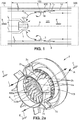
- turbomachine As shown in figure 1 .
- a turbomachine comprises a turbine hearth 100, a compressor 200 and a turbine 300.
- the turbine hearth 100 itself comprises a combustion chamber 101, an air supply system, and at least two systems with variable openings.
- the combustion chamber 101 can have different designs, such as, for example, a side wall chamber which is constituted by a succession of several rings 1a, 1b, 1c and 1d. In other designs of the combustion chamber 101, its side wall may be porous or have multiple perforations.
- the air supply system comprises at least one external duct 102 for guiding the air which emanates from the compressor 200 towards the air inlets of the combustion chamber 101.
- the arrows which are referenced by the letter E in the diagram. figure 1 denote the general direction of air flow in the turbomachine, from the compressor 200 to the turbine 300 through the combustion chamber 100.
- the references L denote air flow lines.
- the temperature of the air which comes from the compressor 200 can vary between approximately -40 ° C and approximately 630 ° C.
- variable opening system is arranged on the air flow path between the supply system and certain air inlets of the combustion chamber 101.
- a variable opening system 1 can be arranged axially through it. the upstream wall of the combustion chamber 101, to adjust a flow of combustion air, called the flow of primary air in the jargon of those skilled in the art.
- one or more variable opening system (s) 3 can be arranged through some of the segments 1a-1d of the side wall of the combustion chamber 101, each of which the latter systems being intended to adjust a flow of dilution air. All of these variable opening systems 1 and 3 are adjusted during operation of the turbomachine as a function of its operating speed, corresponding to a power delivered which is low or high.
- variable opening system 1 is adjusted to increase the primary air flow, and the systems 3 are adjusted simultaneously to reduce or eliminate the dilution of the combustion flame.
- variable opening system 1 is adjusted to reduce the primary air flow, and the variable opening systems 3 are simultaneously adjusted to increase the dilution of the flame, when the power which is delivered by the turbomachine decreases.
- the settings of the variable opening systems 1 and 3 are preferably provided so that the total mass flow of air entering the combustion chamber 101 and the flow pressure drop remain substantially constant during the transition of focus geometry.
- variable opening systems 1 and / or 3 is automatically and autonomously adjusted as a function of the temperature of the air in the pipe 102 upstream of this (these) system (s). ) with variable opening (s).
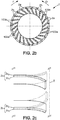
- the air supply system then comprises a supply swirler 103.
- This supply swirler comprises channels 103a for the combustion air, which open out through the upstream wall of the chamber. combustion 101, also called the combustion chamber bottom wall.
- Two channels 103a which are adjacent in the ring 103 are separated by an intermediate partition 103b, also called a blading.
- External peripheral openings of the channels 103a are distributed around an axis AA. They form an intake passage to allow the air which comes from the compressor 200 to enter the intake chamber 101.
- a crown with openings 2 is placed around the swirler 103, in front of the external peripheral openings.
- openings 2a are alternated with shutter segments 2b at the level of the outer peripheral openings of the channels 103a of the supply auger 103. Then, in a position of the crown 2 which corresponds to a section of maximum access to the channels 103a of the swirler 103 for the air which comes from the compressor 200, the openings 2a of the ring 2 coincide with those of the channels 103a of the spinner 103. Such a position of the ring 2 which produces the section d maximum access is shown in the left half of the figure 2b .
- the shutter segments 2b When the crown 2 is gradually rotated from this position, the shutter segments 2b partially come in front of the outer peripheral openings of the channels 103a of the auger 103, and thus reduce the section of access to the channels 103a for the air which. comes from the compressor 200.
- Such another position of the crown 2 which produces a reduced access section is shown in the right half of the figure 2b .
- the primary air flow entering the chamber combustion 101 is thus adjusted by rotating the crown 2 around the axis AA.
- the crown 2 forms the closure element which has been mentioned in the general part of the present description.
- the directions of rotation noted O and F on the figure 2b for the crown 2 correspond respectively to the progressive increase and the progressive reduction of the section of access to the channels 103a of the spinner 103, and consequently to the increase and the reduction, respectively, of the opening section of the passage intake to the combustion chamber 101 for the primary air flow.
- the crown 2 is provided with vanes 2c, for example upstream of the openings 2a and of the shutter segments 2b.
- vanes 2c are located in the air flow which comes from the compressor 200 before this flow partially enters the channels 103a of the swirler 103 or flows around the combustion chamber 101.
- the blades 2c are made up of at least partly by a shape memory alloy, so that they each have a curvature of varying direction.
- the curvature of the blades 2c is such that the air flow which comes from the compressor 200 pushes the crown 2 in the direction of rotation O indicated on the figure 2b , to increase the section of access to the channels 103a of the swirler 103.
- the shape memory alloy blades 2c constitute the heat-sensitive element mentioned in the general part of the present description.
- each blade 2c of the ring 2 is formed by a bimetallic assembly in its part with invertible curvature.
- Such an assembly can be formed by two segments 2c 1 and 2c 2 which are rolled together, for example cold, so as to each form a part of the thickness of the blade part with invertible curvature.
- the segment which is concave at lower temperature for example segment 2c 1 for the blade profiles which are indicated in solid lines in the figure 2c , is made of a material which has a thermal expansion coefficient value greater than that of the material of the other segment, 2c 2 in the example considered.
- the vanes of the ring 2 now referenced 2c ', have fixed curvatures in the air flow which comes from the compressor, to push the ring 2 in the direction of rotation O.
- the ring 2 and the system of air supply are then provided with arms 2d and 104, respectively, which are connected one-to-one by a shape memory alloy cable 4.
- the cable 4 can be designed to have, at a temperature above the martensitic temperature , an effective length which is greater than that effective below the martensitic temperature.
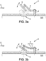
- variable opening systems 3 which is installed on the side wall of the combustion chamber 101, in a downstream part thereof.
- a system is intended to adapt a flow of dilution air which is admitted into the combustion chamber 101, as a function of the power regime which is in progress for the turbomachine.
- the side wall of the combustion chamber 101 is provided with an orifice 5, and a valve 6, acting as a closure element, is supported by a base 8 via a lever 7.
- the base 8 is preferably made of a thermally insulating material and integral with the side wall of the combustion chamber 101.
- the lever 7 is located in the air flow E which comes from the compressor 200. It is designed to apply the valve.
- At least one segment of the lever 7 is formed by a portion of shape memory alloy, such that the lever 7 is bent in the martensite phase to move the valve 6 away from the orifice 5, and is straight in the austenite phase to apply the valve 6 to the orifice 5.
- shape memory alloy such that the lever 7 is bent in the martensite phase to move the valve 6 away from the orifice 5, and is straight in the austenite phase to apply the valve 6 to the orifice 5.
- other geometric configurations can be used in an equivalent manner for the lever 7 and the base 8.
- the portion of shape memory alloy which constitutes the lever 7 is replaced by a heat-sensitive bimetal assembly as described with reference to figure 2c .
- the segments of this bimetal assembly are referenced 7 1 and 7 2 .
- the segment 7 1 which has a thermal expansion coefficient value greater than that of the segment 7 2 , constitutes the face of the lever 7 which is concave at a lower temperature, or at least part of this face.
- the two segments 7 1 and 7 2 of lever 7 are dimensioned thickness, and their respective materials are chosen, in a way which is within the reach of a person skilled in the art, so that the operation of the bimetal assembly reversibly produces the application of the valve 6 on the orifice 5 when the temperature of the air which comes from the compressor 200 is high, and the spacing of the valve 6 relative to the orifice 5 when this air temperature decreases.
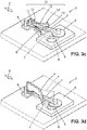
- the base 8 ' is configured to allow the lever 7 to rotate in a plane parallel to the outer side surface of the combustion chamber 101.
- the valve 6, which is carried by the lever 7 slides on the side surface exterior of the combustion chamber 101 between a position which is offset with respect to the orifice 5 (shown in solid lines), so that this orifice is then open, and a position in which the valve 6 closes off the orifice 5 ( shown in broken lines).
- the lever 7 rigidly carries a curved fin 9, of fixed shape, which is located in the air flow E coming from the compressor 200. In this way, the lever 7 is returned to the open position of the orifice 5. by the aerodynamic force which is produced by the air flow E on the fin 9.
- the fin 9 in the air flow E thus forms a return member of the system with variable opening towards the open position of the orifice 5.
- This open position corresponds to the rest position mentioned in the general part of the present description.
- An actuator 10 comprises another base 11, which can also be fixed to the wall of the combustion chamber 101, another lever 12 which is rigidly held at a fixing end 12 'in the base 11, and a thrust finger 13.
- the pusher finger 13 is attached to a distal end 12 "of the lever 12, which is opposite the attachment end 12 '.
- the lever 12 may consist of a portion of shape memory alloy which is designed so that, in the martensite phase, the lever 12 has a recessed shape (shown in solid lines in the figure 3c ) to allow the fin 9 to push the valve 6 into the position which is away from the orifice 5.
- the lever 12 is simultaneously designed so that, during its transition to its austenite phase, it pushes the lever 7 by means of the finger 13, until the valve 6 is brought above the orifice 5, so as to close the latter.
- the portion of shape memory alloy which constitutes the lever 12 of the actuator 10 can be replaced by a bimetal assembly as described with reference to figure 2c .
- a bimetal assembly as described with reference to figure 2c .
- FIG. 3d figure Yet another alternative embodiment is illustrated by 3d figure .
- the actuator 10 is omitted, and a vane with tilting and / or reversible curvature 7 'is carried by the lever 7.
- the vane 7' can be constituted by a portion of a shape memory alloy as described for blades 2c of the embodiment of the figure 2a , or else be constituted by a heat-sensitive bimetal assembly as described for the blades 2c 'of the embodiment of the figure 2c .
- Such another embodiment will also appear clearly to a person skilled in the art in the light of the descriptions which have already been provided with reference to these prior figures.
- FIG. 4 shows a combination of two of these embodiments: one in accordance with figures 2a-2c , and the other conforms to the 3d figure .
- Such a combination is in fact particularly simple to produce and then to use with a high level of reliability.
- each variable opening system is advantageously sized so that the total mass flow of air entering the chamber 101, as combustion air through the variable opening system 1 or as dilution air through the variable opening system 3, remains substantially constant during transitions since the open sections of the variable opening systems 1 and 3 vary in opposite directions, while maintaining a total open section which is substantially constant.
Landscapes
- Engineering & Computer Science (AREA)
- Chemical & Material Sciences (AREA)
- Combustion & Propulsion (AREA)
- Mechanical Engineering (AREA)
- General Engineering & Computer Science (AREA)
- Physics & Mathematics (AREA)
- Fluid Mechanics (AREA)
- Control Of Turbines (AREA)
- Structures Of Non-Positive Displacement Pumps (AREA)
- Supercharger (AREA)
- Air Supply (AREA)
Priority Applications (1)
| Application Number | Priority Date | Filing Date | Title |
|---|---|---|---|
| PL18719964T PL3610197T3 (pl) | 2017-04-11 | 2018-04-11 | Palenisko turbiny gazowej o samonastawnej geometrii zmiennej |
Applications Claiming Priority (2)
| Application Number | Priority Date | Filing Date | Title |
|---|---|---|---|
| FR1753165A FR3065059B1 (fr) | 2017-04-11 | 2017-04-11 | Foyer de turbine a gaz a geometrie variable auto-adaptative |
| PCT/FR2018/050907 WO2018189481A1 (fr) | 2017-04-11 | 2018-04-11 | Foyer de turbine a gaz a geometrie variable auto-adaptative |
Publications (2)
| Publication Number | Publication Date |
|---|---|
| EP3610197A1 EP3610197A1 (fr) | 2020-02-19 |
| EP3610197B1 true EP3610197B1 (fr) | 2021-06-02 |
Family
ID=59699772
Family Applications (1)
| Application Number | Title | Priority Date | Filing Date |
|---|---|---|---|
| EP18719964.1A Active EP3610197B1 (fr) | 2017-04-11 | 2018-04-11 | Foyer de turbine a gaz a geometrie variable auto-adaptative |
Country Status (8)
| Country | Link |
|---|---|
| US (1) | US11242992B2 (pl) |
| EP (1) | EP3610197B1 (pl) |
| JP (1) | JP7042840B2 (pl) |
| CN (1) | CN110678696B (pl) |
| FR (1) | FR3065059B1 (pl) |
| PL (1) | PL3610197T3 (pl) |
| RU (1) | RU2771114C2 (pl) |
| WO (1) | WO2018189481A1 (pl) |
Families Citing this family (17)
| Publication number | Priority date | Publication date | Assignee | Title |
|---|---|---|---|---|
| FR3108657B1 (fr) * | 2020-03-24 | 2022-07-15 | Safran Aircraft Engines | Rotor de turbine comprenant un dispositif de régulation du débit de fluide de refroidissement et turbomachine comprenant un tel rotor |
| FR3108659B1 (fr) * | 2020-03-24 | 2022-08-12 | Safran Aircraft Engines | Rotor de turbine comprenant un dispositif de régulation du débit de fluide de refroidissement et turbomachine comprenant un tel rotor |
| CN114593438B (zh) * | 2020-12-02 | 2023-08-22 | 中国航发商用航空发动机有限责任公司 | 燃油喷嘴、燃烧室、燃气涡轮发动机以及防止燃油结焦的方法 |
| CN112815356B (zh) * | 2020-12-31 | 2022-07-15 | 哈尔滨工程大学 | 一种可自适应调节的富氢燃料低排放微焰燃烧室 |
| CN112902226B (zh) * | 2021-03-11 | 2022-08-16 | 西北工业大学 | 一种燃油蒸发式的火焰筒 |
| CN113776083B (zh) * | 2021-10-08 | 2023-01-03 | 中山大学 | 一种可变形火焰稳定器 |
| CN114151826A (zh) * | 2021-10-20 | 2022-03-08 | 中国航发四川燃气涡轮研究院 | 变几何的燃烧室 |
| CN114321977A (zh) * | 2021-11-29 | 2022-04-12 | 南京航空航天大学 | 一种环缝帽罩进气面积智能调节系统及调节方法 |
| CN114234238B (zh) * | 2021-12-13 | 2023-05-30 | 中国船舶重工集团公司第七0三研究所 | 一种用于变几何燃烧室的可旋转高效密封装置 |
| US12123592B2 (en) * | 2022-01-12 | 2024-10-22 | General Electric Company | Fuel nozzle and swirler |
| CN114076324B (zh) * | 2022-01-19 | 2022-07-08 | 中国航发四川燃气涡轮研究院 | 能够自动调节掺混进气的燃烧室 |
| CN116592391A (zh) * | 2022-02-07 | 2023-08-15 | 通用电气公司 | 具有可变初级区燃烧室的燃烧器 |
| CN116592392A (zh) * | 2022-02-07 | 2023-08-15 | 通用电气公司 | 操作具有可变燃烧室的燃烧器的方法 |
| CN116293813B (zh) * | 2023-02-23 | 2025-02-18 | 中国航发沈阳发动机研究所 | 一种两级涡流器可调的变几何燃烧室 |
| CN116255644B (zh) * | 2023-02-23 | 2024-08-02 | 中国航发沈阳发动机研究所 | 一种单级涡流器可调的变几何燃烧室 |
| US20240318821A1 (en) * | 2023-03-20 | 2024-09-26 | General Electric Company | Combustor with a dilution passage |
| CN119844793B (zh) * | 2025-03-20 | 2025-05-16 | 中国人民解放军国防科技大学 | 燃烧稳焰增强的波纹壁激波发生器 |
Family Cites Families (19)
| Publication number | Priority date | Publication date | Assignee | Title |
|---|---|---|---|---|
| US3691761A (en) * | 1967-11-10 | 1972-09-19 | Squire Ronald Jackson | Apparatus for regulation of airflow to flame tubes for gas turbine engines |
| US3577878A (en) * | 1967-11-10 | 1971-05-11 | Lucas Industries Ltd | Flame tubes for gas turbine engines |
| DE2020416A1 (de) * | 1970-04-27 | 1971-11-11 | Motoren Turbinen Union | Brennkammer fuer Gasturbinentriebwerke |
| US4296599A (en) * | 1979-03-30 | 1981-10-27 | General Electric Company | Turbine cooling air modulation apparatus |
| GB2085147A (en) * | 1980-10-01 | 1982-04-21 | Gen Electric | Flow modifying device |
| US4606190A (en) * | 1982-07-22 | 1986-08-19 | United Technologies Corporation | Variable area inlet guide vanes |
| IT1248305B (it) * | 1990-05-29 | 1995-01-05 | Gen Electric | Formatore di vortici automatico a geometria variabile |
| FR2779807B1 (fr) | 1998-06-11 | 2000-07-13 | Inst Francais Du Petrole | Chambre de combustion de turbine a gaz a geometrie variable |
| JP2000257861A (ja) * | 1999-03-11 | 2000-09-22 | Senshin Zairyo Riyo Gas Generator Kenkyusho:Kk | ガスタービン用燃焼装置 |
| EP2107306A1 (en) | 2008-03-31 | 2009-10-07 | Siemens Aktiengesellschaft | A combustor casing |
| JP5898069B2 (ja) * | 2009-06-05 | 2016-04-06 | エクソンモービル アップストリーム リサーチ カンパニー | 燃焼器システムおよびその使用方法 |
| US8024932B1 (en) * | 2010-04-07 | 2011-09-27 | General Electric Company | System and method for a combustor nozzle |
| JP5488301B2 (ja) * | 2010-07-28 | 2014-05-14 | 株式会社Ihi | 燃焼器 |
| DE102010043864A1 (de) | 2010-11-12 | 2012-05-16 | BSH Bosch und Siemens Hausgeräte GmbH | Rührschüssel für eine Küchenmaschine |
| FR2996285B1 (fr) * | 2012-10-01 | 2014-09-12 | Turbomeca | Ensemble de combustion de turbomachine a variation d'alimentation d'air. |
| US9470395B2 (en) | 2013-03-15 | 2016-10-18 | Abl Ip Holding Llc | Optic for a light source |
| EP2921779B1 (en) * | 2014-03-18 | 2017-12-06 | Ansaldo Energia Switzerland AG | Combustion chamber with cooling sleeve |
| US9845731B2 (en) * | 2014-09-24 | 2017-12-19 | United Technologies Corporation | Self-modulated cooling on turbine components |
| RU2753202C1 (ru) | 2020-10-09 | 2021-08-12 | Открытое акционерное общество "Всероссийский дважды ордена Трудового Красного Знамени теплотехнический научно-исследовательский институт" (ОАО "ВТИ") | Малоэмиссионная камера сгорания с двумя зонами кинетического горения |
-
2017
- 2017-04-11 FR FR1753165A patent/FR3065059B1/fr not_active Expired - Fee Related
-
2018
- 2018-04-11 JP JP2019555476A patent/JP7042840B2/ja active Active
- 2018-04-11 EP EP18719964.1A patent/EP3610197B1/fr active Active
- 2018-04-11 WO PCT/FR2018/050907 patent/WO2018189481A1/fr not_active Ceased
- 2018-04-11 PL PL18719964T patent/PL3610197T3/pl unknown
- 2018-04-11 US US16/603,670 patent/US11242992B2/en active Active
- 2018-04-11 CN CN201880024656.3A patent/CN110678696B/zh active Active
- 2018-04-11 RU RU2019135837A patent/RU2771114C2/ru active
Non-Patent Citations (1)
| Title |
|---|
| None * |
Also Published As
| Publication number | Publication date |
|---|---|
| RU2771114C2 (ru) | 2022-04-26 |
| US20210108574A1 (en) | 2021-04-15 |
| EP3610197A1 (fr) | 2020-02-19 |
| CN110678696B (zh) | 2021-02-02 |
| PL3610197T3 (pl) | 2021-11-22 |
| JP7042840B2 (ja) | 2022-03-28 |
| RU2019135837A (ru) | 2021-05-11 |
| RU2019135837A3 (pl) | 2021-11-12 |
| CN110678696A (zh) | 2020-01-10 |
| FR3065059B1 (fr) | 2020-11-06 |
| US11242992B2 (en) | 2022-02-08 |
| JP2020516841A (ja) | 2020-06-11 |
| CA3058632A1 (fr) | 2018-10-18 |
| FR3065059A1 (fr) | 2018-10-12 |
| WO2018189481A1 (fr) | 2018-10-18 |
Similar Documents
| Publication | Publication Date | Title |
|---|---|---|
| WO2018189481A1 (fr) | Foyer de turbine a gaz a geometrie variable auto-adaptative | |
| EP2472067B1 (fr) | Intégration d'un échangeur de chaleur surfacique avec débit d'air régulé dans un moteur d'avion | |
| EP0942156B1 (fr) | Organe d'échappement à échangeur de chaleur | |
| EP0094296A1 (fr) | Dispositif de réglage de la perte de charge d'au moins un des flux dans un turboréacteur multiflux | |
| FR3057620A1 (fr) | Ensemble propulsif comprenant un conduit d'alimentation du generateur de gaz dans un carter inter-veine | |
| EP3329101B1 (fr) | Systeme d'antigivrage d'une aube de turbomachine. | |
| FR2590320A1 (fr) | Turboreacteur a deux flux et plusieurs arbres a refroidissement par l'intermediaire du canal secondaire s'etendant pratiquement sur toute la longueur de la machine | |
| EP1555394B1 (fr) | Dispositif de contrôle de jeu dans une turbine à gaz | |
| EP2096357B1 (fr) | Accroche flamme pour canal de réchauffe d'un turboréacteur avec une semelle d'écartement, canal de réchauffe et turboréacteur comprenant un canal de réchauffe | |
| EP3559434B1 (fr) | Nacelle de turboréacteur d'aéronef | |
| WO2017013360A1 (fr) | Aeronef comportant une turbomachine integree au fuselage arriere a alimentation variable | |
| CA2558799A1 (fr) | Pilotage de jeu au sommet d`aubes de rotor de turbine dans un moteur a turbine a gaz | |
| EP2964946B1 (fr) | Tuyere a section de col variable de propulseur d'engin aerospatial munie d'un pointeau mobile | |
| WO1997018389A1 (fr) | Inverseur de poussee de turboreacteur a obstacles aval tendant a l'equilibrage | |
| FR2900388A1 (fr) | Ensemble d'echappement des gaz de propulsion dans un aeronef formant un coude | |
| EP1462615A1 (fr) | Dispositif d'injection d'air de refroidissement dans un rotor de turbine | |
| WO2020245525A1 (fr) | Structure de confluence d'une veine primaire et d'une veine secondaire dans une turbomachine a double flux | |
| FR2473624A1 (fr) | Tubulure d'echappement de turbine | |
| FR2921977A1 (fr) | Turbomoteur a double flux pour aeronef | |
| EP0626513A1 (fr) | Tuyère de moteur-fusée à section de sortie sélectivement réduite | |
| CA3058632C (fr) | Foyer de turbine a gaz a geometrie variable auto-adaptative | |
| FR2916475A1 (fr) | Circuit d'alimentation en air de ventilation d'un rotor de turbine dans un moteur a turbine a gaz | |
| FR3066783B1 (fr) | Chemise pour aube de turbine a refroidissement optimise | |
| FR3052191B1 (fr) | Inversion de poussee dans une turbomachine avec soufflante a calage variable | |
| EP3768949B1 (fr) | Aube fixe de turbine à refroidissement par impacts de jets d'air |
Legal Events
| Date | Code | Title | Description |
|---|---|---|---|
| STAA | Information on the status of an ep patent application or granted ep patent |
Free format text: STATUS: UNKNOWN |
|
| STAA | Information on the status of an ep patent application or granted ep patent |
Free format text: STATUS: THE INTERNATIONAL PUBLICATION HAS BEEN MADE |
|
| PUAI | Public reference made under article 153(3) epc to a published international application that has entered the european phase |
Free format text: ORIGINAL CODE: 0009012 |
|
| STAA | Information on the status of an ep patent application or granted ep patent |
Free format text: STATUS: REQUEST FOR EXAMINATION WAS MADE |
|
| 17P | Request for examination filed |
Effective date: 20191021 |
|
| AK | Designated contracting states |
Kind code of ref document: A1 Designated state(s): AL AT BE BG CH CY CZ DE DK EE ES FI FR GB GR HR HU IE IS IT LI LT LU LV MC MK MT NL NO PL PT RO RS SE SI SK SM TR |
|
| AX | Request for extension of the european patent |
Extension state: BA ME |
|
| DAV | Request for validation of the european patent (deleted) | ||
| DAX | Request for extension of the european patent (deleted) | ||
| GRAP | Despatch of communication of intention to grant a patent |
Free format text: ORIGINAL CODE: EPIDOSNIGR1 |
|
| STAA | Information on the status of an ep patent application or granted ep patent |
Free format text: STATUS: GRANT OF PATENT IS INTENDED |
|
| INTG | Intention to grant announced |
Effective date: 20210113 |
|
| GRAS | Grant fee paid |
Free format text: ORIGINAL CODE: EPIDOSNIGR3 |
|
| GRAA | (expected) grant |
Free format text: ORIGINAL CODE: 0009210 |
|
| STAA | Information on the status of an ep patent application or granted ep patent |
Free format text: STATUS: THE PATENT HAS BEEN GRANTED |
|
| REG | Reference to a national code |
Ref country code: CH Ref legal event code: EP |
|
| AK | Designated contracting states |
Kind code of ref document: B1 Designated state(s): AL AT BE BG CH CY CZ DE DK EE ES FI FR GB GR HR HU IE IS IT LI LT LU LV MC MK MT NL NO PL PT RO RS SE SI SK SM TR |
|
| REG | Reference to a national code |
Ref country code: GB Ref legal event code: FG4D Free format text: NOT ENGLISH |
|
| REG | Reference to a national code |
Ref country code: AT Ref legal event code: REF Ref document number: 1398798 Country of ref document: AT Kind code of ref document: T Effective date: 20210615 |
|
| REG | Reference to a national code |
Ref country code: IE Ref legal event code: FG4D Free format text: LANGUAGE OF EP DOCUMENT: FRENCH |
|
| REG | Reference to a national code |
Ref country code: DE Ref legal event code: R096 Ref document number: 602018018041 Country of ref document: DE |
|
| REG | Reference to a national code |
Ref country code: SE Ref legal event code: TRGR |
|
| REG | Reference to a national code |
Ref country code: LT Ref legal event code: MG9D |
|
| PG25 | Lapsed in a contracting state [announced via postgrant information from national office to epo] |
Ref country code: LT Free format text: LAPSE BECAUSE OF FAILURE TO SUBMIT A TRANSLATION OF THE DESCRIPTION OR TO PAY THE FEE WITHIN THE PRESCRIBED TIME-LIMIT Effective date: 20210602 Ref country code: HR Free format text: LAPSE BECAUSE OF FAILURE TO SUBMIT A TRANSLATION OF THE DESCRIPTION OR TO PAY THE FEE WITHIN THE PRESCRIBED TIME-LIMIT Effective date: 20210602 Ref country code: FI Free format text: LAPSE BECAUSE OF FAILURE TO SUBMIT A TRANSLATION OF THE DESCRIPTION OR TO PAY THE FEE WITHIN THE PRESCRIBED TIME-LIMIT Effective date: 20210602 Ref country code: BG Free format text: LAPSE BECAUSE OF FAILURE TO SUBMIT A TRANSLATION OF THE DESCRIPTION OR TO PAY THE FEE WITHIN THE PRESCRIBED TIME-LIMIT Effective date: 20210902 |
|
| REG | Reference to a national code |
Ref country code: NL Ref legal event code: MP Effective date: 20210602 |
|
| REG | Reference to a national code |
Ref country code: AT Ref legal event code: MK05 Ref document number: 1398798 Country of ref document: AT Kind code of ref document: T Effective date: 20210602 |
|
| PG25 | Lapsed in a contracting state [announced via postgrant information from national office to epo] |
Ref country code: GR Free format text: LAPSE BECAUSE OF FAILURE TO SUBMIT A TRANSLATION OF THE DESCRIPTION OR TO PAY THE FEE WITHIN THE PRESCRIBED TIME-LIMIT Effective date: 20210903 Ref country code: RS Free format text: LAPSE BECAUSE OF FAILURE TO SUBMIT A TRANSLATION OF THE DESCRIPTION OR TO PAY THE FEE WITHIN THE PRESCRIBED TIME-LIMIT Effective date: 20210602 Ref country code: LV Free format text: LAPSE BECAUSE OF FAILURE TO SUBMIT A TRANSLATION OF THE DESCRIPTION OR TO PAY THE FEE WITHIN THE PRESCRIBED TIME-LIMIT Effective date: 20210602 Ref country code: NO Free format text: LAPSE BECAUSE OF FAILURE TO SUBMIT A TRANSLATION OF THE DESCRIPTION OR TO PAY THE FEE WITHIN THE PRESCRIBED TIME-LIMIT Effective date: 20210902 |
|
| PG25 | Lapsed in a contracting state [announced via postgrant information from national office to epo] |
Ref country code: SK Free format text: LAPSE BECAUSE OF FAILURE TO SUBMIT A TRANSLATION OF THE DESCRIPTION OR TO PAY THE FEE WITHIN THE PRESCRIBED TIME-LIMIT Effective date: 20210602 Ref country code: SM Free format text: LAPSE BECAUSE OF FAILURE TO SUBMIT A TRANSLATION OF THE DESCRIPTION OR TO PAY THE FEE WITHIN THE PRESCRIBED TIME-LIMIT Effective date: 20210602 Ref country code: ES Free format text: LAPSE BECAUSE OF FAILURE TO SUBMIT A TRANSLATION OF THE DESCRIPTION OR TO PAY THE FEE WITHIN THE PRESCRIBED TIME-LIMIT Effective date: 20210602 Ref country code: EE Free format text: LAPSE BECAUSE OF FAILURE TO SUBMIT A TRANSLATION OF THE DESCRIPTION OR TO PAY THE FEE WITHIN THE PRESCRIBED TIME-LIMIT Effective date: 20210602 Ref country code: PT Free format text: LAPSE BECAUSE OF FAILURE TO SUBMIT A TRANSLATION OF THE DESCRIPTION OR TO PAY THE FEE WITHIN THE PRESCRIBED TIME-LIMIT Effective date: 20211004 Ref country code: RO Free format text: LAPSE BECAUSE OF FAILURE TO SUBMIT A TRANSLATION OF THE DESCRIPTION OR TO PAY THE FEE WITHIN THE PRESCRIBED TIME-LIMIT Effective date: 20210602 Ref country code: NL Free format text: LAPSE BECAUSE OF FAILURE TO SUBMIT A TRANSLATION OF THE DESCRIPTION OR TO PAY THE FEE WITHIN THE PRESCRIBED TIME-LIMIT Effective date: 20210602 Ref country code: CZ Free format text: LAPSE BECAUSE OF FAILURE TO SUBMIT A TRANSLATION OF THE DESCRIPTION OR TO PAY THE FEE WITHIN THE PRESCRIBED TIME-LIMIT Effective date: 20210602 Ref country code: AT Free format text: LAPSE BECAUSE OF FAILURE TO SUBMIT A TRANSLATION OF THE DESCRIPTION OR TO PAY THE FEE WITHIN THE PRESCRIBED TIME-LIMIT Effective date: 20210602 |
|
| REG | Reference to a national code |
Ref country code: DE Ref legal event code: R097 Ref document number: 602018018041 Country of ref document: DE |
|
| PLBE | No opposition filed within time limit |
Free format text: ORIGINAL CODE: 0009261 |
|
| STAA | Information on the status of an ep patent application or granted ep patent |
Free format text: STATUS: NO OPPOSITION FILED WITHIN TIME LIMIT |
|
| PG25 | Lapsed in a contracting state [announced via postgrant information from national office to epo] |
Ref country code: DK Free format text: LAPSE BECAUSE OF FAILURE TO SUBMIT A TRANSLATION OF THE DESCRIPTION OR TO PAY THE FEE WITHIN THE PRESCRIBED TIME-LIMIT Effective date: 20210602 |
|
| 26N | No opposition filed |
Effective date: 20220303 |
|
| PG25 | Lapsed in a contracting state [announced via postgrant information from national office to epo] |
Ref country code: AL Free format text: LAPSE BECAUSE OF FAILURE TO SUBMIT A TRANSLATION OF THE DESCRIPTION OR TO PAY THE FEE WITHIN THE PRESCRIBED TIME-LIMIT Effective date: 20210602 |
|
| REG | Reference to a national code |
Ref country code: CH Ref legal event code: PL |
|
| REG | Reference to a national code |
Ref country code: BE Ref legal event code: MM Effective date: 20220430 |
|
| PG25 | Lapsed in a contracting state [announced via postgrant information from national office to epo] |
Ref country code: MC Free format text: LAPSE BECAUSE OF FAILURE TO SUBMIT A TRANSLATION OF THE DESCRIPTION OR TO PAY THE FEE WITHIN THE PRESCRIBED TIME-LIMIT Effective date: 20210602 Ref country code: LU Free format text: LAPSE BECAUSE OF NON-PAYMENT OF DUE FEES Effective date: 20220411 Ref country code: LI Free format text: LAPSE BECAUSE OF NON-PAYMENT OF DUE FEES Effective date: 20220430 Ref country code: CH Free format text: LAPSE BECAUSE OF NON-PAYMENT OF DUE FEES Effective date: 20220430 |
|
| PG25 | Lapsed in a contracting state [announced via postgrant information from national office to epo] |
Ref country code: BE Free format text: LAPSE BECAUSE OF NON-PAYMENT OF DUE FEES Effective date: 20220430 |
|
| PG25 | Lapsed in a contracting state [announced via postgrant information from national office to epo] |
Ref country code: IE Free format text: LAPSE BECAUSE OF NON-PAYMENT OF DUE FEES Effective date: 20220411 |
|
| PG25 | Lapsed in a contracting state [announced via postgrant information from national office to epo] |
Ref country code: MK Free format text: LAPSE BECAUSE OF FAILURE TO SUBMIT A TRANSLATION OF THE DESCRIPTION OR TO PAY THE FEE WITHIN THE PRESCRIBED TIME-LIMIT Effective date: 20210602 Ref country code: CY Free format text: LAPSE BECAUSE OF FAILURE TO SUBMIT A TRANSLATION OF THE DESCRIPTION OR TO PAY THE FEE WITHIN THE PRESCRIBED TIME-LIMIT Effective date: 20210602 |
|
| PG25 | Lapsed in a contracting state [announced via postgrant information from national office to epo] |
Ref country code: HU Free format text: LAPSE BECAUSE OF FAILURE TO SUBMIT A TRANSLATION OF THE DESCRIPTION OR TO PAY THE FEE WITHIN THE PRESCRIBED TIME-LIMIT; INVALID AB INITIO Effective date: 20180411 |
|
| PG25 | Lapsed in a contracting state [announced via postgrant information from national office to epo] |
Ref country code: MT Free format text: LAPSE BECAUSE OF FAILURE TO SUBMIT A TRANSLATION OF THE DESCRIPTION OR TO PAY THE FEE WITHIN THE PRESCRIBED TIME-LIMIT Effective date: 20210602 |
|
| PGFP | Annual fee paid to national office [announced via postgrant information from national office to epo] |
Ref country code: SE Payment date: 20250313 Year of fee payment: 8 |
|
| PGFP | Annual fee paid to national office [announced via postgrant information from national office to epo] |
Ref country code: PL Payment date: 20250327 Year of fee payment: 8 |
|
| PGFP | Annual fee paid to national office [announced via postgrant information from national office to epo] |
Ref country code: DE Payment date: 20250528 Year of fee payment: 8 |
|
| PGFP | Annual fee paid to national office [announced via postgrant information from national office to epo] |
Ref country code: GB Payment date: 20250429 Year of fee payment: 8 |
|
| PGFP | Annual fee paid to national office [announced via postgrant information from national office to epo] |
Ref country code: IT Payment date: 20250425 Year of fee payment: 8 |
|
| PGFP | Annual fee paid to national office [announced via postgrant information from national office to epo] |
Ref country code: FR Payment date: 20250429 Year of fee payment: 8 |
|
| PG25 | Lapsed in a contracting state [announced via postgrant information from national office to epo] |
Ref country code: TR Free format text: LAPSE BECAUSE OF FAILURE TO SUBMIT A TRANSLATION OF THE DESCRIPTION OR TO PAY THE FEE WITHIN THE PRESCRIBED TIME-LIMIT Effective date: 20210602 |