EP3610163B1 - Multi-layer sintered bushings and bearings - Google Patents
Multi-layer sintered bushings and bearings Download PDFInfo
- Publication number
- EP3610163B1 EP3610163B1 EP18721631.2A EP18721631A EP3610163B1 EP 3610163 B1 EP3610163 B1 EP 3610163B1 EP 18721631 A EP18721631 A EP 18721631A EP 3610163 B1 EP3610163 B1 EP 3610163B1
- Authority
- EP
- European Patent Office
- Prior art keywords
- bushing
- total weight
- cobalt
- different
- alloy
- Prior art date
- Legal status (The legal status is an assumption and is not a legal conclusion. Google has not performed a legal analysis and makes no representation as to the accuracy of the status listed.)
- Active
Links
Images




Classifications
-
- F—MECHANICAL ENGINEERING; LIGHTING; HEATING; WEAPONS; BLASTING
- F16—ENGINEERING ELEMENTS AND UNITS; GENERAL MEASURES FOR PRODUCING AND MAINTAINING EFFECTIVE FUNCTIONING OF MACHINES OR INSTALLATIONS; THERMAL INSULATION IN GENERAL
- F16C—SHAFTS; FLEXIBLE SHAFTS; ELEMENTS OR CRANKSHAFT MECHANISMS; ROTARY BODIES OTHER THAN GEARING ELEMENTS; BEARINGS
- F16C33/00—Parts of bearings; Special methods for making bearings or parts thereof
- F16C33/02—Parts of sliding-contact bearings
- F16C33/04—Brasses; Bushes; Linings
- F16C33/06—Sliding surface mainly made of metal
- F16C33/12—Structural composition; Use of special materials or surface treatments, e.g. for rust-proofing
- F16C33/121—Use of special materials
-
- B—PERFORMING OPERATIONS; TRANSPORTING
- B22—CASTING; POWDER METALLURGY
- B22F—WORKING METALLIC POWDER; MANUFACTURE OF ARTICLES FROM METALLIC POWDER; MAKING METALLIC POWDER; APPARATUS OR DEVICES SPECIALLY ADAPTED FOR METALLIC POWDER
- B22F5/00—Manufacture of workpieces or articles from metallic powder characterised by the special shape of the product
- B22F5/10—Manufacture of workpieces or articles from metallic powder characterised by the special shape of the product of articles with cavities or holes, not otherwise provided for in the preceding subgroups
- B22F5/106—Tube or ring forms
-
- B—PERFORMING OPERATIONS; TRANSPORTING
- B22—CASTING; POWDER METALLURGY
- B22F—WORKING METALLIC POWDER; MANUFACTURE OF ARTICLES FROM METALLIC POWDER; MAKING METALLIC POWDER; APPARATUS OR DEVICES SPECIALLY ADAPTED FOR METALLIC POWDER
- B22F7/00—Manufacture of composite layers, workpieces, or articles, comprising metallic powder, by sintering the powder, with or without compacting wherein at least one part is obtained by sintering or compression
- B22F7/02—Manufacture of composite layers, workpieces, or articles, comprising metallic powder, by sintering the powder, with or without compacting wherein at least one part is obtained by sintering or compression of composite layers
-
- B—PERFORMING OPERATIONS; TRANSPORTING
- B22—CASTING; POWDER METALLURGY
- B22F—WORKING METALLIC POWDER; MANUFACTURE OF ARTICLES FROM METALLIC POWDER; MAKING METALLIC POWDER; APPARATUS OR DEVICES SPECIALLY ADAPTED FOR METALLIC POWDER
- B22F7/00—Manufacture of composite layers, workpieces, or articles, comprising metallic powder, by sintering the powder, with or without compacting wherein at least one part is obtained by sintering or compression
- B22F7/06—Manufacture of composite layers, workpieces, or articles, comprising metallic powder, by sintering the powder, with or without compacting wherein at least one part is obtained by sintering or compression of composite workpieces or articles from parts, e.g. to form tipped tools
- B22F7/062—Manufacture of composite layers, workpieces, or articles, comprising metallic powder, by sintering the powder, with or without compacting wherein at least one part is obtained by sintering or compression of composite workpieces or articles from parts, e.g. to form tipped tools involving the connection or repairing of preformed parts
- B22F7/064—Manufacture of composite layers, workpieces, or articles, comprising metallic powder, by sintering the powder, with or without compacting wherein at least one part is obtained by sintering or compression of composite workpieces or articles from parts, e.g. to form tipped tools involving the connection or repairing of preformed parts using an intermediate powder layer
-
- C—CHEMISTRY; METALLURGY
- C22—METALLURGY; FERROUS OR NON-FERROUS ALLOYS; TREATMENT OF ALLOYS OR NON-FERROUS METALS
- C22C—ALLOYS
- C22C38/00—Ferrous alloys, e.g. steel alloys
- C22C38/18—Ferrous alloys, e.g. steel alloys containing chromium
- C22C38/40—Ferrous alloys, e.g. steel alloys containing chromium with nickel
- C22C38/44—Ferrous alloys, e.g. steel alloys containing chromium with nickel with molybdenum or tungsten
-
- C—CHEMISTRY; METALLURGY
- C22—METALLURGY; FERROUS OR NON-FERROUS ALLOYS; TREATMENT OF ALLOYS OR NON-FERROUS METALS
- C22C—ALLOYS
- C22C38/00—Ferrous alloys, e.g. steel alloys
- C22C38/18—Ferrous alloys, e.g. steel alloys containing chromium
- C22C38/40—Ferrous alloys, e.g. steel alloys containing chromium with nickel
- C22C38/46—Ferrous alloys, e.g. steel alloys containing chromium with nickel with vanadium
-
- C—CHEMISTRY; METALLURGY
- C22—METALLURGY; FERROUS OR NON-FERROUS ALLOYS; TREATMENT OF ALLOYS OR NON-FERROUS METALS
- C22C—ALLOYS
- C22C38/00—Ferrous alloys, e.g. steel alloys
- C22C38/18—Ferrous alloys, e.g. steel alloys containing chromium
- C22C38/40—Ferrous alloys, e.g. steel alloys containing chromium with nickel
- C22C38/52—Ferrous alloys, e.g. steel alloys containing chromium with nickel with cobalt
-
- F—MECHANICAL ENGINEERING; LIGHTING; HEATING; WEAPONS; BLASTING
- F16—ENGINEERING ELEMENTS AND UNITS; GENERAL MEASURES FOR PRODUCING AND MAINTAINING EFFECTIVE FUNCTIONING OF MACHINES OR INSTALLATIONS; THERMAL INSULATION IN GENERAL
- F16C—SHAFTS; FLEXIBLE SHAFTS; ELEMENTS OR CRANKSHAFT MECHANISMS; ROTARY BODIES OTHER THAN GEARING ELEMENTS; BEARINGS
- F16C17/00—Sliding-contact bearings for exclusively rotary movement
- F16C17/02—Sliding-contact bearings for exclusively rotary movement for radial load only
-
- F—MECHANICAL ENGINEERING; LIGHTING; HEATING; WEAPONS; BLASTING
- F16—ENGINEERING ELEMENTS AND UNITS; GENERAL MEASURES FOR PRODUCING AND MAINTAINING EFFECTIVE FUNCTIONING OF MACHINES OR INSTALLATIONS; THERMAL INSULATION IN GENERAL
- F16C—SHAFTS; FLEXIBLE SHAFTS; ELEMENTS OR CRANKSHAFT MECHANISMS; ROTARY BODIES OTHER THAN GEARING ELEMENTS; BEARINGS
- F16C17/00—Sliding-contact bearings for exclusively rotary movement
- F16C17/12—Sliding-contact bearings for exclusively rotary movement characterised by features not related to the direction of the load
- F16C17/24—Sliding-contact bearings for exclusively rotary movement characterised by features not related to the direction of the load with devices affected by abnormal or undesired positions, e.g. for preventing overheating, for safety
- F16C17/243—Sliding-contact bearings for exclusively rotary movement characterised by features not related to the direction of the load with devices affected by abnormal or undesired positions, e.g. for preventing overheating, for safety related to temperature and heat, e.g. for preventing overheating
-
- F—MECHANICAL ENGINEERING; LIGHTING; HEATING; WEAPONS; BLASTING
- F16—ENGINEERING ELEMENTS AND UNITS; GENERAL MEASURES FOR PRODUCING AND MAINTAINING EFFECTIVE FUNCTIONING OF MACHINES OR INSTALLATIONS; THERMAL INSULATION IN GENERAL
- F16C—SHAFTS; FLEXIBLE SHAFTS; ELEMENTS OR CRANKSHAFT MECHANISMS; ROTARY BODIES OTHER THAN GEARING ELEMENTS; BEARINGS
- F16C17/00—Sliding-contact bearings for exclusively rotary movement
- F16C17/12—Sliding-contact bearings for exclusively rotary movement characterised by features not related to the direction of the load
- F16C17/24—Sliding-contact bearings for exclusively rotary movement characterised by features not related to the direction of the load with devices affected by abnormal or undesired positions, e.g. for preventing overheating, for safety
- F16C17/246—Sliding-contact bearings for exclusively rotary movement characterised by features not related to the direction of the load with devices affected by abnormal or undesired positions, e.g. for preventing overheating, for safety related to wear, e.g. sensors for measuring wear
-
- F—MECHANICAL ENGINEERING; LIGHTING; HEATING; WEAPONS; BLASTING
- F16—ENGINEERING ELEMENTS AND UNITS; GENERAL MEASURES FOR PRODUCING AND MAINTAINING EFFECTIVE FUNCTIONING OF MACHINES OR INSTALLATIONS; THERMAL INSULATION IN GENERAL
- F16C—SHAFTS; FLEXIBLE SHAFTS; ELEMENTS OR CRANKSHAFT MECHANISMS; ROTARY BODIES OTHER THAN GEARING ELEMENTS; BEARINGS
- F16C33/00—Parts of bearings; Special methods for making bearings or parts thereof
- F16C33/02—Parts of sliding-contact bearings
- F16C33/04—Brasses; Bushes; Linings
- F16C33/06—Sliding surface mainly made of metal
- F16C33/12—Structural composition; Use of special materials or surface treatments, e.g. for rust-proofing
- F16C33/122—Multilayer structures of sleeves, washers or liners
-
- F—MECHANICAL ENGINEERING; LIGHTING; HEATING; WEAPONS; BLASTING
- F16—ENGINEERING ELEMENTS AND UNITS; GENERAL MEASURES FOR PRODUCING AND MAINTAINING EFFECTIVE FUNCTIONING OF MACHINES OR INSTALLATIONS; THERMAL INSULATION IN GENERAL
- F16C—SHAFTS; FLEXIBLE SHAFTS; ELEMENTS OR CRANKSHAFT MECHANISMS; ROTARY BODIES OTHER THAN GEARING ELEMENTS; BEARINGS
- F16C33/00—Parts of bearings; Special methods for making bearings or parts thereof
- F16C33/02—Parts of sliding-contact bearings
- F16C33/04—Brasses; Bushes; Linings
- F16C33/06—Sliding surface mainly made of metal
- F16C33/12—Structural composition; Use of special materials or surface treatments, e.g. for rust-proofing
- F16C33/122—Multilayer structures of sleeves, washers or liners
- F16C33/125—Details of bearing layers, i.e. the lining
-
- F—MECHANICAL ENGINEERING; LIGHTING; HEATING; WEAPONS; BLASTING
- F16—ENGINEERING ELEMENTS AND UNITS; GENERAL MEASURES FOR PRODUCING AND MAINTAINING EFFECTIVE FUNCTIONING OF MACHINES OR INSTALLATIONS; THERMAL INSULATION IN GENERAL
- F16C—SHAFTS; FLEXIBLE SHAFTS; ELEMENTS OR CRANKSHAFT MECHANISMS; ROTARY BODIES OTHER THAN GEARING ELEMENTS; BEARINGS
- F16C33/00—Parts of bearings; Special methods for making bearings or parts thereof
- F16C33/02—Parts of sliding-contact bearings
- F16C33/04—Brasses; Bushes; Linings
- F16C33/06—Sliding surface mainly made of metal
- F16C33/12—Structural composition; Use of special materials or surface treatments, e.g. for rust-proofing
- F16C33/128—Porous bearings, e.g. bushes of sintered alloy
-
- F—MECHANICAL ENGINEERING; LIGHTING; HEATING; WEAPONS; BLASTING
- F16—ENGINEERING ELEMENTS AND UNITS; GENERAL MEASURES FOR PRODUCING AND MAINTAINING EFFECTIVE FUNCTIONING OF MACHINES OR INSTALLATIONS; THERMAL INSULATION IN GENERAL
- F16C—SHAFTS; FLEXIBLE SHAFTS; ELEMENTS OR CRANKSHAFT MECHANISMS; ROTARY BODIES OTHER THAN GEARING ELEMENTS; BEARINGS
- F16C33/00—Parts of bearings; Special methods for making bearings or parts thereof
- F16C33/02—Parts of sliding-contact bearings
- F16C33/04—Brasses; Bushes; Linings
- F16C33/06—Sliding surface mainly made of metal
- F16C33/14—Special methods of manufacture; Running-in
- F16C33/145—Special methods of manufacture; Running-in of sintered porous bearings
-
- F—MECHANICAL ENGINEERING; LIGHTING; HEATING; WEAPONS; BLASTING
- F16—ENGINEERING ELEMENTS AND UNITS; GENERAL MEASURES FOR PRODUCING AND MAINTAINING EFFECTIVE FUNCTIONING OF MACHINES OR INSTALLATIONS; THERMAL INSULATION IN GENERAL
- F16C—SHAFTS; FLEXIBLE SHAFTS; ELEMENTS OR CRANKSHAFT MECHANISMS; ROTARY BODIES OTHER THAN GEARING ELEMENTS; BEARINGS
- F16C33/00—Parts of bearings; Special methods for making bearings or parts thereof
- F16C33/02—Parts of sliding-contact bearings
- F16C33/04—Brasses; Bushes; Linings
- F16C33/24—Brasses; Bushes; Linings with different areas of the sliding surface consisting of different materials
-
- B—PERFORMING OPERATIONS; TRANSPORTING
- B22—CASTING; POWDER METALLURGY
- B22F—WORKING METALLIC POWDER; MANUFACTURE OF ARTICLES FROM METALLIC POWDER; MAKING METALLIC POWDER; APPARATUS OR DEVICES SPECIALLY ADAPTED FOR METALLIC POWDER
- B22F2207/00—Aspects of the compositions, gradients
- B22F2207/01—Composition gradients
-
- B—PERFORMING OPERATIONS; TRANSPORTING
- B22—CASTING; POWDER METALLURGY
- B22F—WORKING METALLIC POWDER; MANUFACTURE OF ARTICLES FROM METALLIC POWDER; MAKING METALLIC POWDER; APPARATUS OR DEVICES SPECIALLY ADAPTED FOR METALLIC POWDER
- B22F2301/00—Metallic composition of the powder or its coating
- B22F2301/35—Iron
-
- B—PERFORMING OPERATIONS; TRANSPORTING
- B22—CASTING; POWDER METALLURGY
- B22F—WORKING METALLIC POWDER; MANUFACTURE OF ARTICLES FROM METALLIC POWDER; MAKING METALLIC POWDER; APPARATUS OR DEVICES SPECIALLY ADAPTED FOR METALLIC POWDER
- B22F2998/00—Supplementary information concerning processes or compositions relating to powder metallurgy
- B22F2998/10—Processes characterised by the sequence of their steps
-
- B—PERFORMING OPERATIONS; TRANSPORTING
- B22—CASTING; POWDER METALLURGY
- B22F—WORKING METALLIC POWDER; MANUFACTURE OF ARTICLES FROM METALLIC POWDER; MAKING METALLIC POWDER; APPARATUS OR DEVICES SPECIALLY ADAPTED FOR METALLIC POWDER
- B22F2999/00—Aspects linked to processes or compositions used in powder metallurgy
-
- B—PERFORMING OPERATIONS; TRANSPORTING
- B22—CASTING; POWDER METALLURGY
- B22F—WORKING METALLIC POWDER; MANUFACTURE OF ARTICLES FROM METALLIC POWDER; MAKING METALLIC POWDER; APPARATUS OR DEVICES SPECIALLY ADAPTED FOR METALLIC POWDER
- B22F7/00—Manufacture of composite layers, workpieces, or articles, comprising metallic powder, by sintering the powder, with or without compacting wherein at least one part is obtained by sintering or compression
- B22F7/06—Manufacture of composite layers, workpieces, or articles, comprising metallic powder, by sintering the powder, with or without compacting wherein at least one part is obtained by sintering or compression of composite workpieces or articles from parts, e.g. to form tipped tools
- B22F7/08—Manufacture of composite layers, workpieces, or articles, comprising metallic powder, by sintering the powder, with or without compacting wherein at least one part is obtained by sintering or compression of composite workpieces or articles from parts, e.g. to form tipped tools with one or more parts not made from powder
-
- B—PERFORMING OPERATIONS; TRANSPORTING
- B23—MACHINE TOOLS; METAL-WORKING NOT OTHERWISE PROVIDED FOR
- B23K—SOLDERING OR UNSOLDERING; WELDING; CLADDING OR PLATING BY SOLDERING OR WELDING; CUTTING BY APPLYING HEAT LOCALLY, e.g. FLAME CUTTING; WORKING BY LASER BEAM
- B23K20/00—Non-electric welding by applying impact or other pressure, with or without the application of heat, e.g. cladding or plating
- B23K20/12—Non-electric welding by applying impact or other pressure, with or without the application of heat, e.g. cladding or plating the heat being generated by friction; Friction welding
-
- B—PERFORMING OPERATIONS; TRANSPORTING
- B23—MACHINE TOOLS; METAL-WORKING NOT OTHERWISE PROVIDED FOR
- B23K—SOLDERING OR UNSOLDERING; WELDING; CLADDING OR PLATING BY SOLDERING OR WELDING; CUTTING BY APPLYING HEAT LOCALLY, e.g. FLAME CUTTING; WORKING BY LASER BEAM
- B23K2103/00—Materials to be soldered, welded or cut
- B23K2103/02—Iron or ferrous alloys
- B23K2103/04—Steel or steel alloys
- B23K2103/05—Stainless steel
-
- F—MECHANICAL ENGINEERING; LIGHTING; HEATING; WEAPONS; BLASTING
- F16—ENGINEERING ELEMENTS AND UNITS; GENERAL MEASURES FOR PRODUCING AND MAINTAINING EFFECTIVE FUNCTIONING OF MACHINES OR INSTALLATIONS; THERMAL INSULATION IN GENERAL
- F16C—SHAFTS; FLEXIBLE SHAFTS; ELEMENTS OR CRANKSHAFT MECHANISMS; ROTARY BODIES OTHER THAN GEARING ELEMENTS; BEARINGS
- F16C2204/00—Metallic materials; Alloys
-
- F—MECHANICAL ENGINEERING; LIGHTING; HEATING; WEAPONS; BLASTING
- F16—ENGINEERING ELEMENTS AND UNITS; GENERAL MEASURES FOR PRODUCING AND MAINTAINING EFFECTIVE FUNCTIONING OF MACHINES OR INSTALLATIONS; THERMAL INSULATION IN GENERAL
- F16C—SHAFTS; FLEXIBLE SHAFTS; ELEMENTS OR CRANKSHAFT MECHANISMS; ROTARY BODIES OTHER THAN GEARING ELEMENTS; BEARINGS
- F16C2204/00—Metallic materials; Alloys
- F16C2204/60—Ferrous alloys, e.g. steel alloys
- F16C2204/62—Low carbon steel, i.e. carbon content below 0.4 wt%
-
- F—MECHANICAL ENGINEERING; LIGHTING; HEATING; WEAPONS; BLASTING
- F16—ENGINEERING ELEMENTS AND UNITS; GENERAL MEASURES FOR PRODUCING AND MAINTAINING EFFECTIVE FUNCTIONING OF MACHINES OR INSTALLATIONS; THERMAL INSULATION IN GENERAL
- F16C—SHAFTS; FLEXIBLE SHAFTS; ELEMENTS OR CRANKSHAFT MECHANISMS; ROTARY BODIES OTHER THAN GEARING ELEMENTS; BEARINGS
- F16C2204/00—Metallic materials; Alloys
- F16C2204/60—Ferrous alloys, e.g. steel alloys
- F16C2204/70—Ferrous alloys, e.g. steel alloys with chromium as the next major constituent
- F16C2204/72—Ferrous alloys, e.g. steel alloys with chromium as the next major constituent with nickel as further constituent, e.g. stainless steel
-
- F—MECHANICAL ENGINEERING; LIGHTING; HEATING; WEAPONS; BLASTING
- F16—ENGINEERING ELEMENTS AND UNITS; GENERAL MEASURES FOR PRODUCING AND MAINTAINING EFFECTIVE FUNCTIONING OF MACHINES OR INSTALLATIONS; THERMAL INSULATION IN GENERAL
- F16C—SHAFTS; FLEXIBLE SHAFTS; ELEMENTS OR CRANKSHAFT MECHANISMS; ROTARY BODIES OTHER THAN GEARING ELEMENTS; BEARINGS
- F16C2226/00—Joining parts; Fastening; Assembling or mounting parts
- F16C2226/30—Material joints
- F16C2226/32—Material joints by soldering
- F16C2226/34—Material joints by soldering by brazing
-
- F—MECHANICAL ENGINEERING; LIGHTING; HEATING; WEAPONS; BLASTING
- F16—ENGINEERING ELEMENTS AND UNITS; GENERAL MEASURES FOR PRODUCING AND MAINTAINING EFFECTIVE FUNCTIONING OF MACHINES OR INSTALLATIONS; THERMAL INSULATION IN GENERAL
- F16C—SHAFTS; FLEXIBLE SHAFTS; ELEMENTS OR CRANKSHAFT MECHANISMS; ROTARY BODIES OTHER THAN GEARING ELEMENTS; BEARINGS
- F16C2226/00—Joining parts; Fastening; Assembling or mounting parts
- F16C2226/30—Material joints
- F16C2226/36—Material joints by welding
-
- F—MECHANICAL ENGINEERING; LIGHTING; HEATING; WEAPONS; BLASTING
- F16—ENGINEERING ELEMENTS AND UNITS; GENERAL MEASURES FOR PRODUCING AND MAINTAINING EFFECTIVE FUNCTIONING OF MACHINES OR INSTALLATIONS; THERMAL INSULATION IN GENERAL
- F16C—SHAFTS; FLEXIBLE SHAFTS; ELEMENTS OR CRANKSHAFT MECHANISMS; ROTARY BODIES OTHER THAN GEARING ELEMENTS; BEARINGS
- F16C2360/00—Engines or pumps
- F16C2360/23—Gas turbine engines
- F16C2360/24—Turbochargers
Definitions
- This invention relates generally to powder metal sintered bushings and bearings for high temperature applications, such as 250 °C and above.
- Sintered powder metal bushings and bearings for high temperature applications such as turbochargers often see a wide range of temperatures and environments.
- a given bushing may, in use, experience a very high temperature in one region of the bushing while being subjected to a considerably lower temperature in other regions.
- wear in which some portions are exposed to higher wear environments while other regions are exposed to relatively less wear.
- the bearing or bushing is designed as a compromise. A number of factors are taken into account and the appropriate material is selected to produce the bearing or bushing. These factors may include thermal and mechanical properties, oxidation and corrosion resistance, and wear resistance, over a wide range of temperatures. This may result in a portion of the bushing or bearing being subject to operating conditions for which the alloy composition is under-designed.
- the invention is defined in the appended claims.
- the present disclosure provides a sintered powder metal bearing or bushing that has at least a first region made of a first alloy material and a second region made of a second alloy material different than that of the first.
- the bushing or bearing extends circumferentially and axially. If a bushing, it may be generally tubular with a generally cylindrical outer surface and a generally tubular inner surface and may extend axially between opposite ends.
- the first and second regions may be axially disposed relative to one another, such that the first region may be near one end of the bushing and the second region near the opposite end.
- the first end may represent a "hot" end of the bushing that is subject to high temperatures and the alloy used for the hot end is selected to be suitable for high temperature environments.
- the second end may represent a "cool" end of the bushing that is subject to lower temperatures and the alloy of the second region is different than the alloy of the first region and better suited for cool environments.
- a bushing or bearing may experience more wear or higher mechanical stress near the opposite axial ends and may be formed from a first alloy that performs well under these conditions, whereas the second region axially between and separating the first regions may be formed of a second alloy different than the first alloy and better suited for the lower wear or lower stress environment of the middle portion of the bearing or bushing.
- a bushing may have high wear or temperature on an inner surface and lower wear or temperature on an outer surface, such that the radially inner first region layer is made from a first sintered powder metal alloy that performs well under high wear and/or temperature, and the radially outer second region layer is made from a second sintered powder metal layer that is better suited for lower temperature and/or wear.
- the present disclosure contemplates the alloy of one of the regions being selected as a high alloy iron and/or cobalt based material.
- High alloy preferably means having an alloy content >10wt% alloy elements by weight.
- the alloys may include, for example, a formulation based on 410L stainless steel.
- the present disclosure further contemplates higher alloy additions, wherein the alloy content may exceed 25wt% or even 30wt% by weight, such as a formulation based on 316 stainless steel.
- the alloy of the other region may have a lower alloy content than the first material, and a performance which may be suitable for the operating environment that this region of the bushing/bearing will see in use (e.g., different operating temperature and/or different mechanical stresses). Or the alloy of the other region may have a similar alloy content to the first material, but with a different combination of alloying elements to give performance better suited to that specific operating environment.
- the present disclosure contemplates making these multilayer bearing/bushings by a number of possible manufacturing techniques.
- One approach involves pressing different powders together (representative of the alloys of the first and second regions) into a combined compact, followed by sintering.
- the first and second regions could be compacted separately and then united during sintering, in a process commonly known as sinter bonding.
- This bonding could also be encouraged by the presence of a special active layer which brazes the parts together, in a process commonly called sinter brazing.
- Still another approach is to compact and sinter each of the first and second regions and then join them together by welding, for example friction welding.
- the multilayer materials enable the designer of the bushing or bearing to select the best material for each localized environment of the bushing or bearing, using different alloy formulations individually formulated for the different localized operating environments. For example, if a bushing for a particular application (e.g., turbocharger) was prone to hot end wear at temperatures >700°C, such a first end region is made from a high alloy sintered powder material that would correspond to an appropriate material for that condition. The opposite second end may be relatively cold in comparison, say ⁇ 400°C, so this end region is made of a different high alloy sintered metal material formulated to give good performance in this specific operating environment.
- a bushing for a particular application e.g., turbocharger
- the opposite second end may be relatively cold in comparison, say ⁇ 400°C, so this end region is made of a different high alloy sintered metal material formulated to give good performance in this specific operating environment.
- the regions may preferably be axial but could be radial depending upon the application.
- a bushing comprising a body extending axially along a longitudinal axis between opposite ends and radially from an outer surface to an inner surface.
- the body includes a first material and a second material different from the first material.
- the first material is an iron-based material including 10 to 30 wt% Cr, 0 to 21 wt% Ni, 0 to 10 wt% Mo, 0 to 5 wt% W, 0 to 3 wt% C, 0 to 4 wt% V, 0 to 20 wt% Co, and Fe, based on the total weight of said first material.
- the second material is a cobalt based material.
- a bushing comprising a body extending axially along a longitudinal axis between opposite ends and radially from an outer surface to an inner surface.
- the body includes a first material and a second material different from the first material, and the first and second materials are radially aligned.
- Yet another aspect of the invention provides a turbocharger presenting a bore and including a bushing, as defined above, disposed in the bore.
- Another aspect of the invention provides a method of manufacturing a bushing.
- the method comprises the step of joining a first material to a second material different from the first material, the first material being an iron-based material including 10 to 30 wt% Cr, 0 to 21 wt% Ni, 0 to 10 wt% Mo, 0 to 5 wt% W, 0 to 3 wt% C, 0 to 4 wt% V, 0 to 20 wt% Co, and Fe, based on the total weight of the first material and the second material being a cobalt based material.
- a method of manufacturing a bushing comprising the step of joining a first material to a second material different from the first material, wherein the second material is radially aligned with the first material.
- FIGs 1 and 4 illustrate a first embodiment of a bushing 10.
- the bushing 10 has a generally tubular shape with an outer surface 12 that is generally cylindrical and in inner surface 14 that is also generally cylindrical and spaced radially inward of the outer surface 12.
- the bushing 10 extends axially along a longitudinal axis X between opposite ends 16, 18.
- One or both ends 16, 18 may be chamfered, or have other machined features present on the end faces and/or the outside diameter and/or the inside diameter.
- the bushing 10 may be installed, for example, in a turbocharger 19 for an internal combustion engine as illustrated in Figure 7 .
- the bushing 10 is fabricated of sintered powdered metal of at least two different alloy materials.
- the bushing 10 has a first axial portion 20 and a second axial portion 22.
- the first axial portion is made from a first sintered metal alloy of material A and the second portion is made from a second sintered metal alloy of material B that is of a different from that of material A in composition and/or properties.
- the first material A is an iron-based alloy and the second material B is a cobalt-based alloy.
- the alloys of materials A and B of portions 20, 22 will have different compositions and may have different microstructure, and could also receive different process treatments (heat treatment, coatings, surface finish, etc.) to yield different properties, and may have the same or different lengths, and the same or different thicknesses or inner or outer diameters.
- the different properties could include wear resistance, thermal & mechanical properties, oxidation & corrosion resistance, combinations of these properties, or others.
- the portions 20, 22 of the bushing 10 may be of unequal length.
- the length of material A in the first portion 20 may range from 5-95% of the overall length of the bushing 10, with the material B of the second portion 22 occupying the balance.
- material A could occupy about 25% and material B could occupy 75% of the overall length of the bushing 10.
- a bushing 10 of the type illustrated in Figures 1 and 4 and described herein would have use in any application where different axial portions of the bushing 10 are under varying conditions when in use such that it would be desirable to have in one given axial region a sintered powdered metal material having a desired set of properties that would be best suited for that particular localized environment, and where in another axial portion of the bearing 10 it would be desirable to have a sintered powder material having different properties best suited for the other localized environment.
- One such example is bushings for turbocharger devices of the type used in internal combustion engine applications.
- Figure 7 shows a portion of the turbocharger 19 and the bushing 10 is shown installed in a bore 24 of the turbocharger 19. This bushing 10 has an axial length of 25 mm.
- the lower end of the bushing 10 is exposed to the hot gases of the turbocharged environment and thus it sees a very high temperature, ranging from 500°C to about 800°C depending upon the particular turbocharger, application and usage.
- the opposite upper end is isolated from the intense heat and sees temperatures ranging from about 300°C to 500°C.
- the opposite end regions of the bushing 10 see a temperature swing differential of about 200°C to 300°C. It will be appreciated that sintered powder metal materials that would be suitable for an operating environment of 300-500°C at the lower temperature region of the bushing 10 would not necessarily perform as well at the higher temperature regions of 500°C to 800°C.
- the engineer would consider several factors, especially the maximum temperature, and select a single sintered metal material that would satisfy both environments. In other words, one may have to compromise on the selection of material, taking into account many local environmental factors and the associated performance of candidate materials. With the multi-layer axial bushing of Figures 1 and 4 , such compromises are substantially minimized. Instead of selecting the best compromise material that would suffice for all localized environments, one could look at the lower temperature region as the first axial portion of the bushing 10 and the higher temperature region as the second axial portion of the bushing and individually select the sintered powder metal material that is best suited for each specialized environment in the manufacture of the dual material bushing 10, as in the present embodiment.
- the material A for the first portion 20 is a different alloy than the material B for the second portion 22, but it is contemplated that, in some embodiments that are not part of the claimed invention, the materials may even be the same chemical composition but the microstructures may be substantially different to yield the desired different properties, depending upon the application involved.
- the cobalt based material may be for the "hot" region of the bushing 10 and iron based material for the "cool” another region of the bushing 10.
- the cobalt based material could include 20 - 30 wt% Cr, 5 - 15 wt% Ni, 5 - 10 wt% W, and 0.5 - 1.5 wt% C as the main alloying elements.
- the iron based material could include 10 - 20 wt% Cr, 5 - 15 wt% Ni, 1 - 5 wt% Mo, and 1 - 2 w% C as the main alloying elements.
- the formulation of the cobalt based material is able to accommodate the localized high temperature operating environment, whereas the different composition of the iron based material is suitable for the localized low temperature operating environment.
- the beneficial properties of the cobalt based material that make it suitable for the hotter first axial portion include high-temperature wear resistance, and oxidation and corrosion resistance.
- the beneficial properties of the iron based material that make it suitable for the colder second axial portion include good mechanical and thermal properties together with sufficient wear resistance. It will be seen that properties of the desired material for the cooler region may not be a good choice for the hotter region since this material could suffer excessive oxidation or corrosion at high temperatures, and the high temperature wear resistance could also be inadequate leading to premature failure of the bushing component.
- the materials for high temperature regions may be high alloy transition metals. These are preferably iron and/or cobalt based sintered powder metal alloys.
- high alloy it is meant that the content of the alloy addition to the iron and/or cobalt base is at least 10 wt%, more preferably at least 25 wt%, and may even exceed 35 wt%.
- the alloying elements may be incorporated as pre-alloyed in the main powder used in the pressing mix before sintering, or they may be incorporated as separate elements or master alloys mixed into the pressing mix before sintering, or a combination of any such techniques. During sintering, the alloying elements then become redistributed to give the desired sintered microstructure.
- the other alloying elements preferably include:, 10 - 30 wt% Cr, 0 - 25 wt% Ni, 0 - 10 wt% Mo, 0 - 8 wt% W, 0 - 4 wt% V, 0.5 - 3.0 wt% C.
- Other alloying elements may also be present, depending on the specific operating environment.
- the iron based alloy or material includes a balance of iron. In other words, the remaining portion of the iron based alloy or material is formed of iron, so that the total contents of the alloy or material equal 100 wt %.
- the cobalt based alloy or material includes a balance of cobalt. In other words, the remaining portion of the cobalt based alloy or material is formed of cobalt, so that the total contents of the alloy or material equal 100 wt %.
- the principal alloying elements could be 15 - 25 wt% Cr, 0 - 5 wt% Ni, 1.5 - 6.5 wt% Mo, 1 - 4 wt% W, 1 - 3 wt% V, 0.5 - 2.5 wt% C.
- a more preferable composition is 18 - 24 wt% Cr, 0 - 5 wt% Ni, 1.5 - 6.5 wt% Mo, 1 - 4 wt% W, 1 - 3 wt% V, 0.8 - 2.4 wt% C.
- the principal alloying elements could be 10 - 25 wt% Cr, 7 - 20 wt% Ni, 1 - 7 wt% Mo, 0 - 3 wt% W, 0 - 3 wt% V, 0.5 - 3 wt% C.
- the high Ni content serves to improve high temperature properties such as oxidation resistance and wear resistance.
- a more preferable composition is 13 - 25 wt% Cr, 7- 20 wt% Ni, 1 - 7 wt% Mo, 0 - 2 wt% W, 0 - 2 wt% V, 1 - 3 wt% C.
- the principal alloying elements could be 10 - 25 wt% Cr, 10 - 21 wt% Ni, 2 - 10 wt% Mo, 0 - 3 wt% W, 0 - 2 wt% V, 4 - 20 wt% Co, 0.5 - 2 wt% C.
- the combination of high Ni and high Co contents serves to still further improve high temperature properties such as oxidation resistance and wear resistance.
- a more preferable composition is 13 - 25 wt% Cr, 10 - 21 wt% Ni, 2 - 10 wt% Mo, 0 - 3 wt% W, 0 - 2 wt% V, 4 - 20 wt% Co, 0.8 - 1.6 wt% C.
- the principal alloying elements could be 20 - 30 wt% Cr, 5 - 15 wt% Ni, 0 - 3 wt% Mo, 5 - 10 wt% W, 0 - 3 wt% V, 0.5 - 2 wt% C.
- use of the cobalt alloy matrix serves to still further improve high temperature properties such as oxidation resistance and wear resistance.
- a more preferable composition is 20 - 30 wt% Cr, 5 - 15 wt% Ni, 0 - 2 wt% Mo, 5 - 10 wt% W, 0 - 2 wt% V, 0.5 - 1.5 wt% C.
- FIGS 2 , 5 and 8 illustrate another embodiment of a multi-axial layer bushing 110.
- This bushing includes three distinct axial regions wherein the sintered powder metal alloy material of each region is best suited for the localized environment associated with each region. It is noted that the three regions could all be different wherein three unique sintered powder metal alloys would be used. Or, as illustrated in Figure 8 , the regions at the ends of the bushing may have a common localized environment that is different than a middle region that separates the end regions.
- the bushing 110 is shown supporting a shaft 28 that is side loaded, imparting uneven loading of the bushing 110 such that the axial end portions 120 see a greater mechanical load and are thus subject to greater wear than the middle portion 122.
- the bushing 110 can be designed with the axial end portions 120 fabricated in a different sintered powder metal alloy than that used for the middle portion 122.
- the different portions will have different alloy compositions and microstructure, and could also receive different process treatments (heat treatment, coatings, surface finish, etc.) to yield different properties.
- the difference will include a variation in the composition of the alloys of the materials used for the various regions.
- the material A of the high load/high end regions 120 would include materials that exhibit properties of high wear resistance under high mechanical load, such as an iron based alloy with 15 - 25 wt% Cr, 2 - 5 wt% Mo, 2 - 5 wt% W, 1 - 3 wt% V and 1.5 - 2.5 wt% C as the main alloying elements
- the material B selected for the low load/low wear middle region may be a lower alloy material that does not require such high load/wear properties, such as an iron based alloy with 10 - 15 wt% Cr and 0.5 - 1.5 wt% C as the main alloying elements.
- a bushing can be produced similar to above, but where the different portions are radially disposed instead of axially disposed.
- Such a bushing 210 is illustrated schematically in Figures 3 and 6 .
- the inner surface region 220 may experience higher loading or higher temperature or combinations thereof that would call for a high alloy powder metal sintered material, whereas a radially outer layer region 222 may see lower loading or lower temperatures or combinations thereof, that would call for a different sintered powdered metal alloy than that used for the inner surface radial region 220.
- the critical feature of the inner radial region 220 may be its tribological compatibility with a shaft material or surface finish, rather than simply its ability to tolerate high temperatures and/or high mechanical loads.
- the outer radial region 222 may then be selected on the basis of its superior mechanical properties, where these are required to give mechanical support to the inner radial region.
- the same materials identified above in connection with the embodiments of Figures 1-2 may be suitable for use in the layers of the radial multi-layer bushing 210 of Figures 3 and 6 .
- Figure 10 illustrates a process wherein the different alloy powders of selected materials A and B are pressed concurrently in a first operation and then sintered as a single pressed part. This could be two, three or more layers and may be best suited for the axial layered bushings 10, 110, although not excluded for use in making the radial layered bushings 210.
- Figures 11a-c illustrate an alternative process wherein the portions 20, 22; 120,122 are individually pressed, perhaps then partially sintered at a temperature lower than the ultimate sintering temperature, and then subsequently joined by the process known as sinter brazing.
- the ends to be joined can either be flat, or they could be profiled so they nest to assist with pre-alignment of the portions prior to sinter brazing, as illustrated in figures 11g-h .
- Sinter brazing could likewise be used for making the radial layered bushings 210 and contoured features could similarly be added to assist with alignment ahead of sinter brazing.
- an alternative process is contemplated wherein the portions 20, 22; 120,122 are individually pressed, perhaps then partially sintered at a temperature lower than the ultimate sintering temperature, and then subsequently joined by the process known as sinter bonding in which no brazing addition is present.
- the ends to be joined can either be flat or could be profiled so they nest to assist with pre-alignment of the portions prior to sinter bonding, as illustrated in figures 11g-h .
- Sinter bonding could likewise be used for making the radial layered bushings 210 and contoured features could similarly be added to assist with alignment ahead of sinter bonding.
- Figures 12a-b illustrate yet another process, wherein the portions 20, 22; 120; 122 are individually pressed and sintered and subsequently joined by friction welding.
- adjacent end faces of the portions may be brought into engagement while being moved relative to one another with sufficient force and movement to generate enough frictional heat to bond the portions at the interface. It is believed that this process would be well suited for the axial layered bushings 10, 110, although not excluded for use in joining the radial layered bushings 210.
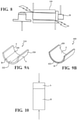
- Figures 9a and 9b illustrate bearings 310, 410 that can be made in similar manner.
- the embodiment of 9a shows a half shell bearing 310 of sintered powder metal material, wherein axially spaced end portions 320 are made of material A and middle portion 322 is made of material B and bridges the end portions 320.
- the materials A and B may be the same sintered powdered metal materials as those described above in connection with making a bushing, or may be different depending on the particular application.
- the axial regions represent localized environments of the bearing that would call for different materials as for reasons already explained in connection with the bushings above.
- the embodiment of Figure 9b is similar to 9a except that the layers 420, 422 are arranged radially (in a manner similar to the bushing 210 of Figure 3 ).
Landscapes
- Engineering & Computer Science (AREA)
- General Engineering & Computer Science (AREA)
- Mechanical Engineering (AREA)
- Chemical & Material Sciences (AREA)
- Materials Engineering (AREA)
- Metallurgy (AREA)
- Organic Chemistry (AREA)
- Manufacturing & Machinery (AREA)
- Composite Materials (AREA)
- Supercharger (AREA)
- Powder Metallurgy (AREA)
- Sliding-Contact Bearings (AREA)
Description
- This invention relates generally to powder metal sintered bushings and bearings for high temperature applications, such as 250 °C and above.
- Sintered powder metal bushings and bearings for high temperature applications such as turbochargers often see a wide range of temperatures and environments. For example, a given bushing may, in use, experience a very high temperature in one region of the bushing while being subjected to a considerably lower temperature in other regions. The same applies to wear, in which some portions are exposed to higher wear environments while other regions are exposed to relatively less wear. Traditionally, the bearing or bushing is designed as a compromise. A number of factors are taken into account and the appropriate material is selected to produce the bearing or bushing. These factors may include thermal and mechanical properties, oxidation and corrosion resistance, and wear resistance, over a wide range of temperatures. This may result in a portion of the bushing or bearing being subject to operating conditions for which the alloy composition is under-designed. Or, more commonly, the entire bushing or bearing has to be overdesigned in order to guarantee adequate performance in all the different operating conditions experienced along its length. Document
JPH07150913A - The invention is defined in the appended claims. The present disclosure provides a sintered powder metal bearing or bushing that has at least a first region made of a first alloy material and a second region made of a second alloy material different than that of the first.
- The bushing or bearing extends circumferentially and axially. If a bushing, it may be generally tubular with a generally cylindrical outer surface and a generally tubular inner surface and may extend axially between opposite ends. The first and second regions may be axially disposed relative to one another, such that the first region may be near one end of the bushing and the second region near the opposite end. The first end may represent a "hot" end of the bushing that is subject to high temperatures and the alloy used for the hot end is selected to be suitable for high temperature environments. The second end may represent a "cool" end of the bushing that is subject to lower temperatures and the alloy of the second region is different than the alloy of the first region and better suited for cool environments.
- Other arrangements are possible, wherein there may be three or more regions axially arranged relative to one another. For example, a bushing or bearing may experience more wear or higher mechanical stress near the opposite axial ends and may be formed from a first alloy that performs well under these conditions, whereas the second region axially between and separating the first regions may be formed of a second alloy different than the first alloy and better suited for the lower wear or lower stress environment of the middle portion of the bearing or bushing.
- The present disclosure also contemplates radial variations wherein, for example, a bushing may have high wear or temperature on an inner surface and lower wear or temperature on an outer surface, such that the radially inner first region layer is made from a first sintered powder metal alloy that performs well under high wear and/or temperature, and the radially outer second region layer is made from a second sintered powder metal layer that is better suited for lower temperature and/or wear.
- The present disclosure contemplates the alloy of one of the regions being selected as a high alloy iron and/or cobalt based material. High alloy preferably means having an alloy content >10wt% alloy elements by weight. The alloys may include, for example, a formulation based on 410L stainless steel. The present disclosure further contemplates higher alloy additions, wherein the alloy content may exceed 25wt% or even 30wt% by weight, such as a formulation based on 316 stainless steel. The alloy of the other region may have a lower alloy content than the first material, and a performance which may be suitable for the operating environment that this region of the bushing/bearing will see in use (e.g., different operating temperature and/or different mechanical stresses). Or the alloy of the other region may have a similar alloy content to the first material, but with a different combination of alloying elements to give performance better suited to that specific operating environment.
- The present disclosure contemplates making these multilayer bearing/bushings by a number of possible manufacturing techniques. One approach involves pressing different powders together (representative of the alloys of the first and second regions) into a combined compact, followed by sintering. Alternatively, the first and second regions could be compacted separately and then united during sintering, in a process commonly known as sinter bonding. This bonding could also be encouraged by the presence of a special active layer which brazes the parts together, in a process commonly called sinter brazing. Still another approach is to compact and sinter each of the first and second regions and then join them together by welding, for example friction welding.
- The multilayer materials enable the designer of the bushing or bearing to select the best material for each localized environment of the bushing or bearing, using different alloy formulations individually formulated for the different localized operating environments. For example, if a bushing for a particular application (e.g., turbocharger) was prone to hot end wear at temperatures >700°C, such a first end region is made from a high alloy sintered powder material that would correspond to an appropriate material for that condition. The opposite second end may be relatively cold in comparison, say <400°C, so this end region is made of a different high alloy sintered metal material formulated to give good performance in this specific operating environment. There may be a middle third region that may benefit from yet a different alloy and that could be employed and joined in situ or post sintering to the first and second regions. In the bushing example, the regions would preferably be axial but could be radial depending upon the application.
- One aspect of the invention provides a bushing comprising a body extending axially along a longitudinal axis between opposite ends and radially from an outer surface to an inner surface. The body includes a first material and a second material different from the first material. The first material is an iron-based material including 10 to 30 wt% Cr, 0 to 21 wt% Ni, 0 to 10 wt% Mo, 0 to 5 wt% W, 0 to 3 wt% C, 0 to 4 wt% V, 0 to 20 wt% Co, and Fe, based on the total weight of said first material. The second material is a cobalt based material.
- Herein is also disclosed a bushing comprising a body extending axially along a longitudinal axis between opposite ends and radially from an outer surface to an inner surface. The body includes a first material and a second material different from the first material, and the first and second materials are radially aligned.
- Yet another aspect of the invention provides a turbocharger presenting a bore and including a bushing, as defined above, disposed in the bore.
- Another aspect of the invention provides a method of manufacturing a bushing. The method comprises the step of joining a first material to a second material different from the first material, the first material being an iron-based material including 10 to 30 wt% Cr, 0 to 21 wt% Ni, 0 to 10 wt% Mo, 0 to 5 wt% W, 0 to 3 wt% C, 0 to 4 wt% V, 0 to 20 wt% Co, and Fe, based on the total weight of the first material and the second material being a cobalt based material.
- Herein is also disclosed a method of manufacturing a bushing, comprising the step of joining a first material to a second material different from the first material, wherein the second material is radially aligned with the first material.
- These and other features and advantages of the invention will be readily understood when considered in connection with the following detailed description and drawings, in which:
-
Figure 1 is a perspective view of a first embodiment of a multi-layer bushing; -
Figure 2 is a perspective view of a second embodiment of a multi-layer bushing; -
Figure 3 is a perspective view of a third embodiment of a multi-layer bushing; -
Figure 4 is a cross sectional view of the bushing ofFigure 1 taken along its longitudinal axis; -
Figure 5 is a cross sectional view of the bushing ofFigure 2 taken along its longitudinal axis; -
Figure 6 is a cross sectional view of the bushing ofFigure 3 taken along its longitudinal axis; -
Figure 7 is a schematic view of a turbocharger environment with a bushing installed, illustrating the temperature extremes typically experienced by the bushing along its axial length; -
Figure 8 is a schematic cross sectional view illustrating a bushing installed in an environment where variable loading and wear conditions are imparted to the bushing; -
Figures 9a and 9b are perspective views of alternative multi-layer bearing constructions showing axial and radial layers, respectively; -
Figure 10 is a schematic view illustrating multi-layer pressing of different powder metal alloy materials for making the bushings or bearings; -
Figures 11a-11c are schematic views illustrating sinter brazing of the axial multi-layer bushings and bearings; -
Figures 11d-11f are schematic views illustrating sinter bonding of the axial multi-layer bushings and bearings, with no special braze addition; -
Figures 11g - 11h are schematic views illustrating profiles that could be used to give easier alignment during assembly prior to sinter bonding or sinter brazing -
Figures 12a-b are schematic views illustrating friction welding of the axial multi-layer bushing or bearing. -
Figures 1 and4 illustrate a first embodiment of abushing 10. Thebushing 10 has a generally tubular shape with anouter surface 12 that is generally cylindrical and ininner surface 14 that is also generally cylindrical and spaced radially inward of theouter surface 12. Thebushing 10 extends axially along a longitudinal axis X between opposite ends 16, 18. One or both ends 16, 18 may be chamfered, or have other machined features present on the end faces and/or the outside diameter and/or the inside diameter. Thebushing 10 may be installed, for example, in aturbocharger 19 for an internal combustion engine as illustrated inFigure 7 . - The
bushing 10 is fabricated of sintered powdered metal of at least two different alloy materials. Thebushing 10 has a firstaxial portion 20 and a secondaxial portion 22. The first axial portion is made from a first sintered metal alloy of material A and the second portion is made from a second sintered metal alloy of material B that is of a different from that of material A in composition and/or properties. The first material A is an iron-based alloy and the second material B is a cobalt-based alloy. The alloys of materials A and B ofportions - As illustrated in
Figures 1 and4 , theportions bushing 10 may be of unequal length. The length of material A in thefirst portion 20 may range from 5-95% of the overall length of thebushing 10, with the material B of thesecond portion 22 occupying the balance. For example, material A could occupy about 25% and material B could occupy 75% of the overall length of thebushing 10. - A
bushing 10 of the type illustrated inFigures 1 and4 and described herein would have use in any application where different axial portions of thebushing 10 are under varying conditions when in use such that it would be desirable to have in one given axial region a sintered powdered metal material having a desired set of properties that would be best suited for that particular localized environment, and where in another axial portion of the bearing 10 it would be desirable to have a sintered powder material having different properties best suited for the other localized environment. One such example is bushings for turbocharger devices of the type used in internal combustion engine applications.Figure 7 shows a portion of theturbocharger 19 and thebushing 10 is shown installed in abore 24 of theturbocharger 19. Thisbushing 10 has an axial length of 25 mm. The lower end of thebushing 10 is exposed to the hot gases of the turbocharged environment and thus it sees a very high temperature, ranging from 500°C to about 800°C depending upon the particular turbocharger, application and usage. In comparison, the opposite upper end is isolated from the intense heat and sees temperatures ranging from about 300°C to 500°C. As such, in the span of 25 mm, the opposite end regions of thebushing 10 see a temperature swing differential of about 200°C to 300°C. It will be appreciated that sintered powder metal materials that would be suitable for an operating environment of 300-500°C at the lower temperature region of thebushing 10 would not necessarily perform as well at the higher temperature regions of 500°C to 800°C. In a typical design setting, the engineer would consider several factors, especially the maximum temperature, and select a single sintered metal material that would satisfy both environments. In other words, one may have to compromise on the selection of material, taking into account many local environmental factors and the associated performance of candidate materials. With the multi-layer axial bushing ofFigures 1 and4 , such compromises are substantially minimized. Instead of selecting the best compromise material that would suffice for all localized environments, one could look at the lower temperature region as the first axial portion of thebushing 10 and the higher temperature region as the second axial portion of the bushing and individually select the sintered powder metal material that is best suited for each specialized environment in the manufacture of thedual material bushing 10, as in the present embodiment. The material A for thefirst portion 20 is a different alloy than the material B for thesecond portion 22, but it is contemplated that, in some embodiments that are not part of the claimed invention, the materials may even be the same chemical composition but the microstructures may be substantially different to yield the desired different properties, depending upon the application involved. In the present invention, one selects a cobalt based material for one region of thebushing 10 and iron based material for another region of thebushing 10. The cobalt based material may be for the "hot" region of thebushing 10 and iron based material for the "cool" another region of thebushing 10. The cobalt based material could include 20 - 30 wt% Cr, 5 - 15 wt% Ni, 5 - 10 wt% W, and 0.5 - 1.5 wt% C as the main alloying elements. The iron based material could include 10 - 20 wt% Cr, 5 - 15 wt% Ni, 1 - 5 wt% Mo, and 1 - 2 w% C as the main alloying elements. The formulation of the cobalt based material is able to accommodate the localized high temperature operating environment, whereas the different composition of the iron based material is suitable for the localized low temperature operating environment. The beneficial properties of the cobalt based material that make it suitable for the hotter first axial portion include high-temperature wear resistance, and oxidation and corrosion resistance. The beneficial properties of the iron based material that make it suitable for the colder second axial portion include good mechanical and thermal properties together with sufficient wear resistance. It will be seen that properties of the desired material for the cooler region may not be a good choice for the hotter region since this material could suffer excessive oxidation or corrosion at high temperatures, and the high temperature wear resistance could also be inadequate leading to premature failure of the bushing component. - The materials for high temperature regions may be high alloy transition metals. These are preferably iron and/or cobalt based sintered powder metal alloys. By high alloy, it is meant that the content of the alloy addition to the iron and/or cobalt base is at least 10 wt%, more preferably at least 25 wt%, and may even exceed 35 wt%. The alloying elements may be incorporated as pre-alloyed in the main powder used in the pressing mix before sintering, or they may be incorporated as separate elements or master alloys mixed into the pressing mix before sintering, or a combination of any such techniques. During sintering, the alloying elements then become redistributed to give the desired sintered microstructure. Apart from the iron and/or cobalt, the other alloying elements preferably include:, 10 - 30 wt% Cr, 0 - 25 wt% Ni, 0 - 10 wt% Mo, 0 - 8 wt% W, 0 - 4 wt% V, 0.5 - 3.0 wt% C. Other alloying elements may also be present, depending on the specific operating environment.
- The iron based alloy or material includes a balance of iron. In other words, the remaining portion of the iron based alloy or material is formed of iron, so that the total contents of the alloy or material equal 100 wt %. The cobalt based alloy or material includes a balance of cobalt. In other words, the remaining portion of the cobalt based alloy or material is formed of cobalt, so that the total contents of the alloy or material equal 100 wt %.
- In one example iron based material, the principal alloying elements could be 15 - 25 wt% Cr, 0 - 5 wt% Ni, 1.5 - 6.5 wt% Mo, 1 - 4 wt% W, 1 - 3 wt% V, 0.5 - 2.5 wt% C. A more preferable composition is 18 - 24 wt% Cr, 0 - 5 wt% Ni, 1.5 - 6.5 wt% Mo, 1 - 4 wt% W, 1 - 3 wt% V, 0.8 - 2.4 wt% C.
- In one example iron based material, the principal alloying elements could be 10 - 25 wt% Cr, 7 - 20 wt% Ni, 1 - 7 wt% Mo, 0 - 3 wt% W, 0 - 3 wt% V, 0.5 - 3 wt% C. In this material, the high Ni content serves to improve high temperature properties such as oxidation resistance and wear resistance. A more preferable composition is 13 - 25 wt% Cr, 7- 20 wt% Ni, 1 - 7 wt% Mo, 0 - 2 wt% W, 0 - 2 wt% V, 1 - 3 wt% C.
- In one example iron based material, the principal alloying elements could be 10 - 25 wt% Cr, 10 - 21 wt% Ni, 2 - 10 wt% Mo, 0 - 3 wt% W, 0 - 2 wt% V, 4 - 20 wt% Co, 0.5 - 2 wt% C. In this material, the combination of high Ni and high Co contents serves to still further improve high temperature properties such as oxidation resistance and wear resistance. A more preferable composition is 13 - 25 wt% Cr, 10 - 21 wt% Ni, 2 - 10 wt% Mo, 0 - 3 wt% W, 0 - 2 wt% V, 4 - 20 wt% Co, 0.8 - 1.6 wt% C.
- In one example cobalt based material, the principal alloying elements could be 20 - 30 wt% Cr, 5 - 15 wt% Ni, 0 - 3 wt% Mo, 5 - 10 wt% W, 0 - 3 wt% V, 0.5 - 2 wt% C. In this material, use of the cobalt alloy matrix serves to still further improve high temperature properties such as oxidation resistance and wear resistance. A more preferable composition is 20 - 30 wt% Cr, 5 - 15 wt% Ni, 0 - 2 wt% Mo, 5 - 10 wt% W, 0 - 2 wt% V, 0.5 - 1.5 wt% C.
-
Figures 2 ,5 and8 illustrate another embodiment of amulti-axial layer bushing 110. The same reference numerals as used in connection with the first embodiment apply here except are offset by 100. This bushing includes three distinct axial regions wherein the sintered powder metal alloy material of each region is best suited for the localized environment associated with each region. It is noted that the three regions could all be different wherein three unique sintered powder metal alloys would be used. Or, as illustrated inFigure 8 , the regions at the ends of the bushing may have a common localized environment that is different than a middle region that separates the end regions. In the illustrated end use ofFigure 8 , thebushing 110 is shown supporting ashaft 28 that is side loaded, imparting uneven loading of thebushing 110 such that theaxial end portions 120 see a greater mechanical load and are thus subject to greater wear than themiddle portion 122. Knowing that thebushing 110 for this particular application will be subject to such a variable load/wear environment, thebushing 110 can be designed with theaxial end portions 120 fabricated in a different sintered powder metal alloy than that used for themiddle portion 122. As described above for the embodiment ofFigures 1 and4 , the different portions will have different alloy compositions and microstructure, and could also receive different process treatments (heat treatment, coatings, surface finish, etc.) to yield different properties. In most cases, the difference will include a variation in the composition of the alloys of the materials used for the various regions. For the illustrated end loading application ofFigure 8 , the material A of the high load/high end regions 120 would include materials that exhibit properties of high wear resistance under high mechanical load, such as an iron based alloy with 15 - 25 wt% Cr, 2 - 5 wt% Mo, 2 - 5 wt% W, 1 - 3 wt% V and 1.5 - 2.5 wt% C as the main alloying elements, whereas the material B selected for the low load/low wear middle region may be a lower alloy material that does not require such high load/wear properties, such as an iron based alloy with 10 - 15 wt% Cr and 0.5 - 1.5 wt% C as the main alloying elements. - There may be other applications where localized environments are encountered by the bushing, but instead of the environments being axially arranged, such as in a turbocharger or side load environment described above, the distinct environments are arranged in the radial direction of the bushing. In such cases, a bushing can be produced similar to above, but where the different portions are radially disposed instead of axially disposed. Such a
bushing 210 is illustrated schematically inFigures 3 and6 . In this example, theinner surface region 220 may experience higher loading or higher temperature or combinations thereof that would call for a high alloy powder metal sintered material, whereas a radiallyouter layer region 222 may see lower loading or lower temperatures or combinations thereof, that would call for a different sintered powdered metal alloy than that used for the innersurface radial region 220. In other applications, the critical feature of the innerradial region 220 may be its tribological compatibility with a shaft material or surface finish, rather than simply its ability to tolerate high temperatures and/or high mechanical loads. In this case, the outerradial region 222 may then be selected on the basis of its superior mechanical properties, where these are required to give mechanical support to the inner radial region. The same materials identified above in connection with the embodiments ofFigures 1-2 may be suitable for use in the layers of the radialmulti-layer bushing 210 ofFigures 3 and6 . - Different processes can be used to manufacture the bushings of
Figures 1-3 . -
Figure 10 illustrates a process wherein the different alloy powders of selected materials A and B are pressed concurrently in a first operation and then sintered as a single pressed part. This could be two, three or more layers and may be best suited for the axiallayered bushings layered bushings 210. -
Figures 11a-c illustrate an alternative process wherein theportions figures 11g-h . Sinter brazing could likewise be used for making the radiallayered bushings 210 and contoured features could similarly be added to assist with alignment ahead of sinter brazing. - Referring still to
Figures 11a-f , an alternative process is contemplated wherein theportions figures 11g-h . Sinter bonding could likewise be used for making the radiallayered bushings 210 and contoured features could similarly be added to assist with alignment ahead of sinter bonding. -
Figures 12a-b illustrate yet another process, wherein theportions layered bushings layered bushings 210. -
Figures 9a and 9b illustratebearings end portions 320 are made of material A andmiddle portion 322 is made of material B and bridges theend portions 320. The materials A and B may be the same sintered powdered metal materials as those described above in connection with making a bushing, or may be different depending on the particular application. The axial regions represent localized environments of the bearing that would call for different materials as for reasons already explained in connection with the bushings above. The embodiment ofFigure 9b is similar to 9a except that thelayers bushing 210 ofFigure 3 ). - The above description is exemplary of the present invention, the invention is defined by the appended claims.
Claims (15)
- A bushing (10; 110; 210), comprising:a body extending axially along a longitudinal axis between opposite ends (16, 18; 116, 118) and radially from an outer surface (12) to an inner surface (14),said body including a first material (A) and a second material (B) different from said first material, andsaid first material is an iron-based material including 10 to 30 wt% Cr, 0 to 21 wt% Ni, 0 to 10 wt% Mo, 0 to 5 wt% W, 0 to 3 wt% C, 0 to 4 wt% V, 0 to 20 wt% Co, and Fe, based on the total weight of said first materialcharacterised in that said second material (B) is a cobalt based material.
- A bushing (10; 110; 210) according to claim 1, wherein said first material (A) and said second material (B) are radially aligned or axially aligned.
- A bushing (10; 110; 210) according to claim 1, wherein said cobalt based material includes 10 to 30 wt% Cr, 5 to 21 wt% Ni, 0 to 10 wt% Mo, 0 to 10 wt% W, 0 to 3 wt% V, 0.5 to 3 wt% C, and Co, based on the total weight of said cobalt based material.
- A bushing (10; 110; 210) according to claim 1, wherein said cobalt based material includes 20 to 30 wt% Cr, 5 to 15 wt% Ni, 0 to 3 wt% Mo, 5 to 10 wt% W, 0 to 3 wt% V, 0.5 to 2 wt% C, and Co, based on the total weight of said cobalt based material.
- A bushing (10; 110; 210) according to claim 1, wherein said cobalt based material includes 20 to 30 wt% Cr, 5 to 15 wt% Ni, 0 to 2 wt% Mo, 5 to 10 wt% W, 0 to 2 wt% V, 0.5 to 1.5 wt% C, and Co, based on the total weight of said cobalt based material.
- A bushing (10; 110; 210) according to claim 1, wherein said cobalt based material includes 20 to 30 wt% Cr, 5 to 15 wt% Ni, 5 to 10 wt% W, and 0.5 to 1.5 wt% C, based on the total weight of said cobalt based material; and said iron based material includes 10 to 20 wt% Cr, 5 to 15 wt% Ni, 1 to 5 wt% Mo, and 1 to 2 w% C, based on the total weight of said iron based material.
- A bushing (10; 110; 210) according to claim 1, wherein said first material (A) includes 15 to 25 wt% Cr, 0 to 5 wt% Ni, 1.5 to 6.5 wt% Mo, 1 to 4 wt% W, 1 to 3 wt% V, and 0.5 to 2.5 wt% C, based on the total weight of said first material or wherein said first material (A) includes 18 to 24 wt% Cr, 0 to 5 wt% Ni, 1.5 to 6.5 wt% Mo, 1 to 4 wt% W, 1 to 3 wt% V, and 0.8 to 2.4 wt% C, based on the total weight of said first material.
- A bushing (10; 110; 210) according to claim 1, wherein said first material (A) includes 10 to 25 wt% Cr, 7 to 20 wt% Ni, 1 to 7 wt% Mo, 0 to 3 wt% W, 0 to 3 wt% V, and 0.5 to 3 wt% C, based on the total weight of said first material (A) or wherein said first material (A) includes 13 to 25 wt% Cr, 7 to 20 wt% Ni, 1 to 7 wt% Mo, 0 to 2 wt% W, 0 to 2 wt% V, and 1 to 3 wt% C, based on the total weight of said first material (A).
- A bushing (10; 110; 210) according to claim 1, wherein said first material (A) includes 10 to 25 wt% Cr, 10 to 21 wt% Ni, 2 to 10 wt% Mo, 0 to 3 wt% W, 0 to 2 wt% V, 4 to 20 wt% Co, and 0.5 to 2 wt% C, based on the total weight of said first material (A) or wherein said first material (A) includes 13 to 25 wt% Cr, 10 to 21 wt% Ni, 2 to 10 wt% Mo, 0 to 3 wt% W, 0 to 2 wt% V, 4 to 20 wt% Co, and 0.8 to 1.6 wt% C, based on the total weight of said first material (A).
- A bushing (10; 110; 210) according to claim 1, wherein said bushing has a tubular shape,said second material (B) including 10 to 30 wt% Cr, 5 to 21 wt% Ni, 0 to 10 wt% Mo, 0 to 10 wt% W, 0 to 3 wt% V, 0.5 to 3 wt% C, and Co, based on the total weight of said cobalt based material,said first (A) and second (B) materials are sintered powdered metal,said second material has a composition, microstructure and/or properties different from said first material, andsaid first material has an axial length ranging from 5 to 95% of the overall length of said bushing.
- A bushing (110) according to claim 1 including a third material different form said first material (A) and/or said second material (B).
- A turbocharger (19) presenting a bore and including a bushing (10; 110) according to any of claims 1 to 11 disposed in said bore.
- A method of manufacturing a bushing (10; 110; 210), comprising the step of:joining a first material (A) to a second material (B) different from the first material, the first material being an iron-based material including 10 to 30 wt% Cr, 0 to 21 wt% Ni, 0 to 10 wt% Mo, 0 to 5 wt% W, 0 to 3 wt% C, 0 to 4 wt% V, 0 to 20 wt% Co, and Fe, based on the total weight of the first material;characterised in that said second material (B) is a cobalt based material.
- A method according to claim 13, wherein the joining step includes pressing the first (A) and second (B) materials concurrently to form a single pressed part and sintering the single pressed part, or includes pressing the first and second materials separately and wherein the joining step includes sinter brazing the pressed first and second materials.
- A method according to claim 13 including pressing the first (A) and second (B) materials separately and wherein the joining step includes sinter bonding, or including pressing and sintering the first and second materials separately or wherein the joining step includes friction welding the sintered materials.
Applications Claiming Priority (3)
| Application Number | Priority Date | Filing Date | Title |
|---|---|---|---|
| US201762485581P | 2017-04-14 | 2017-04-14 | |
| US15/951,688 US10563695B2 (en) | 2017-04-14 | 2018-04-12 | Multi-layered sintered bushings and bearings |
| PCT/US2018/027414 WO2018191576A1 (en) | 2017-04-14 | 2018-04-13 | Multi-layer sintered bushings and bearings |
Publications (2)
| Publication Number | Publication Date |
|---|---|
| EP3610163A1 EP3610163A1 (en) | 2020-02-19 |
| EP3610163B1 true EP3610163B1 (en) | 2022-01-19 |
Family
ID=63792006
Family Applications (1)
| Application Number | Title | Priority Date | Filing Date |
|---|---|---|---|
| EP18721631.2A Active EP3610163B1 (en) | 2017-04-14 | 2018-04-13 | Multi-layer sintered bushings and bearings |
Country Status (7)
| Country | Link |
|---|---|
| US (1) | US10563695B2 (en) |
| EP (1) | EP3610163B1 (en) |
| JP (1) | JP7314054B2 (en) |
| KR (1) | KR20190137145A (en) |
| CN (1) | CN110621893B (en) |
| CA (1) | CA3059791A1 (en) |
| WO (1) | WO2018191576A1 (en) |
Families Citing this family (6)
| Publication number | Priority date | Publication date | Assignee | Title |
|---|---|---|---|---|
| US11209065B2 (en) * | 2017-08-09 | 2021-12-28 | Vibracoustic Usa, Inc. | Low torsion bushing and assembly |
| GB201908479D0 (en) * | 2019-06-13 | 2019-07-31 | Rolls Royce Plc | Joining method |
| US12017275B2 (en) * | 2020-08-24 | 2024-06-25 | Apple Inc. | Additive manufacturing methods for components |
| WO2022064980A1 (en) * | 2020-09-25 | 2022-03-31 | 国立大学法人大阪大学 | Friction pressure welding method |
| CN112502845A (en) * | 2020-11-30 | 2021-03-16 | 安庆帝伯格茨缸套有限公司 | Inner circle three-section type high-wear-resistance air-tightness cylinder sleeve |
| CN120591615B (en) * | 2025-07-14 | 2026-03-24 | Oppo广东移动通信有限公司 | Alloy materials and their preparation methods, structural components and electronic equipment |
Citations (1)
| Publication number | Priority date | Publication date | Assignee | Title |
|---|---|---|---|---|
| EP1412547B1 (en) * | 2001-07-03 | 2005-10-12 | Federal-Mogul Sintered Products Limited | Sintered tin-containing cobalt-based alloys |
Family Cites Families (31)
| Publication number | Priority date | Publication date | Assignee | Title |
|---|---|---|---|---|
| US2227307A (en) | 1939-03-02 | 1940-12-31 | Gen Motors Corp | Bearing structure |
| US2725265A (en) | 1951-11-26 | 1955-11-29 | Thompson Prod Inc | Valve stem guides |
| US2775024A (en) | 1953-05-29 | 1956-12-25 | Thompson Prod Inc | Powder metal multi-ring bushing |
| US4054449A (en) | 1970-12-04 | 1977-10-18 | Federal-Mogul Corporation | Process of making a composite heavy-duty powdered machine element |
| US3752003A (en) | 1970-12-04 | 1973-08-14 | Federal Mogul Corp | Composite heavy-duty machine element and method of making the same |
| US3770332A (en) | 1971-06-14 | 1973-11-06 | Federal Mogul Corp | Composite heavy-duty bushing and method of making the same |
| US3762881A (en) | 1971-06-14 | 1973-10-02 | Federal Mogul Corp | Composite high strength machine element and method of making the same |
| DE2139738C3 (en) | 1971-08-07 | 1974-03-07 | Deutsche Edelstahlwerke Gmbh, 4150 Krefeld | Sealing element |
| US4663241A (en) | 1980-09-08 | 1987-05-05 | United Technologies Corporation | Powder metal disk with selective fatigue strengthening |
| US4525178A (en) * | 1984-04-16 | 1985-06-25 | Megadiamond Industries, Inc. | Composite polycrystalline diamond |
| JPS63254221A (en) | 1987-04-10 | 1988-10-20 | Mitsubishi Electric Corp | Oil impregnated bearing |
| JPH07150913A (en) | 1993-11-30 | 1995-06-13 | Fuji Oozx Inc | Internal combustion engine valve guide and manufacturing method thereof |
| JP3191558B2 (en) * | 1994-04-08 | 2001-07-23 | 株式会社日立製作所 | Sliding structure and continuous hot metal plating equipment using it |
| US20050006006A1 (en) * | 2002-09-16 | 2005-01-13 | Gerald Schall | High temperature alloy particularly suitable for a long-life turbocharger nozzle ring |
| DK200201498A (en) * | 2002-10-07 | 2004-04-08 | Man B & W Diesel As | An atomizer for a fuel valve in a diesel engine, and a method for producing an atomizer |
| KR101149424B1 (en) | 2003-07-31 | 2012-05-25 | 가부시키가이샤 고마쓰 세이사쿠쇼 | Sintered sliding member and working implement-connecting apparatus |
| CN2783024Y (en) * | 2005-01-13 | 2006-05-24 | 巩立根 | Embedded slide thrust bearing |
| US20080146467A1 (en) | 2006-01-26 | 2008-06-19 | Takemori Takayama | Sintered Material, Ferrous Sintered Sliding Material, Producing Method of the Same, Sliding Member, Producing Method of the Same and Coupling Device |
| JP2008180295A (en) * | 2007-01-25 | 2008-08-07 | Nippon Densan Corp | Method of manufacturing bearing member, fluid dynamic pressure bearing device using bearing member manufactured by the method, spindle motor, and recording disk drive device |
| US8137747B2 (en) * | 2008-07-30 | 2012-03-20 | Honeywell International Inc. | Components, turbochargers, and methods of forming the components |
| KR101533458B1 (en) * | 2008-10-23 | 2015-07-03 | 두산인프라코어 주식회사 | Sliding bearing with improved wear resistance and method of manufacturing the same |
| JP2010215951A (en) | 2009-03-16 | 2010-09-30 | Hitachi Powdered Metals Co Ltd | Sintered composite sliding component and manufacturing method therefor |
| CN101592186B (en) * | 2009-07-10 | 2011-01-26 | 攀钢集团钢铁钒钛股份有限公司 | Bearing Bushing |
| CN101592187B (en) | 2009-07-10 | 2011-04-13 | 攀钢集团钢铁钒钛股份有限公司 | Axle bush and axle sleeve |
| US20120180747A1 (en) * | 2011-01-18 | 2012-07-19 | David Domanchuk | Thermal spray coating with a dispersion of solid lubricant particles |
| KR101989837B1 (en) | 2012-03-07 | 2019-06-17 | 엔티엔 가부시키가이샤 | Sintered bearing |
| US20160215820A1 (en) | 2013-09-10 | 2016-07-28 | Ntn Corporation | Sliding member and method for producing same |
| DE102013021059A1 (en) | 2013-12-18 | 2015-06-18 | Bleistahl-Produktions Gmbh & Co Kg. | Double / triple layer valve guide |
| US20170067472A1 (en) * | 2014-02-25 | 2017-03-09 | Borgwarner Inc. | Thrust bearing assembly including lined bearing surfaces |
| JP6461483B2 (en) * | 2014-04-04 | 2019-01-30 | Ntn株式会社 | Sintered bearing, fluid dynamic pressure bearing device including the same, and method for manufacturing sintered bearing |
| US20170045136A1 (en) | 2014-04-22 | 2017-02-16 | Ntn Corporation | Sintered mechanical component, device for forming powder compact, and method for forming powder compact |
-
2018
- 2018-04-12 US US15/951,688 patent/US10563695B2/en active Active
- 2018-04-13 EP EP18721631.2A patent/EP3610163B1/en active Active
- 2018-04-13 JP JP2019555910A patent/JP7314054B2/en active Active
- 2018-04-13 KR KR1020197033518A patent/KR20190137145A/en not_active Withdrawn
- 2018-04-13 WO PCT/US2018/027414 patent/WO2018191576A1/en not_active Ceased
- 2018-04-13 CN CN201880028698.4A patent/CN110621893B/en active Active
- 2018-04-13 CA CA3059791A patent/CA3059791A1/en not_active Abandoned
Patent Citations (1)
| Publication number | Priority date | Publication date | Assignee | Title |
|---|---|---|---|---|
| EP1412547B1 (en) * | 2001-07-03 | 2005-10-12 | Federal-Mogul Sintered Products Limited | Sintered tin-containing cobalt-based alloys |
Also Published As
| Publication number | Publication date |
|---|---|
| EP3610163A1 (en) | 2020-02-19 |
| US20180298947A1 (en) | 2018-10-18 |
| JP2020516773A (en) | 2020-06-11 |
| JP7314054B2 (en) | 2023-07-25 |
| WO2018191576A1 (en) | 2018-10-18 |
| CN110621893B (en) | 2021-07-13 |
| CN110621893A (en) | 2019-12-27 |
| CA3059791A1 (en) | 2018-10-18 |
| KR20190137145A (en) | 2019-12-10 |
| US10563695B2 (en) | 2020-02-18 |
Similar Documents
| Publication | Publication Date | Title |
|---|---|---|
| US10563695B2 (en) | Multi-layered sintered bushings and bearings | |
| US5654106A (en) | Sintered articles | |
| JPS60149703A (en) | Production of cam shaft | |
| US4556532A (en) | Method for manufacturing camshaft | |
| US6244161B1 (en) | High temperature-resistant material for articulated pistons | |
| WO2003022490A1 (en) | Forged in bushing article | |
| JP2017517399A (en) | Composite roll | |
| AT514296A1 (en) | Thermal spray application of plain bearing lining layer | |
| KR20230110837A (en) | Sliding member, bearing, manufacturing method of sliding member, manufacturing method of bearing | |
| EP3203098B1 (en) | Slide member and method for manufacturing same | |
| KR101231178B1 (en) | Method of Manufacturing A Composite Roll with Hardmetal Cemented Carbides for Rolling | |
| JP4200479B2 (en) | Cemented carbide roll for rolling | |
| JP3696666B2 (en) | Spherical sliding bearing | |
| JPH08159240A (en) | Gear and manufacturing method thereof | |
| JP6843509B2 (en) | Method for manufacturing composite parts having brass or bronze using a sintered fit | |
| JP2015513644A (en) | Connecting rod and manufacturing method thereof | |
| JP2019100350A (en) | Sliding member | |
| KR100205795B1 (en) | Valve lifter and its mamufacturing method of internal combustion engine | |
| JPS63227751A (en) | Fe sintered alloy synchronizing ring for transmission | |
| JP2008229647A (en) | Crankshaft and crankshaft manufacturing method | |
| JP6748018B2 (en) | Synchronizer ring | |
| JP2002301506A (en) | Composite roll made of sintered hard alloy | |
| JPS6132082Y2 (en) | ||
| JPS61104048A (en) | Sliding member and manufacture thereof | |
| KR20070084359A (en) | Sintered alloys for cam lobes and other high wear articles |
Legal Events
| Date | Code | Title | Description |
|---|---|---|---|
| STAA | Information on the status of an ep patent application or granted ep patent |
Free format text: STATUS: UNKNOWN |
|
| STAA | Information on the status of an ep patent application or granted ep patent |
Free format text: STATUS: THE INTERNATIONAL PUBLICATION HAS BEEN MADE |
|
| PUAI | Public reference made under article 153(3) epc to a published international application that has entered the european phase |
Free format text: ORIGINAL CODE: 0009012 |
|
| STAA | Information on the status of an ep patent application or granted ep patent |
Free format text: STATUS: REQUEST FOR EXAMINATION WAS MADE |
|
| 17P | Request for examination filed |
Effective date: 20191018 |
|
| AK | Designated contracting states |
Kind code of ref document: A1 Designated state(s): AL AT BE BG CH CY CZ DE DK EE ES FI FR GB GR HR HU IE IS IT LI LT LU LV MC MK MT NL NO PL PT RO RS SE SI SK SM TR |
|
| AX | Request for extension of the european patent |
Extension state: BA ME |
|
| DAV | Request for validation of the european patent (deleted) | ||
| DAX | Request for extension of the european patent (deleted) | ||
| REG | Reference to a national code |
Ref country code: DE Ref legal event code: R079 Ref document number: 602018029761 Country of ref document: DE Free format text: PREVIOUS MAIN CLASS: F16C0017240000 Ipc: B22F0005100000 |
|
| GRAP | Despatch of communication of intention to grant a patent |
Free format text: ORIGINAL CODE: EPIDOSNIGR1 |
|
| STAA | Information on the status of an ep patent application or granted ep patent |
Free format text: STATUS: GRANT OF PATENT IS INTENDED |
|
| RIC1 | Information provided on ipc code assigned before grant |
Ipc: B22F 5/10 20060101AFI20210317BHEP Ipc: B22F 7/06 20060101ALI20210317BHEP Ipc: B22F 7/08 20060101ALI20210317BHEP Ipc: C22C 1/04 20060101ALI20210317BHEP Ipc: C22C 38/44 20060101ALI20210317BHEP Ipc: C22C 38/46 20060101ALI20210317BHEP Ipc: C22C 38/52 20060101ALI20210317BHEP Ipc: F16C 33/24 20060101ALI20210317BHEP Ipc: F16C 33/12 20060101ALI20210317BHEP Ipc: F16C 33/14 20060101ALI20210317BHEP Ipc: F16C 17/24 20060101ALI20210317BHEP |
|
| INTG | Intention to grant announced |
Effective date: 20210407 |
|
| GRAJ | Information related to disapproval of communication of intention to grant by the applicant or resumption of examination proceedings by the epo deleted |
Free format text: ORIGINAL CODE: EPIDOSDIGR1 |
|
| STAA | Information on the status of an ep patent application or granted ep patent |
Free format text: STATUS: REQUEST FOR EXAMINATION WAS MADE |
|
| INTC | Intention to grant announced (deleted) | ||
| GRAP | Despatch of communication of intention to grant a patent |
Free format text: ORIGINAL CODE: EPIDOSNIGR1 |
|
| STAA | Information on the status of an ep patent application or granted ep patent |
Free format text: STATUS: GRANT OF PATENT IS INTENDED |
|
| INTG | Intention to grant announced |
Effective date: 20211019 |
|
| GRAS | Grant fee paid |
Free format text: ORIGINAL CODE: EPIDOSNIGR3 |
|
| GRAA | (expected) grant |
Free format text: ORIGINAL CODE: 0009210 |
|
| STAA | Information on the status of an ep patent application or granted ep patent |
Free format text: STATUS: THE PATENT HAS BEEN GRANTED |
|
| AK | Designated contracting states |
Kind code of ref document: B1 Designated state(s): AL AT BE BG CH CY CZ DE DK EE ES FI FR GB GR HR HU IE IS IT LI LT LU LV MC MK MT NL NO PL PT RO RS SE SI SK SM TR |
|
| REG | Reference to a national code |
Ref country code: GB Ref legal event code: FG4D |
|
| REG | Reference to a national code |
Ref country code: CH Ref legal event code: EP |
|
| REG | Reference to a national code |
Ref country code: DE Ref legal event code: R096 Ref document number: 602018029761 Country of ref document: DE |
|
| REG | Reference to a national code |
Ref country code: AT Ref legal event code: REF Ref document number: 1463495 Country of ref document: AT Kind code of ref document: T Effective date: 20220215 |
|
| REG | Reference to a national code |
Ref country code: IE Ref legal event code: FG4D |
|
| REG | Reference to a national code |
Ref country code: LT Ref legal event code: MG9D |
|
| REG | Reference to a national code |
Ref country code: NL Ref legal event code: MP Effective date: 20220119 |
|
| REG | Reference to a national code |
Ref country code: AT Ref legal event code: MK05 Ref document number: 1463495 Country of ref document: AT Kind code of ref document: T Effective date: 20220119 |
|
| PG25 | Lapsed in a contracting state [announced via postgrant information from national office to epo] |
Ref country code: NL Free format text: LAPSE BECAUSE OF FAILURE TO SUBMIT A TRANSLATION OF THE DESCRIPTION OR TO PAY THE FEE WITHIN THE PRESCRIBED TIME-LIMIT Effective date: 20220119 |
|
| PG25 | Lapsed in a contracting state [announced via postgrant information from national office to epo] |
Ref country code: SE Free format text: LAPSE BECAUSE OF FAILURE TO SUBMIT A TRANSLATION OF THE DESCRIPTION OR TO PAY THE FEE WITHIN THE PRESCRIBED TIME-LIMIT Effective date: 20220119 Ref country code: RS Free format text: LAPSE BECAUSE OF FAILURE TO SUBMIT A TRANSLATION OF THE DESCRIPTION OR TO PAY THE FEE WITHIN THE PRESCRIBED TIME-LIMIT Effective date: 20220119 Ref country code: PT Free format text: LAPSE BECAUSE OF FAILURE TO SUBMIT A TRANSLATION OF THE DESCRIPTION OR TO PAY THE FEE WITHIN THE PRESCRIBED TIME-LIMIT Effective date: 20220519 Ref country code: NO Free format text: LAPSE BECAUSE OF FAILURE TO SUBMIT A TRANSLATION OF THE DESCRIPTION OR TO PAY THE FEE WITHIN THE PRESCRIBED TIME-LIMIT Effective date: 20220419 Ref country code: LT Free format text: LAPSE BECAUSE OF FAILURE TO SUBMIT A TRANSLATION OF THE DESCRIPTION OR TO PAY THE FEE WITHIN THE PRESCRIBED TIME-LIMIT Effective date: 20220119 Ref country code: HR Free format text: LAPSE BECAUSE OF FAILURE TO SUBMIT A TRANSLATION OF THE DESCRIPTION OR TO PAY THE FEE WITHIN THE PRESCRIBED TIME-LIMIT Effective date: 20220119 Ref country code: ES Free format text: LAPSE BECAUSE OF FAILURE TO SUBMIT A TRANSLATION OF THE DESCRIPTION OR TO PAY THE FEE WITHIN THE PRESCRIBED TIME-LIMIT Effective date: 20220119 Ref country code: BG Free format text: LAPSE BECAUSE OF FAILURE TO SUBMIT A TRANSLATION OF THE DESCRIPTION OR TO PAY THE FEE WITHIN THE PRESCRIBED TIME-LIMIT Effective date: 20220419 |
|
| PG25 | Lapsed in a contracting state [announced via postgrant information from national office to epo] |
Ref country code: PL Free format text: LAPSE BECAUSE OF FAILURE TO SUBMIT A TRANSLATION OF THE DESCRIPTION OR TO PAY THE FEE WITHIN THE PRESCRIBED TIME-LIMIT Effective date: 20220119 Ref country code: LV Free format text: LAPSE BECAUSE OF FAILURE TO SUBMIT A TRANSLATION OF THE DESCRIPTION OR TO PAY THE FEE WITHIN THE PRESCRIBED TIME-LIMIT Effective date: 20220119 Ref country code: GR Free format text: LAPSE BECAUSE OF FAILURE TO SUBMIT A TRANSLATION OF THE DESCRIPTION OR TO PAY THE FEE WITHIN THE PRESCRIBED TIME-LIMIT Effective date: 20220420 Ref country code: FI Free format text: LAPSE BECAUSE OF FAILURE TO SUBMIT A TRANSLATION OF THE DESCRIPTION OR TO PAY THE FEE WITHIN THE PRESCRIBED TIME-LIMIT Effective date: 20220119 Ref country code: AT Free format text: LAPSE BECAUSE OF FAILURE TO SUBMIT A TRANSLATION OF THE DESCRIPTION OR TO PAY THE FEE WITHIN THE PRESCRIBED TIME-LIMIT Effective date: 20220119 |
|
| PG25 | Lapsed in a contracting state [announced via postgrant information from national office to epo] |
Ref country code: IS Free format text: LAPSE BECAUSE OF FAILURE TO SUBMIT A TRANSLATION OF THE DESCRIPTION OR TO PAY THE FEE WITHIN THE PRESCRIBED TIME-LIMIT Effective date: 20220519 |
|
| REG | Reference to a national code |
Ref country code: DE Ref legal event code: R097 Ref document number: 602018029761 Country of ref document: DE |
|
| PG25 | Lapsed in a contracting state [announced via postgrant information from national office to epo] |
Ref country code: SM Free format text: LAPSE BECAUSE OF FAILURE TO SUBMIT A TRANSLATION OF THE DESCRIPTION OR TO PAY THE FEE WITHIN THE PRESCRIBED TIME-LIMIT Effective date: 20220119 Ref country code: SK Free format text: LAPSE BECAUSE OF FAILURE TO SUBMIT A TRANSLATION OF THE DESCRIPTION OR TO PAY THE FEE WITHIN THE PRESCRIBED TIME-LIMIT Effective date: 20220119 Ref country code: RO Free format text: LAPSE BECAUSE OF FAILURE TO SUBMIT A TRANSLATION OF THE DESCRIPTION OR TO PAY THE FEE WITHIN THE PRESCRIBED TIME-LIMIT Effective date: 20220119 Ref country code: EE Free format text: LAPSE BECAUSE OF FAILURE TO SUBMIT A TRANSLATION OF THE DESCRIPTION OR TO PAY THE FEE WITHIN THE PRESCRIBED TIME-LIMIT Effective date: 20220119 Ref country code: DK Free format text: LAPSE BECAUSE OF FAILURE TO SUBMIT A TRANSLATION OF THE DESCRIPTION OR TO PAY THE FEE WITHIN THE PRESCRIBED TIME-LIMIT Effective date: 20220119 Ref country code: CZ Free format text: LAPSE BECAUSE OF FAILURE TO SUBMIT A TRANSLATION OF THE DESCRIPTION OR TO PAY THE FEE WITHIN THE PRESCRIBED TIME-LIMIT Effective date: 20220119 |
|
| PLBE | No opposition filed within time limit |
Free format text: ORIGINAL CODE: 0009261 |
|
| STAA | Information on the status of an ep patent application or granted ep patent |
Free format text: STATUS: NO OPPOSITION FILED WITHIN TIME LIMIT |
|
| PG25 | Lapsed in a contracting state [announced via postgrant information from national office to epo] |
Ref country code: AL Free format text: LAPSE BECAUSE OF FAILURE TO SUBMIT A TRANSLATION OF THE DESCRIPTION OR TO PAY THE FEE WITHIN THE PRESCRIBED TIME-LIMIT Effective date: 20220119 |
|
| REG | Reference to a national code |
Ref country code: CH Ref legal event code: PL |
|
| 26N | No opposition filed |
Effective date: 20221020 |
|
| REG | Reference to a national code |
Ref country code: BE Ref legal event code: MM Effective date: 20220430 |
|
| PG25 | Lapsed in a contracting state [announced via postgrant information from national office to epo] |
Ref country code: MC Free format text: LAPSE BECAUSE OF FAILURE TO SUBMIT A TRANSLATION OF THE DESCRIPTION OR TO PAY THE FEE WITHIN THE PRESCRIBED TIME-LIMIT Effective date: 20220119 Ref country code: LU Free format text: LAPSE BECAUSE OF NON-PAYMENT OF DUE FEES Effective date: 20220413 Ref country code: LI Free format text: LAPSE BECAUSE OF NON-PAYMENT OF DUE FEES Effective date: 20220430 Ref country code: CH Free format text: LAPSE BECAUSE OF NON-PAYMENT OF DUE FEES Effective date: 20220430 |
|
| PG25 | Lapsed in a contracting state [announced via postgrant information from national office to epo] |
Ref country code: SI Free format text: LAPSE BECAUSE OF FAILURE TO SUBMIT A TRANSLATION OF THE DESCRIPTION OR TO PAY THE FEE WITHIN THE PRESCRIBED TIME-LIMIT Effective date: 20220119 Ref country code: BE Free format text: LAPSE BECAUSE OF NON-PAYMENT OF DUE FEES Effective date: 20220430 |
|
| PG25 | Lapsed in a contracting state [announced via postgrant information from national office to epo] |
Ref country code: IE Free format text: LAPSE BECAUSE OF NON-PAYMENT OF DUE FEES Effective date: 20220413 |
|
| P01 | Opt-out of the competence of the unified patent court (upc) registered |
Effective date: 20230528 |
|
| PG25 | Lapsed in a contracting state [announced via postgrant information from national office to epo] |
Ref country code: MK Free format text: LAPSE BECAUSE OF FAILURE TO SUBMIT A TRANSLATION OF THE DESCRIPTION OR TO PAY THE FEE WITHIN THE PRESCRIBED TIME-LIMIT Effective date: 20220119 Ref country code: CY Free format text: LAPSE BECAUSE OF FAILURE TO SUBMIT A TRANSLATION OF THE DESCRIPTION OR TO PAY THE FEE WITHIN THE PRESCRIBED TIME-LIMIT Effective date: 20220119 |
|
| PG25 | Lapsed in a contracting state [announced via postgrant information from national office to epo] |
Ref country code: HU Free format text: LAPSE BECAUSE OF FAILURE TO SUBMIT A TRANSLATION OF THE DESCRIPTION OR TO PAY THE FEE WITHIN THE PRESCRIBED TIME-LIMIT; INVALID AB INITIO Effective date: 20180413 |
|
| PG25 | Lapsed in a contracting state [announced via postgrant information from national office to epo] |
Ref country code: MT Free format text: LAPSE BECAUSE OF FAILURE TO SUBMIT A TRANSLATION OF THE DESCRIPTION OR TO PAY THE FEE WITHIN THE PRESCRIBED TIME-LIMIT Effective date: 20220119 |
|
| PGFP | Annual fee paid to national office [announced via postgrant information from national office to epo] |
Ref country code: DE Payment date: 20250319 Year of fee payment: 8 |
|
| REG | Reference to a national code |
Ref country code: GB Ref legal event code: 732E Free format text: REGISTERED BETWEEN 20250911 AND 20250917 |
|
| PG25 | Lapsed in a contracting state [announced via postgrant information from national office to epo] |
Ref country code: TR Free format text: LAPSE BECAUSE OF FAILURE TO SUBMIT A TRANSLATION OF THE DESCRIPTION OR TO PAY THE FEE WITHIN THE PRESCRIBED TIME-LIMIT Effective date: 20220119 |
|
| REG | Reference to a national code |
Ref country code: DE Ref legal event code: R081 Ref document number: 602018029761 Country of ref document: DE Owner name: FEDERAL-MOGUL POWERTRAIN LLC (N. D. GES. D. ST, US Free format text: FORMER OWNER: TENNECO INC, LAKE FOREST, IL, US |
|
| PGFP | Annual fee paid to national office [announced via postgrant information from national office to epo] |
Ref country code: GB Payment date: 20260319 Year of fee payment: 9 |
|
| PGFP | Annual fee paid to national office [announced via postgrant information from national office to epo] |
Ref country code: IT Payment date: 20260319 Year of fee payment: 9 |
|
| PGFP | Annual fee paid to national office [announced via postgrant information from national office to epo] |
Ref country code: FR Payment date: 20260320 Year of fee payment: 9 |