EP1412547B1 - Sintered tin-containing cobalt-based alloys - Google Patents
Sintered tin-containing cobalt-based alloys Download PDFInfo
- Publication number
- EP1412547B1 EP1412547B1 EP02782469A EP02782469A EP1412547B1 EP 1412547 B1 EP1412547 B1 EP 1412547B1 EP 02782469 A EP02782469 A EP 02782469A EP 02782469 A EP02782469 A EP 02782469A EP 1412547 B1 EP1412547 B1 EP 1412547B1
- Authority
- EP
- European Patent Office
- Prior art keywords
- weight
- powder
- solid lubricant
- tin
- cobalt
- Prior art date
- Legal status (The legal status is an assumption and is not a legal conclusion. Google has not performed a legal analysis and makes no representation as to the accuracy of the status listed.)
- Expired - Lifetime
Links
Images
Classifications
-
- F—MECHANICAL ENGINEERING; LIGHTING; HEATING; WEAPONS; BLASTING
- F16—ENGINEERING ELEMENTS AND UNITS; GENERAL MEASURES FOR PRODUCING AND MAINTAINING EFFECTIVE FUNCTIONING OF MACHINES OR INSTALLATIONS; THERMAL INSULATION IN GENERAL
- F16C—SHAFTS; FLEXIBLE SHAFTS; ELEMENTS OR CRANKSHAFT MECHANISMS; ROTARY BODIES OTHER THAN GEARING ELEMENTS; BEARINGS
- F16C33/00—Parts of bearings; Special methods for making bearings or parts thereof
- F16C33/02—Parts of sliding-contact bearings
- F16C33/04—Brasses; Bushes; Linings
- F16C33/06—Sliding surface mainly made of metal
- F16C33/12—Structural composition; Use of special materials or surface treatments, e.g. for rust-proofing
- F16C33/121—Use of special materials
-
- C—CHEMISTRY; METALLURGY
- C22—METALLURGY; FERROUS OR NON-FERROUS ALLOYS; TREATMENT OF ALLOYS OR NON-FERROUS METALS
- C22C—ALLOYS
- C22C1/00—Making non-ferrous alloys
- C22C1/04—Making non-ferrous alloys by powder metallurgy
- C22C1/0433—Nickel- or cobalt-based alloys
-
- C—CHEMISTRY; METALLURGY
- C22—METALLURGY; FERROUS OR NON-FERROUS ALLOYS; TREATMENT OF ALLOYS OR NON-FERROUS METALS
- C22C—ALLOYS
- C22C32/00—Non-ferrous alloys containing at least 5% by weight but less than 50% by weight of oxides, carbides, borides, nitrides, silicides or other metal compounds, e.g. oxynitrides, sulfides, whether added as such or formed in situ
- C22C32/0089—Non-ferrous alloys containing at least 5% by weight but less than 50% by weight of oxides, carbides, borides, nitrides, silicides or other metal compounds, e.g. oxynitrides, sulfides, whether added as such or formed in situ with other, not previously mentioned inorganic compounds as the main non-metallic constituent, e.g. sulfides, glass
-
- F—MECHANICAL ENGINEERING; LIGHTING; HEATING; WEAPONS; BLASTING
- F01—MACHINES OR ENGINES IN GENERAL; ENGINE PLANTS IN GENERAL; STEAM ENGINES
- F01D—NON-POSITIVE DISPLACEMENT MACHINES OR ENGINES, e.g. STEAM TURBINES
- F01D25/00—Component parts, details, or accessories, not provided for in, or of interest apart from, other groups
- F01D25/16—Arrangement of bearings; Supporting or mounting bearings in casings
- F01D25/166—Sliding contact bearing
-
- F—MECHANICAL ENGINEERING; LIGHTING; HEATING; WEAPONS; BLASTING
- F01—MACHINES OR ENGINES IN GENERAL; ENGINE PLANTS IN GENERAL; STEAM ENGINES
- F01D—NON-POSITIVE DISPLACEMENT MACHINES OR ENGINES, e.g. STEAM TURBINES
- F01D5/00—Blades; Blade-carrying members; Heating, heat-insulating, cooling or antivibration means on the blades or the members
- F01D5/12—Blades
- F01D5/28—Selecting particular materials; Particular measures relating thereto; Measures against erosion or corrosion
-
- B—PERFORMING OPERATIONS; TRANSPORTING
- B22—CASTING; POWDER METALLURGY
- B22F—WORKING METALLIC POWDER; MANUFACTURE OF ARTICLES FROM METALLIC POWDER; MAKING METALLIC POWDER; APPARATUS OR DEVICES SPECIALLY ADAPTED FOR METALLIC POWDER
- B22F2998/00—Supplementary information concerning processes or compositions relating to powder metallurgy
- B22F2998/10—Processes characterised by the sequence of their steps
-
- F—MECHANICAL ENGINEERING; LIGHTING; HEATING; WEAPONS; BLASTING
- F05—INDEXING SCHEMES RELATING TO ENGINES OR PUMPS IN VARIOUS SUBCLASSES OF CLASSES F01-F04
- F05C—INDEXING SCHEME RELATING TO MATERIALS, MATERIAL PROPERTIES OR MATERIAL CHARACTERISTICS FOR MACHINES, ENGINES OR PUMPS OTHER THAN NON-POSITIVE-DISPLACEMENT MACHINES OR ENGINES
- F05C2201/00—Metals
- F05C2201/04—Heavy metals
- F05C2201/0433—Iron group; Ferrous alloys, e.g. steel
- F05C2201/0463—Cobalt
-
- F—MECHANICAL ENGINEERING; LIGHTING; HEATING; WEAPONS; BLASTING
- F05—INDEXING SCHEMES RELATING TO ENGINES OR PUMPS IN VARIOUS SUBCLASSES OF CLASSES F01-F04
- F05C—INDEXING SCHEME RELATING TO MATERIALS, MATERIAL PROPERTIES OR MATERIAL CHARACTERISTICS FOR MACHINES, ENGINES OR PUMPS OTHER THAN NON-POSITIVE-DISPLACEMENT MACHINES OR ENGINES
- F05C2201/00—Metals
- F05C2201/04—Heavy metals
- F05C2201/0433—Iron group; Ferrous alloys, e.g. steel
- F05C2201/0466—Nickel
-
- F—MECHANICAL ENGINEERING; LIGHTING; HEATING; WEAPONS; BLASTING
- F05—INDEXING SCHEMES RELATING TO ENGINES OR PUMPS IN VARIOUS SUBCLASSES OF CLASSES F01-F04
- F05D—INDEXING SCHEME FOR ASPECTS RELATING TO NON-POSITIVE-DISPLACEMENT MACHINES OR ENGINES, GAS-TURBINES OR JET-PROPULSION PLANTS
- F05D2220/00—Application
- F05D2220/40—Application in turbochargers
-
- F—MECHANICAL ENGINEERING; LIGHTING; HEATING; WEAPONS; BLASTING
- F05—INDEXING SCHEMES RELATING TO ENGINES OR PUMPS IN VARIOUS SUBCLASSES OF CLASSES F01-F04
- F05D—INDEXING SCHEME FOR ASPECTS RELATING TO NON-POSITIVE-DISPLACEMENT MACHINES OR ENGINES, GAS-TURBINES OR JET-PROPULSION PLANTS
- F05D2240/00—Components
- F05D2240/50—Bearings
-
- F—MECHANICAL ENGINEERING; LIGHTING; HEATING; WEAPONS; BLASTING
- F05—INDEXING SCHEMES RELATING TO ENGINES OR PUMPS IN VARIOUS SUBCLASSES OF CLASSES F01-F04
- F05D—INDEXING SCHEME FOR ASPECTS RELATING TO NON-POSITIVE-DISPLACEMENT MACHINES OR ENGINES, GAS-TURBINES OR JET-PROPULSION PLANTS
- F05D2300/00—Materials; Properties thereof
- F05D2300/10—Metals, alloys or intermetallic compounds
- F05D2300/13—Refractory metals, i.e. Ti, V, Cr, Zr, Nb, Mo, Hf, Ta, W
- F05D2300/132—Chromium
-
- F—MECHANICAL ENGINEERING; LIGHTING; HEATING; WEAPONS; BLASTING
- F16—ENGINEERING ELEMENTS AND UNITS; GENERAL MEASURES FOR PRODUCING AND MAINTAINING EFFECTIVE FUNCTIONING OF MACHINES OR INSTALLATIONS; THERMAL INSULATION IN GENERAL
- F16C—SHAFTS; FLEXIBLE SHAFTS; ELEMENTS OR CRANKSHAFT MECHANISMS; ROTARY BODIES OTHER THAN GEARING ELEMENTS; BEARINGS
- F16C2360/00—Engines or pumps
- F16C2360/23—Gas turbine engines
- F16C2360/24—Turbochargers
Definitions
- the present invention relates to alloys based on cobalt and a method for the production thereof by a powder metallurgy route.
- Turbochargers for internal combustion engines have been in common use for many years in order to increase the power output and decrease the emissions of an engine.
- one drawback with the use of turbochargers has been the so-called “turbo lag" where the engine speed response to the throttle is delayed owing to the time needed for the exhaust gas turbine to increase speed and hence supply further air by the compressor for combustion.
- turbocharger designs have been introduced which have largely overcome or at least greatly reduced the turbo lag problem.
- variable geometry devices Both types of design may be broadly described as variable geometry devices.
- Turbochargers are used on both gasoline and diesel oil fuelled vehicles. Generally, turbochargers for gasoline engines run at a higher temperature than do turbochargers for diesel oil fuelled vehicles. Furthermore, due to the superior fuel efficiency of diesel engines, there is an increasing drive to employ turbocharged diesel engines in mass produced "family" type vehicles. Effectively, such diesel powered vehicles are intended to drive and behave in a manner substantially indistinguishable from gasoline fuelled vehicles including the performance thereof.
- turbochargers in gasoline engines run at a higher temperature than those for diesel engines and furthermore, the general temperature levels for both types are rising as overall engine performance increases.
- the unlubricated bearing or bush is primarily required to have good oxidation resistance at its operating temperature rather than high creep resistance, as required in rotating parts such as blades for gas turbine engines, for example. Furthermore, internal defects such as relatively high levels of porosity, prior particle boundaries and grain boundary precipitates may be allowable.
- a sintered material consisting of one or more cobalt-based alloys each having a composition in weight%: Cr 5-30/Mo 0-15/Ni 0-25/W 0-15/C 0-5/Si 0-5/B 0-5/Fe 0-5/Mn 0-5/total others 10max/Co balance, from 3-15 weight% of Sn; and from 1-6 weight% of a solid lubricant material.
- the “total other” elements in the cobalt-based alloy may include Cu, V, Nb, Al and Ta.
- the solid lubricant may comprise molybdenum disulphide and/or tungsten disulphide for example.
- the material according to the first aspect of the present invention may also possess up to 10 vol% of porosity.
- the tin content lies in the range from 4 to 10 weight%.
- tin content acts as a powder pressing aid, acting as a die and powder particle lubricant thus, enabling higher green densities and hence strengths to be achieved at any given pressing pressure.
- the solid lubricant may include molybdenum disulphide and/or tungsten disulphide, however, any solid lubricant powder known to be effective at high operating temperatures and able to withstand the sintering step may be employed.
- the material and method of the present invention employ a so-called dry lubricating material such as tungsten disulphide or molybdenum disulphide; firstly, because the service applications intended for the materials are in high-temperature environments where conventional oil lubrication is not possible and, secondly because the sulphur content of these materials appears to have a beneficial effect on their production.
- the tungsten and/or molybdenum disulphide phase partially dissociates at the sintering temperature, and under the ambient conditions of a gas sintering atmosphere at substantially atmospheric pressure, liberating some free sulphur which, in the presence of liquid tin, seems to promote the diffusion of cobalt through the structure as evidenced by SEM EDAX analysis. Tin has been found deep inside prior cobalt alloy particles and substantial amounts of cobalt in the once-liquid phase.
- a preferred range of solid lubricant may lie in the range from 2 to 4 weight%.
- tin powder is mixed with the cobalt-based powder to provide liquid phase sintering, the tin having the effect of producing a liquid phase at a sintering temperature of 1170°C and below and also using conventional high-volume production equipment such as continuous throughput conveyor furnaces and the like.
- Such furnaces may be mesh belt or walking beam furnaces, for example, and utilise flowing protective or reducing gas atmospheres comprising hydrogen and nitrogen mixtures, for example, at substantially atmospheric pressure.
- Such furnaces generally have a maximum operating temperature capability of about 1200°C.
- batch furnaces using vacuum or gas atmospheres may be used if desired.
- the liquid phase serves to promote diffusion and consequent densification of the pressed article.
- the initial liquid tin phase reacts with the cobalt-based alloy and diffuses into the green pressing and is itself eventually absorbed into the solid by reaction therewith so as to produce a rigid skeleton of re-arranged prior particles with a once-liquid phase filling the spaces of the skeleton. Inter-particle-necking between the prior particles is produced.
- Liquid phase forms as the tin melts at around 232°C on heating to the sintering temperature.
- the liquid tin becomes enriched in cobalt as heating progresses until the final sintering temperature is reached, leaving a volume fraction of liquid proportional to the original mass fraction of tin added..
- the liquid solidifies eutectically on cooling at around 1112°C.
- At least a proportion of the cobalt-based powder be of irregular particle shape. Where all of the powder is of substantially regular shape, such as rounded particles for example, it is not possible to achieve sufficient green strength to permit handling and survive die-ejection.
- pre-alloyed cobalt-based pre-alloyed powder may be mixed together in the same powder mixture prior to compaction and sintering. Additionally or alternatively there may be a proportion of one powder having irregularly shaped particles and a proportion of the same or a different pre-alloyed powder composition having regular shaped powder particles.
- turbocharger casing In the types of turbocharger applications intended but, to which are by no means limited, bushings and bearings are frequently located and held in place by the turbocharger casing (often being in a cast iron material which is cast about the bearing or other part) thereby lending considerable mechanical strength thereto.
- alloys Whilst it is entirely possible and feasible to use an alloy specifically tailored to a particular service application, it is preferred to use commercially available "off the shelf" cobalt-based to further control production costs.
- Such alloys are manufactured by companies such as INCO (trade name), Deloro-Stellite (trade name), Metco (trade name) company, Haynes (trade name) and others, for example. Such alloys produced by these companies are used for the applications as described above (HIPped) and also for hard-facing, oxidation resistant uses and applied, for example, by plasma spraying and the like. Examples of such commercially available alloys may include Stellite 31 (trade name), Tribaloy T-400 (trade name) and Metco 45VF-NS (trade name).
- the present invention provides both a material, and a method for the production thereof, able to withstand the intended service environment and able to be produced in high volumes on existing high volume production plant at an economic cost unlike prior art cobalt-based materials.
- a bearing for a turbocharger when made of the material of the first aspect of the present invention.
- a bearing for a turbocharger when made by the method of the second aspect of the present invention.
- Atomised powder of Tribaloy T-400 (trade name) was mixed for 20 minutes in a Y-cone blender with 10wt% of tin powder and 3.5wt% of molybdenum disulphide powder. 1.5wt% of a fugitive die lubricant, Kenolube (trade name), was also added.
- the blended powder was uniaxially cold pressed at 770 MPa and sintered in a walking beam furnace for approximately 15 minutes at 1170°C with an atmosphere of 90% nitrogen: 10% hydrogen. Visual and SEM-EDAX analysis revealed that original particle boundaries are not visible and particle shape cannot be determined.
- the microstructure consisted of Co-Mo-Cr particles approximately 12 microns in diameter in a matrix of Co-Mo-Cr-Sn, with a Co-Sn-Mo-Cr phase at particle boundaries having the appearance of solidified liquid.
- a Cr-S phase was present as a discrete 10 micron sized phase.
- Atomised powder of Metco 45VF-NS (trade name) was mixed for 20 minutes in a Y-cone blender with 5wt% of tin powder and 2wt% of molybdenum disulphide powder. 1.5wt% of Kenolube (trade name) die lubricant was also added.
- the blended powder was uniaxially cold pressed at 770MPa and sintered in a walking beam furnace for approximately 15 minutes at 1170°C with an atmosphere of 90% nitrogen: 10% hydrogen.
- Visual and SEM-EDAX analysis revealed that original particle shape can be determined with particles having the composition Co-Cr-Ni-W-Sn.
- Inter-particle bonding had taken place the boundaries having 5 micron sized precipitates of Cr-Co-W-Ni-Mo and Cr-S-Sn-Co-Ni, with a Sn-Ni-Co-Cr phase having the appearance of solidified liquid. Within the particles there were 5 micron precipitates of Cr-Co-W-Ni-Mo.
- Atomised powder Stellite 31 (trade name) was mixed for 20 minutes in Y-cone blender with 7.5wt% of tin powder and 3.5wt% of molybdenum disulphide powder. 1.5wt% of Kenolube (trade name) die lubricant was also added. The blended powder was uniaxially cold pressed at 770MPa and sintered in a walking beam furnace for approximately 15 minutes at 1170°C with an atmosphere of 90% nitrogen: 10% hydrogen. Visual and SEM-EDAX analysis revealed that original particle boundaries were visible due to the formation of precipitates.
- the particles were composed of Co-Cr-Ni-W-Fe-Sn and the precipitates were a mixture of Cr-S and Cr-W-Co-Mo, with a Sn-Ni-Co-Cr phase having the appearance of solidified liquid.
- Atomised powder Stellite 31 (trade name) was mixed for 20 minutes in Y-cone blender with 7.5wt% of tin powder and 3.5wt% of tungsten disulphide powder. 1.5wt% of Kenolube (trade name) die lubricant was also added. The blended powder was uniaxially cold pressed at 770MPa and sintered in a walking beam furnace for approximately 15 minutes at 1170°C with an atmosphere of 90% nitrogen: 10% hydrogen. Visual and SEM-EDAX analysis revealed that original particle boundaries were visible due to the formation of precipitates.
- the particles were composed of Co-Cr-Ni-W-Fe-Sn and the precipitates were a mixture of Cr-S and Cr-W-Co-Mo, with a Sn-Ni-Co-Cr phase having the appearance of solidified liquid.
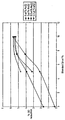
- the drawing shows a graph of percentage shrinkage of the overall diameter (OD).
- tin powder blended with the respective cobalt alloy powder which, in all cases, is Stellite 31 (trade name).
- Stellite 31 (trade name)
- the Stellite 31 powder has been blended with the appropriate amount of tin powder and also the stipulated amount of molybdenum disulphide or tungsten disulphide according to the legend.
- the Stellite 31 powder was mixed with the appropriate amount of tin and molybdenum-disulphide or tungsten-disulphide, together with 1.5wt% of Kenolube (trade name), as a die lubricant.
- the sulphur can also promote formation of liquid with Co in a similar fashion to Sn. It is believed that once the tin content reaches about 10wt%, then the quantity of liquid phase present is sufficient to promote diffusion and densification without the need for the sulphur containing solid lubricant compound in this regard. However, it is believed that the presence of such a solid lubricant compound in the structure assists the bearing sliding characteristics in the application, especially where the presence of a conventional liquid lubricant is not possible.
Abstract
Description
- The present invention relates to alloys based on cobalt and a method for the production thereof by a powder metallurgy route.
- Turbochargers for internal combustion engines have been in common use for many years in order to increase the power output and decrease the emissions of an engine. However, one drawback with the use of turbochargers has been the so-called "turbo lag" where the engine speed response to the throttle is delayed owing to the time needed for the exhaust gas turbine to increase speed and hence supply further air by the compressor for combustion. In recent years, however, turbocharger designs have been introduced which have largely overcome or at least greatly reduced the turbo lag problem.
- Reduction in turbo lag has generally been achieved in one of two main ways. Firstly, there are designs which have moving vanes in order to alter the approach gas speed and direction on to the exhaust turbine to utilise the exhaust gas flow more efficiently at low turbine speeds and hence enable the compressor impeller wheel to accelerate more rapidly in response to throttle demand. Such designs are complex and hence very costly to manufacture. Secondly, there are designs which alter the volume of the exhaust gas passage in the turbocharger casing thus, influencing the exhaust gas velocity and again enabling the exhaust driven compressor to accelerate more rapidly in response to throttle demand.
- Both types of design may be broadly described as variable geometry devices.
- Turbochargers are used on both gasoline and diesel oil fuelled vehicles. Generally, turbochargers for gasoline engines run at a higher temperature than do turbochargers for diesel oil fuelled vehicles. Furthermore, due to the superior fuel efficiency of diesel engines, there is an increasing drive to employ turbocharged diesel engines in mass produced "family" type vehicles. Effectively, such diesel powered vehicles are intended to drive and behave in a manner substantially indistinguishable from gasoline fuelled vehicles including the performance thereof.
- As noted above, turbochargers in gasoline engines run at a higher temperature than those for diesel engines and furthermore, the general temperature levels for both types are rising as overall engine performance increases.
- Unlubricated bearings and components in contact with the exhaust gas for use in turbochargers must be able to survive at 1050°C without significant oxidation. Consequently, the alloys available for such applications tend to be relatively very expensive cobalt-based or nickel-based alloys made by investment casting or hot isostatic pressing (HIP) full densification with mechanical properties and surface degradation resistance more applicable to high-cost, critical components in aircraft gas turbine engines, for example. Components made by these production processes are very expensive and have performance parameters in excess of that required in, for example, bearings for turbocharger applications.
- In the modern types of turbocharger described above, the unlubricated bearing or bush is primarily required to have good oxidation resistance at its operating temperature rather than high creep resistance, as required in rotating parts such as blades for gas turbine engines, for example. Furthermore, internal defects such as relatively high levels of porosity, prior particle boundaries and grain boundary precipitates may be allowable.
- It is an object of the present invention to provide a material and method for the processing thereof suitable for use as an unlubricated bearing and/or bush in a turbocharger at an economic production cost.
- According to a first aspect of the present invention there is provided a sintered material, the material consisting of one or more cobalt-based alloys each having a composition in weight%: Cr 5-30/Mo 0-15/Ni 0-25/W 0-15/C 0-5/Si 0-5/B 0-5/Fe 0-5/Mn 0-5/total others 10max/Co balance, from 3-15 weight% of Sn; and from 1-6 weight% of a solid lubricant material.
- The "total other" elements in the cobalt-based alloy may include Cu, V, Nb, Al and Ta.
- The solid lubricant may comprise molybdenum disulphide and/or tungsten disulphide for example.
- The material according to the first aspect of the present invention may also possess up to 10 vol% of porosity.
- According to a second aspect of the present invention, there is provided a method according to
claim 7. - It is preferred that the tin content lies in the range from 4 to 10 weight%.
- An unexpected advantage of the tin content is that it acts as a powder pressing aid, acting as a die and powder particle lubricant thus, enabling higher green densities and hence strengths to be achieved at any given pressing pressure.
- The solid lubricant may include molybdenum disulphide and/or tungsten disulphide, however, any solid lubricant powder known to be effective at high operating temperatures and able to withstand the sintering step may be employed.
- The material and method of the present invention employ a so-called dry lubricating material such as tungsten disulphide or molybdenum disulphide; firstly, because the service applications intended for the materials are in high-temperature environments where conventional oil lubrication is not possible and, secondly because the sulphur content of these materials appears to have a beneficial effect on their production. The tungsten and/or molybdenum disulphide phase partially dissociates at the sintering temperature, and under the ambient conditions of a gas sintering atmosphere at substantially atmospheric pressure, liberating some free sulphur which, in the presence of liquid tin, seems to promote the diffusion of cobalt through the structure as evidenced by SEM EDAX analysis. Tin has been found deep inside prior cobalt alloy particles and substantial amounts of cobalt in the once-liquid phase.
- A preferred range of solid lubricant may lie in the range from 2 to 4 weight%.
- In order to produce parts from such high cost cobalt-based alloys at a lower cost it is necessary to simplify the processing route and reduce processing time from those normally associated with these types of alloys when used for aerospace applications, for example, to reflect the property requirements of the intended applications of the material and method of the present invention. In the material and method of the present invention tin powder is mixed with the cobalt-based powder to provide liquid phase sintering, the tin having the effect of producing a liquid phase at a sintering temperature of 1170°C and below and also using conventional high-volume production equipment such as continuous throughput conveyor furnaces and the like. Such furnaces may be mesh belt or walking beam furnaces, for example, and utilise flowing protective or reducing gas atmospheres comprising hydrogen and nitrogen mixtures, for example, at substantially atmospheric pressure. Such furnaces generally have a maximum operating temperature capability of about 1200°C. However, batch furnaces using vacuum or gas atmospheres may be used if desired. The liquid phase serves to promote diffusion and consequent densification of the pressed article. The initial liquid tin phase reacts with the cobalt-based alloy and diffuses into the green pressing and is itself eventually absorbed into the solid by reaction therewith so as to produce a rigid skeleton of re-arranged prior particles with a once-liquid phase filling the spaces of the skeleton. Inter-particle-necking between the prior particles is produced. SEM EDAX analysis of sintered material using tin and a cobalt-based powder indicates substantial quantities of cobalt in the once-liquid phase and tin within the prior particles confirming that large scale diffusion between the constituents of the original powder mixture has occurred on sintering.
- Liquid phase forms as the tin melts at around 232°C on heating to the sintering temperature. The liquid tin becomes enriched in cobalt as heating progresses until the final sintering temperature is reached, leaving a volume fraction of liquid proportional to the original mass fraction of tin added.. The liquid solidifies eutectically on cooling at around 1112°C.
- Normally, when these types of cobalt alloys are used in powder metallurgy (PM) production routes they are usually hot isostatically pressed (HIPped). However, this is a very expensive and time consuming production route and it is preferred for the intended applications of the material and method of the present invention that low-cost, high-volume uniaxial die pressing is employed as the powder compaction technique.
- In order to achieve sufficient green strength for the articles to be handleable and survive die-ejection, it is preferred that at least a proportion of the cobalt-based powder be of irregular particle shape. Where all of the powder is of substantially regular shape, such as rounded particles for example, it is not possible to achieve sufficient green strength to permit handling and survive die-ejection.
- It is envisaged that more than one pre-alloyed cobalt-based pre-alloyed powder may be mixed together in the same powder mixture prior to compaction and sintering. Additionally or alternatively there may be a proportion of one powder having irregularly shaped particles and a proportion of the same or a different pre-alloyed powder composition having regular shaped powder particles.
- Whilst the initial, highly alloyed cobalt-based powders are relatively hard resulting in relatively low aspressed green densities, sintering produces significant densification due to the liquid phase. Sintering trials have been conducted at 1170°C and have produced the types of structure described above.
- The use of tin in such expensive alloys as cobalt-based alloys is something which is generally contrary to the teachings of the prior art. Such alloys are frequently used for extremely arduous applications such as blades, rotors and stators in gas turbine engines, for example. The presence of tin and other low melting point elements in such components is something which is normally specifically excluded, or limited to a maximum of about 15 parts per million, for example, on the ground that tin forms relatively low melting point grain boundary phases which seriously weakens highly stressed parts resulting in inter alia lower creep rupture strengths.
- Surprisingly, we have found that for the applications intended, i.e. sliding applications such as turbine shaft spindle bushings, actuator bushings, axial sliding bearings and hot-end sealing rings for example, the presence of tin within the sintered material does not present any significant disadvantages in performance, indeed, the presence of tin actually provides improved performance in parts subject to non-lubricated sliding. Furthermore, at the service temperatures envisaged of around 1050°C, the oxidation resistance is entirely adequate notwithstanding the presence of tin. In the types of turbocharger applications intended but, to which are by no means limited, bushings and bearings are frequently located and held in place by the turbocharger casing (often being in a cast iron material which is cast about the bearing or other part) thereby lending considerable mechanical strength thereto.
- Whilst it is entirely possible and feasible to use an alloy specifically tailored to a particular service application, it is preferred to use commercially available "off the shelf" cobalt-based to further control production costs. Such alloys are manufactured by companies such as INCO (trade name), Deloro-Stellite (trade name), Metco (trade name) company, Haynes (trade name) and others, for example. Such alloys produced by these companies are used for the applications as described above (HIPped) and also for hard-facing, oxidation resistant uses and applied, for example, by plasma spraying and the like. Examples of such commercially available alloys may include Stellite 31 (trade name), Tribaloy T-400 (trade name) and Metco 45VF-NS (trade name).
- Thus, the present invention provides both a material, and a method for the production thereof, able to withstand the intended service environment and able to be produced in high volumes on existing high volume production plant at an economic cost unlike prior art cobalt-based materials.
- According to a third aspect of the present invention there is provided a bearing for a turbocharger when made of the material of the first aspect of the present invention.
- According to a fourth aspect of the present invention, there is provided a bearing for a turbocharger when made by the method of the second aspect of the present invention.
- In order that the present invention may be more fully understood, examples will now be described by way of illustration only. The drawing shows a graph of shrinkage vs tin content for examples of materials according to the present invention which also contain varying levels of molybdenum or tungsten disulphide.
- Atomised powder of Tribaloy T-400 (trade name) was mixed for 20 minutes in a Y-cone blender with 10wt% of tin powder and 3.5wt% of molybdenum disulphide powder. 1.5wt% of a fugitive die lubricant, Kenolube (trade name), was also added. The blended powder was uniaxially cold pressed at 770 MPa and sintered in a walking beam furnace for approximately 15 minutes at 1170°C with an atmosphere of 90% nitrogen: 10% hydrogen. Visual and SEM-EDAX analysis revealed that original particle boundaries are not visible and particle shape cannot be determined. The microstructure consisted of Co-Mo-Cr particles approximately 12 microns in diameter in a matrix of Co-Mo-Cr-Sn, with a Co-Sn-Mo-Cr phase at particle boundaries having the appearance of solidified liquid. A Cr-S phase was present as a discrete 10 micron sized phase.
- Atomised powder of Metco 45VF-NS (trade name) was mixed for 20 minutes in a Y-cone blender with 5wt% of tin powder and 2wt% of molybdenum disulphide powder. 1.5wt% of Kenolube (trade name) die lubricant was also added. The blended powder was uniaxially cold pressed at 770MPa and sintered in a walking beam furnace for approximately 15 minutes at 1170°C with an atmosphere of 90% nitrogen: 10% hydrogen. Visual and SEM-EDAX analysis revealed that original particle shape can be determined with particles having the composition Co-Cr-Ni-W-Sn. Inter-particle bonding had taken place the boundaries having 5 micron sized precipitates of Cr-Co-W-Ni-Mo and Cr-S-Sn-Co-Ni, with a Sn-Ni-Co-Cr phase having the appearance of solidified liquid. Within the particles there were 5 micron precipitates of Cr-Co-W-Ni-Mo.
- Atomised powder Stellite 31 (trade name) was mixed for 20 minutes in Y-cone blender with 7.5wt% of tin powder and 3.5wt% of molybdenum disulphide powder. 1.5wt% of Kenolube (trade name) die lubricant was also added. The blended powder was uniaxially cold pressed at 770MPa and sintered in a walking beam furnace for approximately 15 minutes at 1170°C with an atmosphere of 90% nitrogen: 10% hydrogen. Visual and SEM-EDAX analysis revealed that original particle boundaries were visible due to the formation of precipitates. The particles were composed of Co-Cr-Ni-W-Fe-Sn and the precipitates were a mixture of Cr-S and Cr-W-Co-Mo, with a Sn-Ni-Co-Cr phase having the appearance of solidified liquid.
- Atomised powder Stellite 31 (trade name) was mixed for 20 minutes in Y-cone blender with 7.5wt% of tin powder and 3.5wt% of tungsten disulphide powder. 1.5wt% of Kenolube (trade name) die lubricant was also added. The blended powder was uniaxially cold pressed at 770MPa and sintered in a walking beam furnace for approximately 15 minutes at 1170°C with an atmosphere of 90% nitrogen: 10% hydrogen. Visual and SEM-EDAX analysis revealed that original particle boundaries were visible due to the formation of precipitates. The particles were composed of Co-Cr-Ni-W-Fe-Sn and the precipitates were a mixture of Cr-S and Cr-W-Co-Mo, with a Sn-Ni-Co-Cr phase having the appearance of solidified liquid.
- The composition of the commercially produced alloys referred to above are shown below in Table 1
Element Co Cr Mo Ni W C Si Fe Mn Stellite 31 Bal 26 - 10.5 7.5 0.5 1 2max 1 Triballoy T400 Bal 8 28 1 - 0.1 2.4 1 - Metco 45VF-NS Bal 25.5 - 10.5 7.5 0.5 - - - - Shrinkage on sintering, hardness (HRA) and sintered density of Examples 1 to 4 are given below in Table 2.
% OD Shrinkage Hardness HRA Sintered density g/cc Example 1 8.5 77 - Example 2 4.6 62 - Example 3 5.2 64 7.9 Example 4 5.5 65 8.1 - The drawing shows a graph of percentage shrinkage of the overall diameter (OD). There is a quantity of tin powder blended with the respective cobalt alloy powder which, in all cases, is Stellite 31 (trade name). In each of the four traces in the drawing, the Stellite 31 powder has been blended with the appropriate amount of tin powder and also the stipulated amount of molybdenum disulphide or tungsten disulphide according to the legend. In all samples, the Stellite 31 powder was mixed with the appropriate amount of tin and molybdenum-disulphide or tungsten-disulphide, together with 1.5wt% of Kenolube (trade name), as a die lubricant. All samples were uniaxially die pressed at 770MPa and sintered at 1170°C for approximately 15 minutes under an atmosphere of 90% nitrogen: 10% hydrogen. It may be seen that there is a surprising result in that with increasing quantities of sulphur carrying solid lubricant material of either molybdenum or tungsten disulphide, the amount of shrinkage increases at any given tin content up to a maximum at about 10wt% tin. Thus, it is believed that the sulphur liberated from the sulphide compound during the sintering operation assists in the diffusion of tin and other elements throughout the structure and also assists in the resulting densification and consequent reduction of porosity in the structure giving a stronger and more homogeneous material. The sulphur can also promote formation of liquid with Co in a similar fashion to Sn. It is believed that once the tin content reaches about 10wt%, then the quantity of liquid phase present is sufficient to promote diffusion and densification without the need for the sulphur containing solid lubricant compound in this regard. However, it is believed that the presence of such a solid lubricant compound in the structure assists the bearing sliding characteristics in the application, especially where the presence of a conventional liquid lubricant is not possible.
Claims (20)
- A sintered material wherein the material consists of one or more cobalt-based alloys each having a composition in weight%: Cr 5-30/Mo 0-15/Ni 0-25/W 0-15/C 0-5/Si 0-5/B 0-5/Fe 0-5/Mn 0-5/total others 10 max/Co balance, from 3-15 weight% of Sn, and from 1-6 weight% of a solid lubricant material.
- A sintered material according to claim 1 characterised in that the solid lubricant is selected from the group comprising molybdenum disulphide and tungsten disulphide.
- A sintered material according to claim 1 or 2 characterised in that the tin content lies in the range from 4 to 10 weight%.
- A sintered material according to claim 1, 2, or 3 characterised in that the solid lubricant content lies in the range from 2 to 4 weight%.
- A sintered material according any preceding claim characterised in that the other elements in the cobalt-based alloy include one or more of Cu, V, Nb, Al and Ta.
- A sintered material according to any preceding claim characterised in that the material also possesses up to 10 vol% of porosity.
- A method of making the sintered material of claim 1, characterised in that the method comprises the steps of: mixing together a powder which comprises one or more said cobalt-based alloys each having a composition in weight%: Cr 5-30/Mo 0-15/Ni 0-25/W 0-15/C 0-5/Si 0-5/B 0-5/Fe 0-5/Mn 0-5/total others 10max/Co balance, with tin powder providing said 3-15 weight% and with solid lubricant powder providing said 1-6 weight %; compacting said powder mixture to form a green compact; and, sintering said green compact in a controlled environment.
- A method according to claim 7 characterised in that the tin content lies in the range from 4 to 10 weight%.
- A method according to either claim 7 or claim 8 characterised in that the solid lubricant is selected from the group comprising tungsten disulphide and molybdenum disulphide.
- A method according to any of preceding claims 7-9 characterised in that the solid lubricant content lies in the range from 2 to 4 weight%.
- A method according to any of preceding claims 7-10 characterised in that the maximum sintering temperature is 1200°C.
- A method according to claim 11 characterised in that the sintering temperature is about 1170°C.
- A method according to any of preceding claims 7-12 characterised in that the material is sintered in a continuous throughput furnace selected from the group comprising: a moving mesh belt furnace and a walking beam furnace.
- A method according to any of preceding claims 7-13 characterised in that the controlled environment is a gas atmosphere substantially at atmospheric pressure and comprising hydrogen and/or nitrogen.
- A method according to any of claims 7-13 wherein the controlled environment is a vacuum.
- A method according to any of preceding claims 7-15 characterised in that the powder mixture is compressed by uniaxial die pressing.
- A method according to any of preceding claims 7-16 characterised in that at least a proportion of the Co-based powder particles are of irregular shape.
- A method according to any of preceding claims 7-17 characterised in that there are powder particles present in the powder mixture of more than one composition of alloy.
- A bearing made of the material of any one of preceding claims 1-6.
- A bearing when made by the method according to any of preceding claims 7-18.
Applications Claiming Priority (3)
| Application Number | Priority Date | Filing Date | Title |
|---|---|---|---|
| GBGB0116203.1A GB0116203D0 (en) | 2001-07-03 | 2001-07-03 | Sintered cobalt-based and nickel-based alloys |
| GB0116203 | 2001-07-03 | ||
| PCT/GB2002/002911 WO2003004711A1 (en) | 2001-07-03 | 2002-06-25 | Sintered tin-containing cobalt-based and nickel-based alloys |
Publications (2)
| Publication Number | Publication Date |
|---|---|
| EP1412547A1 EP1412547A1 (en) | 2004-04-28 |
| EP1412547B1 true EP1412547B1 (en) | 2005-10-12 |
Family
ID=9917823
Family Applications (1)
| Application Number | Title | Priority Date | Filing Date |
|---|---|---|---|
| EP02782469A Expired - Lifetime EP1412547B1 (en) | 2001-07-03 | 2002-06-25 | Sintered tin-containing cobalt-based alloys |
Country Status (7)
| Country | Link |
|---|---|
| US (1) | US6958084B2 (en) |
| EP (1) | EP1412547B1 (en) |
| JP (1) | JP2004533543A (en) |
| AT (1) | ATE306567T1 (en) |
| DE (1) | DE60206632T2 (en) |
| GB (2) | GB0116203D0 (en) |
| WO (1) | WO2003004711A1 (en) |
Cited By (1)
| Publication number | Priority date | Publication date | Assignee | Title |
|---|---|---|---|---|
| CN110621893A (en) * | 2017-04-14 | 2019-12-27 | 天纳克有限责任公司 | Multilayer sintered sleeve and bearing |
Families Citing this family (20)
| Publication number | Priority date | Publication date | Assignee | Title |
|---|---|---|---|---|
| US6751696B2 (en) | 1990-04-18 | 2004-06-15 | Rambus Inc. | Memory device having a programmable register |
| US7300488B2 (en) * | 2003-03-27 | 2007-11-27 | Höganäs Ab | Powder metal composition and method for producing components thereof |
| US8267662B2 (en) * | 2007-12-13 | 2012-09-18 | General Electric Company | Monolithic and bi-metallic turbine blade dampers and method of manufacture |
| GB2458960A (en) * | 2008-04-04 | 2009-10-07 | Ricardo Uk Ltd | Sliding bearing |
| US7754143B2 (en) * | 2008-04-15 | 2010-07-13 | L. E. Jones Company | Cobalt-rich wear resistant alloy and method of making and use thereof |
| BRPI0803956B1 (en) * | 2008-09-12 | 2018-11-21 | Whirlpool S.A. | metallurgical composition of particulate materials and process for obtaining self-lubricating sintered products |
| BE1017718A6 (en) * | 2008-12-12 | 2009-04-07 | Knauf Insulation | Centrifuge for the fabrication of glass fibers, comprises an alloy comprising carbon, manganese, silicon, chromium, nickel, tungsten, boron and cobalt |
| KR101569236B1 (en) | 2008-12-19 | 2015-11-13 | 두산인프라코어 주식회사 | Sintered bush |
| US8479700B2 (en) * | 2010-01-05 | 2013-07-09 | L. E. Jones Company | Iron-chromium alloy with improved compressive yield strength and method of making and use thereof |
| JP5745092B2 (en) * | 2011-01-19 | 2015-07-08 | シーメンス アクティエンゲゼルシャフト | Plain bearing for turbomachine rotor and turbomachine with plain bearing |
| JP5743161B2 (en) * | 2012-09-24 | 2015-07-01 | 株式会社日本製鋼所 | Covering structure material with excellent Mg corrosion resistance |
| JP5952149B2 (en) * | 2012-09-27 | 2016-07-13 | 住友電気工業株式会社 | Metal porous body and method for producing the same |
| JP6148141B2 (en) * | 2013-10-02 | 2017-06-14 | 住友電気工業株式会社 | Porous metal body and method for producing porous metal body |
| JP6358246B2 (en) | 2015-01-08 | 2018-07-18 | セイコーエプソン株式会社 | Metal powder for powder metallurgy, compound, granulated powder, sintered body and decoration |
| JP6372498B2 (en) * | 2016-02-19 | 2018-08-15 | セイコーエプソン株式会社 | Metal powder for powder metallurgy, compound, granulated powder, sintered body and heat-resistant parts |
| JP6372512B2 (en) * | 2016-04-06 | 2018-08-15 | セイコーエプソン株式会社 | Metal powder for powder metallurgy, compound, granulated powder, sintered body and heat-resistant parts |
| JP6189485B2 (en) * | 2016-06-09 | 2017-08-30 | 住友電気工業株式会社 | Metal porous body and method for producing the same |
| WO2020069795A1 (en) * | 2018-08-20 | 2020-04-09 | Höganäs Ab (Publ) | Composition comprising high melting iron alloy powder and modified high speed steel powder, sintered part and manufacturing method thereof, use of the high speed steel powder as additive for sintering |
| RU2685895C1 (en) * | 2018-09-12 | 2019-04-23 | Федеральное государственное унитарное предприятие "Всероссийский научно-исследовательский институт авиационных материалов" (ФГУП "ВИАМ") | Cobalt-based heat-resistant cast alloy and article made therefrom |
| CN110527869B (en) * | 2019-09-30 | 2021-06-15 | 沈阳大陆激光工程技术有限公司 | Self-lubricating wear-resistant phase material for laser-manufactured guide ruler lining plate and preparation process thereof |
Family Cites Families (9)
| Publication number | Priority date | Publication date | Assignee | Title |
|---|---|---|---|---|
| FR82330E (en) | 1962-05-04 | 1964-01-24 | Hispano Suiza Lallemant | Improvements to friction linings, especially those for aviation brakes |
| DE1533222A1 (en) | 1966-07-01 | 1970-06-18 | Deventer Werke Gmbh | Process for the powder metallurgical production of a material containing solid lubricants |
| DE1812144C3 (en) | 1967-12-06 | 1974-04-18 | Cabot Corp., Boston, Mass. (V.St.A.) | Process for the production of a high-strength nickel-aluminum material |
| US3817719A (en) * | 1971-07-09 | 1974-06-18 | United Aircraft Corp | High temperature abradable material and method of preparing the same |
| JPS5274509A (en) * | 1975-12-18 | 1977-06-22 | Mitsubishi Metal Corp | Ni-base sintered alloy |
| FR2435534A1 (en) * | 1978-07-25 | 1980-04-04 | Snecma | NOVEL METAL POROUS BODIES AND THEIR PREPARATION PROCESS |
| JPS63174798A (en) * | 1987-01-14 | 1988-07-19 | Toyota Motor Corp | Corrosion resistant alloy for build-up welding |
| JPH06279903A (en) | 1993-03-25 | 1994-10-04 | Nippon Tungsten Co Ltd | Cobalt-based alloy sintered compact and its production |
| JP2000017369A (en) | 1998-07-06 | 2000-01-18 | Riken Corp | Wear resistant sintered alloy and its production |
-
2001
- 2001-07-03 GB GBGB0116203.1A patent/GB0116203D0/en not_active Ceased
-
2002
- 2002-06-25 US US10/482,253 patent/US6958084B2/en not_active Expired - Fee Related
- 2002-06-25 EP EP02782469A patent/EP1412547B1/en not_active Expired - Lifetime
- 2002-06-25 DE DE60206632T patent/DE60206632T2/en not_active Expired - Lifetime
- 2002-06-25 GB GB0329418A patent/GB2392168B/en not_active Expired - Fee Related
- 2002-06-25 WO PCT/GB2002/002911 patent/WO2003004711A1/en active IP Right Grant
- 2002-06-25 JP JP2003510468A patent/JP2004533543A/en active Pending
- 2002-06-25 AT AT02782469T patent/ATE306567T1/en not_active IP Right Cessation
Cited By (3)
| Publication number | Priority date | Publication date | Assignee | Title |
|---|---|---|---|---|
| CN110621893A (en) * | 2017-04-14 | 2019-12-27 | 天纳克有限责任公司 | Multilayer sintered sleeve and bearing |
| CN110621893B (en) * | 2017-04-14 | 2021-07-13 | 天纳克有限责任公司 | Multilayer sintered sleeve and bearing |
| EP3610163B1 (en) * | 2017-04-14 | 2022-01-19 | Tenneco Inc. | Multi-layer sintered bushings and bearings |
Also Published As
| Publication number | Publication date |
|---|---|
| DE60206632D1 (en) | 2005-11-17 |
| GB0116203D0 (en) | 2001-08-22 |
| WO2003004711A1 (en) | 2003-01-16 |
| DE60206632T2 (en) | 2006-06-22 |
| US6958084B2 (en) | 2005-10-25 |
| US20040237712A1 (en) | 2004-12-02 |
| ATE306567T1 (en) | 2005-10-15 |
| EP1412547A1 (en) | 2004-04-28 |
| GB2392168B (en) | 2004-12-22 |
| JP2004533543A (en) | 2004-11-04 |
| GB0329418D0 (en) | 2004-01-21 |
| GB2392168A (en) | 2004-02-25 |
Similar Documents
| Publication | Publication Date | Title |
|---|---|---|
| EP1412547B1 (en) | Sintered tin-containing cobalt-based alloys | |
| US5031878A (en) | Valve seat made of sintered iron base alloy having high wear resistance | |
| CN112247140B (en) | High-temperature-resistant wear-resistant powder metallurgy valve seat ring material and manufacturing method thereof | |
| US4021205A (en) | Sintered powdered ferrous alloy article and process for producing the alloy article | |
| JP2004520486A (en) | Copper-containing sintered iron material | |
| CN111757947B (en) | Mechanically alloyed metal thermal spray coating material and thermal spray coating method using the same | |
| KR100236817B1 (en) | Aluminium alloy impeller and manufacturing method of the same | |
| CN113365765B (en) | Mechanically alloyed metallic thermal spray material and thermal spray method using the same | |
| US6039785A (en) | Material for the powder-metallurgical production of shaped parts, in particular valve seat rings or valve guides with high resistance to wear | |
| US6783568B1 (en) | Sintered steel material | |
| JP2003119553A (en) | Sinterd alloy material for valve seat and manufacturing method therefor | |
| JP3482162B2 (en) | Sintered alloys and bearing materials | |
| KR20020093803A (en) | Iron base high temperature alloy | |
| US5613184A (en) | Aluminium alloys | |
| JPH0555593B2 (en) | ||
| JP3942136B2 (en) | Iron-based sintered alloy | |
| GB2087436A (en) | Sintered ferrous alloys | |
| CN112695228B (en) | 1050 ℃ resistant nickel-based alloy material for nozzle ring vane of supercharger and manufacturing method thereof | |
| JPS5974265A (en) | Heat and wear resistant sintered alloy | |
| JP2643740B2 (en) | Two-layer valve seat made of copper infiltrated iron-based sintered alloy for internal combustion engines | |
| JP2020050944A (en) | Process for producing heat resistant member made of nickel-based alloy or iron-based alloy | |
| JPH0593241A (en) | Production of iron-base sintered alloy for valve seat | |
| JPH0211737A (en) | Fe-ni-base porous sintered compact for sliding member | |
| Baccino et al. | FeAl intermetallic alloy for high specific strength and stiffness applications in automotive engines | |
| JPH0116293B2 (en) |
Legal Events
| Date | Code | Title | Description |
|---|---|---|---|
| PUAI | Public reference made under article 153(3) epc to a published international application that has entered the european phase |
Free format text: ORIGINAL CODE: 0009012 |
|
| 17P | Request for examination filed |
Effective date: 20040115 |
|
| AK | Designated contracting states |
Kind code of ref document: A1 Designated state(s): AT BE CH CY DE DK ES FI FR GB GR IE IT LI LU MC NL PT SE TR |
|
| AX | Request for extension of the european patent |
Extension state: AL LT LV MK RO SI |
|
| RIN1 | Information on inventor provided before grant (corrected) |
Inventor name: WHITAKER, IAIN ROBERT,FED.MOGUL SINTERED PRODLTD Inventor name: PAVEY, RICHARD JAMESON,FEDERAL-MOGUL ... |
|
| 17Q | First examination report despatched |
Effective date: 20040930 |
|
| GRAP | Despatch of communication of intention to grant a patent |
Free format text: ORIGINAL CODE: EPIDOSNIGR1 |
|
| RTI1 | Title (correction) |
Free format text: SINTERED TIN-CONTAINING COBALT-BASED ALLOYS |
|
| GRAS | Grant fee paid |
Free format text: ORIGINAL CODE: EPIDOSNIGR3 |
|
| GRAA | (expected) grant |
Free format text: ORIGINAL CODE: 0009210 |
|
| AK | Designated contracting states |
Kind code of ref document: B1 Designated state(s): AT BE CH CY DE DK ES FI FR GB GR IE IT LI LU MC NL PT SE TR |
|
| PG25 | Lapsed in a contracting state [announced via postgrant information from national office to epo] |
Ref country code: IT Free format text: LAPSE BECAUSE OF FAILURE TO SUBMIT A TRANSLATION OF THE DESCRIPTION OR TO PAY THE FEE WITHIN THE PRESCRIBED TIME-LIMIT;WARNING: LAPSES OF ITALIAN PATENTS WITH EFFECTIVE DATE BEFORE 2007 MAY HAVE OCCURRED AT ANY TIME BEFORE 2007. THE CORRECT EFFECTIVE DATE MAY BE DIFFERENT FROM THE ONE RECORDED. Effective date: 20051012 Ref country code: CH Free format text: LAPSE BECAUSE OF FAILURE TO SUBMIT A TRANSLATION OF THE DESCRIPTION OR TO PAY THE FEE WITHIN THE PRESCRIBED TIME-LIMIT Effective date: 20051012 Ref country code: LI Free format text: LAPSE BECAUSE OF FAILURE TO SUBMIT A TRANSLATION OF THE DESCRIPTION OR TO PAY THE FEE WITHIN THE PRESCRIBED TIME-LIMIT Effective date: 20051012 Ref country code: AT Free format text: LAPSE BECAUSE OF FAILURE TO SUBMIT A TRANSLATION OF THE DESCRIPTION OR TO PAY THE FEE WITHIN THE PRESCRIBED TIME-LIMIT Effective date: 20051012 Ref country code: BE Free format text: LAPSE BECAUSE OF FAILURE TO SUBMIT A TRANSLATION OF THE DESCRIPTION OR TO PAY THE FEE WITHIN THE PRESCRIBED TIME-LIMIT Effective date: 20051012 Ref country code: FI Free format text: LAPSE BECAUSE OF FAILURE TO SUBMIT A TRANSLATION OF THE DESCRIPTION OR TO PAY THE FEE WITHIN THE PRESCRIBED TIME-LIMIT Effective date: 20051012 Ref country code: NL Free format text: LAPSE BECAUSE OF FAILURE TO SUBMIT A TRANSLATION OF THE DESCRIPTION OR TO PAY THE FEE WITHIN THE PRESCRIBED TIME-LIMIT Effective date: 20051012 |
|
| REG | Reference to a national code |
Ref country code: GB Ref legal event code: FG4D |
|
| REG | Reference to a national code |
Ref country code: CH Ref legal event code: EP |
|
| REG | Reference to a national code |
Ref country code: IE Ref legal event code: FG4D |
|
| REF | Corresponds to: |
Ref document number: 60206632 Country of ref document: DE Date of ref document: 20051117 Kind code of ref document: P |
|
| PG25 | Lapsed in a contracting state [announced via postgrant information from national office to epo] |
Ref country code: DK Free format text: LAPSE BECAUSE OF FAILURE TO SUBMIT A TRANSLATION OF THE DESCRIPTION OR TO PAY THE FEE WITHIN THE PRESCRIBED TIME-LIMIT Effective date: 20060112 Ref country code: GR Free format text: LAPSE BECAUSE OF FAILURE TO SUBMIT A TRANSLATION OF THE DESCRIPTION OR TO PAY THE FEE WITHIN THE PRESCRIBED TIME-LIMIT Effective date: 20060112 Ref country code: SE Free format text: LAPSE BECAUSE OF FAILURE TO SUBMIT A TRANSLATION OF THE DESCRIPTION OR TO PAY THE FEE WITHIN THE PRESCRIBED TIME-LIMIT Effective date: 20060112 |
|
| PG25 | Lapsed in a contracting state [announced via postgrant information from national office to epo] |
Ref country code: ES Free format text: LAPSE BECAUSE OF FAILURE TO SUBMIT A TRANSLATION OF THE DESCRIPTION OR TO PAY THE FEE WITHIN THE PRESCRIBED TIME-LIMIT Effective date: 20060123 |
|
| PG25 | Lapsed in a contracting state [announced via postgrant information from national office to epo] |
Ref country code: PT Free format text: LAPSE BECAUSE OF FAILURE TO SUBMIT A TRANSLATION OF THE DESCRIPTION OR TO PAY THE FEE WITHIN THE PRESCRIBED TIME-LIMIT Effective date: 20060313 |
|
| NLV1 | Nl: lapsed or annulled due to failure to fulfill the requirements of art. 29p and 29m of the patents act | ||
| REG | Reference to a national code |
Ref country code: CH Ref legal event code: PL |
|
| ET | Fr: translation filed | ||
| PG25 | Lapsed in a contracting state [announced via postgrant information from national office to epo] |
Ref country code: IE Free format text: LAPSE BECAUSE OF NON-PAYMENT OF DUE FEES Effective date: 20060626 |
|
| PG25 | Lapsed in a contracting state [announced via postgrant information from national office to epo] |
Ref country code: MC Free format text: LAPSE BECAUSE OF NON-PAYMENT OF DUE FEES Effective date: 20060630 |
|
| PLBE | No opposition filed within time limit |
Free format text: ORIGINAL CODE: 0009261 |
|
| STAA | Information on the status of an ep patent application or granted ep patent |
Free format text: STATUS: NO OPPOSITION FILED WITHIN TIME LIMIT |
|
| 26N | No opposition filed |
Effective date: 20060713 |
|
| REG | Reference to a national code |
Ref country code: IE Ref legal event code: MM4A |
|
| PG25 | Lapsed in a contracting state [announced via postgrant information from national office to epo] |
Ref country code: TR Free format text: LAPSE BECAUSE OF FAILURE TO SUBMIT A TRANSLATION OF THE DESCRIPTION OR TO PAY THE FEE WITHIN THE PRESCRIBED TIME-LIMIT Effective date: 20051012 Ref country code: LU Free format text: LAPSE BECAUSE OF NON-PAYMENT OF DUE FEES Effective date: 20060625 |
|
| PG25 | Lapsed in a contracting state [announced via postgrant information from national office to epo] |
Ref country code: CY Free format text: LAPSE BECAUSE OF FAILURE TO SUBMIT A TRANSLATION OF THE DESCRIPTION OR TO PAY THE FEE WITHIN THE PRESCRIBED TIME-LIMIT Effective date: 20051012 |
|
| PGFP | Annual fee paid to national office [announced via postgrant information from national office to epo] |
Ref country code: FR Payment date: 20100617 Year of fee payment: 9 |
|
| PGFP | Annual fee paid to national office [announced via postgrant information from national office to epo] |
Ref country code: DE Payment date: 20100630 Year of fee payment: 9 Ref country code: GB Payment date: 20100401 Year of fee payment: 9 |
|
| GBPC | Gb: european patent ceased through non-payment of renewal fee |
Effective date: 20110625 |
|
| REG | Reference to a national code |
Ref country code: FR Ref legal event code: ST Effective date: 20120229 |
|
| REG | Reference to a national code |
Ref country code: DE Ref legal event code: R119 Ref document number: 60206632 Country of ref document: DE Effective date: 20120103 |
|
| PG25 | Lapsed in a contracting state [announced via postgrant information from national office to epo] |
Ref country code: FR Free format text: LAPSE BECAUSE OF NON-PAYMENT OF DUE FEES Effective date: 20110630 Ref country code: DE Free format text: LAPSE BECAUSE OF NON-PAYMENT OF DUE FEES Effective date: 20120103 |
|
| PG25 | Lapsed in a contracting state [announced via postgrant information from national office to epo] |
Ref country code: GB Free format text: LAPSE BECAUSE OF NON-PAYMENT OF DUE FEES Effective date: 20110625 |