EP3610107B1 - Security shootbolt for multipoint lock - Google Patents
Security shootbolt for multipoint lock Download PDFInfo
- Publication number
- EP3610107B1 EP3610107B1 EP17734146.8A EP17734146A EP3610107B1 EP 3610107 B1 EP3610107 B1 EP 3610107B1 EP 17734146 A EP17734146 A EP 17734146A EP 3610107 B1 EP3610107 B1 EP 3610107B1
- Authority
- EP
- European Patent Office
- Prior art keywords
- shootbolt
- latch
- slide
- security
- lock
- Prior art date
- Legal status (The legal status is an assumption and is not a legal conclusion. Google has not performed a legal analysis and makes no representation as to the accuracy of the status listed.)
- Active
Links
- 230000008878 coupling Effects 0.000 claims description 10
- 238000010168 coupling process Methods 0.000 claims description 10
- 238000005859 coupling reaction Methods 0.000 claims description 10
- 238000000605 extraction Methods 0.000 claims description 9
- 238000009434 installation Methods 0.000 claims description 4
- 230000000284 resting effect Effects 0.000 claims description 4
- 238000012423 maintenance Methods 0.000 claims description 2
- 238000011144 upstream manufacturing Methods 0.000 claims description 2
- 230000004308 accommodation Effects 0.000 description 3
- 230000005540 biological transmission Effects 0.000 description 2
- 230000000670 limiting effect Effects 0.000 description 2
- 238000004519 manufacturing process Methods 0.000 description 1
- 238000012986 modification Methods 0.000 description 1
- 230000004048 modification Effects 0.000 description 1
Images


Classifications
-
- E—FIXED CONSTRUCTIONS
- E05—LOCKS; KEYS; WINDOW OR DOOR FITTINGS; SAFES
- E05C—BOLTS OR FASTENING DEVICES FOR WINGS, SPECIALLY FOR DOORS OR WINDOWS
- E05C9/00—Arrangements of simultaneously actuated bolts or other securing devices at well-separated positions on the same wing
- E05C9/18—Details of fastening means or of fixed retaining means for the ends of bars
- E05C9/1825—Fastening means
- E05C9/1875—Fastening means performing pivoting movements
-
- E—FIXED CONSTRUCTIONS
- E05—LOCKS; KEYS; WINDOW OR DOOR FITTINGS; SAFES
- E05B—LOCKS; ACCESSORIES THEREFOR; HANDCUFFS
- E05B15/00—Other details of locks; Parts for engagement by bolts of fastening devices
- E05B15/10—Bolts of locks or night latches
-
- E—FIXED CONSTRUCTIONS
- E05—LOCKS; KEYS; WINDOW OR DOOR FITTINGS; SAFES
- E05B—LOCKS; ACCESSORIES THEREFOR; HANDCUFFS
- E05B17/00—Accessories in connection with locks
- E05B17/20—Means independent of the locking mechanism for preventing unauthorised opening, e.g. for securing the bolt in the fastening position
- E05B17/2007—Securing, deadlocking or "dogging" the bolt in the fastening position
- E05B17/203—Securing, deadlocking or "dogging" the bolt in the fastening position not following the movement of the bolt
- E05B17/2038—Securing, deadlocking or "dogging" the bolt in the fastening position not following the movement of the bolt moving rectilinearly
-
- E—FIXED CONSTRUCTIONS
- E05—LOCKS; KEYS; WINDOW OR DOOR FITTINGS; SAFES
- E05B—LOCKS; ACCESSORIES THEREFOR; HANDCUFFS
- E05B63/00—Locks or fastenings with special structural characteristics
- E05B63/14—Arrangement of several locks or locks with several bolts, e.g. arranged one behind the other
Definitions
- the present invention relates to a security shootbolt for a multipoint lock.
- Multipoint locks comprise a lock, provided with transmission elements that are functionally associated with shootbolts arranged at a distance from the lock proper (generally above and/or below it).
- Shootbolts are components that, when actuated by the transmission elements of the main lock, cause the extraction (or the retraction) of respective latches that engage in corresponding cavities of the jamb facing them.
- the shootbolts can also comprise spring latches (elements kept protruding from the body of the shootbolt by way of elastic means, which can be retracted by virtue of the action of the key in the lock and/or by virtue of the action of the opening handle that is functionally associated with the main lock).
- the configuration described for multipoint locks therefore makes it possible to hold the door leaf of installation to the corresponding jamb in multiple positions (at the main lock and at the shootbolts that are present) thus increasing security against attempts at forced entry.
- shootbolts that comprise a pair of hook-shaped latches that engage in the corresponding seat (conveniently shaped) of the jamb in order to prevent attempts at forced entry based on forcing their retraction.
- the hook-shaped portions widen with respect to the opening of the seat in the jamb in which they access the seat proper and then engage, at least partially, in internal recesses of the seat, abutting on respective undercuts.
- the aim of the present invention is to solve the above mentioned drawbacks, by providing a security shootbolt for a multipoint lock that is protected against attempts at forcing perpetrated on the respective latches.
- an object of the invention is to provide a security shootbolt for a multipoint lock with hook-shaped latches.
- Another object of the present invention is to provide a security shootbolt for a multipoint lock that is low cost, easily and practically implemented and safely applied.
- a security shootbolt for a multipoint lock comprising an external box-like body and two hook-shaped latches that can rotate about a respective pin for fixing to the box-like body, and an actuation slide, said latches being functionally associated with an actuation slide which in turn is integral with an actuation rod of a main lock, the pivoting pin of a first latch being arranged proximate to the external face of said box-like body and to the region of entry of the actuation rod of the main lock, the pin of the second latch being arranged proximate to the external face of said box-like body and to the portion opposite the region of entry of the rod, said slide comprising a first end for coupling to said actuation rod and a straight section and elements for coupling to said second latch, characterized in that said slide comprises an abutment tooth for a shoulder of said first latch so that in the configuration of full extraction, said abutment tooth of said slide will allow
- the reference numeral 1 generally designates a security shootbolt for a multipoint lock.
- the security shootbolt 1 comprises a box-like external body 2 and two hook-shaped latches 3, 4.
- the latches 3 and 4 can rotate about a respective pin 5 and 6 for fixing to the box-like body 2.
- the latches 3 and 4 are functionally associated with an actuation slide 7 which is in turn integral with an actuation rod 8 of a main lock.
- the pin 5 for pivoting a first latch 3 is arranged proximate to the external face 9 of the box-like body 2 and of the region 10 of entry of the actuation rod 8 of the main lock.
- the pin 6 of the second latch 4 is arranged proximate to the external face 9 of the box-like body 2 and to the portion 11 opposite the region 10 of entry of the rod 8.
- the slide 7 comprises a first end 12 for coupling to the actuation rod 8: in particular such end can comprise a seat 13 for the accommodation of the head 14 of the rod 8; the head 14 can be locked in the seat 13 by way of further components or by way of mechanically closing the end 12 with consequent pressing of the walls of the seat 13 onto the head 14 of the rod 8.
- the slide 7 further comprises an abutment tooth 15 for a shoulder 16 of the first latch 3.
- the slide Downstream of the tooth 15, the slide comprises a straight section 17 and elements 18 for coupling to the second latch 4.
- the first latch 3 comprises a recess 19, proximate to the shoulder 16, for the entry, or more correctly the temporary accommodation, of the tooth 15 of the slide 7, in the event the first latch 3 is forced to retract in order to break and enter.
- the elements 18 for coupling to the second latch 4 of the slide 7 comprise a meshing rack 17a for a gearwheel 20 which is pivoted (according to an axis 21) on the box-like body 2 and which meshes with a toothing 22 of the second latch 4.
- the gearwheel 20 comprises toothed sectors 23, 24 interspersed by sectors 25 with a substantially circular smooth profile.
- a first toothed sector 23 is contoured to mesh with the rack 17a and a second toothed sector 24 is contoured to mesh with the toothing 22 of the second latch 4.
- the slide 7 comprises an abutment protrusion 26 for an appendage 27 of the second latch 4.
- the protrusion 26 is arranged on the straight section 17 of the slide 7, upstream of the elements 18 for coupling to the second latch 4.
- the recess 19 is interposed between the shoulder 16 and the pin 5 of the first latch 3.
- the recess 19 will be constituted by a substantially circular concavity: the purpose of the radiused progression of the concavity is to facilitate the sliding of the tooth 15, without its becoming jammed.
- the box-like body 2 comprises a plate 28 on its external face 9: the plate 28 can be coupled to the edge of the door leaf of installation of the shootbolt 1.
- the plate 28 comprises at least one slot 28a, 28b for the passage of the latches 3, 4.
- the slot 28a can accommodate the latch 3 and the slot 28b can accommodate the latch 4, in the configuration in which the latches 3 and 4 are protruding from the box-like body 2.
- the present invention also extends its protection to a multipoint lock of the type comprising a main lock to which is coupled at least one security shootbolt 1 of the type described previously.
- the shootbolt 1 will be mechanically coupled to the main lock by way of a respective actuation rod 8 of the main lock (which will need to be of the type suitable for operating actuation rods 8 for shootbolts).
- the multipoint lock according to the invention can comprise two separate shootbolts 1: a first shootbolt 1 will be arranged above the main lock and a second shootbolt 1 will be arranged below the main lock.
- the lock will comprise an upper actuation rod 8, which is functionally associated with the first shootbolt 1, and a lower actuation rod 8, which is functionally associated with the second shootbolt 1.
- the present invention solves the above-mentioned problems, by providing a security shootbolt 1 for multipoint locks that is protected against attempts at forcing carried out on the respective latches 3, 4: in fact the forced retraction of one of the two latches 3 or 4 does not result in the entrainment of the other latch 4 or 3 as well.
- the security shootbolt 1 according to the invention is provided with hook-shaped latches 3 and 4 and this ensures the exceptional security of their locking in place when they are in the extracted configuration.
- the present invention envisages the production of a security shootbolt 1 for multipoint locks that is easily and practically implemented and which is low cost.
- the materials employed, as well as the dimensions, may be any according to requirements and to the state of the art.
Landscapes
- Engineering & Computer Science (AREA)
- Mechanical Engineering (AREA)
- Emergency Lowering Means (AREA)
- Lock And Its Accessories (AREA)
Description
- The present invention relates to a security shootbolt for a multipoint lock.
- Multipoint locks comprise a lock, provided with transmission elements that are functionally associated with shootbolts arranged at a distance from the lock proper (generally above and/or below it). Shootbolts are components that, when actuated by the transmission elements of the main lock, cause the extraction (or the retraction) of respective latches that engage in corresponding cavities of the jamb facing them. In some cases, the shootbolts can also comprise spring latches (elements kept protruding from the body of the shootbolt by way of elastic means, which can be retracted by virtue of the action of the key in the lock and/or by virtue of the action of the opening handle that is functionally associated with the main lock).
- The configuration described for multipoint locks therefore makes it possible to hold the door leaf of installation to the corresponding jamb in multiple positions (at the main lock and at the shootbolts that are present) thus increasing security against attempts at forced entry.
- The use is known of shootbolts that comprise a pair of hook-shaped latches that engage in the corresponding seat (conveniently shaped) of the jamb in order to prevent attempts at forced entry based on forcing their retraction. In fact the hook-shaped portions widen with respect to the opening of the seat in the jamb in which they access the seat proper and then engage, at least partially, in internal recesses of the seat, abutting on respective undercuts.
- In this case the forced retraction of one of the two latches (by forcing it to perform a reverse travel until it exits completely from the seat and retracts into the body of the shootbolt, for the purposes of forced entry) implies the entrainment inside the body also of the other latch (which is mechanically coupled to it).
- Therefore it is possible, for an ill-intentioned individual, to attack a shootbolt of this type, for the purposes of forced entry, with the possibility of obtaining the simultaneous retraction of the two latches.
- The aim of the present invention is to solve the above mentioned drawbacks, by providing a security shootbolt for a multipoint lock that is protected against attempts at forcing perpetrated on the respective latches.
- Within this aim, an object of the invention is to provide a security shootbolt for a multipoint lock with hook-shaped latches.
- Another object of the present invention is to provide a security shootbolt for a multipoint lock that is low cost, easily and practically implemented and safely applied.
- This aim and these and other objects which will become better apparent hereinafter, are achieved by a security shootbolt for a multipoint lock, comprising an external box-like body and two hook-shaped latches that can rotate about a respective pin for fixing to the box-like body, and an actuation slide, said latches being functionally associated with an actuation slide which in turn is integral with an actuation rod of a main lock, the pivoting pin of a first latch being arranged proximate to the external face of said box-like body and to the region of entry of the actuation rod of the main lock, the pin of the second latch being arranged proximate to the external face of said box-like body and to the portion opposite the region of entry of the rod, said slide comprising a first end for coupling to said actuation rod and a straight section and elements for coupling to said second latch, characterized in that said slide comprises an abutment tooth for a shoulder of said first latch so that in the configuration of full extraction, said abutment tooth of said slide will allow the resting of said shoulder, thus preventing its extraction, said first latch comprising a recess proximate to said shoulder for the entry of said tooth of said slide, in the event the first latch is forced to retract in order to break and enter, with consequent temporary decoupling of said first latch from said slide and maintenance of the second latch in the extraction configuration, and vice versa.
- Further characteristics and advantages of the invention will become better apparent from the detailed description that follows of a preferred, but not exclusive, embodiment of the security shootbolt for a multipoint lock according to the invention, which is illustrated by way of non-limiting example in the accompanying drawings, wherein:
-
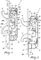
Figure 1 is a partially cross-sectional perspective view of a security shootbolt for a multipoint lock according to the invention, with latches extracted; -
Figure 2 is a side view of the shootbolt ofFigure 1 ; -
Figure 3 is a partially cross-sectional perspective view of the shootbolt ofFigure 1 , with latches retracted; -
Figure 4 is a side view of the shootbolt ofFigure 3 ; -
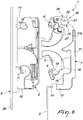
Figure 5 is an exploded perspective view of the shootbolt ofFigure 1 ; -
Figure 6 is an exploded side view of the shootbolt ofFigure 5 . - With reference to the figures, the
reference numeral 1 generally designates a security shootbolt for a multipoint lock. - The
security shootbolt 1 comprises a box-likeexternal body 2 and two hook-shaped latches - The
latches respective pin like body 2. - The
latches actuation slide 7 which is in turn integral with anactuation rod 8 of a main lock. - The
pin 5 for pivoting afirst latch 3 is arranged proximate to theexternal face 9 of the box-like body 2 and of theregion 10 of entry of theactuation rod 8 of the main lock. - The
pin 6 of thesecond latch 4 is arranged proximate to theexternal face 9 of the box-like body 2 and to theportion 11 opposite theregion 10 of entry of therod 8. - The
slide 7 comprises afirst end 12 for coupling to the actuation rod 8: in particular such end can comprise aseat 13 for the accommodation of thehead 14 of therod 8; thehead 14 can be locked in theseat 13 by way of further components or by way of mechanically closing theend 12 with consequent pressing of the walls of theseat 13 onto thehead 14 of therod 8. - The
slide 7 further comprises anabutment tooth 15 for ashoulder 16 of thefirst latch 3. - Downstream of the
tooth 15, the slide comprises astraight section 17 andelements 18 for coupling to thesecond latch 4. - The
first latch 3 comprises arecess 19, proximate to theshoulder 16, for the entry, or more correctly the temporary accommodation, of thetooth 15 of theslide 7, in the event thefirst latch 3 is forced to retract in order to break and enter. - The temporary accommodation of the
tooth 15 in therecess 19 results in the temporary decoupling of thefirst latch 3 from the slide 7 (because thelatch 3 is rotatable about itspin 5, retracting inside the box-like body 2, without theslide 7 undergoing any translation) and this ensures that thesecond latch 4 is kept in the extraction configuration, thus ensuring the locking in the closed position of the door leaf in which theshootbolt 1 is installed. - The
elements 18 for coupling to thesecond latch 4 of theslide 7 comprise ameshing rack 17a for agearwheel 20 which is pivoted (according to an axis 21) on the box-like body 2 and which meshes with atoothing 22 of thesecond latch 4. - The
gearwheel 20 comprisestoothed sectors - A
first toothed sector 23 is contoured to mesh with therack 17a and asecond toothed sector 24 is contoured to mesh with thetoothing 22 of thesecond latch 4. - The
slide 7 comprises anabutment protrusion 26 for anappendage 27 of thesecond latch 4. - The
protrusion 26 is arranged on thestraight section 17 of theslide 7, upstream of theelements 18 for coupling to thesecond latch 4. - According to an embodiment of undoubted applicative interest, the
recess 19 is interposed between theshoulder 16 and thepin 5 of thefirst latch 3. - In such case, the
recess 19 will be constituted by a substantially circular concavity: the purpose of the radiused progression of the concavity is to facilitate the sliding of thetooth 15, without its becoming jammed. - The box-
like body 2 comprises aplate 28 on its external face 9: theplate 28 can be coupled to the edge of the door leaf of installation of theshootbolt 1. - The
plate 28 comprises at least oneslot latches - With particular reference to the embodiment shown in the accompanying figures, the
slot 28a can accommodate thelatch 3 and theslot 28b can accommodate thelatch 4, in the configuration in which thelatches like body 2. - Therefore, if an attempt at forcing is made, in which one of the two
latches like body 2, there will be no corresponding retraction of theother latch shootbolt 1. - In fact, in the accompanying
Figures 1 and 2 it can be clearly seen that thelatches slide 7 in the configuration of full extraction (protrusion): theabutment tooth 15 of theslide 7 will allow the resting of theshoulder 16, thus preventing its retraction; theabutment protrusion 26 of theslide 7 will allow the resting of theappendage 27, thus preventing its retraction. - Even if there is a slight retraction of the
rod 8, therecess 19 will be facing and proximate to theabutment 15, and therefore the retraction of thefirst latch 3 can occur without it entraining thesecond latch 4 as well, seeing that such retraction movement will not in fact in any way be transmitted to theslide 7. - The present invention also extends its protection to a multipoint lock of the type comprising a main lock to which is coupled at least one
security shootbolt 1 of the type described previously. - The
shootbolt 1 will be mechanically coupled to the main lock by way of arespective actuation rod 8 of the main lock (which will need to be of the type suitable foroperating actuation rods 8 for shootbolts). - More specifically, the multipoint lock according to the invention can comprise two separate shootbolts 1: a
first shootbolt 1 will be arranged above the main lock and asecond shootbolt 1 will be arranged below the main lock. - The lock will comprise an
upper actuation rod 8, which is functionally associated with thefirst shootbolt 1, and alower actuation rod 8, which is functionally associated with thesecond shootbolt 1. - Advantageously, the present invention solves the above-mentioned problems, by providing a
security shootbolt 1 for multipoint locks that is protected against attempts at forcing carried out on therespective latches 3, 4: in fact the forced retraction of one of the twolatches other latch - Any attempt at forcing is therefore heavily obstructed, since it can be effective only if the retraction is simultaneously forced of both
latches - Conveniently the
security shootbolt 1 according to the invention is provided with hook-shaped latches - Positively the present invention envisages the production of a
security shootbolt 1 for multipoint locks that is easily and practically implemented and which is low cost. - The invention, thus conceived, is susceptible of numerous modifications and variations, all of which are within the scope of the appended claims.
- In practice, the materials employed, as well as the dimensions, may be any according to requirements and to the state of the art.
- Where the technical features mentioned in any claim are followed by reference numerals and/or signs, those reference numerals and/or signs have been included for the sole purpose of increasing the intelligibility of the claims and accordingly, such reference numerals and/or signs do not have any limiting effect on the interpretation of each element identified by way of example by such reference numerals and/or signs.
Claims (9)
- A security shootbolt for a multipoint lock, comprising an external box-like body (2) and two hook-shaped latches (3, 4) that can rotate about a respective pin (5, 6) for fixing to the box-like body (2), and an actuation slide (7), said latches (3, 4) being functionally associated with said actuation slide (7) which in turn is integral with an actuation rod (8) of a main lock, the pivoting pin (5) of a first latch (3) being arranged proximate to the external face (9) of said box-like body (2) and to the region (10) of entry of the actuation rod (8) of the main lock, the pin (6) of the second latch (4) being arranged proximate to the external face (9) of said box-like body (2) and to the portion (11) opposite the region (10) of entry of the rod (8), said slide (7) comprising a first end (12) for coupling to said actuation rod (8), and a straight section (17) and elements (18) for coupling to said second latch (4), characterized in that said slide (7) comprises an abutment tooth (15) for a shoulder (16) of said first latch (3) so that in the configuration of full extraction, said abutment tooth (15) of said slide (7) will allow the resting of said shoulder (16), thus preventing its extraction, said first latch (3) comprising a recess (19) proximate to said shoulder (16) for the entry of said tooth (15) of said slide (7) in the event the first latch (3) is forced to retract in order to break and enter, with consequent temporary decoupling of said first latch (3) from said slide (7) and maintenance of the second latch (4) in the extraction configuration, and vice versa.
- The security shootbolt according to claim 1, characterized in that said elements (18) for coupling to said second latch (4) of said slide (7) comprise a meshing rack (17a) for a gearwheel (20) which is pivoted on said box-like body (2) and which meshes with a toothing (22) of the said second latch (4).
- The security shootbolt according to claim 2, characterized in that said gearwheel (20) comprises toothed sectors (23, 24) interspersed by sectors (25) with a substantially circular smooth profile, a first toothed sector (23) being contoured to mesh with said rack (17a) and a second toothed sector (24) being contoured to mesh with said toothing (22) of said second latch (4).
- The security shootbolt according to claim 1, characterized in that said slide (7) comprises an abutment protrusion (26) for an appendage (27) of said second latch (4), said protrusion (26) being arranged on said straight section (17), upstream of the said elements (18) for coupling to said second latch (4).
- The security shootbolt according to claim 1, characterized in that said recess (19) is interposed between said shoulder (16) and said pin (5) of the said first latch (3), said recess (19) being constituted by a substantially circular concavity.
- The security shootbolt according to claim 1, characterized in that said box-like body (2) comprises a plate (28) on its external face, it being possible to couple said plate (28) to the edge of the door leaf of installation of said shootbolt (1).
- The security shootbolt according to claim 6, characterized in that said plate (28) comprises at least one slot (28a, 28b) for the passage of said latches (3, 4).
- A multipoint lock of the type comprising a main lock, characterized in that it comprises at least one security shootbolt (1) according to at least one of the preceding claims, said shootbolt (1) being mechanically coupled to said main lock by way of a respective actuation rod (8) of the said main lock.
- The multipoint lock according to claim 8, characterized in that said shootbolts (1) are two in number, a first shootbolt (1) being arranged above said main lock and a second shootbolt being arranged below said main lock, said lock comprising an upper actuation rod (8), which is functionally associated with said first shootbolt (1), and a lower actuation rod (8), which is functionally associated with said second shootbolt (1).
Applications Claiming Priority (1)
| Application Number | Priority Date | Filing Date | Title |
|---|---|---|---|
| PCT/IT2017/000072 WO2018189754A1 (en) | 2017-04-10 | 2017-04-10 | Security shootbolt for multipoint lock |
Publications (2)
| Publication Number | Publication Date |
|---|---|
| EP3610107A1 EP3610107A1 (en) | 2020-02-19 |
| EP3610107B1 true EP3610107B1 (en) | 2021-03-17 |
Family
ID=59253839
Family Applications (1)
| Application Number | Title | Priority Date | Filing Date |
|---|---|---|---|
| EP17734146.8A Active EP3610107B1 (en) | 2017-04-10 | 2017-04-10 | Security shootbolt for multipoint lock |
Country Status (3)
| Country | Link |
|---|---|
| EP (1) | EP3610107B1 (en) |
| ES (1) | ES2876398T3 (en) |
| WO (1) | WO2018189754A1 (en) |
Families Citing this family (3)
| Publication number | Priority date | Publication date | Assignee | Title |
|---|---|---|---|---|
| GB2572776B (en) * | 2018-04-10 | 2022-04-20 | Security Hardware Ltd | A lock |
| CN110159100B (en) * | 2019-05-31 | 2021-06-29 | 台州闻涛科技有限公司 | Multi-locking point intelligent concealed article interlocking |
| CN111155856B (en) * | 2020-03-13 | 2021-08-03 | 台州傲京厨卫有限公司 | Door stopper |
Family Cites Families (4)
| Publication number | Priority date | Publication date | Assignee | Title |
|---|---|---|---|---|
| DE4304214C2 (en) * | 1993-02-12 | 2002-03-14 | Fliether Karl Gmbh & Co | Lock to be used in particular on apartment lock doors, in particular lock which can be actuated by a connecting rod |
| DE19813166A1 (en) * | 1998-03-25 | 1999-10-14 | Winkhaus Fa August | Door lock arrangement, preferably espagnolette lock arrangement |
| FR2789715B1 (en) * | 1999-02-17 | 2001-03-30 | Ferco Int Usine Ferrures | LOCK CREMONE COMPRISING A LOCK WITH A SECURE LOCKING HOOK |
| CA2490922A1 (en) * | 2004-12-23 | 2006-06-23 | Azuma Design Pty Limited | Sliding door lock |
-
2017
- 2017-04-10 ES ES17734146T patent/ES2876398T3/en active Active
- 2017-04-10 EP EP17734146.8A patent/EP3610107B1/en active Active
- 2017-04-10 WO PCT/IT2017/000072 patent/WO2018189754A1/en unknown
Non-Patent Citations (1)
| Title |
|---|
| None * |
Also Published As
| Publication number | Publication date |
|---|---|
| ES2876398T3 (en) | 2021-11-12 |
| WO2018189754A1 (en) | 2018-10-18 |
| EP3610107A1 (en) | 2020-02-19 |
Similar Documents
| Publication | Publication Date | Title |
|---|---|---|
| EP3610107B1 (en) | Security shootbolt for multipoint lock | |
| US20170030112A1 (en) | Multipoint locking door hardware | |
| WO2004083575A1 (en) | Enhanced extendable multipoint lock | |
| WO2013019281A1 (en) | Interchangeable mortise lock cylinder | |
| KR101986613B1 (en) | Door locks for sliding doors | |
| DK2941520T3 (en) | KEY WITH MOVING ELEMENT LOCATED IN KEY SHEET | |
| RU132116U1 (en) | SOUVALD LOCK AND KEY | |
| EP3749821B1 (en) | Peripheral assembly for multipoint locks | |
| CN108952329A (en) | A kind of anti-card door lock | |
| RU147112U1 (en) | SOUVALD LOCK | |
| RU2602051C1 (en) | Safety lock for fire and front doors | |
| EP2310599B1 (en) | Universal security lock | |
| RU2560917C2 (en) | Safety lock with locking plates, in particular, for armoured doors | |
| EP2532811A1 (en) | Double-bit safety lock | |
| EP2171187A1 (en) | Selector for locks for reinforced doors and the like | |
| TW201544669A (en) | A safety lock with an additional security improvement | |
| WO2009008015A1 (en) | Lock for reinforced doors and the like | |
| EP3749819B1 (en) | Lock for double-leaf doors | |
| US11261620B2 (en) | Blocking lock with matrix coding system | |
| EP3577291B1 (en) | Soundproof lock | |
| RU2493342C2 (en) | Security lock | |
| EP2388419B1 (en) | Mortise lock | |
| AU2012238281B2 (en) | Sliding Door Locks | |
| KR200484883Y1 (en) | Panic assembly for doorlock mortise having numerous deadbolt | |
| GB2319289A (en) | Fastening assembly comprising bolt and keeper |
Legal Events
| Date | Code | Title | Description |
|---|---|---|---|
| STAA | Information on the status of an ep patent application or granted ep patent |
Free format text: STATUS: UNKNOWN |
|
| STAA | Information on the status of an ep patent application or granted ep patent |
Free format text: STATUS: THE INTERNATIONAL PUBLICATION HAS BEEN MADE |
|
| PUAI | Public reference made under article 153(3) epc to a published international application that has entered the european phase |
Free format text: ORIGINAL CODE: 0009012 |
|
| STAA | Information on the status of an ep patent application or granted ep patent |
Free format text: STATUS: REQUEST FOR EXAMINATION WAS MADE |
|
| 17P | Request for examination filed |
Effective date: 20191011 |
|
| AK | Designated contracting states |
Kind code of ref document: A1 Designated state(s): AL AT BE BG CH CY CZ DE DK EE ES FI FR GB GR HR HU IE IS IT LI LT LU LV MC MK MT NL NO PL PT RO RS SE SI SK SM TR |
|
| GRAP | Despatch of communication of intention to grant a patent |
Free format text: ORIGINAL CODE: EPIDOSNIGR1 |
|
| STAA | Information on the status of an ep patent application or granted ep patent |
Free format text: STATUS: GRANT OF PATENT IS INTENDED |
|
| RIC1 | Information provided on ipc code assigned before grant |
Ipc: E05B 63/14 20060101ALN20200911BHEP Ipc: E05B 15/10 20060101ALI20200911BHEP Ipc: E05C 9/18 20060101AFI20200911BHEP Ipc: E05B 17/20 20060101ALI20200911BHEP |
|
| INTG | Intention to grant announced |
Effective date: 20200928 |
|
| GRAS | Grant fee paid |
Free format text: ORIGINAL CODE: EPIDOSNIGR3 |
|
| GRAA | (expected) grant |
Free format text: ORIGINAL CODE: 0009210 |
|
| STAA | Information on the status of an ep patent application or granted ep patent |
Free format text: STATUS: THE PATENT HAS BEEN GRANTED |
|
| AK | Designated contracting states |
Kind code of ref document: B1 Designated state(s): AL AT BE BG CH CY CZ DE DK EE ES FI FR GB GR HR HU IE IS IT LI LT LU LV MC MK MT NL NO PL PT RO RS SE SI SK SM TR |
|
| REG | Reference to a national code |
Ref country code: GB Ref legal event code: FG4D |
|
| REG | Reference to a national code |
Ref country code: CH Ref legal event code: EP |
|
| REG | Reference to a national code |
Ref country code: DE Ref legal event code: R096 Ref document number: 602017034775 Country of ref document: DE |
|
| REG | Reference to a national code |
Ref country code: IE Ref legal event code: FG4D |
|
| REG | Reference to a national code |
Ref country code: AT Ref legal event code: REF Ref document number: 1372386 Country of ref document: AT Kind code of ref document: T Effective date: 20210415 |
|
| REG | Reference to a national code |
Ref country code: NL Ref legal event code: FP |
|
| REG | Reference to a national code |
Ref country code: LT Ref legal event code: MG9D |
|
| PG25 | Lapsed in a contracting state [announced via postgrant information from national office to epo] |
Ref country code: BG Free format text: LAPSE BECAUSE OF FAILURE TO SUBMIT A TRANSLATION OF THE DESCRIPTION OR TO PAY THE FEE WITHIN THE PRESCRIBED TIME-LIMIT Effective date: 20210617 Ref country code: NO Free format text: LAPSE BECAUSE OF FAILURE TO SUBMIT A TRANSLATION OF THE DESCRIPTION OR TO PAY THE FEE WITHIN THE PRESCRIBED TIME-LIMIT Effective date: 20210617 Ref country code: GR Free format text: LAPSE BECAUSE OF FAILURE TO SUBMIT A TRANSLATION OF THE DESCRIPTION OR TO PAY THE FEE WITHIN THE PRESCRIBED TIME-LIMIT Effective date: 20210618 Ref country code: FI Free format text: LAPSE BECAUSE OF FAILURE TO SUBMIT A TRANSLATION OF THE DESCRIPTION OR TO PAY THE FEE WITHIN THE PRESCRIBED TIME-LIMIT Effective date: 20210317 Ref country code: HR Free format text: LAPSE BECAUSE OF FAILURE TO SUBMIT A TRANSLATION OF THE DESCRIPTION OR TO PAY THE FEE WITHIN THE PRESCRIBED TIME-LIMIT Effective date: 20210317 |
|
| REG | Reference to a national code |
Ref country code: AT Ref legal event code: MK05 Ref document number: 1372386 Country of ref document: AT Kind code of ref document: T Effective date: 20210317 |
|
| PG25 | Lapsed in a contracting state [announced via postgrant information from national office to epo] |
Ref country code: RS Free format text: LAPSE BECAUSE OF FAILURE TO SUBMIT A TRANSLATION OF THE DESCRIPTION OR TO PAY THE FEE WITHIN THE PRESCRIBED TIME-LIMIT Effective date: 20210317 Ref country code: LV Free format text: LAPSE BECAUSE OF FAILURE TO SUBMIT A TRANSLATION OF THE DESCRIPTION OR TO PAY THE FEE WITHIN THE PRESCRIBED TIME-LIMIT Effective date: 20210317 Ref country code: SE Free format text: LAPSE BECAUSE OF FAILURE TO SUBMIT A TRANSLATION OF THE DESCRIPTION OR TO PAY THE FEE WITHIN THE PRESCRIBED TIME-LIMIT Effective date: 20210317 |
|
| PG25 | Lapsed in a contracting state [announced via postgrant information from national office to epo] |
Ref country code: LT Free format text: LAPSE BECAUSE OF FAILURE TO SUBMIT A TRANSLATION OF THE DESCRIPTION OR TO PAY THE FEE WITHIN THE PRESCRIBED TIME-LIMIT Effective date: 20210317 Ref country code: EE Free format text: LAPSE BECAUSE OF FAILURE TO SUBMIT A TRANSLATION OF THE DESCRIPTION OR TO PAY THE FEE WITHIN THE PRESCRIBED TIME-LIMIT Effective date: 20210317 Ref country code: CZ Free format text: LAPSE BECAUSE OF FAILURE TO SUBMIT A TRANSLATION OF THE DESCRIPTION OR TO PAY THE FEE WITHIN THE PRESCRIBED TIME-LIMIT Effective date: 20210317 Ref country code: AT Free format text: LAPSE BECAUSE OF FAILURE TO SUBMIT A TRANSLATION OF THE DESCRIPTION OR TO PAY THE FEE WITHIN THE PRESCRIBED TIME-LIMIT Effective date: 20210317 Ref country code: SM Free format text: LAPSE BECAUSE OF FAILURE TO SUBMIT A TRANSLATION OF THE DESCRIPTION OR TO PAY THE FEE WITHIN THE PRESCRIBED TIME-LIMIT Effective date: 20210317 |
|
| REG | Reference to a national code |
Ref country code: DE Ref legal event code: R119 Ref document number: 602017034775 Country of ref document: DE |
|
| REG | Reference to a national code |
Ref country code: ES Ref legal event code: FG2A Ref document number: 2876398 Country of ref document: ES Kind code of ref document: T3 Effective date: 20211112 |
|
| PG25 | Lapsed in a contracting state [announced via postgrant information from national office to epo] |
Ref country code: IS Free format text: LAPSE BECAUSE OF FAILURE TO SUBMIT A TRANSLATION OF THE DESCRIPTION OR TO PAY THE FEE WITHIN THE PRESCRIBED TIME-LIMIT Effective date: 20210717 Ref country code: RO Free format text: LAPSE BECAUSE OF FAILURE TO SUBMIT A TRANSLATION OF THE DESCRIPTION OR TO PAY THE FEE WITHIN THE PRESCRIBED TIME-LIMIT Effective date: 20210317 Ref country code: SK Free format text: LAPSE BECAUSE OF FAILURE TO SUBMIT A TRANSLATION OF THE DESCRIPTION OR TO PAY THE FEE WITHIN THE PRESCRIBED TIME-LIMIT Effective date: 20210317 Ref country code: PT Free format text: LAPSE BECAUSE OF FAILURE TO SUBMIT A TRANSLATION OF THE DESCRIPTION OR TO PAY THE FEE WITHIN THE PRESCRIBED TIME-LIMIT Effective date: 20210719 Ref country code: PL Free format text: LAPSE BECAUSE OF FAILURE TO SUBMIT A TRANSLATION OF THE DESCRIPTION OR TO PAY THE FEE WITHIN THE PRESCRIBED TIME-LIMIT Effective date: 20210317 |
|
| PG25 | Lapsed in a contracting state [announced via postgrant information from national office to epo] |
Ref country code: LU Free format text: LAPSE BECAUSE OF NON-PAYMENT OF DUE FEES Effective date: 20210410 |
|
| REG | Reference to a national code |
Ref country code: BE Ref legal event code: MM Effective date: 20210430 |
|
| PLBE | No opposition filed within time limit |
Free format text: ORIGINAL CODE: 0009261 |
|
| STAA | Information on the status of an ep patent application or granted ep patent |
Free format text: STATUS: NO OPPOSITION FILED WITHIN TIME LIMIT |
|
| PG25 | Lapsed in a contracting state [announced via postgrant information from national office to epo] |
Ref country code: MC Free format text: LAPSE BECAUSE OF FAILURE TO SUBMIT A TRANSLATION OF THE DESCRIPTION OR TO PAY THE FEE WITHIN THE PRESCRIBED TIME-LIMIT Effective date: 20210317 Ref country code: DE Free format text: LAPSE BECAUSE OF NON-PAYMENT OF DUE FEES Effective date: 20211103 Ref country code: DK Free format text: LAPSE BECAUSE OF FAILURE TO SUBMIT A TRANSLATION OF THE DESCRIPTION OR TO PAY THE FEE WITHIN THE PRESCRIBED TIME-LIMIT Effective date: 20210317 Ref country code: CH Free format text: LAPSE BECAUSE OF NON-PAYMENT OF DUE FEES Effective date: 20210430 Ref country code: AL Free format text: LAPSE BECAUSE OF FAILURE TO SUBMIT A TRANSLATION OF THE DESCRIPTION OR TO PAY THE FEE WITHIN THE PRESCRIBED TIME-LIMIT Effective date: 20210317 Ref country code: LI Free format text: LAPSE BECAUSE OF NON-PAYMENT OF DUE FEES Effective date: 20210430 |
|
| 26N | No opposition filed |
Effective date: 20211220 |
|
| GBPC | Gb: european patent ceased through non-payment of renewal fee |
Effective date: 20210617 |
|
| PG25 | Lapsed in a contracting state [announced via postgrant information from national office to epo] |
Ref country code: SI Free format text: LAPSE BECAUSE OF FAILURE TO SUBMIT A TRANSLATION OF THE DESCRIPTION OR TO PAY THE FEE WITHIN THE PRESCRIBED TIME-LIMIT Effective date: 20210317 |
|
| PG25 | Lapsed in a contracting state [announced via postgrant information from national office to epo] |
Ref country code: IE Free format text: LAPSE BECAUSE OF NON-PAYMENT OF DUE FEES Effective date: 20210410 Ref country code: GB Free format text: LAPSE BECAUSE OF NON-PAYMENT OF DUE FEES Effective date: 20210617 |
|
| PG25 | Lapsed in a contracting state [announced via postgrant information from national office to epo] |
Ref country code: IS Free format text: LAPSE BECAUSE OF FAILURE TO SUBMIT A TRANSLATION OF THE DESCRIPTION OR TO PAY THE FEE WITHIN THE PRESCRIBED TIME-LIMIT Effective date: 20210717 Ref country code: FR Free format text: LAPSE BECAUSE OF NON-PAYMENT OF DUE FEES Effective date: 20210517 |
|
| PG25 | Lapsed in a contracting state [announced via postgrant information from national office to epo] |
Ref country code: BE Free format text: LAPSE BECAUSE OF NON-PAYMENT OF DUE FEES Effective date: 20210430 |
|
| PG25 | Lapsed in a contracting state [announced via postgrant information from national office to epo] |
Ref country code: CY Free format text: LAPSE BECAUSE OF FAILURE TO SUBMIT A TRANSLATION OF THE DESCRIPTION OR TO PAY THE FEE WITHIN THE PRESCRIBED TIME-LIMIT Effective date: 20210317 |
|
| P01 | Opt-out of the competence of the unified patent court (upc) registered |
Effective date: 20230526 |
|
| PG25 | Lapsed in a contracting state [announced via postgrant information from national office to epo] |
Ref country code: HU Free format text: LAPSE BECAUSE OF FAILURE TO SUBMIT A TRANSLATION OF THE DESCRIPTION OR TO PAY THE FEE WITHIN THE PRESCRIBED TIME-LIMIT; INVALID AB INITIO Effective date: 20170410 |
|
| PGFP | Annual fee paid to national office [announced via postgrant information from national office to epo] |
Ref country code: IT Payment date: 20230406 Year of fee payment: 7 Ref country code: ES Payment date: 20230505 Year of fee payment: 7 |
|
| PG25 | Lapsed in a contracting state [announced via postgrant information from national office to epo] |
Ref country code: MK Free format text: LAPSE BECAUSE OF FAILURE TO SUBMIT A TRANSLATION OF THE DESCRIPTION OR TO PAY THE FEE WITHIN THE PRESCRIBED TIME-LIMIT Effective date: 20210317 |
|
| PGFP | Annual fee paid to national office [announced via postgrant information from national office to epo] |
Ref country code: NL Payment date: 20240419 Year of fee payment: 8 |