EP3609739B1 - Interchanging method and arrangement for interchanging load units - Google Patents
Interchanging method and arrangement for interchanging load units Download PDFInfo
- Publication number
- EP3609739B1 EP3609739B1 EP17785516.0A EP17785516A EP3609739B1 EP 3609739 B1 EP3609739 B1 EP 3609739B1 EP 17785516 A EP17785516 A EP 17785516A EP 3609739 B1 EP3609739 B1 EP 3609739B1
- Authority
- EP
- European Patent Office
- Prior art keywords
- load unit
- load
- interchanging
- vehicle
- unit
- Prior art date
- Legal status (The legal status is an assumption and is not a legal conclusion. Google has not performed a legal analysis and makes no representation as to the accuracy of the status listed.)
- Active
Links
Images



Classifications
-
- B—PERFORMING OPERATIONS; TRANSPORTING
- B60—VEHICLES IN GENERAL
- B60P—VEHICLES ADAPTED FOR LOAD TRANSPORTATION OR TO TRANSPORT, TO CARRY, OR TO COMPRISE SPECIAL LOADS OR OBJECTS
- B60P1/00—Vehicles predominantly for transporting loads and modified to facilitate loading, consolidating the load, or unloading
- B60P1/48—Vehicles predominantly for transporting loads and modified to facilitate loading, consolidating the load, or unloading using pivoted arms raisable above load-transporting element
- B60P1/483—Vehicles predominantly for transporting loads and modified to facilitate loading, consolidating the load, or unloading using pivoted arms raisable above load-transporting element using pivoted arms shifting the load-transporting element in a fore or aft direction
-
- B—PERFORMING OPERATIONS; TRANSPORTING
- B60—VEHICLES IN GENERAL
- B60P—VEHICLES ADAPTED FOR LOAD TRANSPORTATION OR TO TRANSPORT, TO CARRY, OR TO COMPRISE SPECIAL LOADS OR OBJECTS
- B60P1/00—Vehicles predominantly for transporting loads and modified to facilitate loading, consolidating the load, or unloading
- B60P1/64—Vehicles predominantly for transporting loads and modified to facilitate loading, consolidating the load, or unloading the load supporting or containing element being readily removable
-
- B—PERFORMING OPERATIONS; TRANSPORTING
- B60—VEHICLES IN GENERAL
- B60P—VEHICLES ADAPTED FOR LOAD TRANSPORTATION OR TO TRANSPORT, TO CARRY, OR TO COMPRISE SPECIAL LOADS OR OBJECTS
- B60P1/00—Vehicles predominantly for transporting loads and modified to facilitate loading, consolidating the load, or unloading
- B60P1/64—Vehicles predominantly for transporting loads and modified to facilitate loading, consolidating the load, or unloading the load supporting or containing element being readily removable
- B60P1/6409—Vehicles predominantly for transporting loads and modified to facilitate loading, consolidating the load, or unloading the load supporting or containing element being readily removable details, accessories, auxiliary devices
-
- B—PERFORMING OPERATIONS; TRANSPORTING
- B60—VEHICLES IN GENERAL
- B60P—VEHICLES ADAPTED FOR LOAD TRANSPORTATION OR TO TRANSPORT, TO CARRY, OR TO COMPRISE SPECIAL LOADS OR OBJECTS
- B60P1/00—Vehicles predominantly for transporting loads and modified to facilitate loading, consolidating the load, or unloading
- B60P1/64—Vehicles predominantly for transporting loads and modified to facilitate loading, consolidating the load, or unloading the load supporting or containing element being readily removable
- B60P1/6418—Vehicles predominantly for transporting loads and modified to facilitate loading, consolidating the load, or unloading the load supporting or containing element being readily removable the load-transporting element being a container or similar
- B60P1/6427—Vehicles predominantly for transporting loads and modified to facilitate loading, consolidating the load, or unloading the load supporting or containing element being readily removable the load-transporting element being a container or similar the load-transporting element being shifted horizontally in a fore and aft direction, combined or not with a vertical displacement
-
- B—PERFORMING OPERATIONS; TRANSPORTING
- B60—VEHICLES IN GENERAL
- B60P—VEHICLES ADAPTED FOR LOAD TRANSPORTATION OR TO TRANSPORT, TO CARRY, OR TO COMPRISE SPECIAL LOADS OR OBJECTS
- B60P1/00—Vehicles predominantly for transporting loads and modified to facilitate loading, consolidating the load, or unloading
- B60P1/64—Vehicles predominantly for transporting loads and modified to facilitate loading, consolidating the load, or unloading the load supporting or containing element being readily removable
- B60P1/6418—Vehicles predominantly for transporting loads and modified to facilitate loading, consolidating the load, or unloading the load supporting or containing element being readily removable the load-transporting element being a container or similar
- B60P1/6463—Vehicles predominantly for transporting loads and modified to facilitate loading, consolidating the load, or unloading the load supporting or containing element being readily removable the load-transporting element being a container or similar fitted with articulated beams for longitudinal displacement of the container
-
- B—PERFORMING OPERATIONS; TRANSPORTING
- B60—VEHICLES IN GENERAL
- B60P—VEHICLES ADAPTED FOR LOAD TRANSPORTATION OR TO TRANSPORT, TO CARRY, OR TO COMPRISE SPECIAL LOADS OR OBJECTS
- B60P1/00—Vehicles predominantly for transporting loads and modified to facilitate loading, consolidating the load, or unloading
- B60P1/64—Vehicles predominantly for transporting loads and modified to facilitate loading, consolidating the load, or unloading the load supporting or containing element being readily removable
- B60P1/6418—Vehicles predominantly for transporting loads and modified to facilitate loading, consolidating the load, or unloading the load supporting or containing element being readily removable the load-transporting element being a container or similar
- B60P1/6481—Specially adapted for carrying different numbers of container or containers of different sizes
-
- B—PERFORMING OPERATIONS; TRANSPORTING
- B60—VEHICLES IN GENERAL
- B60P—VEHICLES ADAPTED FOR LOAD TRANSPORTATION OR TO TRANSPORT, TO CARRY, OR TO COMPRISE SPECIAL LOADS OR OBJECTS
- B60P1/00—Vehicles predominantly for transporting loads and modified to facilitate loading, consolidating the load, or unloading
- B60P1/64—Vehicles predominantly for transporting loads and modified to facilitate loading, consolidating the load, or unloading the load supporting or containing element being readily removable
- B60P1/6418—Vehicles predominantly for transporting loads and modified to facilitate loading, consolidating the load, or unloading the load supporting or containing element being readily removable the load-transporting element being a container or similar
- B60P1/649—Guiding means for the load-transporting element
-
- B—PERFORMING OPERATIONS; TRANSPORTING
- B65—CONVEYING; PACKING; STORING; HANDLING THIN OR FILAMENTARY MATERIAL
- B65F—GATHERING OR REMOVAL OF DOMESTIC OR LIKE REFUSE
- B65F3/00—Vehicles particularly adapted for collecting refuse
- B65F3/001—Vehicles particularly adapted for collecting refuse for segregated refuse collecting, e.g. vehicles with several compartments
-
- B—PERFORMING OPERATIONS; TRANSPORTING
- B65—CONVEYING; PACKING; STORING; HANDLING THIN OR FILAMENTARY MATERIAL
- B65F—GATHERING OR REMOVAL OF DOMESTIC OR LIKE REFUSE
- B65F3/00—Vehicles particularly adapted for collecting refuse
- B65F2003/006—Constructional features relating to the tank of the refuse vehicle
- B65F2003/008—Constructional features relating to the tank of the refuse vehicle interchangeable
-
- B—PERFORMING OPERATIONS; TRANSPORTING
- B65—CONVEYING; PACKING; STORING; HANDLING THIN OR FILAMENTARY MATERIAL
- B65G—TRANSPORT OR STORAGE DEVICES, e.g. CONVEYORS FOR LOADING OR TIPPING, SHOP CONVEYOR SYSTEMS OR PNEUMATIC TUBE CONVEYORS
- B65G57/00—Stacking of articles
- B65G57/02—Stacking of articles by adding to the top of the stack
- B65G57/03—Stacking of articles by adding to the top of the stack from above
-
- B—PERFORMING OPERATIONS; TRANSPORTING
- B65—CONVEYING; PACKING; STORING; HANDLING THIN OR FILAMENTARY MATERIAL
- B65G—TRANSPORT OR STORAGE DEVICES, e.g. CONVEYORS FOR LOADING OR TIPPING, SHOP CONVEYOR SYSTEMS OR PNEUMATIC TUBE CONVEYORS
- B65G67/00—Loading or unloading vehicles
- B65G67/02—Loading or unloading land vehicles
Definitions
- a prior art system of DE 10325373 A1 for interchanging load units or skips.
- the system has a displacement unit combining a longitudinal displacer and a vertical displacer for interchanging skips on a vehicle.
- the vehicle approaches the loaded skip, while the empty one remains on the loading area of the vehicle.
- the lifting arms of the conventional skip body lift the full container from the ground.
- the lifting arm telescopes are extended, after which the loaded container can be picked up with the telescope extended.
- the exchange container (empty) is transported backwards to behind the rear of the vehicle.
- the unit is lowered to the ground. After this the loaded container can be placed on the loading area for removal.
- An object of the invention is to alleviate and eliminate the problems relating to the known prior art.
- Especially the object of the invention is to provide an arrangement and method for interchanging containers or other load units so that the interchanging process of the containers can be done on the site without a need for leaving the empty container somewhere other place at first, take the full container and transfer it somewhere else, take the empty container again and transfer it to the destination site and after this to take the original full container again on the vehicle.
- Especially the object of the invention is to provide an arrangement and method so that the containers can be replaced or interchanged without any need for moving the vehicle and so that the new container brought to the site is placed essentially on the same location than the container to be taken away.
- an interchanging arrangement for interchanging at least first and second load units carried by a vehicle.
- the interchanging the load unit means e.g. unloading a first load unit from the vehicle on the ground and loading a second load unit to the same vehicle.
- the load unit is e.g. an interchangeable platform or container or the like having first and second ends.
- the arrangement is advantageously mountable on the vehicle or to the load unit, in particularly to the end portion of the load unit.
- the interchanging arrangement or the vehicle comprises a moving device, such as e.g. a traditional hook system or any other possible implementation, such as a chain, strap, belt or cable arranged for moving and unloading the first load unit from the vehicle in a first direction, typically backwards.
- a moving device such as e.g. a traditional hook system or any other possible implementation, such as a chain, strap, belt or cable arranged for moving and unloading the first load unit from the vehicle in a first direction, typically backwards.
- the first load unit is moved onto the top of the second load unit locating next to the vehicle, such as on the ground and on the backside or rear extension of the vehicle, for example.
- the moving device releases the first load unit and grips the second load unit below the first load unit.
- the first load unit When gripped it moves and loads the second load unit onto the vehicle so that the first load unit is still (at least partially) on the top of the second load unit at least at the beginning of the moving of the second load unit and so that the first load unit slides on the top and along the second load unit essentially in said first direction in relation to the second load unit during loading the second load unit onto the vehicle.
- the first load unit slides on the top and along the second load unit until the first end of the first load unit meets and/or passes the second end of the second load unit. Also the second end of the first load unit typically meets the ground when the first load unit slides along the second load unit.
- the interchanging arrangement comprises also a landing device arranged between the first end of the first load unit and the second end of the second load unit moving or lowering the first end of the first load unit to the ground in a secured and advantageously also in a controllable manner.
- a first portion of the landing device is supported to the first end of the first load unit and a second portion of the landing device is supported to the second end of the second load unit.
- the landing device can be implemented e.g. by a cable or hook with a braking cylinder, for example.
- the landing device is configured to move the first end of said first load unit into the lower level than the second end of the second load unit, advantageously to the ground.
- Lowering the first end of the first load unit is configured to happen when the moving device moves and loads the second load unit onto the vehicle, and after the first end of the first load unit has met and advantageously also passed or is passing the second end of the second load unit.
- the arrangement or the landing device comprises also a braking member to slow down the landing of the first end of the first load unit so that the first end of the first load unit does not hit the ground due to the gravity and cause any damage or dangerous situation.
- the braking member can be implemented e.g. by a brake cylinder, such as a pneumatic or hydraulic cylinder or a spring or a mechanical construction, such as a friction brake.
- an electric or hydraulic motor can be used for braking or resisting the movement of the first end of the first load unit towards the ground.
- a cable, belt or chain or the like can also be attached to the first load unit and in particularly to the first end of the first load unit so that it can be moved downwards in a controllable manner, such as unwinding the cable by the motor or the like.
- the braking device is configured to be operated in a controllable manner and in that way to control also the movement or lowering of the first end of the first load unit.
- the interchanging arrangement may also comprise a braking system for controlling the sliding speed of the first load unit when it slides on the top and along the second load unit in said first direction or in relation to the second load unit during the loading said second load unit onto the vehicle so that the first load unit does not hit the ground in an uncontrolled manner.
- the arrangement is advantageously configured to release the braking system from the first unit at the latest after the first end of the first load unit has met and passed the second end of the second load unit.
- the second load unit may comprise the sliding path and additionally a locking member.
- the locking member may be arranged in the connection with the sliding path so that is stops the sliding of the first load unit when it slides on the sliding path e.g. during the unloading said first load unit off the vehicle and/or loading said second load unit onto the vehicle.
- the first load unit may comprise a sliding member, which is configured to slide along said sliding path, whereupon the sliding member is configured to hit or touch the locking member and thereby stops the sliding.
- the sliding path with the sliding member also guides and keeps the first load unit sliding in a controllable manner along the second load unit so that the first load unit cannot e.g. drop off the second load unit.
- the locking member may comprises a deflecting member, advantageously a ramp, such as a wedge ramp for deflecting the sliding member of the first load unit against a stopping member via an interaction with said sliding member of the first load unit, when the first load unit slides on the sliding path.
- the locking member is advantageously arranged in a position so that when the sliding member meets the locking member, the major portion (or a center of gravity, typically geometrical center portion) of the first load unit sliding is slid and just passed or at least is passing the second end of the second load unit. At or just after this point the second end portion of the first load unit will be tilted downwards due to gravity so when the second end portion of the first load unit is not supported by the second load unit anymore.
- the sliding member of the first load unit is then kept against the stopping member due to gravity thereby preventing any further sliding of the first load unit.
- the first load unit can be slid again to the end when the second end of the first load unit is supported to the ground, for example.
- the locking member is an adjustable locking member where the position of the locking member can be adjusted in relation to the second load unit.
- the position of the locking member should be selected based on the dimensions, especially the length, and the center of gravity (so typically geometrical center portion) of said first load unit sliding along said sliding path so that the deflecting member will deflect and especially the stopping member will stop the sliding member when the center of gravity of the first load unit is passed the second end portion of the second load unit.
- the stopping member is able to stop and keep the first load unit stationary in relation to the second load unit.
- the locking member comprises number of stopping members, both in the upper and lower portions of the sliding path in order to further ensure the stopping the sliding of the first load unit in relation to the second load unit.
- the first load unit can slide further in relation to the second load unit and even off the second load unit when the first end of the first load unit is passed the stopping members. This can be achieved e.g. by moving the first end or the sliding member downwards slightly, which again can be achieved e.g. by lifting the second end of the first load unit little bit. Lifting of the second end of the first load unit can be done by pressing it against the ground, like raising the second load unit upright position and thereby releasing the locking of the first load unit.
- the locking member may have different positions but also lengths, whereupon the stopping of the sliding of the second load unit can be guaranteed more confident.
- the stopping member may comprise a shock absorption mechanism for absorbing kinetic energy of the first load unit when stopping the movement of said first load unit.
- the shock absorption mechanism can be implemented e.g. by a rubber member, spring or the like known by the skilled person.
- the shock absorption mechanism is advantageously fixedly arranged into the second load unit, whereupon when the first unit slides and collides with the stopping member, the whole locking member will move in relation to the second load unit due to and controlled by the shock absorption mechanism.
- the interchanging arrangement can be implemented even without the braking system, which is otherwise used to control the sliding speed of the first load unit.
- the locking member can also be used for increasing safety, namely it will stops the sliding first unit always due to the deflecting member and the stopping member, which are advantageously implemented mechanically.
- the second load unit may comprise an introduction member at an end portion of the second end of the second load unit, where said introduction member is configured to introduce the first end of the first load unit to the landing device.
- the introduction member may comprise e.g. a deflection member, advantageously a ramp, such as a wedge ramp, which will deflect the first end of the first load unit or the sliding member of the first load unit so that it meets the landing device, and according to an exemplary embodiment advantageously meets the second end (a free end portion) of the of the landing device.
- a deflection member advantageously a ramp, such as a wedge ramp, which will deflect the first end of the first load unit or the sliding member of the first load unit so that it meets the landing device, and according to an exemplary embodiment advantageously meets the second end (a free end portion) of the of the landing device.
- the present invention offers advantages over the known prior art, such as enables very easy and time consuming interchanging process of the containers also in a very limited space and so that the vehicle used for the transportation of the containers can stay still for the whole interchanging process.
- the invention enables to unload the first load unit from the vehicle to the ground and load the second load unit from the ground into the vehicle without any need for moving the vehicle and so that the first load unit is left after the interchanging process essentially to the same place as the second unit originally located.
- the moving device 104 releases the first load unit 101 and grip the second load unit 102 below the first load unit 101.
- a braking system 108 can be attached to the first end 101A of the first load unit when the second load unit 102 is gripped for loading.
- the moving device 104 moves and loads the second load unit 102 onto the vehicle so that the first load unit 101 slides on the top and along the second load unit 102 essentially in said first direction 105 in relation to the second load unit during loading the second load unit 102 onto the vehicle 103.
- the braking system 108 slows or controls the sliding speed of the first load unit 101 along and on the top of the second load unit 102.
- There is advantageously a sliding path 109 (illustrated in more details in Figure 4 ) arranged into the top portion of the second load unit 102 along which the first load unit 101 is sliding.
- the first load unit 101 slides on the top (advantageously due to gravity, but also other mechanism can be implemented) and along the second load unit 102 advantageously until the first end 101A of the first load unit 101 meets and/or passes the second end 102B of the second load unit 102, as is the case in Figure 1G (a portion of the landing device 106 is illustrated as at least partially opened in Figure 1G but this is only for depicting the functional principle of the landing unit).
- a landing device 106 is advantageously activated between the first end 101A of the first load unit 101 and the second end 102B of the second load unit 102 (more details in Figures 6A-6C ).
- a first portion 106A (fixed portion) of the landing device 106 is fixed to the first end portion 101A of the first load unit, whereupon a second portion 106B (a free end portion) is configured to catch to the second end 102B of the second load unit 102.
- the free end 106B of the landing device 106 is supported to the second end portion 102B of the second load unit 102, whereupon the landing device 106 is configured to move the first end 101A of the first load unit 101 into the lower level than the second end 102B of the second load unit 102, advantageously to the ground, as is illustrated in Figures 1H-1J .
- the braking system 108 can be used for controlling the sliding speed of the first load unit 101 when it slides on the top and along the second load unit 102 during the loading of the second load unit 102 onto the vehicle 103.
- the braking system 108 is released from the first unit 101 at the latest after the first end 101A of the first load unit 101 has met and passed the second end 102B of the second load unit 102.
- the first end 108A of the braking system 108 can be coupled to the second load unit 102 or to the vehicle 103 and the second end 108B of the braking system 108 to the first unit 101 and in particularly to the first end 101A of said first unit 101, as is illustrated in Figure 2C .
- the braking system 108 can also be implemented by other systems, such as a spring or a brake cylinder, such as a pneumatic or hydraulic cylinder, which is configured to control the sliding speed of the first load unit by the spring force or via force induced by the brake cylinder.
- the braking system may also comprise a friction brake or other braking system suitable and known by the skilled person, such as an elongated arm, like a rod or bar.
- FIGS 2A-2C and Figures 3A-3B illustrate exemplary interchanging arrangements 100 according to an advantageous embodiment of the invention, where in Figures 2A and 3A the landing device 106 is integrated to the first end 101A of the first load unit 101, and in Figures 2B and 3B the landing device 106 is integrated to the second end 102B of the second load unit 102.
- afirst portion 106A of the landing device 106 is integrally fixed to the first end 101A of the first load unit 101, whereupon the second free portion 106B of the landing device 106 is configured to catch and to be supported to the second end 102B of the second load unit 102, when the first end 101A of the first load unit 101 is passed the second end 102B of the second load unit into the first direction 105, as is the case in Figures 1G-1H .
- the first portion 106A of the landing device 106 can also be integrally fixed to the second end 102B of the second load unit 102, whereupon the second free portion 106B of the landing device is configured to catch and to be supported to the first end 101A of the first load unit 101, when the first end 101A of the first load unit 101 is passed the second end 102B of the second load unit into the first direction 105 (corresponding the situation illustrated in Figures 1G-1H ).
- the first and second portions 106A, 106B are coupled to each other in a rotating manner, such as hinged, so that an angle between the first and second portions 106A, 106B opens when the landing device 106 is activated and is moving or lowering the first end 101A of the first load unit 101 to the ground.
- the landing device 106 advantageously comprises a braking member 107 configured to apply force resisting the movement of the first and second portions 106A, 106B farther from each other or resisting the angle ⁇ between the first and second portions 106A, 106B to open and thereby enabling slow-motion lowering of the first end 101A of the first load unit 101.
- Figure 2C illustrates another example, where the landing device 106 with the braking member 107 is implemented by a cable, the unwinding and/or rewinding of which can be controlled.
- the first portion 107A of the cable is supported or coupled to the second end 102B of the second load unit 102 and the second portion 107B of the cable is supported or coupled to the first end 101A of the first load unit 101.
- a support point 102C to the second end 102B for supporting the first portion 107A of the cable, advantageously to the upper portion of the second end of the second load unit.
- the unwinding and/or rewinding of the cable 107 can be controlled e.g.
- a motor 110 to which the first end 107AA of the cable is coupled with.
- other mechanism can be used. By controlling the unwinding and/or rewinding of the cable 107 the mowing or lowering speed of the first end 101A of the first load unit can be managed and controlled.
- the cable 107 (or the like) can be configured to function both as a braking system 108 for controlling the sliding speed of the first load unit 101 when it slides on the top and along the second load unit 102 during the loading of the second load unit 102 onto the vehicle, but also as the braking member 107 for slowing down the landing of the first end 101A of the first load unit 101 after the first end 101A of the first load unit 101 has met and passed the second end 102B of the second load unit 102.
- the cable 107/108 (one and same cable for two different functions) can be first connected to the first end 101A of the first load unit 101 via the support point 102C, after which the cable 107/108 automatically functions as the braking member 107 after the first end 101A of the first load unit 101 has met and passed the second end 102B of the second load unit 102
- FIGS 3A and 3B still illustrate more detailed embodiment of the landing device 106 and the braking member 107.
- the braking member 107 can be implemented by or provided with e.g. a brake cylinder, such as a pneumatic or hydraulic cylinder or a spring or a mechanical construction, such as a friction brake.
- an electric or hydraulic motor can be used for braking of resisting the movement of the first end 101A of the first load unit 101 towards the ground.
- a cable 107 can be attached to the first load unit 101 (as is illustrated in Figure 2C ) and in particularly to the first end 101A of the first load 101 unit so that it 101A/101 can be moved downwards in a controllable manner, such as unwinding the cable 107 by the motor 110 or the like.
- the braking device is configured to be operated in a controllable manner.
- the operation of the braking member 107 can be controlled, whereupon the moving or lowering speed of the first end 101A of the first load unit 101 can be controlled advantageously in a stepless way and so that the first end 101A of the first load unit 101 is lowered e.g. to the ground in a safe and controlled manner.
- Figure 4A illustrates a section view of an exemplary load unit 101, 102 with a sliding path 109 according to an advantageous embodiment of the invention, wherein the sliding path 109 is configured to receive and allow another load unit 101, 102 to slide along the sliding path 109 in the first direction 105 or in parallel to the longitudinal axis of the load unit and in relation to the lower load unit 101 during loading or unloading the load units 101, 102 onto or from the vehicle 103.
- the sliding path 109 comprises e.g. a rail or groove and it is advantageously arranged into the top portion of the load unit 101. Alternatively it can also be arranged to the bottom portion of the load unit 102.
- the load unit 101 sliding along the sliding path 109 advantageously comprises a sliding member 111, such as a wheel or slide or ski or the like.
- the sliding member 111 is advantageously arranged to the landing device 106 as can be seen in more details in Figures 5A-5B and 6A-6C .
- the sliding member 111 may be arranged to the both sides of the sliding path 109, whereupon the sliding path 109 together the sliding member 111 will lock or secure the load unit 101 sliding along the sliding path 109 to the load unit 102 locating below the sliding load unit 101.
- Figure 4B illustrates another example of the sliding path 109, where the sliding path is implemented with a rail or bar 109.
- the first load unit 101 sliding along the sliding path 109 comprises a receiving structure 116 forming a groove or slot for receiving the sliding path 109 into the receiving structure 116.
- the receiving structure 116 can be formed e.g. by the base structure of the first load unit 101, for example a bottom portion of the first load unit 101 together with the sliding member 111 arranged to the structure of the first load unit.
- Figures 5A-5B illustrate side and front views of an exemplary landing device 106 with a braking member 107 according to an advantageous embodiment of the invention, where the sliding member 111 can be clearly seen.
- the exemplary sliding member 111 comprises two wheels where the first wheel 111A is configured to be coupled below the sliding path 109 and the second wheel 111B is configured to be coupled above the sliding path 109.
- Figures 6A-6C illustrate a principle of a landing device 106 with a braking member 107 according to an advantageous embodiment of the invention.
- the first load unit 101 is sliding on the top of the second load unit 102 along the sliding path 109 in the direction 105.
- the braking system 108 is also used (optional) to resist the free sliding of the first load unit 101 as is disclosed elsewhere in this document.
- the second end 108B of the braking system 108 is coupled to the first unit 101 and the sliding speed of the first load unit along the sliding path 109 is controlled advantageously by a controlling device, such as a motor.
- the controlling device can be implemented by other system known by the skilled person.
- the first portion 106A of the landing device 106 is fixed to the first end portion 101A of the first load unit 101.
- the second portion 106B of the landing device 106 is configured to stop to the second end 102B of the second load unit 102 or the supporting point 102D and configured to be supported by the supporting point 102D and turn around the supporting point 102D so that the angle between the first and second portions 106A, 106B of the landing device 106 is opened.
- the opening is advantageously resisted by the braking member 107 between the first and second portions 106A, 106B.
- the sliding member 111 When the first end 101A of the first load unit 101 has met the second end 102B of the second load unit 102, the sliding member 111 is configured to be turned around the supporting point 102D (to the clockwise in the Figures 6A-6C ). At the same time coupling member 111D is configured to turn and release the braking system 108 (a cable in the embodiment in Figures 6A-6C ), if used, from the sliding member 111 and thereby also from the first load unit 101.
- the braking system 108 a cable in the embodiment in Figures 6A-6C
- the landing device 106 moves or lowers the first end 101A of the first load unit 101 to the ground or at least to the lower level than the second end 102B of the second load unit 102.
- the opening angle between the first and second portions 106A, 106B of the landing device is increased enough or the second end 106B of the landing device or in practise the sliding member 111 has turned over a threshold angle around the supporting point 102D, the second end 106B will be released from the contact of the second end 102B or the supporting point 102D of the second load unit 102.
- the landing device 106 is configured to be uncoupled after the first end 101A of the first load unit 101 is moved into the lower level than the second end 102B of the second load unit 102.
- Figures 7A-7H illustrate examples of the sliding path structure 109 for guiding the load units 101, 102 according as well as a locking member to an advantageous embodiment of the invention.
- the second load unit 102 comprises the sliding path 109 and additionally the locking member 112 for stopping the sliding of the first load unit 101 (shown in particularly in Figures 7C-7G ) when it slides on the sliding path 109.
- the locking member 112 advantageously comprises a deflecting member 113, such as a wedge ramp 113, for deflecting the sliding member 111 of the first load unit 101 against a stopping member 114 ( Figures 7C-7G ), when the first load unit 101 slides on the sliding path 109.
- the first load unit 101 comprises advantageously the sliding member 111, as is described for example in connection with Figure 4B .
- the sliding member 111 slides along the sliding path 109 until it is deflected by the deflecting member 113 so that the sliding member 111 meets the locking member 112 and thereby stops the sliding.
- the position of the locking member 112 can be adjusted in relation to the second load unit 102 advantageously in a direction 119 so that the deflecting member 113 will deflect the sliding member 111 when the center of gravity of the first load unit 101 is passed the second end portion 102B of the second load unit 102, whereupon the first end portion 101A and thus also the sliding member 111 is skipped upwards and against the stopping member 114.
- the locking member may comprise number of stopping members 114 both in the upper and lower portions of the sliding path 109.
- the first load unit 101 can slide further in relation to the second load unit 102 in the direction 119 when the sliding member 111 is passed the stopping members 114 e.g. by moving the first end 101A and thus also the sliding member 111 as is described elsewhere in this document and in particularly in Figures 7C-7G .
- the second load unit 102 may comprise an introduction member 115 at an end portion of the second end 102B of the second load unit 102, as is described in Figure 7H .
- the introduction member 115 introduces the first end 101A of the first load unit 101 to the landing device 106.
- the introduction member 115 comprise e.g. a deflection member 117, which will deflect the first end 101A of the first load unit 101 or the sliding member 111 of the first load unit 101 so that it better meets the landing device 106.
Landscapes
- Engineering & Computer Science (AREA)
- Mechanical Engineering (AREA)
- Transportation (AREA)
- Handcart (AREA)
- Braking Arrangements (AREA)
- Fittings On The Vehicle Exterior For Carrying Loads, And Devices For Holding Or Mounting Articles (AREA)
- Financial Or Insurance-Related Operations Such As Payment And Settlement (AREA)
- Forklifts And Lifting Vehicles (AREA)
- Aviation & Aerospace Engineering (AREA)
- Warehouses Or Storage Devices (AREA)
Description
- The invention relates to a method and arrangement for interchanging load units carried by a vehicle. Especially the invention relates to interchange a first load unit carried at first by the vehicle to a second load unit locating originally on the ground next to the vehicle or the like so that the first load unit is at first unloaded from the vehicle and the second load unit is then loaded to the vehicle.
- It is known to transport a skip or interchangeable load unit by a vehicle, such as a truck, unload or remove the load unit off the vehicle and then load another load unit to the vehicle. Very often the purpose for interchanging the load units, such as containers, is to bring a new empty container e.g. into a construction site or other site and take a full container away. Typically the space is very limited on the site or otherwise the new empty container must be left exactly to the same place as the full container located, which causes problems. For example when the empty container is brought to the site, there might be no free space to unload the container on the site even temporary, whereupon the empty container must be left somewhere else, take the full container and transport it some other place out the site, and after this pick the empty container back and provide it to the site and only after this to load the full container already transferred out from the site again on the vehicle for off transport. This is the case especially in a city area or other densely populated area or a construction site, where there is no free space to the interchanging process of the containers. Sometimes it might be that a first truck is bringing the empty container with another empty truck, where the empty truck takes at first the full container to be taken away, and after which the first truck can leave the empty container and returning back empty.
- It is clear that this causes many unnecessary steps and unnecessary driving, which takes lot of time or takes number of trucks where the one is driving empty to the site and another is driving back empty, making the whole interchanging process remarkably ineffective. Therefore there is a clear need for a system to enable an effective way to interchange the containers or the load units also in the site with limited space so that the unnecessary steps and driving can be avoided.
- A prior art system of
DE 10325373 A1 is disclosed for interchanging load units or skips. The system has a displacement unit combining a longitudinal displacer and a vertical displacer for interchanging skips on a vehicle. According toDE 10325373 A1 the vehicle approaches the loaded skip, while the empty one remains on the loading area of the vehicle. The lifting arms of the conventional skip body lift the full container from the ground. In a position close to the vertical lifting arm position, the lifting arm telescopes are extended, after which the loaded container can be picked up with the telescope extended. Then the exchange container (empty) is transported backwards to behind the rear of the vehicle. At the rear of the vehicle, the unit is lowered to the ground. After this the loaded container can be placed on the loading area for removal. - Similar systems are also known from
DE 103 11 359 A1 and fromDE 195 26 605 A1 . - An object of the invention is to alleviate and eliminate the problems relating to the known prior art. Especially the object of the invention is to provide an arrangement and method for interchanging containers or other load units so that the interchanging process of the containers can be done on the site without a need for leaving the empty container somewhere other place at first, take the full container and transfer it somewhere else, take the empty container again and transfer it to the destination site and after this to take the original full container again on the vehicle. Especially the object of the invention is to provide an arrangement and method so that the containers can be replaced or interchanged without any need for moving the vehicle and so that the new container brought to the site is placed essentially on the same location than the container to be taken away.
- The object of the invention is achieved by the features of independent claims.
- The invention relates to an arrangement for interchanging at least two load units according to claim 1. In addition the invention relates to a method for interchanging at least two load units according to claim 15, as well as also to a load unit according to claim 13 and a vehicle according to claim 14 comprising the interchanging arrangement.
- According to the invention an interchanging arrangement is provided for interchanging at least first and second load units carried by a vehicle. The interchanging the load unit means e.g. unloading a first load unit from the vehicle on the ground and loading a second load unit to the same vehicle. The load unit is e.g. an interchangeable platform or container or the like having first and second ends. The arrangement is advantageously mountable on the vehicle or to the load unit, in particularly to the end portion of the load unit.
- The interchanging arrangement or the vehicle comprises a moving device, such as e.g. a traditional hook system or any other possible implementation, such as a chain, strap, belt or cable arranged for moving and unloading the first load unit from the vehicle in a first direction, typically backwards. In addition the first load unit is moved onto the top of the second load unit locating next to the vehicle, such as on the ground and on the backside or rear extension of the vehicle, for example. After moving the first load unit on the top of the second load unit, the moving device releases the first load unit and grips the second load unit below the first load unit. When gripped it moves and loads the second load unit onto the vehicle so that the first load unit is still (at least partially) on the top of the second load unit at least at the beginning of the moving of the second load unit and so that the first load unit slides on the top and along the second load unit essentially in said first direction in relation to the second load unit during loading the second load unit onto the vehicle. The first load unit slides on the top and along the second load unit until the first end of the first load unit meets and/or passes the second end of the second load unit. Also the second end of the first load unit typically meets the ground when the first load unit slides along the second load unit.
- According to the invention the interchanging arrangement comprises also a landing device arranged between the first end of the first load unit and the second end of the second load unit moving or lowering the first end of the first load unit to the ground in a secured and advantageously also in a controllable manner. A first portion of the landing device is supported to the first end of the first load unit and a second portion of the landing device is supported to the second end of the second load unit. The landing device can be implemented e.g. by a cable or hook with a braking cylinder, for example.
- The landing device is configured to move the first end of said first load unit into the lower level than the second end of the second load unit, advantageously to the ground. Lowering the first end of the first load unit is configured to happen when the moving device moves and loads the second load unit onto the vehicle, and after the first end of the first load unit has met and advantageously also passed or is passing the second end of the second load unit.
- According to an advantageous embodiment the arrangement or the landing device comprises also a braking member to slow down the landing of the first end of the first load unit so that the first end of the first load unit does not hit the ground due to the gravity and cause any damage or dangerous situation. The braking member can be implemented e.g. by a brake cylinder, such as a pneumatic or hydraulic cylinder or a spring or a mechanical construction, such as a friction brake. In addition also an electric or hydraulic motor can be used for braking or resisting the movement of the first end of the first load unit towards the ground. As an example a cable, belt or chain or the like can also be attached to the first load unit and in particularly to the first end of the first load unit so that it can be moved downwards in a controllable manner, such as unwinding the cable by the motor or the like. According to an embodiment the braking device is configured to be operated in a controllable manner and in that way to control also the movement or lowering of the first end of the first load unit.
- According to an embodiment the interchanging arrangement may also comprise a braking system for controlling the sliding speed of the first load unit when it slides on the top and along the second load unit in said first direction or in relation to the second load unit during the loading said second load unit onto the vehicle so that the first load unit does not hit the ground in an uncontrolled manner. When the first load unit slides along the second load unit, the arrangement is advantageously configured to release the braking system from the first unit at the latest after the first end of the first load unit has met and passed the second end of the second load unit.
- According to an embodiment the load unit used in the interchanging arrangement advantageously comprises a sliding path, such as e.g. a rail or groove or the like arranged advantageously into the top portion of the load unit to receive and allow another load unit to slide along the sliding path in the first direction or in relation to the lower load unit during loading or unloading the load units onto or from the vehicle.
- According to an embodiment the second load unit may comprise the sliding path and additionally a locking member. The locking member may be arranged in the connection with the sliding path so that is stops the sliding of the first load unit when it slides on the sliding path e.g. during the unloading said first load unit off the vehicle and/or loading said second load unit onto the vehicle. According to an example the first load unit may comprise a sliding member, which is configured to slide along said sliding path, whereupon the sliding member is configured to hit or touch the locking member and thereby stops the sliding. The sliding path with the sliding member also guides and keeps the first load unit sliding in a controllable manner along the second load unit so that the first load unit cannot e.g. drop off the second load unit.
- The locking member may comprises a deflecting member, advantageously a ramp, such as a wedge ramp for deflecting the sliding member of the first load unit against a stopping member via an interaction with said sliding member of the first load unit, when the first load unit slides on the sliding path. The locking member is advantageously arranged in a position so that when the sliding member meets the locking member, the major portion (or a center of gravity, typically geometrical center portion) of the first load unit sliding is slid and just passed or at least is passing the second end of the second load unit. At or just after this point the second end portion of the first load unit will be tilted downwards due to gravity so when the second end portion of the first load unit is not supported by the second load unit anymore. When the deflecting member deflects the sliding member of the first load unit against the stopping member in this position, the sliding member of the first load unit is then kept against the stopping member due to gravity thereby preventing any further sliding of the first load unit. It is to be noted that the first load unit can be slid again to the end when the second end of the first load unit is supported to the ground, for example.
- Advantageously the locking member is an adjustable locking member where the position of the locking member can be adjusted in relation to the second load unit. The position of the locking member should be selected based on the dimensions, especially the length, and the center of gravity (so typically geometrical center portion) of said first load unit sliding along said sliding path so that the deflecting member will deflect and especially the stopping member will stop the sliding member when the center of gravity of the first load unit is passed the second end portion of the second load unit. In this way it can be ensured that the second end portion of the first load unit is tilted downwards and again the first end portion and thus also the sliding member is tilted upwards and against the stopping member due to gravity. Therefore the stopping member is able to stop and keep the first load unit stationary in relation to the second load unit. According to an example the locking member comprises number of stopping members, both in the upper and lower portions of the sliding path in order to further ensure the stopping the sliding of the first load unit in relation to the second load unit.
- The first load unit can slide further in relation to the second load unit and even off the second load unit when the first end of the first load unit is passed the stopping members. This can be achieved e.g. by moving the first end or the sliding member downwards slightly, which again can be achieved e.g. by lifting the second end of the first load unit little bit. Lifting of the second end of the first load unit can be done by pressing it against the ground, like raising the second load unit upright position and thereby releasing the locking of the first load unit.
- It is to be noted that the locking member may have different positions but also lengths, whereupon the stopping of the sliding of the second load unit can be guaranteed more confident. In addition it is to be noted the stopping member may comprise a shock absorption mechanism for absorbing kinetic energy of the first load unit when stopping the movement of said first load unit. The shock absorption mechanism can be implemented e.g. by a rubber member, spring or the like known by the skilled person. In addition the shock absorption mechanism is advantageously fixedly arranged into the second load unit, whereupon when the first unit slides and collides with the stopping member, the whole locking member will move in relation to the second load unit due to and controlled by the shock absorption mechanism.
- Due to the locking member the interchanging arrangement can be implemented even without the braking system, which is otherwise used to control the sliding speed of the first load unit. The locking member can also be used for increasing safety, namely it will stops the sliding first unit always due to the deflecting member and the stopping member, which are advantageously implemented mechanically.
- In addition the second load unit may comprise an introduction member at an end portion of the second end of the second load unit, where said introduction member is configured to introduce the first end of the first load unit to the landing device.
- The introduction member may comprise e.g. a deflection member, advantageously a ramp, such as a wedge ramp, which will deflect the first end of the first load unit or the sliding member of the first load unit so that it meets the landing device, and according to an exemplary embodiment advantageously meets the second end (a free end portion) of the of the landing device. When the first end of the first load unit has met the second end of the second load unit and the second end of the of the landing device, the landing device moves the first end of the first load unit into the lower level than the second end of the second load unit, as is described elsewhere in this document. The introduction member additionally ensures that the second end portion of the first load unit is caught by the landing device and advantageously by the free end of the landing device.
- The present invention offers advantages over the known prior art, such as enables very easy and time consuming interchanging process of the containers also in a very limited space and so that the vehicle used for the transportation of the containers can stay still for the whole interchanging process. In particularly the invention enables to unload the first load unit from the vehicle to the ground and load the second load unit from the ground into the vehicle without any need for moving the vehicle and so that the first load unit is left after the interchanging process essentially to the same place as the second unit originally located.
- The exemplary embodiments presented in this text are not to be interpreted to pose limitations to the applicability of the appended claims. The verb "to comprise" is used in this text as an open limitation that does not exclude the existence of also unrecited features. The features recited in depending claims are mutually freely combinable unless otherwise explicitly stated.
- The novel features which are considered as characteristic of the invention are set forth in the appended claims. The invention itself, however, both as to its construction and its method of operation, together with additional objects and advantages thereof, will be best understood from the following description of specific example embodiments when read in connection with the accompanying drawings.
- Next the invention will be described in greater detail with reference to exemplary embodiments in accordance with the accompanying drawings, in which:
- Figures 1A-1J
- illustrate a principle of an exemplary interchanging arrangement and method for interchanging first and second load units carried by a vehicle according to an advantageous embodiment of the invention,
- Figures 2A-2C
- illustrate exemplary interchanging arrangements according to an advantageous embodiment of the invention,
- Figures 3A-3B
- illustrate exemplary landing devices according to an advantageous embodiment of the invention,
- Figure 4A
- illustrates a section view of an exemplary load unit with a sliding path according to an advantageous embodiment of the invention,
- Figure 4B
- illustrates another example of a sliding path with a sliding member according to an advantageous embodiment of the invention,
- Figures 5A-5B
- illustrate an exemplary landing device with a braking member according to an advantageous embodiment of the invention,
- Figures 6A-6C
- illustrate a principle of a landing devices according to an advantageous embodiment of the invention,
- Figures 7A-7H
- illustrate examples of the sliding path structure for guiding the load units according to an advantageous embodiment of the invention, and
- Figures 8A-8C
- illustrate examples of the load units according to an advantageous embodiment of the invention.
-
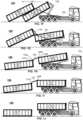
Figures 1A-1J illustrate a principle of anexemplary interchanging arrangement 100 and method for interchanging first 101 and second 102 load units carried by avehicle 103 according to an advantageous embodiment of the invention, where inFigure 1A thevehicle 103 is bringing thefirst load unit 101 to the site and taking thesecond load unit 102 away. InFigures 1B-1D a movingdevice 104 moves and unloads thefirst load unit 101 from the vehicle in afirst direction 105, so backwards, and onto the top of thesecond load unit 102. The movingdevice 104 is as a traditional hook system, but may also be any other implementation, such as a chain, strap, belt or cable suitable for moving the load units. - In
Figure 1E the movingdevice 104 releases thefirst load unit 101 and grip thesecond load unit 102 below thefirst load unit 101. Also abraking system 108 can be attached to thefirst end 101A of the first load unit when thesecond load unit 102 is gripped for loading. InFigure 1F the movingdevice 104 moves and loads thesecond load unit 102 onto the vehicle so that thefirst load unit 101 slides on the top and along thesecond load unit 102 essentially in saidfirst direction 105 in relation to the second load unit during loading thesecond load unit 102 onto thevehicle 103. Thebraking system 108 slows or controls the sliding speed of thefirst load unit 101 along and on the top of thesecond load unit 102. There is advantageously a sliding path 109 (illustrated in more details inFigure 4 ) arranged into the top portion of thesecond load unit 102 along which thefirst load unit 101 is sliding. - The
first load unit 101 slides on the top (advantageously due to gravity, but also other mechanism can be implemented) and along thesecond load unit 102 advantageously until thefirst end 101A of thefirst load unit 101 meets and/or passes thesecond end 102B of thesecond load unit 102, as is the case inFigure 1G (a portion of thelanding device 106 is illustrated as at least partially opened inFigure 1G but this is only for depicting the functional principle of the landing unit). When thefirst end 101A of thefirst load unit 101 meets and/or passes thesecond end 102B of thesecond load unit 102, alanding device 106 is advantageously activated between thefirst end 101A of thefirst load unit 101 and thesecond end 102B of the second load unit 102 (more details inFigures 6A-6C ). As an example afirst portion 106A (fixed portion) of thelanding device 106 is fixed to thefirst end portion 101A of the first load unit, whereupon asecond portion 106B (a free end portion) is configured to catch to thesecond end 102B of thesecond load unit 102. - When the
second load unit 102 is still moved towards and onto the vehicle (in the opposite direction of 105), thefree end 106B of thelanding device 106 is supported to thesecond end portion 102B of thesecond load unit 102, whereupon thelanding device 106 is configured to move thefirst end 101A of thefirst load unit 101 into the lower level than thesecond end 102B of thesecond load unit 102, advantageously to the ground, as is illustrated inFigures 1H-1J . - It is to be noted that the
braking system 108 can be used for controlling the sliding speed of thefirst load unit 101 when it slides on the top and along thesecond load unit 102 during the loading of thesecond load unit 102 onto thevehicle 103. Thebraking system 108 is released from thefirst unit 101 at the latest after thefirst end 101A of thefirst load unit 101 has met and passed thesecond end 102B of thesecond load unit 102. According to an example thefirst end 108A of thebraking system 108 can be coupled to thesecond load unit 102 or to thevehicle 103 and thesecond end 108B of thebraking system 108 to thefirst unit 101 and in particularly to thefirst end 101A of saidfirst unit 101, as is illustrated inFigure 2C . - An
exemplary braking system 108 illustrated inFigures 1G and2C is implemented by acable 108, the unwinding of which can be controlled by acontrollable motor 110, such as by a hydraulic or electric motor, for example. However, it is to be noted that according to an exemplary embodiment and especially when the other end of the cable is fixed to the vehicle, there might be no need for controlling the length (unwinding or winding) the cable, but the cable may have a certain fixed length arranged so that when the load unit is unloaded e.g. by atraditional hook system 104, the trajectory of thefirst end 101A of thefirst load unit 101 is arranged to that the fixed length of the cable is enough. This can be applied also for landing or lowering process of thefirst end 101A of thefirst load unit 101 for example because thefirst end 101A does not essentially move in relation to the ground or vehicle in thedirection 105 anymore when it is lowered. - The
braking system 108 can also be implemented by other systems, such as a spring or a brake cylinder, such as a pneumatic or hydraulic cylinder, which is configured to control the sliding speed of the first load unit by the spring force or via force induced by the brake cylinder. In addition the braking system may also comprise a friction brake or other braking system suitable and known by the skilled person, such as an elongated arm, like a rod or bar. -
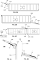
Figures 2A-2C and Figures 3A-3B illustrateexemplary interchanging arrangements 100 according to an advantageous embodiment of the invention, where inFigures 2A and 3A thelanding device 106 is integrated to thefirst end 101A of thefirst load unit 101, and inFigures 2B and 3B thelanding device 106 is integrated to thesecond end 102B of thesecond load unit 102. - In the example of
Figures 2A and 3A (corresponding essentially the arrangement andmethod 100 illustrated inFigures 1A-1J ) afirstportion 106A of thelanding device 106 is integrally fixed to thefirst end 101A of thefirst load unit 101, whereupon the secondfree portion 106B of thelanding device 106 is configured to catch and to be supported to thesecond end 102B of thesecond load unit 102, when thefirst end 101A of thefirst load unit 101 is passed thesecond end 102B of the second load unit into thefirst direction 105, as is the case inFigures 1G-1H . - Alternatively, as can be seen in
Figures 2B and 3B thefirst portion 106A of thelanding device 106 can also be integrally fixed to thesecond end 102B of thesecond load unit 102, whereupon the secondfree portion 106B of the landing device is configured to catch and to be supported to thefirst end 101A of thefirst load unit 101, when thefirst end 101A of thefirst load unit 101 is passed thesecond end 102B of the second load unit into the first direction 105 (corresponding the situation illustrated inFigures 1G-1H ). - The first and
second portions second portions landing device 106 is activated and is moving or lowering thefirst end 101A of thefirst load unit 101 to the ground. Thelanding device 106 advantageously comprises abraking member 107 configured to apply force resisting the movement of the first andsecond portions second portions first end 101A of thefirst load unit 101. -
Figure 2C illustrates another example, where thelanding device 106 with the brakingmember 107 is implemented by a cable, the unwinding and/or rewinding of which can be controlled. In the embodiment thefirst portion 107A of the cable is supported or coupled to thesecond end 102B of thesecond load unit 102 and thesecond portion 107B of the cable is supported or coupled to thefirst end 101A of thefirst load unit 101. According to an embodiment there is provided asupport point 102C to thesecond end 102B for supporting thefirst portion 107A of the cable, advantageously to the upper portion of the second end of the second load unit. The unwinding and/or rewinding of thecable 107 can be controlled e.g. by amotor 110, to which the first end 107AA of the cable is coupled with. Also other mechanism can be used. By controlling the unwinding and/or rewinding of thecable 107 the mowing or lowering speed of thefirst end 101A of the first load unit can be managed and controlled. - According to an example the cable 107 (or the like) can be configured to function both as a
braking system 108 for controlling the sliding speed of thefirst load unit 101 when it slides on the top and along thesecond load unit 102 during the loading of thesecond load unit 102 onto the vehicle, but also as thebraking member 107 for slowing down the landing of thefirst end 101A of thefirst load unit 101 after thefirst end 101A of thefirst load unit 101 has met and passed thesecond end 102B of thesecond load unit 102. According to an advantageous embodiment thecable 107/108 (one and same cable for two different functions) can be first connected to thefirst end 101A of thefirst load unit 101 via thesupport point 102C, after which thecable 107/108 automatically functions as thebraking member 107 after thefirst end 101A of thefirst load unit 101 has met and passed thesecond end 102B of thesecond load unit 102 -
Figures 3A and 3B still illustrate more detailed embodiment of thelanding device 106 and thebraking member 107. The brakingmember 107 can be implemented by or provided with e.g. a brake cylinder, such as a pneumatic or hydraulic cylinder or a spring or a mechanical construction, such as a friction brake. In addition also an electric or hydraulic motor can be used for braking of resisting the movement of thefirst end 101A of thefirst load unit 101 towards the ground. As an example acable 107 can be attached to the first load unit 101 (as is illustrated inFigure 2C ) and in particularly to thefirst end 101A of thefirst load 101 unit so that it 101A/101 can be moved downwards in a controllable manner, such as unwinding thecable 107 by themotor 110 or the like. According to an embodiment the braking device is configured to be operated in a controllable manner. - According to an example the operation of the
braking member 107 can be controlled, whereupon the moving or lowering speed of thefirst end 101A of thefirst load unit 101 can be controlled advantageously in a stepless way and so that thefirst end 101A of thefirst load unit 101 is lowered e.g. to the ground in a safe and controlled manner. -
Figure 4A illustrates a section view of anexemplary load unit path 109 according to an advantageous embodiment of the invention, wherein the slidingpath 109 is configured to receive and allow anotherload unit path 109 in thefirst direction 105 or in parallel to the longitudinal axis of the load unit and in relation to thelower load unit 101 during loading or unloading theload units vehicle 103. The slidingpath 109 comprises e.g. a rail or groove and it is advantageously arranged into the top portion of theload unit 101. Alternatively it can also be arranged to the bottom portion of theload unit 102. - The
load unit 101 sliding along the slidingpath 109 advantageously comprises a slidingmember 111, such as a wheel or slide or ski or the like. It is to be noted the slidingmember 111 is advantageously arranged to thelanding device 106 as can be seen in more details inFigures 5A-5B and6A-6C . In addition it is to be noted that the slidingmember 111 may be arranged to the both sides of the slidingpath 109, whereupon the slidingpath 109 together the slidingmember 111 will lock or secure theload unit 101 sliding along the slidingpath 109 to theload unit 102 locating below the slidingload unit 101. -
Figure 4B illustrates another example of the slidingpath 109, where the sliding path is implemented with a rail orbar 109. Thefirst load unit 101 sliding along the slidingpath 109 comprises a receivingstructure 116 forming a groove or slot for receiving the slidingpath 109 into the receivingstructure 116. The receivingstructure 116 can be formed e.g. by the base structure of thefirst load unit 101, for example a bottom portion of thefirst load unit 101 together with the slidingmember 111 arranged to the structure of the first load unit. -
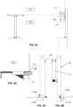
Figures 5A-5B illustrate side and front views of anexemplary landing device 106 with abraking member 107 according to an advantageous embodiment of the invention, where the slidingmember 111 can be clearly seen. The exemplary slidingmember 111 comprises two wheels where thefirst wheel 111A is configured to be coupled below the slidingpath 109 and thesecond wheel 111B is configured to be coupled above the slidingpath 109. -
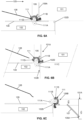
Figures 6A-6C illustrate a principle of alanding device 106 with abraking member 107 according to an advantageous embodiment of the invention. InFigures 6A-6C thefirst load unit 101 is sliding on the top of thesecond load unit 102 along the slidingpath 109 in thedirection 105. Thebraking system 108 is also used (optional) to resist the free sliding of thefirst load unit 101 as is disclosed elsewhere in this document. Thesecond end 108B of thebraking system 108 is coupled to thefirst unit 101 and the sliding speed of the first load unit along the slidingpath 109 is controlled advantageously by a controlling device, such as a motor. In addition the controlling device can be implemented by other system known by the skilled person. - In the embodiment illustrated on
Figures 6A-6C thefirst portion 106A of thelanding device 106 is fixed to thefirst end portion 101A of thefirst load unit 101. When thefirst end 101A of thefirst load unit 101 or in more details the slidingmember 111 has met and/or passed thesecond end 102B of thesecond load unit 102 or the supportingpoint 102D, thesecond portion 106B of thelanding device 106 is configured to stop to thesecond end 102B of thesecond load unit 102 or the supportingpoint 102D and configured to be supported by the supportingpoint 102D and turn around the supportingpoint 102D so that the angle between the first andsecond portions landing device 106 is opened. The opening is advantageously resisted by the brakingmember 107 between the first andsecond portions - When the
first end 101A of thefirst load unit 101 has met thesecond end 102B of thesecond load unit 102, the slidingmember 111 is configured to be turned around the supportingpoint 102D (to the clockwise in theFigures 6A-6C ). At the sametime coupling member 111D is configured to turn and release the braking system 108 (a cable in the embodiment inFigures 6A-6C ), if used, from the slidingmember 111 and thereby also from thefirst load unit 101. - Again, when the
second load unit 102 is loaded onto thevehicle 103, thelanding device 106 moves or lowers thefirst end 101A of thefirst load unit 101 to the ground or at least to the lower level than thesecond end 102B of thesecond load unit 102. When the opening angle between the first andsecond portions second end 106B of the landing device or in practise the slidingmember 111 has turned over a threshold angle around the supportingpoint 102D, thesecond end 106B will be released from the contact of thesecond end 102B or the supportingpoint 102D of thesecond load unit 102. Thus thelanding device 106 is configured to be uncoupled after thefirst end 101A of thefirst load unit 101 is moved into the lower level than thesecond end 102B of thesecond load unit 102. -
Figures 7A-7H illustrate examples of the slidingpath structure 109 for guiding theload units Figures 7A-H thesecond load unit 102 comprises the slidingpath 109 and additionally the lockingmember 112 for stopping the sliding of the first load unit 101 (shown in particularly inFigures 7C-7G ) when it slides on the slidingpath 109. - The locking
member 112 advantageously comprises a deflectingmember 113, such as awedge ramp 113, for deflecting the slidingmember 111 of thefirst load unit 101 against a stopping member 114 (Figures 7C-7G ), when thefirst load unit 101 slides on the slidingpath 109. Thefirst load unit 101 comprises advantageously the slidingmember 111, as is described for example in connection withFigure 4B . The slidingmember 111 slides along the slidingpath 109 until it is deflected by the deflectingmember 113 so that the slidingmember 111 meets the lockingmember 112 and thereby stops the sliding. - In more details the position of the locking
member 112 can be adjusted in relation to thesecond load unit 102 advantageously in adirection 119 so that the deflectingmember 113 will deflect the slidingmember 111 when the center of gravity of thefirst load unit 101 is passed thesecond end portion 102B of thesecond load unit 102, whereupon thefirst end portion 101A and thus also the slidingmember 111 is skipped upwards and against the stoppingmember 114. The locking member may comprise number of stoppingmembers 114 both in the upper and lower portions of the slidingpath 109. - The
first load unit 101 can slide further in relation to thesecond load unit 102 in thedirection 119 when the slidingmember 111 is passed the stoppingmembers 114 e.g. by moving thefirst end 101A and thus also the slidingmember 111 as is described elsewhere in this document and in particularly inFigures 7C-7G . - The stopping
member 112 may comprise also ashock absorption mechanism 118 for absorbing kinetic energy of thefirst load unit 101 when stopping the movement of said first load unit. - In addition the
second load unit 102 may comprise anintroduction member 115 at an end portion of thesecond end 102B of thesecond load unit 102, as is described inFigure 7H . Theintroduction member 115 introduces thefirst end 101A of thefirst load unit 101 to thelanding device 106. For this theintroduction member 115 comprise e.g. adeflection member 117, which will deflect thefirst end 101A of thefirst load unit 101 or the slidingmember 111 of thefirst load unit 101 so that it better meets thelanding device 106. -
Figures 8A-8C illustrate examples of theload units Figure 8A a side view of oneload unit 101 is illustrated. InFigure 8B thefirst load unit 101 is stacked or loaded on the top of thesecond load unit 102, advantageously via the slidingpath 109.Figure 8C illustrates a front view of the stackedload units braking member 107 of the landing device is also shown. - The invention has been explained above with reference to the aforementioned embodiments, and several advantages of the invention have been demonstrated. It is clear that the invention is not only restricted to these embodiments, but comprises all possible embodiments within the spirit and scope of the inventive thought and the following patent claims. For example a cable is demonstrated as an example of the
braking member 107 andsystem 108, but also other types of suitable devices can be used, such as belt, strap or chain, for example. - In addition, even if only two load units are demonstrated in Figures, they are only examples and also more than two load units can be loaded on top of each other and carried. Moreover it is to be noted that even if the load units depicted in Figures have the side wall and/or end walls, the side and/or end walls are however not essential, but e.g. the load unit can be implemented also as a platform with just ends (101A, 101B, 102A, 102B) and without actual walls.
- The features recited in dependent claims are mutually freely combinable unless otherwise explicitly stated.
Claims (15)
- An interchanging arrangement (100) for interchanging at least first (101) and second (102) load units carried by a vehicle (103), both of said load units having first and second ends (101A, 101B, 102A, 102B),wherein the arrangement comprises:- a landing device (106) arranged between the first end (101A) of the first load unit (101) and the second end (102B) of the second load unit (102) so that a first portion (106A) of said landing device (106) is supported to the first end (101A) of the first load unit (101) and a second portion (106B) of said landing device (106) is supported to the second end (102B) of the second load unit (102) for interchanging said load units,- a moving device (104) arranged for moving and unloading the first load unit (101) from the vehicle in a first direction (105) and onto the top of the second load unit (102) located next to the vehicle,characterized in that,- said moving device is further arranged for releasing the first load unit (101), and for gripping the second load unit (102) below the first load unit (101) and moving and loading said second load unit (102) onto the vehicle so that said first load unit (101) is still on the top of the second load unit (102) at the beginning of the moving of the second load unit (102) and so that said first load unit (101) slides on the top and along the second load unit (102) in said first direction (105) during loading said second load unit (102) onto the vehicle (103) until the first end (101A) of the first load unit (101) meets the second end (102B) of the second load unit (102), and- said landing device (106) is configured to move said first end (101A) of said first load unit (101) into a lower level than the second end (102B) of the second load unit (102) after said first end (101A) of the first load unit (101) has met said second end (102B) of the second load unit (102).
- The interchanging arrangement of claim 1, wherein said arrangement (100) or said landing device (106) comprises a braking member (107) to slow down the landing of said first end (101A) of said first load unit (101), where said landing device (106) comprises a first portion (106A) coupled to the end portion (101A, 101B, 102A, 102B) of the load unit (101, 102) and a second portion (106B) coupled, such as hinged, with said first portion (106A) of said landing device (106), and wherein said landing device (106) comprises braking member (107) arranged between said first and second portions (106A, 106B) of said landing device (106), said braking member (107) configured to apply force resisting to move said first and second portions (106A, 106B) of said landing device (106) farther from each other..
- The interchanging arrangement of claim 2, wherein said braking member (107) comprises a spring or a brake cylinder, such as a pneumatic or hydraulic cylinder or a cable the unwinding of which is controlled, the first end of said braking member being coupled with the first portion (106A) of said landing device (106) and the second end of said braking member (107) being coupled with the second portion (106B) of said landing device (106), or wherein the braking member (107) comprises a friction brake.
- The interchanging arrangement of any claims 2-3, wherein the first portion (106A) of the landing device (106) is fixed:- to the first end portion (101A) of the first load unit (101), whereupon the second portion (106B) of the landing device (106) is configured to be coupled to the second end portion (102B) of the second load unit (102) after said first end (101A) of the first load unit (101) has met and passed said second end (102B) of the second load unit (102), or- to the second end portion (102B) of the second load unit (102), whereupon the second portion (106B) of the landing device (106) is configured to be coupled to the first end portion (101A) of the first load unit (101) after said first end (101A) of the first load unit (101) has met and passed said second end (102B) of the second load unit (102).
- The interchanging arrangement of any previous claims, wherein the arrangement comprises a braking system (108) configured to control the sliding speed of the first load unit (101) when it slides on the top and along the second load unit (102) during the loading said second load unit (102) onto the vehicle (103), where the first end (108A) of the braking system (108) is coupled to the second load unit (102) or to the vehicle (103) and the second end (108B) of the braking system (108) is coupled to the first unit (101) and in particularly to the first end (101A) of said first unit (101).
- The interchanging arrangement of claim 5, wherein the braking system (108) comprises a spring or a brake cylinder, such as a pneumatic or hydraulic cylinder, configured to control the sliding speed by the spring force or via force induced by the brake cylinder, or wherein the braking system comprises a cable, with a fixed length or a cable the unwinding of which is controlled by a controllable motor or wherein the braking system comprises a friction brake or wherein the braking system (108) is an elongated arm, such as a rod or bar.
- The interchanging arrangement of claim 2, wherein said braking member (107) comprises a cable, where the first portion (107A) of said cable is supported or coupled to the second end (102B) of the second load unit (102) and the second portion (107B) of said cable is supported or coupled to the first end (101A) of the first load unit (101).
- The interchanging arrangement of claims 7, wherein the braking member (107) comprises a controllable motor, which is configured to control the unwinding of the cable and thereby slow down the landing of said first end (101A) of said first load unit (101).
- The interchanging arrangement of claims 7 or 8, wherein said cable (107) is in addition configured to function as a braking system (108) for controlling the sliding speed of the first load unit (101) when it slides on the top and along the second load unit (102) during the loading said second load unit (102) onto the vehicle, and after said first end (101A) of the first load unit (101) has met and passed said second end (102B) of the second load unit (102) said cable is in addition configured to function as said braking member (107) for slowing down the landing of said first end (101A) of said first load unit (101).
- The interchanging arrangement of any previous claims, wherein the load unit (101, 102) comprises a sliding path (109) to receive and allow another load unit (101, 102) to slide along said sliding path (109) during loading or unloading said load (101, 102) unit onto or from the vehicle, and wherein in particularly the second load unit (102) comprises the sliding path (109) and a locking member (112) arranged in connection with the sliding path (109), and the first load unit comprises a sliding member (111) configured to slide along said sliding path (109), wherein said locking member (112) is configured to stop the sliding of the first load unit (101) via an interaction with said sliding member (111) of the first load unit (101), when it slides on the sliding path (109).
- The interchanging arrangement of claim 10, wherein the locking member (112) comprises a wedge ramp (113) for deflecting the sliding member (111) of the first load unit (101) against a stopping member (114) when the first load unit (101) slides on the sliding path (109).
- The interchanging arrangement of any previous claims, wherein the second load unit (101, 102) comprises an introduction member (115) at an end portion of the second end (102B) of the second load unit (102), where said introduction member (115) is configured to introduce the first end (101A) of said first load unit (101) to the landing device (106) after said first end (101A) of the first load unit (101) has met said second end (102B) of the second load unit (102) and thereby allowing the moving of said first end (101A) of said first load unit (101) into the lower level than the second end (102B) of the second load unit (102).
- A load unit (101, 102) to be interchanged by the interchanging arrangement (100) of any of previous claims, wherein the load unit comprises the interchanging arrangement of any of previous claims.
- A vehicle comprising an interchanging arrangement according to any of previous claim 1-13 for interchanging at least first and second load units carried by the vehicle.
- A method for interchanging at least first (101) and second (102) load units carried by a vehicle (103), both of said load units (101, 102) having first and second ends (101A, 101B, 102A, 102B),wherein the method comprises steps of:- supporting a first portion (106A) of a landing device (106) to the first end (101A) of the first load unit (101) and a second portion (106B) of said landing device (106) to the second end (102B) of the second load unit (102) for interchanging said load units,- moving by a moving device (104) and unloading the first load unit (101) from the vehicle in a first direction (105) and onto the top of the second load unit (102) located next to the vehicle,characterized in that,- after releasing the first load unit (101), the second load unit (102) is gripped below the first load unit (101) and moved and loaded onto the vehicle by said moving device (104) so that said first load unit (101) is still on the top of the second load unit (102) at the beginning of the moving of the second load unit (102) and so that said first load unit (101) slides on the top and along the second load unit (102) in said first direction (105) during loading said second load unit (102) onto the vehicle (103) until the first end (101A) of the first load unit (101) meets the second end (102B) of the second load unit (102), and- moving the first end (101A) of said first load unit (101) into a lower level than the second end (102B) of the second load unit (102) after the first end (101A) of the first load unit (101) has met said second end (102B) of the second load unit (102).
Applications Claiming Priority (2)
| Application Number | Priority Date | Filing Date | Title |
|---|---|---|---|
| FI20175337A FI127476B (en) | 2017-04-11 | 2017-04-11 | Interchanging method and arrangement for interchanging load units |
| PCT/FI2017/050577 WO2017182719A2 (en) | 2017-04-11 | 2017-08-16 | Interchanging method and arrangement for interchanging load units |
Publications (3)
| Publication Number | Publication Date |
|---|---|
| EP3609739A2 EP3609739A2 (en) | 2020-02-19 |
| EP3609739A4 EP3609739A4 (en) | 2020-12-23 |
| EP3609739B1 true EP3609739B1 (en) | 2023-03-15 |
Family
ID=60115725
Family Applications (1)
| Application Number | Title | Priority Date | Filing Date |
|---|---|---|---|
| EP17785516.0A Active EP3609739B1 (en) | 2017-04-11 | 2017-08-16 | Interchanging method and arrangement for interchanging load units |
Country Status (12)
| Country | Link |
|---|---|
| US (1) | US11312286B2 (en) |
| EP (1) | EP3609739B1 (en) |
| JP (1) | JP6929440B2 (en) |
| KR (1) | KR102380698B1 (en) |
| CN (1) | CN110709280B (en) |
| CA (1) | CA3059834A1 (en) |
| FI (1) | FI127476B (en) |
| PL (1) | PL3609739T3 (en) |
| RU (1) | RU2748932C2 (en) |
| SA (1) | SA519410283B1 (en) |
| SG (1) | SG11201909425XA (en) |
| WO (1) | WO2017182719A2 (en) |
Families Citing this family (6)
| Publication number | Priority date | Publication date | Assignee | Title |
|---|---|---|---|---|
| FI127894B (en) * | 2018-05-17 | 2019-05-15 | Delete Finland Oy | Load unit arrangement for connecting and disconnecting load units of the load unit arrangement |
| FI127897B (en) * | 2018-05-17 | 2019-05-15 | Delete Finland Oy | A load unit arrangement with a braking arrangement |
| FI127896B (en) * | 2018-05-17 | 2019-05-15 | Delete Finland Oy | A load unit arrangement having a guiding member for guiding the load unit when connected or disconnected |
| FI128747B (en) * | 2019-05-15 | 2020-11-30 | Delete Finland Oy | Pallet unit system for connecting and separating pallet units of a pallet unit system |
| FI129662B (en) * | 2019-08-12 | 2022-06-15 | Delete Finland Oy | Load unit arrangement for connection and disconnection of load units included in the load unit arrangement |
| FI129458B (en) * | 2020-06-18 | 2022-02-28 | Contle Oy | LOADING SYSTEM FOR LOADING LOAD UNITS ON AND OF A VEHICLE |
Family Cites Families (23)
| Publication number | Priority date | Publication date | Assignee | Title |
|---|---|---|---|---|
| US2305148A (en) * | 1940-09-20 | 1942-12-15 | George R Dempster | Transporting and dumping device |
| US3404793A (en) * | 1966-06-07 | 1968-10-08 | Albert A. Pinkert | Load carrier |
| DE1814242C3 (en) * | 1968-12-12 | 1974-05-09 | Licentia Patent-Verwaltungs-Gmbh, 6000 Frankfurt | Method and device for unloading or loading several hollow bodies, in particular pontoons, stacked on top of one another on a vehicle loading area |
| FI61151C (en) * | 1979-11-12 | 1982-06-10 | Urpo Hannonen | FOERFARANDE FOER TRANSPORTERING AV FLYTTBART FLAK OCH FLYTTBART FLAK |
| DE3731599A1 (en) * | 1987-09-19 | 1989-04-06 | Gutehoffnungshuette Man | METHOD AND DEVICE FOR CHANGING TOWS IN CHANGER TIPPERS |
| US5085448A (en) | 1990-06-13 | 1992-02-04 | Shubin Don B | Stackable containers |
| RU2020088C1 (en) * | 1991-06-04 | 1994-09-30 | Валентин Михайлович Таран | Transfer loader |
| DE19526605C2 (en) * | 1995-07-21 | 1998-07-16 | Juergen Boehlkau | Device for loading a first container onto a motor vehicle and for unloading a second empty container from this motor vehicle |
| WO1997030868A2 (en) | 1996-02-23 | 1997-08-28 | MÜHLBAUER, Rainer | Utility vehicle and transport unit system compatible with known transport systems |
| JP3148740B2 (en) * | 1999-05-21 | 2001-03-26 | シンコー株式会社 | Container-only vehicles, containers and loading / unloading methods |
| JP4106405B2 (en) * | 2002-03-05 | 2008-06-25 | 博人 齋藤 | Container stacking method and container stacking aid |
| ATE442973T1 (en) | 2002-10-25 | 2009-10-15 | Thomas Herwig | DEVICE AND METHOD FOR CHANGING BULK TUMPS |
| DE10325373A1 (en) | 2003-05-27 | 2005-01-05 | Herwig, Thomas B. | Lorry-mounted skip loader and unloader includes both longitudinal- and vertical displacers |
| DE10311359A1 (en) * | 2003-03-14 | 2004-10-07 | Manfred Schaich | Container handling device for a container transport vehicle |
| EP2111349A4 (en) * | 2007-02-02 | 2010-05-12 | William Chester Cline | Loading and unloading arrangement for a vehicle |
| CA2590853A1 (en) * | 2007-06-07 | 2008-12-07 | Rino Beaulieu | Truck transportable carrier and method of loading the same onto a truck for transport |
| FR2919544B1 (en) | 2007-08-03 | 2009-10-30 | Christophe Gaussin | AUTOMOTIVE VEHICLE CLEAN OF HEAVY TRANSPORT, IN PARTICULAR PORT |
| RU72916U1 (en) * | 2007-12-26 | 2008-05-10 | Сергей Петрович Семенищев | MOBILE GAS FILLER CONTAINER TYPE |
| JP5380159B2 (en) | 2009-05-28 | 2014-01-08 | 極東開発工業株式会社 | Cargo handling vehicle |
| DE102014107144B3 (en) * | 2014-05-21 | 2015-06-25 | Peter B. Ellebracht | Lifting means for stackable deposit containers |
| JP6543089B2 (en) * | 2015-05-22 | 2019-07-10 | 極東開発工業株式会社 | Cargo handling vehicle |
| CN204675178U (en) | 2015-05-27 | 2015-09-30 | 河南凯达汽车有限公司 | The visual rubbish compartment of double door |
| US10322874B1 (en) * | 2016-04-13 | 2019-06-18 | Mark D. Curley | Dumpster handling device and method |
-
2017
- 2017-04-11 FI FI20175337A patent/FI127476B/en active
- 2017-08-16 US US16/604,556 patent/US11312286B2/en active Active
- 2017-08-16 KR KR1020197033347A patent/KR102380698B1/en active Active
- 2017-08-16 PL PL17785516.0T patent/PL3609739T3/en unknown
- 2017-08-16 WO PCT/FI2017/050577 patent/WO2017182719A2/en not_active Ceased
- 2017-08-16 RU RU2019136155A patent/RU2748932C2/en active
- 2017-08-16 SG SG11201909425X patent/SG11201909425XA/en unknown
- 2017-08-16 CA CA3059834A patent/CA3059834A1/en active Pending
- 2017-08-16 JP JP2020505536A patent/JP6929440B2/en active Active
- 2017-08-16 CN CN201780091483.2A patent/CN110709280B/en active Active
- 2017-08-16 EP EP17785516.0A patent/EP3609739B1/en active Active
-
2019
- 2019-10-10 SA SA519410283A patent/SA519410283B1/en unknown
Also Published As
| Publication number | Publication date |
|---|---|
| WO2017182719A3 (en) | 2018-01-04 |
| SA519410283B1 (en) | 2022-05-11 |
| RU2019136155A3 (en) | 2021-05-11 |
| KR20200003383A (en) | 2020-01-09 |
| US11312286B2 (en) | 2022-04-26 |
| RU2019136155A (en) | 2021-05-11 |
| WO2017182719A2 (en) | 2017-10-26 |
| CN110709280B (en) | 2022-06-17 |
| EP3609739A4 (en) | 2020-12-23 |
| KR102380698B1 (en) | 2022-03-29 |
| PL3609739T3 (en) | 2023-07-17 |
| JP2020516542A (en) | 2020-06-11 |
| CA3059834A1 (en) | 2017-10-26 |
| EP3609739A2 (en) | 2020-02-19 |
| CN110709280A (en) | 2020-01-17 |
| US20210114829A1 (en) | 2021-04-22 |
| JP6929440B2 (en) | 2021-09-01 |
| SG11201909425XA (en) | 2019-11-28 |
| FI127476B (en) | 2018-06-29 |
| RU2748932C2 (en) | 2021-06-01 |
Similar Documents
| Publication | Publication Date | Title |
|---|---|---|
| EP3609739B1 (en) | Interchanging method and arrangement for interchanging load units | |
| CN101181956B (en) | Article transport facility | |
| US5577597A (en) | Work transport system including pallet transport apparatus | |
| US20160325928A1 (en) | A locking apparatus and a securing mechanism therein | |
| CN101181957B (en) | Article carrying apparatus | |
| CN109715526B (en) | Device for clamping variable-size loads and corresponding method for adjusting clamping width | |
| US5320473A (en) | Transfer apparatus, multilevel storage system and method of lifting loads | |
| JPH05254649A (en) | Sorting apparatus for small object | |
| KR20180056640A (en) | The elevator carriage operating device and the elevator carriage | |
| CN109760574B (en) | Transport vehicle based on intelligent transportation and working method thereof | |
| CN115989159A (en) | Vehicle with load compartment | |
| JP2011079657A (en) | Transfer device and transfer method | |
| JP2994263B2 (en) | Bicycle parking equipment | |
| CN114314437B (en) | Tray removing device and feeding system | |
| EP1499516A1 (en) | Load moving device for transport vehicles | |
| CN111807267B (en) | Method for transferring material box with unknown gravity center by using forklift | |
| FI75121C (en) | Procedure for loading replacement flasks. | |
| JPH072368A (en) | Truck loader | |
| CN119142259B (en) | Vehicle-mounted intelligent robot of unmanned automobile | |
| SE428786B (en) | DEVICE FOR PARALLEL CONTROLLED LIFT ARMS ON THE VEHICLE CHASSIS | |
| FI127897B (en) | A load unit arrangement with a braking arrangement | |
| JP2512682B2 (en) | Truck loader | |
| JP7134475B2 (en) | Movable floor of gondola lift stop | |
| FI128747B (en) | Pallet unit system for connecting and separating pallet units of a pallet unit system | |
| JP2006143364A (en) | Article carrying device |
Legal Events
| Date | Code | Title | Description |
|---|---|---|---|
| STAA | Information on the status of an ep patent application or granted ep patent |
Free format text: STATUS: THE INTERNATIONAL PUBLICATION HAS BEEN MADE |
|
| PUAI | Public reference made under article 153(3) epc to a published international application that has entered the european phase |
Free format text: ORIGINAL CODE: 0009012 |
|
| STAA | Information on the status of an ep patent application or granted ep patent |
Free format text: STATUS: REQUEST FOR EXAMINATION WAS MADE |
|
| 17P | Request for examination filed |
Effective date: 20191025 |
|
| AK | Designated contracting states |
Kind code of ref document: A2 Designated state(s): AL AT BE BG CH CY CZ DE DK EE ES FI FR GB GR HR HU IE IS IT LI LT LU LV MC MK MT NL NO PL PT RO RS SE SI SK SM TR |
|
| AX | Request for extension of the european patent |
Extension state: BA ME |
|
| RAP1 | Party data changed (applicant data changed or rights of an application transferred) |
Owner name: DELETE DEMOLITION OY |
|
| DAV | Request for validation of the european patent (deleted) | ||
| DAX | Request for extension of the european patent (deleted) | ||
| A4 | Supplementary search report drawn up and despatched |
Effective date: 20201125 |
|
| RIC1 | Information provided on ipc code assigned before grant |
Ipc: B60P 1/64 20060101AFI20201119BHEP Ipc: B60P 1/48 20060101ALI20201119BHEP Ipc: B65F 3/00 20060101ALI20201119BHEP |
|
| RAP3 | Party data changed (applicant data changed or rights of an application transferred) |
Owner name: LOTUS DEMOLITION OY |
|
| GRAP | Despatch of communication of intention to grant a patent |
Free format text: ORIGINAL CODE: EPIDOSNIGR1 |
|
| STAA | Information on the status of an ep patent application or granted ep patent |
Free format text: STATUS: GRANT OF PATENT IS INTENDED |
|
| INTG | Intention to grant announced |
Effective date: 20221004 |
|
| GRAS | Grant fee paid |
Free format text: ORIGINAL CODE: EPIDOSNIGR3 |
|
| GRAA | (expected) grant |
Free format text: ORIGINAL CODE: 0009210 |
|
| STAA | Information on the status of an ep patent application or granted ep patent |
Free format text: STATUS: THE PATENT HAS BEEN GRANTED |
|
| AK | Designated contracting states |
Kind code of ref document: B1 Designated state(s): AL AT BE BG CH CY CZ DE DK EE ES FI FR GB GR HR HU IE IS IT LI LT LU LV MC MK MT NL NO PL PT RO RS SE SI SK SM TR |
|
| REG | Reference to a national code |
Ref country code: CH Ref legal event code: EP Ref country code: GB Ref legal event code: FG4D |
|
| REG | Reference to a national code |
Ref country code: DE Ref legal event code: R096 Ref document number: 602017066845 Country of ref document: DE |
|
| REG | Reference to a national code |
Ref country code: IE Ref legal event code: FG4D |
|
| REG | Reference to a national code |
Ref country code: AT Ref legal event code: REF Ref document number: 1553836 Country of ref document: AT Kind code of ref document: T Effective date: 20230415 |
|
| REG | Reference to a national code |
Ref country code: NL Ref legal event code: FP |
|
| REG | Reference to a national code |
Ref country code: SE Ref legal event code: TRGR |
|
| REG | Reference to a national code |
Ref country code: LT Ref legal event code: MG9D |
|
| PG25 | Lapsed in a contracting state [announced via postgrant information from national office to epo] |
Ref country code: RS Free format text: LAPSE BECAUSE OF FAILURE TO SUBMIT A TRANSLATION OF THE DESCRIPTION OR TO PAY THE FEE WITHIN THE PRESCRIBED TIME-LIMIT Effective date: 20230315 Ref country code: NO Free format text: LAPSE BECAUSE OF FAILURE TO SUBMIT A TRANSLATION OF THE DESCRIPTION OR TO PAY THE FEE WITHIN THE PRESCRIBED TIME-LIMIT Effective date: 20230615 Ref country code: LV Free format text: LAPSE BECAUSE OF FAILURE TO SUBMIT A TRANSLATION OF THE DESCRIPTION OR TO PAY THE FEE WITHIN THE PRESCRIBED TIME-LIMIT Effective date: 20230315 Ref country code: LT Free format text: LAPSE BECAUSE OF FAILURE TO SUBMIT A TRANSLATION OF THE DESCRIPTION OR TO PAY THE FEE WITHIN THE PRESCRIBED TIME-LIMIT Effective date: 20230315 Ref country code: HR Free format text: LAPSE BECAUSE OF FAILURE TO SUBMIT A TRANSLATION OF THE DESCRIPTION OR TO PAY THE FEE WITHIN THE PRESCRIBED TIME-LIMIT Effective date: 20230315 |
|
| REG | Reference to a national code |
Ref country code: AT Ref legal event code: MK05 Ref document number: 1553836 Country of ref document: AT Kind code of ref document: T Effective date: 20230315 |
|
| PG25 | Lapsed in a contracting state [announced via postgrant information from national office to epo] |
Ref country code: GR Free format text: LAPSE BECAUSE OF FAILURE TO SUBMIT A TRANSLATION OF THE DESCRIPTION OR TO PAY THE FEE WITHIN THE PRESCRIBED TIME-LIMIT Effective date: 20230616 Ref country code: FI Free format text: LAPSE BECAUSE OF FAILURE TO SUBMIT A TRANSLATION OF THE DESCRIPTION OR TO PAY THE FEE WITHIN THE PRESCRIBED TIME-LIMIT Effective date: 20230315 |
|
| PG25 | Lapsed in a contracting state [announced via postgrant information from national office to epo] |
Ref country code: SM Free format text: LAPSE BECAUSE OF FAILURE TO SUBMIT A TRANSLATION OF THE DESCRIPTION OR TO PAY THE FEE WITHIN THE PRESCRIBED TIME-LIMIT Effective date: 20230315 Ref country code: RO Free format text: LAPSE BECAUSE OF FAILURE TO SUBMIT A TRANSLATION OF THE DESCRIPTION OR TO PAY THE FEE WITHIN THE PRESCRIBED TIME-LIMIT Effective date: 20230315 Ref country code: PT Free format text: LAPSE BECAUSE OF FAILURE TO SUBMIT A TRANSLATION OF THE DESCRIPTION OR TO PAY THE FEE WITHIN THE PRESCRIBED TIME-LIMIT Effective date: 20230717 Ref country code: ES Free format text: LAPSE BECAUSE OF FAILURE TO SUBMIT A TRANSLATION OF THE DESCRIPTION OR TO PAY THE FEE WITHIN THE PRESCRIBED TIME-LIMIT Effective date: 20230315 Ref country code: EE Free format text: LAPSE BECAUSE OF FAILURE TO SUBMIT A TRANSLATION OF THE DESCRIPTION OR TO PAY THE FEE WITHIN THE PRESCRIBED TIME-LIMIT Effective date: 20230315 Ref country code: CZ Free format text: LAPSE BECAUSE OF FAILURE TO SUBMIT A TRANSLATION OF THE DESCRIPTION OR TO PAY THE FEE WITHIN THE PRESCRIBED TIME-LIMIT Effective date: 20230315 Ref country code: AT Free format text: LAPSE BECAUSE OF FAILURE TO SUBMIT A TRANSLATION OF THE DESCRIPTION OR TO PAY THE FEE WITHIN THE PRESCRIBED TIME-LIMIT Effective date: 20230315 |
|
| PG25 | Lapsed in a contracting state [announced via postgrant information from national office to epo] |
Ref country code: SK Free format text: LAPSE BECAUSE OF FAILURE TO SUBMIT A TRANSLATION OF THE DESCRIPTION OR TO PAY THE FEE WITHIN THE PRESCRIBED TIME-LIMIT Effective date: 20230315 Ref country code: IS Free format text: LAPSE BECAUSE OF FAILURE TO SUBMIT A TRANSLATION OF THE DESCRIPTION OR TO PAY THE FEE WITHIN THE PRESCRIBED TIME-LIMIT Effective date: 20230715 |
|
| REG | Reference to a national code |
Ref country code: DE Ref legal event code: R097 Ref document number: 602017066845 Country of ref document: DE |
|
| PLBE | No opposition filed within time limit |
Free format text: ORIGINAL CODE: 0009261 |
|
| STAA | Information on the status of an ep patent application or granted ep patent |
Free format text: STATUS: NO OPPOSITION FILED WITHIN TIME LIMIT |
|
| PG25 | Lapsed in a contracting state [announced via postgrant information from national office to epo] |
Ref country code: SI Free format text: LAPSE BECAUSE OF FAILURE TO SUBMIT A TRANSLATION OF THE DESCRIPTION OR TO PAY THE FEE WITHIN THE PRESCRIBED TIME-LIMIT Effective date: 20230315 Ref country code: DK Free format text: LAPSE BECAUSE OF FAILURE TO SUBMIT A TRANSLATION OF THE DESCRIPTION OR TO PAY THE FEE WITHIN THE PRESCRIBED TIME-LIMIT Effective date: 20230315 |
|
| 26N | No opposition filed |
Effective date: 20231218 |
|
| PG25 | Lapsed in a contracting state [announced via postgrant information from national office to epo] |
Ref country code: MC Free format text: LAPSE BECAUSE OF FAILURE TO SUBMIT A TRANSLATION OF THE DESCRIPTION OR TO PAY THE FEE WITHIN THE PRESCRIBED TIME-LIMIT Effective date: 20230315 |
|
| REG | Reference to a national code |
Ref country code: CH Ref legal event code: PL |
|
| PG25 | Lapsed in a contracting state [announced via postgrant information from national office to epo] |
Ref country code: MC Free format text: LAPSE BECAUSE OF FAILURE TO SUBMIT A TRANSLATION OF THE DESCRIPTION OR TO PAY THE FEE WITHIN THE PRESCRIBED TIME-LIMIT Effective date: 20230315 |
|
| PG25 | Lapsed in a contracting state [announced via postgrant information from national office to epo] |
Ref country code: LU Free format text: LAPSE BECAUSE OF NON-PAYMENT OF DUE FEES Effective date: 20230816 |
|
| PG25 | Lapsed in a contracting state [announced via postgrant information from national office to epo] |
Ref country code: LU Free format text: LAPSE BECAUSE OF NON-PAYMENT OF DUE FEES Effective date: 20230816 Ref country code: CH Free format text: LAPSE BECAUSE OF NON-PAYMENT OF DUE FEES Effective date: 20230831 |
|
| PG25 | Lapsed in a contracting state [announced via postgrant information from national office to epo] |
Ref country code: IT Free format text: LAPSE BECAUSE OF FAILURE TO SUBMIT A TRANSLATION OF THE DESCRIPTION OR TO PAY THE FEE WITHIN THE PRESCRIBED TIME-LIMIT Effective date: 20230315 |
|
| PG25 | Lapsed in a contracting state [announced via postgrant information from national office to epo] |
Ref country code: BG Free format text: LAPSE BECAUSE OF FAILURE TO SUBMIT A TRANSLATION OF THE DESCRIPTION OR TO PAY THE FEE WITHIN THE PRESCRIBED TIME-LIMIT Effective date: 20230315 |
|
| PG25 | Lapsed in a contracting state [announced via postgrant information from national office to epo] |
Ref country code: BG Free format text: LAPSE BECAUSE OF FAILURE TO SUBMIT A TRANSLATION OF THE DESCRIPTION OR TO PAY THE FEE WITHIN THE PRESCRIBED TIME-LIMIT Effective date: 20230315 |
|
| PG25 | Lapsed in a contracting state [announced via postgrant information from national office to epo] |
Ref country code: CY Free format text: LAPSE BECAUSE OF FAILURE TO SUBMIT A TRANSLATION OF THE DESCRIPTION OR TO PAY THE FEE WITHIN THE PRESCRIBED TIME-LIMIT; INVALID AB INITIO Effective date: 20170816 |
|
| PG25 | Lapsed in a contracting state [announced via postgrant information from national office to epo] |
Ref country code: HU Free format text: LAPSE BECAUSE OF FAILURE TO SUBMIT A TRANSLATION OF THE DESCRIPTION OR TO PAY THE FEE WITHIN THE PRESCRIBED TIME-LIMIT; INVALID AB INITIO Effective date: 20170816 |
|
| PGFP | Annual fee paid to national office [announced via postgrant information from national office to epo] |
Ref country code: NL Payment date: 20250818 Year of fee payment: 9 |
|
| PGFP | Annual fee paid to national office [announced via postgrant information from national office to epo] |
Ref country code: DE Payment date: 20250819 Year of fee payment: 9 |
|
| PGFP | Annual fee paid to national office [announced via postgrant information from national office to epo] |
Ref country code: TR Payment date: 20250728 Year of fee payment: 9 Ref country code: PL Payment date: 20250718 Year of fee payment: 9 |
|
| PGFP | Annual fee paid to national office [announced via postgrant information from national office to epo] |
Ref country code: BE Payment date: 20250818 Year of fee payment: 9 Ref country code: GB Payment date: 20250819 Year of fee payment: 9 |
|
| PGFP | Annual fee paid to national office [announced via postgrant information from national office to epo] |
Ref country code: FR Payment date: 20250818 Year of fee payment: 9 |
|
| PGFP | Annual fee paid to national office [announced via postgrant information from national office to epo] |
Ref country code: SE Payment date: 20250819 Year of fee payment: 9 |
|
| PGFP | Annual fee paid to national office [announced via postgrant information from national office to epo] |
Ref country code: IE Payment date: 20250818 Year of fee payment: 9 |