EP3609671B1 - Moulding method and apparatus - Google Patents
Moulding method and apparatus Download PDFInfo
- Publication number
- EP3609671B1 EP3609671B1 EP18704290.8A EP18704290A EP3609671B1 EP 3609671 B1 EP3609671 B1 EP 3609671B1 EP 18704290 A EP18704290 A EP 18704290A EP 3609671 B1 EP3609671 B1 EP 3609671B1
- Authority
- EP
- European Patent Office
- Prior art keywords
- main body
- pcr plate
- mould tool
- create
- polypropylene
- Prior art date
- Legal status (The legal status is an assumption and is not a legal conclusion. Google has not performed a legal analysis and makes no representation as to the accuracy of the status listed.)
- Active
Links
Images



Classifications
-
- B—PERFORMING OPERATIONS; TRANSPORTING
- B29—WORKING OF PLASTICS; WORKING OF SUBSTANCES IN A PLASTIC STATE IN GENERAL
- B29C—SHAPING OR JOINING OF PLASTICS; SHAPING OF MATERIAL IN A PLASTIC STATE, NOT OTHERWISE PROVIDED FOR; AFTER-TREATMENT OF THE SHAPED PRODUCTS, e.g. REPAIRING
- B29C45/00—Injection moulding, i.e. forcing the required volume of moulding material through a nozzle into a closed mould; Apparatus therefor
- B29C45/17—Component parts, details or accessories; Auxiliary operations
- B29C45/26—Moulds
- B29C45/2669—Moulds with means for removing excess material, e.g. with overflow cavities
-
- B—PERFORMING OPERATIONS; TRANSPORTING
- B29—WORKING OF PLASTICS; WORKING OF SUBSTANCES IN A PLASTIC STATE IN GENERAL
- B29C—SHAPING OR JOINING OF PLASTICS; SHAPING OF MATERIAL IN A PLASTIC STATE, NOT OTHERWISE PROVIDED FOR; AFTER-TREATMENT OF THE SHAPED PRODUCTS, e.g. REPAIRING
- B29C45/00—Injection moulding, i.e. forcing the required volume of moulding material through a nozzle into a closed mould; Apparatus therefor
- B29C45/17—Component parts, details or accessories; Auxiliary operations
- B29C45/1703—Introducing an auxiliary fluid into the mould
- B29C45/1704—Introducing an auxiliary fluid into the mould the fluid being introduced into the interior of the injected material which is still in a molten state, e.g. for producing hollow articles
- B29C45/1711—Introducing an auxiliary fluid into the mould the fluid being introduced into the interior of the injected material which is still in a molten state, e.g. for producing hollow articles and removing excess material from the mould cavity by the introduced fluid, e.g. to an overflow cavity
-
- B—PERFORMING OPERATIONS; TRANSPORTING
- B01—PHYSICAL OR CHEMICAL PROCESSES OR APPARATUS IN GENERAL
- B01L—CHEMICAL OR PHYSICAL LABORATORY APPARATUS FOR GENERAL USE
- B01L3/00—Containers or dishes for laboratory use, e.g. laboratory glassware; Droppers
- B01L3/50—Containers for the purpose of retaining a material to be analysed, e.g. test tubes
- B01L3/508—Rigid containers without fluid transport within
- B01L3/5085—Rigid containers without fluid transport within for multiple samples, e.g. microtitration plates
-
- B—PERFORMING OPERATIONS; TRANSPORTING
- B29—WORKING OF PLASTICS; WORKING OF SUBSTANCES IN A PLASTIC STATE IN GENERAL
- B29C—SHAPING OR JOINING OF PLASTICS; SHAPING OF MATERIAL IN A PLASTIC STATE, NOT OTHERWISE PROVIDED FOR; AFTER-TREATMENT OF THE SHAPED PRODUCTS, e.g. REPAIRING
- B29C45/00—Injection moulding, i.e. forcing the required volume of moulding material through a nozzle into a closed mould; Apparatus therefor
- B29C45/0046—Details relating to the filling pattern or flow paths or flow characteristics of moulding material in the mould cavity
-
- B—PERFORMING OPERATIONS; TRANSPORTING
- B01—PHYSICAL OR CHEMICAL PROCESSES OR APPARATUS IN GENERAL
- B01L—CHEMICAL OR PHYSICAL LABORATORY APPARATUS FOR GENERAL USE
- B01L2200/00—Solutions for specific problems relating to chemical or physical laboratory apparatus
- B01L2200/12—Specific details about manufacturing devices
-
- B—PERFORMING OPERATIONS; TRANSPORTING
- B01—PHYSICAL OR CHEMICAL PROCESSES OR APPARATUS IN GENERAL
- B01L—CHEMICAL OR PHYSICAL LABORATORY APPARATUS FOR GENERAL USE
- B01L2300/00—Additional constructional details
- B01L2300/08—Geometry, shape and general structure
- B01L2300/0809—Geometry, shape and general structure rectangular shaped
- B01L2300/0829—Multi-well plates; Microtitration plates
-
- B—PERFORMING OPERATIONS; TRANSPORTING
- B29—WORKING OF PLASTICS; WORKING OF SUBSTANCES IN A PLASTIC STATE IN GENERAL
- B29C—SHAPING OR JOINING OF PLASTICS; SHAPING OF MATERIAL IN A PLASTIC STATE, NOT OTHERWISE PROVIDED FOR; AFTER-TREATMENT OF THE SHAPED PRODUCTS, e.g. REPAIRING
- B29C45/00—Injection moulding, i.e. forcing the required volume of moulding material through a nozzle into a closed mould; Apparatus therefor
- B29C45/0046—Details relating to the filling pattern or flow paths or flow characteristics of moulding material in the mould cavity
- B29C2045/0049—Details relating to the filling pattern or flow paths or flow characteristics of moulding material in the mould cavity the injected material flowing against a mould cavity protruding part
-
- B—PERFORMING OPERATIONS; TRANSPORTING
- B29—WORKING OF PLASTICS; WORKING OF SUBSTANCES IN A PLASTIC STATE IN GENERAL
- B29C—SHAPING OR JOINING OF PLASTICS; SHAPING OF MATERIAL IN A PLASTIC STATE, NOT OTHERWISE PROVIDED FOR; AFTER-TREATMENT OF THE SHAPED PRODUCTS, e.g. REPAIRING
- B29C45/00—Injection moulding, i.e. forcing the required volume of moulding material through a nozzle into a closed mould; Apparatus therefor
- B29C2045/0089—Injection moulding, i.e. forcing the required volume of moulding material through a nozzle into a closed mould; Apparatus therefor successive filling of parts of a mould cavity, i.e. one cavity part being filled before another part is filled
-
- B—PERFORMING OPERATIONS; TRANSPORTING
- B29—WORKING OF PLASTICS; WORKING OF SUBSTANCES IN A PLASTIC STATE IN GENERAL
- B29C—SHAPING OR JOINING OF PLASTICS; SHAPING OF MATERIAL IN A PLASTIC STATE, NOT OTHERWISE PROVIDED FOR; AFTER-TREATMENT OF THE SHAPED PRODUCTS, e.g. REPAIRING
- B29C45/00—Injection moulding, i.e. forcing the required volume of moulding material through a nozzle into a closed mould; Apparatus therefor
- B29C45/17—Component parts, details or accessories; Auxiliary operations
- B29C45/1703—Introducing an auxiliary fluid into the mould
- B29C45/1704—Introducing an auxiliary fluid into the mould the fluid being introduced into the interior of the injected material which is still in a molten state, e.g. for producing hollow articles
- B29C2045/1729—Introducing an auxiliary fluid into the mould the fluid being introduced into the interior of the injected material which is still in a molten state, e.g. for producing hollow articles fluid venting means
-
- B—PERFORMING OPERATIONS; TRANSPORTING
- B29—WORKING OF PLASTICS; WORKING OF SUBSTANCES IN A PLASTIC STATE IN GENERAL
- B29C—SHAPING OR JOINING OF PLASTICS; SHAPING OF MATERIAL IN A PLASTIC STATE, NOT OTHERWISE PROVIDED FOR; AFTER-TREATMENT OF THE SHAPED PRODUCTS, e.g. REPAIRING
- B29C45/00—Injection moulding, i.e. forcing the required volume of moulding material through a nozzle into a closed mould; Apparatus therefor
- B29C45/17—Component parts, details or accessories; Auxiliary operations
- B29C45/26—Moulds
- B29C45/2669—Moulds with means for removing excess material, e.g. with overflow cavities
- B29C2045/2671—Resin exit gates or bleeder passages
-
- B—PERFORMING OPERATIONS; TRANSPORTING
- B29—WORKING OF PLASTICS; WORKING OF SUBSTANCES IN A PLASTIC STATE IN GENERAL
- B29C—SHAPING OR JOINING OF PLASTICS; SHAPING OF MATERIAL IN A PLASTIC STATE, NOT OTHERWISE PROVIDED FOR; AFTER-TREATMENT OF THE SHAPED PRODUCTS, e.g. REPAIRING
- B29C45/00—Injection moulding, i.e. forcing the required volume of moulding material through a nozzle into a closed mould; Apparatus therefor
- B29C45/17—Component parts, details or accessories; Auxiliary operations
- B29C45/26—Moulds
- B29C2045/2683—Plurality of independent mould cavities in a single mould
-
- B—PERFORMING OPERATIONS; TRANSPORTING
- B29—WORKING OF PLASTICS; WORKING OF SUBSTANCES IN A PLASTIC STATE IN GENERAL
- B29K—INDEXING SCHEME ASSOCIATED WITH SUBCLASSES B29B, B29C OR B29D, RELATING TO MOULDING MATERIALS OR TO MATERIALS FOR MOULDS, REINFORCEMENTS, FILLERS OR PREFORMED PARTS, e.g. INSERTS
- B29K2023/00—Use of polyalkenes or derivatives thereof as moulding material
- B29K2023/10—Polymers of propylene
- B29K2023/12—PP, i.e. polypropylene
-
- B—PERFORMING OPERATIONS; TRANSPORTING
- B29—WORKING OF PLASTICS; WORKING OF SUBSTANCES IN A PLASTIC STATE IN GENERAL
- B29L—INDEXING SCHEME ASSOCIATED WITH SUBCLASS B29C, RELATING TO PARTICULAR ARTICLES
- B29L2007/00—Flat articles, e.g. films or sheets
- B29L2007/002—Panels; Plates; Sheets
-
- B—PERFORMING OPERATIONS; TRANSPORTING
- B29—WORKING OF PLASTICS; WORKING OF SUBSTANCES IN A PLASTIC STATE IN GENERAL
- B29L—INDEXING SCHEME ASSOCIATED WITH SUBCLASS B29C, RELATING TO PARTICULAR ARTICLES
- B29L2031/00—Other particular articles
- B29L2031/60—Multitubular or multicompartmented articles, e.g. honeycomb
-
- B—PERFORMING OPERATIONS; TRANSPORTING
- B29—WORKING OF PLASTICS; WORKING OF SUBSTANCES IN A PLASTIC STATE IN GENERAL
- B29L—INDEXING SCHEME ASSOCIATED WITH SUBCLASS B29C, RELATING TO PARTICULAR ARTICLES
- B29L2031/00—Other particular articles
- B29L2031/753—Medical equipment; Accessories therefor
Definitions
- This invention relates to a moulding tool and method for forming a polypropylene PCR plate comprising a channel, a main body and an overflow area; wherein the channel is configured to facilitate the introduction of molten plastics material into the main body and wherein the main body is configured to facilitate the flow of the said molten plastics into the overflow area once the main body of the moulding tool has been filled with the said molten plastics.
- molten plastics material being injected into a mould (also called a mould tool or simply tool) from one or more nozzles through one or more channels in the mould called runners.
- the molten plastics material flows through the one or more runners into the main body of the mould.
- the one or more nozzles will cease injecting the molten plastics material into the one or more runners and thus into the main body of the mould and the mould will usually at that stage be opened (either automatically or manually) to eject the moulded part from the main body of the mould and the mouldings from the one or more runners from the mould.
- GB2453432 discloses a vessel for thermal cycling applications.
- the vessel is formed from a thermoplastic material such as polypropylene and comprises at least one well for containing a sample.
- the well comprises an upper wall portion, an intermediate wall portion, a lower wall portion, and a bottom.
- the lower wall portion corresponds to the region of the well intended to contain, in use, a sample, wherein the wall thickness of the lower wall portion is less than the wall thickness of the intermediate wall portion and wherein the wall thickness of the lower wall portion is between about 0.06mm and about 0.17mm.
- CN103991165 provides an injection moulding method of a PCR plate.
- the injection moulding method of the PCR plate comprises the following steps: A, preparing a PCR plate frame; B, forming a PCR plate cavity in a moulding die, enabling the PCR plate cavity to form a PCR plate frame cavity, a connection plate cavity and a plurality of reaction tube cavities, and putting the prepared PCR plate frame into the PCR plate frame cavity; C, injecting molten plastic raw material into the PCR plate cavity through the connection plate cavity to form the PCR plate, wherein a water opening of the prepared PCR plate is formed in the inner side of a connection plate; water openings are formed in reaction tubes.
- the reaction tubes are smooth and neat in surface, stable in size, excellent in light transmission effect and the reaction conditions of samples in the reaction tubes can be well observed and thus the detection effect of the product is improved; meanwhile, the die has few plastic inlets, so that the structure of the die is simplified, providing a high production efficiency; the product has few water openings, so that the production cost is low, and raw material is saved.
- JP2007245595 provides a mould capable of manufacturing a plastic product of good quality, containing few air bubbles, when the plastic product is manufactured by a liquid injection moulding method. It discloses a mould equipped with a stationary mould and a movable mould, and an overflow catcher part is provided on at least either of the mutually opposed surfaces of the stationary mould and the movable mould in such a manner as to communicate with a gas bent of the mould and a cavity of a moulded article.
- a mould tool configured to form a polypropylene PCR plate comprising a channel, a main body and an overflow area.
- the channel is configured to facilitate the introduction of molten polypropylene plastics material into the main body
- the main body is configured to facilitate the flow of the said molten polypropylene plastics into the overflow area once the main body of the mould tool has been filled with the said molten polypropylene plastics.
- the main body is open only to the channel and the overflow area, wherein the overflow area is only open to the main body such that the only entrance/exit to the mould tool is via the channel, wherein the main body of the mould tool comprises portions configured to create thick areas and thin areas in the said polypropylene PCR plate.
- the main body is configured to facilitate the flow of the said molten polypropylene plastics material from the portions configured to create thin areas in the said polypropylene PCR plate through an exit point that would form the bottom of wells of said polypropylene PCR plate into the overflow area.
- the main body of the mould tool comprises portions configured to create thick areas and thin areas in the said polypropylene PCR plate.
- the mould tool is configured for standard injection moulding techniques. This is advantageous as the mould can be simply used in standard injection moulding appliances without the need for additional specialised equipment.
- the channel is configured to facilitate the introduction of only molten polypropylene plastics material into the main body of the mould tool.
- the thick areas are in the range of 0.90mm to 1 .50mm.
- the thin areas are in the range of 0.15mm to 0.30mm.
- the channel is configured to facilitate the introduction of molten polypropylene plastics material into the portions configured to create thick areas in the said polypropylene PCR plate of the main body.
- the main body is configured to facilitate the flow of the said molten polypropylene plastics material from the portions configured to create thick areas in the said polypropylene PCR plate into the portions configured to create thin areas in the said polypropylene PCR plate.
- the main body is configured to facilitate the flow of the said molten polypropylene plastics material from the portions configured to create thin areas in the said polypropylene PCR plate into the overflow area.
- the overflow area is configured to create a scrap product.
- the channel is configured to create a scrap product.
- the main body is configured to create the said plastics product.
- the overflow area is configured to create a scrap product which is of greater thickness than the portions of the main body configured to create thin areas in the said polypropylene PCR plate.
- the mould tool is configured to form a 24 well PCR plate.
- the mould tool is configured to form a 32 well PCR plate.
- the mould tool is configured to form a 48 well PCR plate.
- the mould tool is configured to form a 96 well PCR plate.
- the mould tool is configured to form a 384 well PCR plate.
- the portions of the main body that are configured to create thick areas in the said plastics product are configured to create the deck of the said PCR plate.
- the portions of the main body that are configured to create thick areas in the said plastics product are configured to create the deck and skirt of the said PCR plate.
- the portions of the main body that are configured to create thin areas in the said plastics product are configured to create the wells of the said PCR plate.
- the main body is configured to facilitate the flow of the said molten polypropylene plastics material from the portions configured to create the bottoms of the wells in the said PCR plate into the overflow area.
- the injection moulding is standard injection moulding. This is advantageous as the method can be simply used in standard injection moulding appliances without the need for additional specialised equipment.
- molten polypropylene plastics material is introduced into the mould tool during the moulding process.
- the mould is not put under external pressure.
- Figure1 illustrates a typical injection moulding assembly 10, which is known as an injection mould press 10.
- the mould tool 20 is mounted in such an injection mould press 10.
- Solid plastics material 14 is held in a hopper 12, and fed into a heated barrel 16 and mixed to form a molten plastics material 18 before being forced into the mould tool 20.
- the solid/molten plastics material 14, 18 is mixed in the heated barrel 16 typically using a rotating screw thread 24.
- the molten plastics material 18 is typically forced into the mould tool 20 by a pressing ram 22 which may be hydraulically operated.
- the injection mould press may comprises more than one hopper 12, if different plastics materials need to be fed into the mould tool 20, either together or sequentially.
- the injection mould press 10 may have one or more heated barrels 16 or into the alternative the heated barrel 16 may split into a plurality of heated barrels.
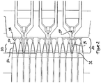
- Figure 2 illustrates a close up cross-sectional view of a portion of the injection mould press 10 with the mould tool 20 in a closed position.
- Figure 2 illustrates where the heated barrel 16 terminates in a nozzle 26 inside the mould tool 20.
- Mould tool 20 comprises a channel 28, a main body 30 and an overflow area 38.
- Molten plastics material 18 leaves the heated barrel 16 via nozzle 26 and is injected into the mould tool 20 through channel 28. Once channel 28 is filled with molten plastics material 18 the molten plastics material 18 continues to be forced into the main body 30 of the mould tool 20.
- the mould tool 20 is for forming a PCR plate.
- a typical PCR plate comprises a deck portion and a plurality of wells
- the PCR plate may optionally comprise a skirt portion which may be a full skirt or a semi or half skirt if present.
- the deck portion and the skirt portion if present are of much greater thickness of plastics material than the plurality of wells.
- the mould tool therefore needs to have portions for creating the thicker deck portion and skirt portion if present and portions for creating the thinner wells.
- the molten plastics material 18 is first forced into the thicker areas 32 of the main body 30 of the mould tool 20, which in the case of a PCR plate mould are the areas that form the deck portion.
- the molten plastics material 18 is then forced from the thicker areas 32 of the main body 30 of the mould tool 20 into the thinner areas 34 of the main body 30 of the mould tool 20, which in the case of a PCR plate mould are the areas that form the wells. In a traditional injection moulding process this is where the procedure would then stop and the finished plastics product would be ejected from the mould.
- the procedure continues such that once the thinner areas 34 of the main body 30 of the mould tool 20 are filled with molten plastics material 18, the molten plastics material 18 is then forced from the thinner areas 34 of the main body 30 of the mould tool 20 through an exit point 36, which in the case of a PCR plate mould is the point that form the bottoms of the wells, into overflow area 38.
- Overflow area 38 and channel 28 are configured to produce scrap products of similar thickness to each other such the complete flow of molten plastics material is from a substantially thick area being channel 28, to a thinner area 32 which in the case of a PCR plate would form the deck, to a substantially thinner area 34 which in the case of a PCR plate would form the wells, finally to a further substantially thick area being overflow area 38.
- the mould tool 20 comprising a final substantially thick area being overflow area 38 allows for any air trapped in the molten plastics material to be forced into this final area rather than remaining in the moulding of the plastics product, in addition the plastic flow pattern is improved flowing from thick to thin areas as there is this final thick area after the very thin area.
- Figure 3 illustrates a cross-sectional view of a portion of the mould tool 20 in an open position.
- the mould tool 20 comprises three physical portions 20a, 20b and 20c which when connected together create void spaces which comprise channel 28, main body 30 and overflow area 38.
- the mould tool 20 comprises three physical portions 20a, 20b and 20c, in an alternate embodiment may comprise less than or more than three physical portions, depending on the complexity of the mould tool 20 and the product to be moulded.
- the plastics product being moulded 40 is configured to eject from one side of the mould tool 20 between physical portions 20a and 20b of the mould tool 20, whilst the scrap products 42, 44 being the mouldings from the channel 28 and overflow area 38 respectively are configured to eject from the other side of the mould tool 20 between physical portions 20b and 20c of the mould tool.
- This enables ejected mouldings to be sorted into keeping and scrapping bins without additional user input.
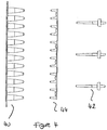
- FIGs 4 and 5 illustrate examples of the moulded plastics product 40 and the scrap products 42, 44 being the mouldings from the channel 28 and overflow area 38 respectively.
Landscapes
- Engineering & Computer Science (AREA)
- Manufacturing & Machinery (AREA)
- Mechanical Engineering (AREA)
- Health & Medical Sciences (AREA)
- Chemical & Material Sciences (AREA)
- General Health & Medical Sciences (AREA)
- Analytical Chemistry (AREA)
- Hematology (AREA)
- Clinical Laboratory Science (AREA)
- Chemical Kinetics & Catalysis (AREA)
- Injection Moulding Of Plastics Or The Like (AREA)
- Moulds For Moulding Plastics Or The Like (AREA)
- Casting Or Compression Moulding Of Plastics Or The Like (AREA)
- Sewage (AREA)
Description
- This invention relates to a moulding tool and method for forming a polypropylene PCR plate comprising a channel, a main body and an overflow area; wherein the channel is configured to facilitate the introduction of molten plastics material into the main body and wherein the main body is configured to facilitate the flow of the said molten plastics into the overflow area once the main body of the moulding tool has been filled with the said molten plastics.
- Current injection moulding apparatus and methods involve molten plastics material being injected into a mould (also called a mould tool or simply tool) from one or more nozzles through one or more channels in the mould called runners. The molten plastics material flows through the one or more runners into the main body of the mould. Once the entire volume of the mould is filled the one or more nozzles will cease injecting the molten plastics material into the one or more runners and thus into the main body of the mould and the mould will usually at that stage be opened (either automatically or manually) to eject the moulded part from the main body of the mould and the mouldings from the one or more runners from the mould.
- The problem with using this method and moulding apparatus for the mouldings of plastics materials for use in products which have sections of varying thickness, such as PCR plates, is that air can become trapped in the plastics material, flow is not always consistent from thicker areas of plastics material to thinner areas of plastics material and the finished moulded plastics material products are not always flat, which can lead to a substantial scrappaged of finished moulded plastics material products.
-
GB2453432 -
CN103991165 provides an injection moulding method of a PCR plate. The injection moulding method of the PCR plate comprises the following steps: A, preparing a PCR plate frame; B, forming a PCR plate cavity in a moulding die, enabling the PCR plate cavity to form a PCR plate frame cavity, a connection plate cavity and a plurality of reaction tube cavities, and putting the prepared PCR plate frame into the PCR plate frame cavity; C, injecting molten plastic raw material into the PCR plate cavity through the connection plate cavity to form the PCR plate, wherein a water opening of the prepared PCR plate is formed in the inner side of a connection plate; water openings are formed in reaction tubes. The reaction tubes are smooth and neat in surface, stable in size, excellent in light transmission effect and the reaction conditions of samples in the reaction tubes can be well observed and thus the detection effect of the product is improved; meanwhile, the die has few plastic inlets, so that the structure of the die is simplified, providing a high production efficiency; the product has few water openings, so that the production cost is low, and raw material is saved. -
JP2007245595 - According to a first aspect of the invention there is provided a mould tool configured to form a polypropylene PCR plate comprising a channel, a main body and an overflow area. The channel is configured to facilitate the introduction of molten polypropylene plastics material into the main body, and the main body is configured to facilitate the flow of the said molten polypropylene plastics into the overflow area once the main body of the mould tool has been filled with the said molten polypropylene plastics. The main body is open only to the channel and the overflow area, wherein the overflow area is only open to the main body such that the only entrance/exit to the mould tool is via the channel, wherein the main body of the mould tool comprises portions configured to create thick areas and thin areas in the said polypropylene PCR plate. The main body is configured to facilitate the flow of the said molten polypropylene plastics material from the portions configured to create thin areas in the said polypropylene PCR plate through an exit point that would form the bottom of wells of said polypropylene PCR plate into the overflow area.
- This is advantageous since the flow pattern from thick to thin areas is improved and any air that may be trapped in the molten plastics material is forced into the overflow area rather than remaining in the main body of the mould. This results in the finished moulded plastic product being flatter and without air bubbles, which in turn results in a reduction in plastic product that needs to be scrapped. The main body of the mould tool comprises portions configured to create thick areas and thin areas in the said polypropylene PCR plate.
- Preferably the mould tool is configured for standard injection moulding techniques. This is advantageous as the mould can be simply used in standard injection moulding appliances without the need for additional specialised equipment.
- Preferably the channel is configured to facilitate the introduction of only molten polypropylene plastics material into the main body of the mould tool.
- Preferably the thick areas are in the range of 0.90mm to 1 .50mm.
- Preferably the thin areas are in the range of 0.15mm to 0.30mm.
- Preferably the channel is configured to facilitate the introduction of molten polypropylene plastics material into the portions configured to create thick areas in the said polypropylene PCR plate of the main body.
- Preferably the main body is configured to facilitate the flow of the said molten polypropylene plastics material from the portions configured to create thick areas in the said polypropylene PCR plate into the portions configured to create thin areas in the said polypropylene PCR plate.
- Preferably the main body is configured to facilitate the flow of the said molten polypropylene plastics material from the portions configured to create thin areas in the said polypropylene PCR plate into the overflow area.
- Preferably the overflow area is configured to create a scrap product.
- Preferably the channel is configured to create a scrap product.
- Preferably the main body is configured to create the said plastics product.
- Preferably the overflow area is configured to create a scrap product which is of greater thickness than the portions of the main body configured to create thin areas in the said polypropylene PCR plate.
- Preferably the mould tool is configured to form a 24 well PCR plate.
- Preferably the mould tool is configured to form a 32 well PCR plate.
- Preferably the mould tool is configured to form a 48 well PCR plate.
- Preferably the mould tool is configured to form a 96 well PCR plate.
- Preferably the mould tool is configured to form a 384 well PCR plate.
- Preferably the portions of the main body that are configured to create thick areas in the said plastics product are configured to create the deck of the said PCR plate.
- Preferably the portions of the main body that are configured to create thick areas in the said plastics product are configured to create the deck and skirt of the said PCR plate.
- Preferably the portions of the main body that are configured to create thin areas in the said plastics product are configured to create the wells of the said PCR plate.
- Preferably the main body is configured to facilitate the flow of the said molten polypropylene plastics material from the portions configured to create the bottoms of the wells in the said PCR plate into the overflow area.
- According to a second aspect of the present invention there is provided a method of injection moulding a polypropylene PCR plate comprising the steps of
- a) providing a mould tool as described in relation to the first aspect of the invention;
- b) introducing molten polypropylene plastics material into the main body of the mould tool through the channel, such that once the main body of the mould tool is filled, the molten polypropylene plastics material is configured to fill the overflow area;
- c) ejecting the polypropylene PCR plate from the mould along with the moulding of the channel and the overflow area;
- d) discarding the moulding of the channel and the overflow area.
- Preferably the injection moulding is standard injection moulding. This is advantageous as the method can be simply used in standard injection moulding appliances without the need for additional specialised equipment.
- Preferably only molten polypropylene plastics material is introduced into the mould tool during the moulding process.
- Preferably the mould is not put under external pressure.
- Other aspects and features of the present invention will become apparent to those ordinarily skilled in the art upon review of the following description of specific embodiments of the invention in conjunction with the accompanying figures.
-
Figure 1 illustrates a typical injection mould press; -
Figure 2 illustrates a close up cross-sectional view of a portion of the mould tool in a closed position; -
Figure 3 illustrates a cross-sectional view of a portion of the mould tool in an open position; -
Figures 4 illustrates plan views of examples of the moulded plastics product and the scrap products; and -
Figures 5 illustrates perspective views of examples of the moulded plastics product and the scrap products. -
Figure1 illustrates a typicalinjection moulding assembly 10, which is known as aninjection mould press 10. Themould tool 20 is mounted in such aninjection mould press 10.Solid plastics material 14 is held in ahopper 12, and fed into a heatedbarrel 16 and mixed to form amolten plastics material 18 before being forced into themould tool 20. The solid/molten plastics material heated barrel 16 typically using arotating screw thread 24. Themolten plastics material 18 is typically forced into themould tool 20 by apressing ram 22 which may be hydraulically operated. The injection mould press may comprises more than onehopper 12, if different plastics materials need to be fed into themould tool 20, either together or sequentially. Theinjection mould press 10 may have one or moreheated barrels 16 or into the alternative theheated barrel 16 may split into a plurality of heated barrels. -
Figure 2 illustrates a close up cross-sectional view of a portion of theinjection mould press 10 with themould tool 20 in a closed position.Figure 2 illustrates where theheated barrel 16 terminates in anozzle 26 inside themould tool 20.Mould tool 20 comprises achannel 28, amain body 30 and anoverflow area 38.Molten plastics material 18 leaves theheated barrel 16 vianozzle 26 and is injected into themould tool 20 throughchannel 28. Oncechannel 28 is filled withmolten plastics material 18 themolten plastics material 18 continues to be forced into themain body 30 of themould tool 20. In the embodiment illustrated themould tool 20 is for forming a PCR plate. A typical PCR plate comprises a deck portion and a plurality of wells, the PCR plate may optionally comprise a skirt portion which may be a full skirt or a semi or half skirt if present. The deck portion and the skirt portion if present are of much greater thickness of plastics material than the plurality of wells. The mould tool therefore needs to have portions for creating the thicker deck portion and skirt portion if present and portions for creating the thinner wells. Typically once themolten plastics material 18 has been injected intochannel 28 themolten plastics material 18 is first forced into thethicker areas 32 of themain body 30 of themould tool 20, which in the case of a PCR plate mould are the areas that form the deck portion. Once thethicker areas 32 of themain body 30 of themould tool 20 are filled withmolten plastics material 18, themolten plastics material 18 is then forced from thethicker areas 32 of themain body 30 of themould tool 20 into thethinner areas 34 of themain body 30 of themould tool 20, which in the case of a PCR plate mould are the areas that form the wells. In a traditional injection moulding process this is where the procedure would then stop and the finished plastics product would be ejected from the mould. However, in the case of the present invention the procedure continues such that once thethinner areas 34 of themain body 30 of themould tool 20 are filled withmolten plastics material 18, themolten plastics material 18 is then forced from thethinner areas 34 of themain body 30 of themould tool 20 through anexit point 36, which in the case of a PCR plate mould is the point that form the bottoms of the wells, intooverflow area 38.Overflow area 38 andchannel 28 are configured to produce scrap products of similar thickness to each other such the complete flow of molten plastics material is from a substantially thickarea being channel 28, to athinner area 32 which in the case of a PCR plate would form the deck, to a substantiallythinner area 34 which in the case of a PCR plate would form the wells, finally to a further substantially thick area beingoverflow area 38. Themould tool 20 comprising a final substantially thick area beingoverflow area 38 allows for any air trapped in the molten plastics material to be forced into this final area rather than remaining in the moulding of the plastics product, in addition the plastic flow pattern is improved flowing from thick to thin areas as there is this final thick area after the very thin area. -
Figure 3 illustrates a cross-sectional view of a portion of themould tool 20 in an open position. As can be seen inFigure 3 themould tool 20 comprises threephysical portions channel 28,main body 30 andoverflow area 38. Whilst in the embodiment illustrated themould tool 20 comprises threephysical portions mould tool 20 and the product to be moulded. In the embodiment illustrated for ease of processing, the plastics product being moulded 40 is configured to eject from one side of themould tool 20 betweenphysical portions mould tool 20, whilst thescrap products channel 28 andoverflow area 38 respectively are configured to eject from the other side of themould tool 20 betweenphysical portions -
Figures 4 and5 illustrate examples of the mouldedplastics product 40 and thescrap products channel 28 andoverflow area 38 respectively.
Claims (15)
- A mould tool (20) configured to form a polypropylene PCR plate (40) comprising a channel (28), a main body (30) and an overflow area (38);
wherein the channel (28) is configured to facilitate the introduction of molten polypropylene plastics material into the main body (30) and wherein the main body (30) is configured to facilitate the flow of the said molten polypropylene plastics into the overflow area (38) once the main body (30) of the mould tool has been filled with the said molten polypropylene plastics;
wherein the main body (30) is open only to the channel {28) and the overflow area (38), wherein the overflow area (38) is only open to the main body (30) such that the only entrance/exit to the mould tool is via the channel (28), wherein the main body (30) of the mould tool comprises portions configured to create thick areas (32) and thin areas (34) in the said polypropylene PCR plate (40); and
wherein the main body (30) is configured to facilitate the flow of the said molten polypropylene plastics material from the portions configured to create thin areas (34) in the said polypropylene PCR plate (40) through an exit point (36) that would form the bottom of wells of said polypropylene PCR plate (40) into the overflow area (38). - A mould tool (20) as claimed in Claim 1 wherein the channel (28) is configured to facilitate the introduction of only molten polypropylene plastics material into the main body (30) of the mould tool.
- A mould tool (20) as claimed in any preceding claim wherein the thick areas (32) are in the range of 0.90mm to 1.50mm.
- A mould tool (20) as claimed in any preceding claim wherein the thin areas (34) are in the range of 0.15mm to 0.30mm.
- A mould tool (20) as claimed in any preceding claim wherein the channel (28) is configured to facilitate the introduction of molten polypropylene plastics material into the portions configured to create thick areas (32) in the said polypropylene PCR plate (40) of the main body (30).
- A mould tool (20) as claimed in any preceding claim wherein the main body (30) is configured to facilitate the flow of the said molten polypropylene plastics material from the portions configured to create thick areas (32) in the said polypropylene PCR plate (40) into the portions configured to create thin areas (34) in the said polypropylene PCR plate (40).
- A mould tool (20) as claimed in any preceding claim wherein the overflow area (38) is configured to create a scrap product (44), optionally wherein the overflow area (38) is configured to create a scrap product (44) which is of greater thickness than the portions of the main body configured to create thin areas (34) in the said polypropylene PCR plate (40); and/or
wherein the channel (28) is configured to create a scrap product (42). - A mould tool (20) as claimed in any preceding claim wherein the main body (30) is configured to create the said polypropylene PCR plate (40).
- A mould tool (20) as claimed in any preceding claim wherein the mould tool (20) is configured to form a 24 well PCR plate, a 32 well PCR plate, a 48 well PCR plate, a 96 well PCR plate, or a 384 well PCR plate.
- A mould tool (20) as claimed in any preceding claim wherein the portions of the main body that are configured to create thick areas (32) in the said polypropylene PCR plate are configured to create the deck or deck and skirt of the said PCR plate; and/or
wherein the portions of the main body that are configured to create thin areas (34) in the said plastics product are configured to create the wells of the said PCR plate. - A mould tool (20) as claimed in any preceding claim wherein the main body (30) is configured to facilitate the flow of the said molten plastics material from the portions configured to create the bottoms of the wells in the said PCR plate into the overflow area (38).
- A method of injection moulding a polypropylene PCR plate (40) comprising the steps ofa) providing a mould tool (20) as claimed in any of claims 1 to 11;b) introducing molten polypropylene plastics material into the main body (30) of the mould tool through the channel (28), such that once the main body (30) of the mould tool is filled, the molten polypropylene plastics material is configured to fill the overflow area (36);c) ejecting the polypropylene PCR plate (40) from the mould along with the moulding of the channel and the overflow area (42, 44);d) discarding the moulding of the channel and the overflow area (42, 44).
- A method as claimed in Claim 12 wherein only molten polypropylene plastics material is introduced into the mould tool during the moulding process.
- A method as claimed in Claim 12 or claim 13 wherein the mould is not put under external pressure.
- A method as claimed in any of Claims 12 to 14, wherein the injection moulding is standard injection moulding.
Applications Claiming Priority (2)
| Application Number | Priority Date | Filing Date | Title |
|---|---|---|---|
| GB1705760.5A GB2561356B (en) | 2017-04-10 | 2017-04-10 | Overflow moulding apparatus and method |
| PCT/GB2018/050264 WO2018189504A1 (en) | 2017-04-10 | 2018-01-30 | Moulding method and apparatus |
Publications (2)
| Publication Number | Publication Date |
|---|---|
| EP3609671A1 EP3609671A1 (en) | 2020-02-19 |
| EP3609671B1 true EP3609671B1 (en) | 2021-08-25 |
Family
ID=58744578
Family Applications (1)
| Application Number | Title | Priority Date | Filing Date |
|---|---|---|---|
| EP18704290.8A Active EP3609671B1 (en) | 2017-04-10 | 2018-01-30 | Moulding method and apparatus |
Country Status (6)
| Country | Link |
|---|---|
| US (1) | US20200122372A1 (en) |
| EP (1) | EP3609671B1 (en) |
| CN (1) | CN110520268B (en) |
| GB (1) | GB2561356B (en) |
| MX (1) | MX393933B (en) |
| WO (1) | WO2018189504A1 (en) |
Family Cites Families (10)
| Publication number | Priority date | Publication date | Assignee | Title |
|---|---|---|---|---|
| DE10212761B4 (en) * | 2002-03-22 | 2009-12-31 | Eppendorf Ag | microtiter plate |
| DE102004006074A1 (en) * | 2004-02-07 | 2005-08-25 | Hennecke Gmbh | Process and device for the production of polyurethane molded parts |
| JP4845180B2 (en) * | 2005-08-25 | 2011-12-28 | 森六テクノロジー株式会社 | Injection mold apparatus and injection molding method |
| JP5060060B2 (en) * | 2006-03-17 | 2012-10-31 | 日立マクセル株式会社 | Mold and molding method using mold |
| GB0719193D0 (en) * | 2007-10-02 | 2007-11-07 | Advanced Biotech Ltd | A Vessel |
| JP2013520643A (en) * | 2010-02-22 | 2013-06-06 | フォーティテュード リミテッド | Multiwell strip |
| CN103038036B (en) * | 2010-08-09 | 2015-07-08 | 斯恩蒂斯有限公司 | Method for manufacturing injection molded products |
| CN203973929U (en) * | 2014-06-09 | 2014-12-03 | 钟灿秋 | PCR plate injection molding mold |
| CN103991165B (en) * | 2014-06-09 | 2016-08-24 | 东莞市积健生物科技有限公司 | A kind of PCR plate injection molding forming method |
| CN104015306B (en) * | 2014-06-09 | 2016-08-31 | 东莞市积健生物科技有限公司 | PCR plate injection forming mold and method thereof |
-
2017
- 2017-04-10 GB GB1705760.5A patent/GB2561356B/en active Active
-
2018
- 2018-01-30 EP EP18704290.8A patent/EP3609671B1/en active Active
- 2018-01-30 CN CN201880021512.2A patent/CN110520268B/en active Active
- 2018-01-30 WO PCT/GB2018/050264 patent/WO2018189504A1/en not_active Ceased
- 2018-01-30 MX MX2019012121A patent/MX393933B/en unknown
- 2018-01-30 US US16/604,503 patent/US20200122372A1/en not_active Abandoned
Non-Patent Citations (1)
| Title |
|---|
| None * |
Also Published As
| Publication number | Publication date |
|---|---|
| MX393933B (en) | 2025-03-24 |
| MX2019012121A (en) | 2019-11-21 |
| CN110520268B (en) | 2022-04-12 |
| GB201705760D0 (en) | 2017-05-24 |
| GB2561356B (en) | 2021-02-24 |
| CN110520268A (en) | 2019-11-29 |
| WO2018189504A1 (en) | 2018-10-18 |
| GB2561356A (en) | 2018-10-17 |
| US20200122372A1 (en) | 2020-04-23 |
| EP3609671A1 (en) | 2020-02-19 |
Similar Documents
| Publication | Publication Date | Title |
|---|---|---|
| US20090117648A1 (en) | Vessel and method of manufacture thereof | |
| WO2009044196A1 (en) | A pcr vessel with thin lower walls | |
| KR101825995B1 (en) | Integral molding manufacturing method and manufacturing device for waterproof structure of 3c electronic products | |
| KR101199744B1 (en) | Extrusion die for synthetic wood, apparatus and manufacturing method containing the same and the synthetic wood of the same | |
| CN1557619A (en) | Method and device for long fibre filling reinforced plastic injection moulding | |
| CN103747936B (en) | A kind of stripper sleeve | |
| US7108823B2 (en) | Staged compression molding process | |
| CN108407223A (en) | A kind of preceding mould ejecting structure injection mold | |
| US20200122372A1 (en) | Moulding method and apparatus | |
| CN105538485B (en) | A kind of ceramic part injecting molding die and its injection moulding method | |
| CN105835282A (en) | Die pressing device for producing large-size wood-plastic composite board | |
| CN107415175B (en) | Cutting device in injection mold glue feeding mold | |
| CN210820652U (en) | Multi-channel injection mold | |
| CN103990803A (en) | Tungsten-molybdenum alloy powder injection technology and mould thereof | |
| CN219311871U (en) | Mold core structure and injection molding system with same | |
| CN106003539B (en) | A kind of BMC injection molding technique | |
| CN217318960U (en) | Quick color-changing hot runner structure | |
| KR20140104781A (en) | Dual Chamber Tube Vessel Assembly with Cap and the Method of Making It | |
| CN213107901U (en) | Injection mold of vehicle-mounted backlight module | |
| CN222135760U (en) | Centrifuging tube mould for injection moulding convenient to drawing of patterns | |
| CN217531765U (en) | Recompression device in mould | |
| CN218557812U (en) | Lower cover die with multistage stretching structure for edible oil bottle cap | |
| CN213919374U (en) | Be applied to injection mold of outdoor table of high anti-impact height resistant light oxygen ageing | |
| CN218315098U (en) | Extrusion die for large and wide plastic foam board | |
| CN214926779U (en) | Material taking equipment for injection mold |
Legal Events
| Date | Code | Title | Description |
|---|---|---|---|
| STAA | Information on the status of an ep patent application or granted ep patent |
Free format text: STATUS: UNKNOWN |
|
| STAA | Information on the status of an ep patent application or granted ep patent |
Free format text: STATUS: THE INTERNATIONAL PUBLICATION HAS BEEN MADE |
|
| PUAI | Public reference made under article 153(3) epc to a published international application that has entered the european phase |
Free format text: ORIGINAL CODE: 0009012 |
|
| STAA | Information on the status of an ep patent application or granted ep patent |
Free format text: STATUS: REQUEST FOR EXAMINATION WAS MADE |
|
| 17P | Request for examination filed |
Effective date: 20191029 |
|
| AK | Designated contracting states |
Kind code of ref document: A1 Designated state(s): AL AT BE BG CH CY CZ DE DK EE ES FI FR GB GR HR HU IE IS IT LI LT LU LV MC MK MT NL NO PL PT RO RS SE SI SK SM TR |
|
| AX | Request for extension of the european patent |
Extension state: BA ME |
|
| DAV | Request for validation of the european patent (deleted) | ||
| DAX | Request for extension of the european patent (deleted) | ||
| RIC1 | Information provided on ipc code assigned before grant |
Ipc: B29C 45/26 20060101AFI20200930BHEP Ipc: B29L 7/00 20060101ALN20200930BHEP Ipc: B29K 23/00 20060101ALI20200930BHEP Ipc: B29C 33/00 20060101ALI20200930BHEP Ipc: B29L 31/00 20060101ALN20200930BHEP Ipc: B01L 3/00 20060101ALN20200930BHEP |
|
| RIC1 | Information provided on ipc code assigned before grant |
Ipc: B29L 31/00 20060101ALN20201013BHEP Ipc: B29C 45/26 20060101AFI20201013BHEP Ipc: B29L 7/00 20060101ALN20201013BHEP Ipc: B29C 33/00 20060101ALI20201013BHEP Ipc: B29K 23/00 20060101ALI20201013BHEP Ipc: B01L 3/00 20060101ALN20201013BHEP |
|
| GRAP | Despatch of communication of intention to grant a patent |
Free format text: ORIGINAL CODE: EPIDOSNIGR1 |
|
| STAA | Information on the status of an ep patent application or granted ep patent |
Free format text: STATUS: GRANT OF PATENT IS INTENDED |
|
| RIC1 | Information provided on ipc code assigned before grant |
Ipc: B29C 45/26 20060101AFI20201030BHEP Ipc: B29C 33/00 20060101ALI20201030BHEP Ipc: B29K 23/00 20060101ALI20201030BHEP Ipc: B29L 7/00 20060101ALN20201030BHEP Ipc: B01L 3/00 20060101ALN20201030BHEP Ipc: B29L 31/00 20060101ALN20201030BHEP |
|
| INTG | Intention to grant announced |
Effective date: 20201123 |
|
| GRAJ | Information related to disapproval of communication of intention to grant by the applicant or resumption of examination proceedings by the epo deleted |
Free format text: ORIGINAL CODE: EPIDOSDIGR1 |
|
| STAA | Information on the status of an ep patent application or granted ep patent |
Free format text: STATUS: REQUEST FOR EXAMINATION WAS MADE |
|
| INTC | Intention to grant announced (deleted) | ||
| RIC1 | Information provided on ipc code assigned before grant |
Ipc: B29L 31/00 20060101ALN20210322BHEP Ipc: B29L 7/00 20060101ALN20210322BHEP Ipc: B01L 3/00 20060101ALN20210322BHEP Ipc: B29K 23/00 20060101ALI20210322BHEP Ipc: B29C 33/00 20060101ALI20210322BHEP Ipc: B29C 45/26 20060101AFI20210322BHEP |
|
| GRAP | Despatch of communication of intention to grant a patent |
Free format text: ORIGINAL CODE: EPIDOSNIGR1 |
|
| STAA | Information on the status of an ep patent application or granted ep patent |
Free format text: STATUS: GRANT OF PATENT IS INTENDED |
|
| RIC1 | Information provided on ipc code assigned before grant |
Ipc: B29L 31/00 20060101ALN20210330BHEP Ipc: B29L 7/00 20060101ALN20210330BHEP Ipc: B01L 3/00 20060101ALN20210330BHEP Ipc: B29K 23/00 20060101ALI20210330BHEP Ipc: B29C 33/00 20060101ALI20210330BHEP Ipc: B29C 45/26 20060101AFI20210330BHEP |
|
| RIC1 | Information provided on ipc code assigned before grant |
Ipc: B29L 31/00 20060101ALN20210415BHEP Ipc: B29L 7/00 20060101ALN20210415BHEP Ipc: B01L 3/00 20060101ALN20210415BHEP Ipc: B29K 23/00 20060101ALI20210415BHEP Ipc: B29C 33/00 20060101ALI20210415BHEP Ipc: B29C 45/26 20060101AFI20210415BHEP |
|
| RIC1 | Information provided on ipc code assigned before grant |
Ipc: B29L 31/00 20060101ALN20210420BHEP Ipc: B29L 7/00 20060101ALN20210420BHEP Ipc: B01L 3/00 20060101ALN20210420BHEP Ipc: B29K 23/00 20060101ALI20210420BHEP Ipc: B29C 33/00 20060101ALI20210420BHEP Ipc: B29C 45/26 20060101AFI20210420BHEP |
|
| INTG | Intention to grant announced |
Effective date: 20210504 |
|
| GRAS | Grant fee paid |
Free format text: ORIGINAL CODE: EPIDOSNIGR3 |
|
| GRAA | (expected) grant |
Free format text: ORIGINAL CODE: 0009210 |
|
| STAA | Information on the status of an ep patent application or granted ep patent |
Free format text: STATUS: THE PATENT HAS BEEN GRANTED |
|
| AK | Designated contracting states |
Kind code of ref document: B1 Designated state(s): AL AT BE BG CH CY CZ DE DK EE ES FI FR GB GR HR HU IE IS IT LI LT LU LV MC MK MT NL NO PL PT RO RS SE SI SK SM TR |
|
| REG | Reference to a national code |
Ref country code: CH Ref legal event code: EP |
|
| REG | Reference to a national code |
Ref country code: DE Ref legal event code: R096 Ref document number: 602018022350 Country of ref document: DE |
|
| REG | Reference to a national code |
Ref country code: IE Ref legal event code: FG4D Ref country code: AT Ref legal event code: REF Ref document number: 1423333 Country of ref document: AT Kind code of ref document: T Effective date: 20210915 |
|
| REG | Reference to a national code |
Ref country code: LT Ref legal event code: MG9D |
|
| REG | Reference to a national code |
Ref country code: NL Ref legal event code: MP Effective date: 20210825 |
|
| REG | Reference to a national code |
Ref country code: AT Ref legal event code: MK05 Ref document number: 1423333 Country of ref document: AT Kind code of ref document: T Effective date: 20210825 |
|
| PG25 | Lapsed in a contracting state [announced via postgrant information from national office to epo] |
Ref country code: AT Free format text: LAPSE BECAUSE OF FAILURE TO SUBMIT A TRANSLATION OF THE DESCRIPTION OR TO PAY THE FEE WITHIN THE PRESCRIBED TIME-LIMIT Effective date: 20210825 Ref country code: BG Free format text: LAPSE BECAUSE OF FAILURE TO SUBMIT A TRANSLATION OF THE DESCRIPTION OR TO PAY THE FEE WITHIN THE PRESCRIBED TIME-LIMIT Effective date: 20211125 Ref country code: LT Free format text: LAPSE BECAUSE OF FAILURE TO SUBMIT A TRANSLATION OF THE DESCRIPTION OR TO PAY THE FEE WITHIN THE PRESCRIBED TIME-LIMIT Effective date: 20210825 Ref country code: NO Free format text: LAPSE BECAUSE OF FAILURE TO SUBMIT A TRANSLATION OF THE DESCRIPTION OR TO PAY THE FEE WITHIN THE PRESCRIBED TIME-LIMIT Effective date: 20211125 Ref country code: PT Free format text: LAPSE BECAUSE OF FAILURE TO SUBMIT A TRANSLATION OF THE DESCRIPTION OR TO PAY THE FEE WITHIN THE PRESCRIBED TIME-LIMIT Effective date: 20211227 Ref country code: RS Free format text: LAPSE BECAUSE OF FAILURE TO SUBMIT A TRANSLATION OF THE DESCRIPTION OR TO PAY THE FEE WITHIN THE PRESCRIBED TIME-LIMIT Effective date: 20210825 Ref country code: SE Free format text: LAPSE BECAUSE OF FAILURE TO SUBMIT A TRANSLATION OF THE DESCRIPTION OR TO PAY THE FEE WITHIN THE PRESCRIBED TIME-LIMIT Effective date: 20210825 Ref country code: ES Free format text: LAPSE BECAUSE OF FAILURE TO SUBMIT A TRANSLATION OF THE DESCRIPTION OR TO PAY THE FEE WITHIN THE PRESCRIBED TIME-LIMIT Effective date: 20210825 Ref country code: FI Free format text: LAPSE BECAUSE OF FAILURE TO SUBMIT A TRANSLATION OF THE DESCRIPTION OR TO PAY THE FEE WITHIN THE PRESCRIBED TIME-LIMIT Effective date: 20210825 Ref country code: HR Free format text: LAPSE BECAUSE OF FAILURE TO SUBMIT A TRANSLATION OF THE DESCRIPTION OR TO PAY THE FEE WITHIN THE PRESCRIBED TIME-LIMIT Effective date: 20210825 |
|
| PG25 | Lapsed in a contracting state [announced via postgrant information from national office to epo] |
Ref country code: PL Free format text: LAPSE BECAUSE OF FAILURE TO SUBMIT A TRANSLATION OF THE DESCRIPTION OR TO PAY THE FEE WITHIN THE PRESCRIBED TIME-LIMIT Effective date: 20210825 Ref country code: LV Free format text: LAPSE BECAUSE OF FAILURE TO SUBMIT A TRANSLATION OF THE DESCRIPTION OR TO PAY THE FEE WITHIN THE PRESCRIBED TIME-LIMIT Effective date: 20210825 Ref country code: GR Free format text: LAPSE BECAUSE OF FAILURE TO SUBMIT A TRANSLATION OF THE DESCRIPTION OR TO PAY THE FEE WITHIN THE PRESCRIBED TIME-LIMIT Effective date: 20211126 |
|
| PG25 | Lapsed in a contracting state [announced via postgrant information from national office to epo] |
Ref country code: NL Free format text: LAPSE BECAUSE OF FAILURE TO SUBMIT A TRANSLATION OF THE DESCRIPTION OR TO PAY THE FEE WITHIN THE PRESCRIBED TIME-LIMIT Effective date: 20210825 |
|
| PG25 | Lapsed in a contracting state [announced via postgrant information from national office to epo] |
Ref country code: DK Free format text: LAPSE BECAUSE OF FAILURE TO SUBMIT A TRANSLATION OF THE DESCRIPTION OR TO PAY THE FEE WITHIN THE PRESCRIBED TIME-LIMIT Effective date: 20210825 |
|
| REG | Reference to a national code |
Ref country code: DE Ref legal event code: R097 Ref document number: 602018022350 Country of ref document: DE |
|
| PG25 | Lapsed in a contracting state [announced via postgrant information from national office to epo] |
Ref country code: SM Free format text: LAPSE BECAUSE OF FAILURE TO SUBMIT A TRANSLATION OF THE DESCRIPTION OR TO PAY THE FEE WITHIN THE PRESCRIBED TIME-LIMIT Effective date: 20210825 Ref country code: SK Free format text: LAPSE BECAUSE OF FAILURE TO SUBMIT A TRANSLATION OF THE DESCRIPTION OR TO PAY THE FEE WITHIN THE PRESCRIBED TIME-LIMIT Effective date: 20210825 Ref country code: RO Free format text: LAPSE BECAUSE OF FAILURE TO SUBMIT A TRANSLATION OF THE DESCRIPTION OR TO PAY THE FEE WITHIN THE PRESCRIBED TIME-LIMIT Effective date: 20210825 Ref country code: EE Free format text: LAPSE BECAUSE OF FAILURE TO SUBMIT A TRANSLATION OF THE DESCRIPTION OR TO PAY THE FEE WITHIN THE PRESCRIBED TIME-LIMIT Effective date: 20210825 Ref country code: CZ Free format text: LAPSE BECAUSE OF FAILURE TO SUBMIT A TRANSLATION OF THE DESCRIPTION OR TO PAY THE FEE WITHIN THE PRESCRIBED TIME-LIMIT Effective date: 20210825 Ref country code: AL Free format text: LAPSE BECAUSE OF FAILURE TO SUBMIT A TRANSLATION OF THE DESCRIPTION OR TO PAY THE FEE WITHIN THE PRESCRIBED TIME-LIMIT Effective date: 20210825 |
|
| PLBE | No opposition filed within time limit |
Free format text: ORIGINAL CODE: 0009261 |
|
| STAA | Information on the status of an ep patent application or granted ep patent |
Free format text: STATUS: NO OPPOSITION FILED WITHIN TIME LIMIT |
|
| PG25 | Lapsed in a contracting state [announced via postgrant information from national office to epo] |
Ref country code: IT Free format text: LAPSE BECAUSE OF FAILURE TO SUBMIT A TRANSLATION OF THE DESCRIPTION OR TO PAY THE FEE WITHIN THE PRESCRIBED TIME-LIMIT Effective date: 20210825 |
|
| 26N | No opposition filed |
Effective date: 20220527 |
|
| PG25 | Lapsed in a contracting state [announced via postgrant information from national office to epo] |
Ref country code: SI Free format text: LAPSE BECAUSE OF FAILURE TO SUBMIT A TRANSLATION OF THE DESCRIPTION OR TO PAY THE FEE WITHIN THE PRESCRIBED TIME-LIMIT Effective date: 20210825 Ref country code: MC Free format text: LAPSE BECAUSE OF FAILURE TO SUBMIT A TRANSLATION OF THE DESCRIPTION OR TO PAY THE FEE WITHIN THE PRESCRIBED TIME-LIMIT Effective date: 20210825 |
|
| REG | Reference to a national code |
Ref country code: CH Ref legal event code: PL |
|
| REG | Reference to a national code |
Ref country code: BE Ref legal event code: MM Effective date: 20220131 |
|
| PG25 | Lapsed in a contracting state [announced via postgrant information from national office to epo] |
Ref country code: LU Free format text: LAPSE BECAUSE OF NON-PAYMENT OF DUE FEES Effective date: 20220130 |
|
| PG25 | Lapsed in a contracting state [announced via postgrant information from national office to epo] |
Ref country code: FR Free format text: LAPSE BECAUSE OF NON-PAYMENT OF DUE FEES Effective date: 20220131 Ref country code: BE Free format text: LAPSE BECAUSE OF NON-PAYMENT OF DUE FEES Effective date: 20220131 |
|
| PG25 | Lapsed in a contracting state [announced via postgrant information from national office to epo] |
Ref country code: LI Free format text: LAPSE BECAUSE OF NON-PAYMENT OF DUE FEES Effective date: 20220131 Ref country code: CH Free format text: LAPSE BECAUSE OF NON-PAYMENT OF DUE FEES Effective date: 20220131 |
|
| PG25 | Lapsed in a contracting state [announced via postgrant information from national office to epo] |
Ref country code: IE Free format text: LAPSE BECAUSE OF NON-PAYMENT OF DUE FEES Effective date: 20220130 |
|
| PG25 | Lapsed in a contracting state [announced via postgrant information from national office to epo] |
Ref country code: MK Free format text: LAPSE BECAUSE OF FAILURE TO SUBMIT A TRANSLATION OF THE DESCRIPTION OR TO PAY THE FEE WITHIN THE PRESCRIBED TIME-LIMIT Effective date: 20210825 Ref country code: CY Free format text: LAPSE BECAUSE OF FAILURE TO SUBMIT A TRANSLATION OF THE DESCRIPTION OR TO PAY THE FEE WITHIN THE PRESCRIBED TIME-LIMIT Effective date: 20210825 |
|
| PG25 | Lapsed in a contracting state [announced via postgrant information from national office to epo] |
Ref country code: HU Free format text: LAPSE BECAUSE OF FAILURE TO SUBMIT A TRANSLATION OF THE DESCRIPTION OR TO PAY THE FEE WITHIN THE PRESCRIBED TIME-LIMIT; INVALID AB INITIO Effective date: 20180130 |
|
| PG25 | Lapsed in a contracting state [announced via postgrant information from national office to epo] |
Ref country code: MT Free format text: LAPSE BECAUSE OF FAILURE TO SUBMIT A TRANSLATION OF THE DESCRIPTION OR TO PAY THE FEE WITHIN THE PRESCRIBED TIME-LIMIT Effective date: 20210825 |
|
| PG25 | Lapsed in a contracting state [announced via postgrant information from national office to epo] |
Ref country code: TR Free format text: LAPSE BECAUSE OF FAILURE TO SUBMIT A TRANSLATION OF THE DESCRIPTION OR TO PAY THE FEE WITHIN THE PRESCRIBED TIME-LIMIT Effective date: 20210825 |
|
| PGFP | Annual fee paid to national office [announced via postgrant information from national office to epo] |
Ref country code: GB Payment date: 20260109 Year of fee payment: 9 |
|
| PGFP | Annual fee paid to national office [announced via postgrant information from national office to epo] |
Ref country code: DE Payment date: 20251211 Year of fee payment: 9 |