EP3609559B1 - Dispositif de type seringue à distribution contrôlée - Google Patents
Dispositif de type seringue à distribution contrôlée Download PDFInfo
- Publication number
- EP3609559B1 EP3609559B1 EP18720498.7A EP18720498A EP3609559B1 EP 3609559 B1 EP3609559 B1 EP 3609559B1 EP 18720498 A EP18720498 A EP 18720498A EP 3609559 B1 EP3609559 B1 EP 3609559B1
- Authority
- EP
- European Patent Office
- Prior art keywords
- plunger rod
- syringe barrel
- counter member
- plunger
- periodic features
- Prior art date
- Legal status (The legal status is an assumption and is not a legal conclusion. Google has not performed a legal analysis and makes no representation as to the accuracy of the status listed.)
- Active
Links
- 230000000737 periodic effect Effects 0.000 claims description 48
- 239000000463 material Substances 0.000 claims description 20
- 210000003811 finger Anatomy 0.000 claims description 13
- 238000000034 method Methods 0.000 claims description 8
- 210000003813 thumb Anatomy 0.000 claims description 6
- 238000009420 retrofitting Methods 0.000 claims description 4
- 239000008280 blood Substances 0.000 description 8
- 210000004369 blood Anatomy 0.000 description 8
- XEEYBQQBJWHFJM-UHFFFAOYSA-N Iron Chemical compound [Fe] XEEYBQQBJWHFJM-UHFFFAOYSA-N 0.000 description 6
- 238000000502 dialysis Methods 0.000 description 5
- 239000003814 drug Substances 0.000 description 4
- 229940079593 drug Drugs 0.000 description 4
- 239000012530 fluid Substances 0.000 description 4
- 230000008901 benefit Effects 0.000 description 3
- 238000002347 injection Methods 0.000 description 3
- 239000007924 injection Substances 0.000 description 3
- 229910052742 iron Inorganic materials 0.000 description 3
- 230000008859 change Effects 0.000 description 2
- 238000001631 haemodialysis Methods 0.000 description 2
- 230000000322 hemodialysis Effects 0.000 description 2
- 230000007246 mechanism Effects 0.000 description 2
- 238000012986 modification Methods 0.000 description 2
- 230000004048 modification Effects 0.000 description 2
- 230000001419 dependent effect Effects 0.000 description 1
- 238000006073 displacement reaction Methods 0.000 description 1
- 238000001914 filtration Methods 0.000 description 1
- 210000004247 hand Anatomy 0.000 description 1
- 229940025708 injectable product Drugs 0.000 description 1
- 238000002483 medication Methods 0.000 description 1
- 230000008569 process Effects 0.000 description 1
- 230000001681 protective effect Effects 0.000 description 1
- 238000005086 pumping Methods 0.000 description 1
- 230000003014 reinforcing effect Effects 0.000 description 1
- 229960005486 vaccine Drugs 0.000 description 1
Images


Classifications
-
- A—HUMAN NECESSITIES
- A61—MEDICAL OR VETERINARY SCIENCE; HYGIENE
- A61M—DEVICES FOR INTRODUCING MEDIA INTO, OR ONTO, THE BODY; DEVICES FOR TRANSDUCING BODY MEDIA OR FOR TAKING MEDIA FROM THE BODY; DEVICES FOR PRODUCING OR ENDING SLEEP OR STUPOR
- A61M5/00—Devices for bringing media into the body in a subcutaneous, intra-vascular or intramuscular way; Accessories therefor, e.g. filling or cleaning devices, arm-rests
- A61M5/178—Syringes
- A61M5/31—Details
- A61M5/315—Pistons; Piston-rods; Guiding, blocking or restricting the movement of the rod or piston; Appliances on the rod for facilitating dosing ; Dosing mechanisms
- A61M5/31501—Means for blocking or restricting the movement of the rod or piston
-
- A—HUMAN NECESSITIES
- A61—MEDICAL OR VETERINARY SCIENCE; HYGIENE
- A61M—DEVICES FOR INTRODUCING MEDIA INTO, OR ONTO, THE BODY; DEVICES FOR TRANSDUCING BODY MEDIA OR FOR TAKING MEDIA FROM THE BODY; DEVICES FOR PRODUCING OR ENDING SLEEP OR STUPOR
- A61M5/00—Devices for bringing media into the body in a subcutaneous, intra-vascular or intramuscular way; Accessories therefor, e.g. filling or cleaning devices, arm-rests
- A61M5/178—Syringes
- A61M5/31—Details
- A61M5/315—Pistons; Piston-rods; Guiding, blocking or restricting the movement of the rod or piston; Appliances on the rod for facilitating dosing ; Dosing mechanisms
- A61M5/31511—Piston or piston-rod constructions, e.g. connection of piston with piston-rod
-
- A—HUMAN NECESSITIES
- A61—MEDICAL OR VETERINARY SCIENCE; HYGIENE
- A61M—DEVICES FOR INTRODUCING MEDIA INTO, OR ONTO, THE BODY; DEVICES FOR TRANSDUCING BODY MEDIA OR FOR TAKING MEDIA FROM THE BODY; DEVICES FOR PRODUCING OR ENDING SLEEP OR STUPOR
- A61M5/00—Devices for bringing media into the body in a subcutaneous, intra-vascular or intramuscular way; Accessories therefor, e.g. filling or cleaning devices, arm-rests
- A61M5/178—Syringes
- A61M5/31—Details
- A61M5/315—Pistons; Piston-rods; Guiding, blocking or restricting the movement of the rod or piston; Appliances on the rod for facilitating dosing ; Dosing mechanisms
- A61M5/31565—Administration mechanisms, i.e. constructional features, modes of administering a dose
- A61M5/31566—Means improving security or handling thereof
- A61M5/31568—Means keeping track of the total dose administered, e.g. since the cartridge was inserted
-
- A—HUMAN NECESSITIES
- A61—MEDICAL OR VETERINARY SCIENCE; HYGIENE
- A61M—DEVICES FOR INTRODUCING MEDIA INTO, OR ONTO, THE BODY; DEVICES FOR TRANSDUCING BODY MEDIA OR FOR TAKING MEDIA FROM THE BODY; DEVICES FOR PRODUCING OR ENDING SLEEP OR STUPOR
- A61M5/00—Devices for bringing media into the body in a subcutaneous, intra-vascular or intramuscular way; Accessories therefor, e.g. filling or cleaning devices, arm-rests
- A61M5/178—Syringes
- A61M5/31—Details
- A61M5/315—Pistons; Piston-rods; Guiding, blocking or restricting the movement of the rod or piston; Appliances on the rod for facilitating dosing ; Dosing mechanisms
- A61M5/31565—Administration mechanisms, i.e. constructional features, modes of administering a dose
- A61M5/3159—Dose expelling manners
- A61M5/31593—Multi-dose, i.e. individually set dose repeatedly administered from the same medicament reservoir
- A61M5/31595—Pre-defined multi-dose administration by repeated overcoming of means blocking the free advancing movement of piston rod, e.g. by tearing or de-blocking
-
- A—HUMAN NECESSITIES
- A61—MEDICAL OR VETERINARY SCIENCE; HYGIENE
- A61M—DEVICES FOR INTRODUCING MEDIA INTO, OR ONTO, THE BODY; DEVICES FOR TRANSDUCING BODY MEDIA OR FOR TAKING MEDIA FROM THE BODY; DEVICES FOR PRODUCING OR ENDING SLEEP OR STUPOR
- A61M5/00—Devices for bringing media into the body in a subcutaneous, intra-vascular or intramuscular way; Accessories therefor, e.g. filling or cleaning devices, arm-rests
- A61M5/178—Syringes
- A61M5/31—Details
- A61M5/315—Pistons; Piston-rods; Guiding, blocking or restricting the movement of the rod or piston; Appliances on the rod for facilitating dosing ; Dosing mechanisms
- A61M5/31501—Means for blocking or restricting the movement of the rod or piston
- A61M2005/31508—Means for blocking or restricting the movement of the rod or piston provided on the piston-rod
-
- A—HUMAN NECESSITIES
- A61—MEDICAL OR VETERINARY SCIENCE; HYGIENE
- A61M—DEVICES FOR INTRODUCING MEDIA INTO, OR ONTO, THE BODY; DEVICES FOR TRANSDUCING BODY MEDIA OR FOR TAKING MEDIA FROM THE BODY; DEVICES FOR PRODUCING OR ENDING SLEEP OR STUPOR
- A61M2207/00—Methods of manufacture, assembly or production
Definitions
- the invention relates, in general, to a syringe for the controlled delivery of a metered dose of injectable product, and, more particularly, to a syringe including features to assist in the delivery of medications when direct observation of the syringe barrel is difficult, and even more particularly, to a syringe that includes a tactile feedback of dose progression and additional features that prevent catastrophic back-flow caused by line pressure during use with medical devices.
- Dose dividing delivery devices are known for dividing injectable material into multiple sub-doses for injection through a needle, such as for the delivery of drugs, vaccines, and the like.
- One such example is disclosed in U.S. Patent No. 8,939,959 .
- This dose dividing delivery device uses a ratcheting mechanism built into the plunger rod to enable multi-site injections.
- the device disclosed in the patent requires the medical practitioner to use two hands to operate the device as it includes the steps of stopping at each interval and actuating in a radial direction to enable administration of the next increment or dose.
- Certain medical devices are used for treatment of individuals that require the administration of a metered dose of injectable material.
- One such medical device is a dialysis machine.
- iron is administered to a patient to compensate for losses associated with blood filtration.
- the normal administration practice for iron medication comprises delivering the doses with several pushes of a syringe device while the dialysis treatment is undergoing.
- medical practitioners are required to inject the medication into an external blood loop of the hemodialysis machine.
- the orientation of the syringe and ergonomics of the operation are such that direct observation of the movement of the stopper inside the syringe barrel is hindered. This makes it difficult for the practitioner to regulate or monitor the amount of the fluid being injected.
- the practitioner has to estimate the amount of fluid being injected based on the movement of the plunger within the syringe.
- the injection is done in the external blood loop, which is under elevated pumping pressure from the dialysis machine. Consequently, if the syringe is left unattended while connected to the loop, the stopper can be pushed back out of the barrel by the pressure in the loop. This can result in blood being expelled out at a high rate.
- the medical practitioner clamps the "pigtail" tubing line, connecting the syringe to the blood loop, to isolate the syringe from the blood loop pressure. Since the iron is administered in multiple periodic pushes, there are several times when the clamp is actuated on the line. This requires a significant amount of care by the practitioner to prevent a catastrophic blow-back event.
- a syringe fitted with a mechanism that provides a tactile feedback to the practitioner informing of dose progression There is further a need in the art for the practitioner to monitor the volume of the fluid that is injected.
- a device that automatically locks and prevents the stopper from being pushed back and out of the syringe This type of device would provide an added layer of protection against a catastrophic failure resulting from clamp failure.
- a controlled delivery syringe device which is defined within the preamble of claim 1 is described in US 2014/0276588 A1 .
- a controlled delivery syringe device in accordance with an embodiment of the present invention, includes a syringe barrel having a proximal end and distal end which defines a chamber therein. The chamber is configured for containing an injectable material.
- a plunger rod is associated with the syringe barrel and a plunger is secured to the plunger rod and axially movable within the syringe barrel.
- a plurality of equally and sequentially spaced periodic features are associated with at least a portion of the plunger rod and a counter member is engageable with the periodic features.
- the plunger rod is configured so that the application of a distally directed force thereto results in disengagement and reengagement of the counter member with the sequentially spaced periodic features on the plunger rod, enabling advancement of the plunger rod and plunger in the syringe barrel while providing tactile feedback of dose progression of the injectable material. Reengagement of the counter member with the sequentially spaced periodic features prevents retraction of the plunger rod and plunger within the syringe barrel.
- the plunger rod comprises a thumb press located at a proximal end of the plunger rod to receive the application of the distally directed force to the plunger rod resulting in disengagement and reengagement of the counter member with the sequentially spaced periodic feature on the plunger rod.
- the periodic features can be angled such that upon disengagement of the counter member therefrom, the angled surface of the features can apply an outwardly directed force to the counter member, pushing the counter member out of the way so that the plunger rod can advance.
- a device including an actuating member comprising at least one tab having an engagement end and a finger press end and wherein application of a pivoting force to the at least one tab results in disengagement and reengagement of the counter member with a sequentially spaced periodic feature on the plunger rod enabling retraction of the plunger rod and plunger within the syringe barrel.
- actuation of the actuation member would also enable the practitioner to advance the plunger rod within the syringe barrel.
- the counter member can comprise the engagement end of the at least one tab and the engagement end engages the periodic features.
- the periodic features are provided on oppositely disposed sides of the plunger rod.
- the counter member comprises a pair of oppositely disposed tabs, each of the tabs including an engagement end and a finger press end and wherein the engagement ends engages the periodic features.
- the oppositely disposed tabs are configured to pivot upon the application of a squeezing force to the finger press ends of the tabs, causing the engagement end of the tabs to disengage from the periodic features, enabling retraction or advancement of the plunger rod and plunger in the syringe barrel.
- the counter member can include a collar configured for clamping about a distal end of the syringe barrel.
- the collar of the counter member comprises a plurality of separable components capable of being permanently secured about a flange of the syringe barrel, such that the collar of the counter member overhangs a rear opening of the syringe barrel.
- a method of retrofitting a syringe with a device for injecting a metered dose of injectable material includes the steps of providing a syringe barrel having a proximal end and distal end defining a chamber therein, the chamber configured for containing an injectable material, providing a plunger rod having a proximal end and a distal end and a plunger secured to the distal end thereof, the plunger rod further including a plurality of equally and sequentially spaced periodic features located thereon, associating the plunger rod and plunger with the syringe barrel such that the plunger is axially movable within the syringe barrel, and securing a counter member onto a distal end of the syringe barrel, the counter member including at least one tab associated with the periodic features on the plunger rod.
- the plunger rod can include a thumb press located at a proximal end of the plunger rod such that application of the distally directed force to the plunger rod results in disengagement and reengagement of the counter member with the sequentially spaced periodic features on the plunger rod.
- the periodic features can comprise angled teeth and the angled surface of the teeth act to push the counter member out of the way so that the plunger rod can advance within the syringe barrel.
- a device including an actuating member having at least one tab having an engagement end and a finger press end and wherein application of a pivoting force to the at least one tab results in disengagement and reengagement of the counter member with the sequentially spaced periodic features on the plunger rod enabling retraction of the plunger rod and plunger within the syringe barrel.
- the periodic features are provided on oppositely disposed sides of the plunger rod and the counter member can comprise a pair of oppositely disposed tabs, each of the tabs including an engagement end and a finger press end and wherein the engagement end engages the periodic features.
- the oppositely disposed tabs are configured to pivot upon the application of a squeezing force to the finger press ends of the tabs, causing the engagement end of the tabs to disengage from the periodic features, enabling retraction or advancement of the plunger rod and plunger in the syringe barrel.
- the counter member can comprise a collar configured for clamping about a distal end of the syringe barrel.
- the collar of the counter member can comprise a plurality of separable components and the method of retrofitting the syringe includes permanently securing the separable components about a flange of the syringe barrel, such that the collar of the counter member overhangs a rear opening of the syringe barrel.
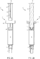
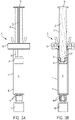
- the controlled delivery syringe device 10 includes a syringe barrel 12 having a proximal end 14 and a distal end 16.
- the syringe barrel defines a chamber 20 configured for containing an injectable material.
- the distal end 16 can include an opening, such as a luer lock opening 18, through which the injectable material can be expelled and a protective cap 19. It can be appreciated that other types of attachment arrangements can be provided for securing the distal end 16 of the syringe barrel 12 for expelling the injectable material into a target location.
- a plunger rod 22 is associated with the syringe barrel 12.
- the plunger rod 22 includes a proximal end 23 and a distal end 24.
- a plunger or stopper 26 is associated with or secured to the distal end 24 of the plunger rod 22.
- the plunger rod 22 can be threadedly secured to the plunger 26, as shown by 27 in Fig. 2B . It can be appreciated that the plunger rod 22 and plunger 26 can be secured by other techniques known in the art.
- the plunger 26 is axially movable within the syringe barrel 12 to expel fluid from the opening 18 of the syringe barrel 12.
- the plunger rod 22 can also include a thumb press 28 located at the proximal end 23 of the plunger rod 22.
- a plurality of equally spaced periodic features 30, such as teeth, are provided on at least a portion of the plunger rod 22.
- the periodic features or teeth 30 can be located on one side of the plunger rod 22 or alternatively a set of teeth can be located on opposite sides of the plunger rod 22. According to one design, the periodic features or teeth 30 can be notched out of oppositely disposed splines 32 of the plunger rod 22.
- a counter member is engageable with the periodic features or teeth 30.
- the periodic features or teeth 30 can be shaped and oriented to cooperate with the counter member 40 during advancement of the plunger in the syringe barrel 12 to produce a sudden change in the actuation force, thus, generating a tactile signal upon application of a metered dose.
- the periodic feature or teeth 30 can include a flat surface 34 located behind each of the teeth 30 and a tapered or angled portion 36 that extends from the flat surface 34 and tapers downwardly in an inward direction with respect to a longitudinal axis L extending through the plunger rod 22.
- the counter member 40 includes a collar 42 that can be retrofitted and/or permanently attached to the proximal end 14 of the syringe barrel 12. This collar 42 can overhang the rear opening of the syringe barrel 12. As shown in the figures, the collar 42 can be formed of a plurality of interconnecting pieces that can be clamped about the rear collar 44 of the syringe barrel 12.
- the counter member 40 can include either one or a pair of tabs 46 that include an engagement end 47 that interacts or engages with the periodic features or teeth 30.
- application of the distally direct force to the plunger rod 22 results in disengagement and reengagement of the engagement end 47 of the tabs 46 with sequentially arranged periodic features or teeth 30 on the plunger rod 22.
- the engagement ends 47 of the tabs 46 are deflected from an initial state, as shown in Fig.
- the tabs 46 are configured such that they automatically lock onto the teeth 30 when in an unbiased or non-actuated state. According to one example, the tactile feedback occurring from the engagement end 47 of the tab 46 deflecting over the toothed plunger rod 22 was measured and it was found that for approximately every 5 mm of displacement, a noticeable increase and decrease in force of about 1 N was measured when the teeth 30 passed the engagement end 47 of the deflecting tab 46.
- the plunger rod 22 can include the thumb press 28 located at the proximal end 23 of the plunger rod 22 for receiving the distally directed force applied by the medical practitioner resulting in the disengagement and reengagement of the tabs 46 of the counter member 40 with sequentially spaced periodic features or teeth 30 on the plunger rod 22.
- An actuating member can be provided that includes the at least one tab 46, which is associated with the counter member 40.
- the at least one tab or tabs 46 can include finger press ends 48.
- a squeezing force can be applied to the finger press ends 48 of the tab 46, causing the engagement ends 47 to pivot in an outward direction, resulting in disengagement and reengagement of the counter member with sequentially spaced periodic features or teeth 30 on the plunger rod 22.
- the actuating member enables the technician to retract the plunger during administration of the injectable material.
- the tabs 46 are configured such that they can be squeezed out of the way when desired, but automatically lock onto the plunger rod teeth 30 when they are not being squeezed.
- the geometry of the tab 46 is such that the deflection of the tab 46 when advancing the plunger rod 22 is maximized for a given actuation force.
- the geometry of the tab 46 can include a vertical reinforcing member (not shown), to stiffen the tab 46 to withstand pressure from a dialysis line.
- An advantage of this invention is that it allows the medical practitioner to count the number of times a "click" is felt during the administration of the injectable material. Since the spacing between the "clicks" is equivalent to a prescribed volume, the practitioner will readily know how much volume has been injected without looking at the graduations on the syringe barrel 12. For example, if the spacing between two neighboring periodic features or teeth 30 on the plunger rod 22 correspond to a 0.2 ml volume, the practitioner will know that a volume of 1 ml has been delivered after counting five "clicks". Another advantage of the invention is that it prevents backward travel of the plunger rod 22 before exiting the barrel.
Landscapes
- Health & Medical Sciences (AREA)
- Vascular Medicine (AREA)
- Engineering & Computer Science (AREA)
- Anesthesiology (AREA)
- Biomedical Technology (AREA)
- Heart & Thoracic Surgery (AREA)
- Hematology (AREA)
- Life Sciences & Earth Sciences (AREA)
- Animal Behavior & Ethology (AREA)
- General Health & Medical Sciences (AREA)
- Public Health (AREA)
- Veterinary Medicine (AREA)
- Infusion, Injection, And Reservoir Apparatuses (AREA)
Claims (7)
- Dispositif de type seringue à administration contrôlée (10) comprenant :un corps de seringue (12) ayant une extrémité proximale (14) et une extrémité distale (16) et définissant une chambre (20) dans celui-ci, la chambre (20) étant configurée pour contenir une matière injectable ;une tige de piston (22) associée au corps de seringue (12) ;un piston (26) fixé à la tige de piston (22) et mobile axialement dans le corps de seringue (12) ;une pluralité d'éléments périodiques (30) espacés de manière égale et séquentielle associés à au moins une partie de la tige de piston (22) et ;un élément de comptage (40) pouvant s'engager avec les éléments périodiques (30),dans lequel l'application d'une force dirigée de manière distale à la tige de piston (22) entraîne le désengagement et le réengagement de l'élément de comptage (40) avec les éléments périodiques (30) espacés de manière séquentielle sur la tige de piston (22), permettant l'avancement de la tige de piston (22) et du piston (26) dans le corps de seringue (12) tout en fournissant une rétroaction tactile de progression de dose de la matière injectable ;caractérisé en ce queles éléments périodiques (30) sont prévus sur des côtés disposés de manière opposée de la tige de piston (22) ;l'élément de comptage (40) comprenant une paire de languettes (46) disposées de manière opposée, chaque languette (46) comprenant une extrémité d'engagement (47) et une extrémité de pression de doigt (48), où l'extrémité d'engagement (47) s'engage avec les éléments périodiques (30) ; etdans lequel chaque languette (46) est configurée pour pivoter lors de l'application d'une force de pincement à l'extrémité de pression de doigt (48) de chaque languette (46), amenant l'extrémité d'engagement (47) de chaque languette (46) à se désengager des éléments périodiques (30), permettant la rétraction ou l'avancement de la tige de piston (22) et du piston (26) dans le corps de seringue (12).
- Dispositif (10) de la revendication 1, dans lequel la tige de piston (22) comprend un élément de pression de pouce (28) situé au niveau d'une extrémité proximale (23) de la tige de piston (22) pour recevoir l'application de la force dirigée de manière distale à la tige de piston (22) et où les éléments périodiques (30) sont effilés pour appliquer une force dirigée vers l'extérieur à l'élément de comptage (40) entraînant le désengagement et le réengagement de l'élément de comptage (40) avec les éléments périodiques (30) espacés de manière séquentielle sur la tige de piston (22).
- Dispositif (10) de la revendication 1, dans lequel l'élément de comptage (40) comprend un collier (42) configuré pour être serré autour d'une extrémité proximale (14) du corps de seringue (12), dans lequel le collier (42) de l'élément de comptage (40) comprend de préférence une pluralité de composants séparables capables d'être fixés de manière permanente autour d'une bride du corps de seringue, de sorte que le collier (42) de l'élément de comptage (40) surplombe une ouverture arrière du corps de seringue (12).
- Dispositif de la revendication 1, dans lequel les éléments périodiques (30) sont configurés pour empêcher le retrait involontaire de la tige de piston (22) hors du corps de seringue (12).
- Procédé d'équipement d'une seringue d'un dispositif (10) pour injecter une dose mesurée de matière injectable comprenant :la fourniture d'un corps de seringue (12) ayant une extrémité proximale (14) et une extrémité distale (16) définissant une chambre (20) dans celui-ci, la chambre (20) étant configurée pour contenir une matière injectable ;la fourniture d'une tige de piston (22) ayant une extrémité proximale (23) et une extrémité distale (24) et d'un piston (26) fixé à l'extrémité distale (24) de celle-ci, la tige de piston (22) comprenant en outre une pluralité d'éléments périodiques (30) espacés de manière égale et séquentielle situés sur celle-ci ;l'association de la tige de piston (22) et du piston (26) au corps de seringue (12) de sorte que le piston (26) soit mobile axialement dans le corps de seringue (12) ;la fixation d'un élément de comptage (40) sur une extrémité proximale (14) du corps de seringue (12), l'élément de comptage (40) comprenant une paire de languettes (46) disposées de manière opposée, chaque languette (46) comprenant une extrémité d'engagement (47) et une extrémité de pression de doigt (48), dans lequel l'extrémité d'engagement (47) s'engage avec les éléments périodiques (30) ;dans lequel les éléments périodiques (30) sont prévus sur des côtés disposés de manière opposée de la tige de piston (22) ;dans lequel l'application d'une force dirigée de manière distale à la tige de piston (22) entraîne le désengagement et le réengagement de l'élément de comptage (40) avec une pluralité d'éléments périodiques (30) espacés de manière séquentielle sur la tige de piston (22), permettant l'avancement de la tige de piston (22) et du piston (26) dans le corps de seringue (12) tout en fournissant une rétroaction tactile de progression de dose de la matière injectable et dans lequel l'application d'une force à l'extrémité de pression de doigt (48) permet la rétraction du piston (26) ; etdans lequel chaque languette (46) est configurée pour pivoter lors de l'application d'une force de pincement à l'extrémité de pression de doigt (48) de chaque languette (46), amenant l'extrémité d'engagement (47) de chaque languette (46) à se désengager des éléments périodiques (30), permettant la rétraction ou l'avancement de la tige de piston (22) et du piston (26) dans le corps de seringue (12).
- Procédé de la revendication 5, dans lequel la tige de piston (22) comprend un élément de pression de pouce (28) situé au niveau d'une extrémité proximale (23) de la tige de piston (22) pour recevoir l'application de la force dirigée de manière distale à la tige de piston (22) et dans lequel les éléments périodiques (30) sont effilés pour appliquer une force dirigée vers l'extérieur à l'élément de comptage (40) entraînant le désengagement et le réengagement de l'élément de comptage (40) avec les éléments périodiques (30) espacés de manière séquentielle sur la tige de piston (22).
- Procédé de la revendication 5, dans lequel l'élément de comptage (40) comprend un collier (42) configuré pour être serré autour d'une extrémité proximale (14) du corps de seringue (12), dans lequel le collier (42) de l'élément de comptage (40) comprend de préférence une pluralité de composants séparables et dans lequel le procédé d'équipement de la seringue comprend la fixation permanente des composants séparables autour d'une bride du corps de seringue (12), de sorte que le collier de l'élément de comptage surplombe une ouverture arrière du corps de seringue (12).
Priority Applications (1)
| Application Number | Priority Date | Filing Date | Title |
|---|---|---|---|
| EP22190390.9A EP4129366B1 (fr) | 2017-04-13 | 2018-04-05 | Dispositif de type seringue à distribution contrôlée |
Applications Claiming Priority (2)
| Application Number | Priority Date | Filing Date | Title |
|---|---|---|---|
| US201762485056P | 2017-04-13 | 2017-04-13 | |
| PCT/US2018/026222 WO2018191101A1 (fr) | 2017-04-13 | 2018-04-05 | Dispositif de type seringue à distribution contrôlée |
Related Child Applications (1)
| Application Number | Title | Priority Date | Filing Date |
|---|---|---|---|
| EP22190390.9A Division EP4129366B1 (fr) | 2017-04-13 | 2018-04-05 | Dispositif de type seringue à distribution contrôlée |
Publications (2)
| Publication Number | Publication Date |
|---|---|
| EP3609559A1 EP3609559A1 (fr) | 2020-02-19 |
| EP3609559B1 true EP3609559B1 (fr) | 2022-08-17 |
Family
ID=62063232
Family Applications (2)
| Application Number | Title | Priority Date | Filing Date |
|---|---|---|---|
| EP18720498.7A Active EP3609559B1 (fr) | 2017-04-13 | 2018-04-05 | Dispositif de type seringue à distribution contrôlée |
| EP22190390.9A Active EP4129366B1 (fr) | 2017-04-13 | 2018-04-05 | Dispositif de type seringue à distribution contrôlée |
Family Applications After (1)
| Application Number | Title | Priority Date | Filing Date |
|---|---|---|---|
| EP22190390.9A Active EP4129366B1 (fr) | 2017-04-13 | 2018-04-05 | Dispositif de type seringue à distribution contrôlée |
Country Status (5)
| Country | Link |
|---|---|
| US (1) | US11628258B2 (fr) |
| EP (2) | EP3609559B1 (fr) |
| CN (1) | CN110709122B (fr) |
| SG (1) | SG11201909548RA (fr) |
| WO (1) | WO2018191101A1 (fr) |
Families Citing this family (3)
| Publication number | Priority date | Publication date | Assignee | Title |
|---|---|---|---|---|
| USD834182S1 (en) * | 2017-06-20 | 2018-11-20 | Genesis Cosmetics LLC | Syringe |
| MX2021012304A (es) * | 2019-04-09 | 2021-12-15 | Congruence Medical Solutions Llc | Dispositivo de inyeccion. |
| CN113509613B (zh) * | 2021-06-08 | 2023-08-15 | 珠海丽笙医疗科技有限公司 | 一种环柄注射器的使用方法 |
Family Cites Families (18)
| Publication number | Priority date | Publication date | Assignee | Title |
|---|---|---|---|---|
| US4466426A (en) * | 1981-06-29 | 1984-08-21 | Blackman Seymour N | Syringe with actinic ray blocking stripe |
| JPS6130699U (ja) * | 1984-07-26 | 1986-02-24 | 三菱鉛筆株式会社 | 注入器 |
| US4915695A (en) * | 1988-09-12 | 1990-04-10 | Koobs David C | Multiple barrel syringe |
| US7611495B1 (en) * | 2005-10-07 | 2009-11-03 | Gianturco Michael C | Device for manually controlling delivery rate of a hypodermic syringe and syringe having same |
| EP2257323B1 (fr) | 2008-01-30 | 2019-05-29 | Becton Dickinson France | Dispositif d'administration à division de doses |
| US9186464B2 (en) | 2008-05-15 | 2015-11-17 | Allergan, Inc. | Dosing injector |
| CN102065939B (zh) * | 2008-06-17 | 2013-06-19 | 电气化学工业株式会社 | 注射器 |
| JP5622743B2 (ja) * | 2008-12-04 | 2014-11-12 | サノフィ−アベンティス・ドイチュラント・ゲゼルシャフト・ミット・ベシュレンクテル・ハフツング | ピストンロッドの意図しない動きを防ぐための保持手段を有する注射デバイス |
| US20110046559A1 (en) * | 2009-08-21 | 2011-02-24 | Becton Dickinson France S.A.S. | Syringe Assembly Having a Flexible or Slidable Flange |
| JP5969464B2 (ja) | 2011-03-29 | 2016-08-17 | テルモ株式会社 | シリンジ |
| BR112014005465A2 (pt) * | 2011-09-09 | 2017-03-21 | Merck Patent Gmbh | autoinjetor com injeção de agulha separada |
| BR112015017599A2 (pt) * | 2013-01-30 | 2017-10-03 | Terrence Armstrong Sean | Seringa |
| US9597463B2 (en) * | 2013-03-14 | 2017-03-21 | Boston Scientific Scimed, Inc. | Injection devices with controllable depth adjustability and methods of use |
| US20140350516A1 (en) * | 2013-05-23 | 2014-11-27 | Allergan, Inc. | Mechanical syringe accessory |
| CN106029137B (zh) * | 2014-01-21 | 2020-05-15 | 肠外技术有限责任公司 | 力致动的注射装置 |
| US20160144122A1 (en) * | 2014-11-26 | 2016-05-26 | Fisher Clinical Services GmbH | Syringe Assembly with Plunger Rod Backstop and Method of Use |
| PT3072547T (pt) * | 2015-03-25 | 2019-02-26 | Q Med Ab | Seringa com curso indexado |
| US10532163B2 (en) | 2016-07-02 | 2020-01-14 | Gennady Kleyman | Fluid dispensing device |
-
2018
- 2018-04-05 EP EP18720498.7A patent/EP3609559B1/fr active Active
- 2018-04-05 US US16/604,396 patent/US11628258B2/en active Active
- 2018-04-05 CN CN201880036409.5A patent/CN110709122B/zh active Active
- 2018-04-05 SG SG11201909548R patent/SG11201909548RA/en unknown
- 2018-04-05 WO PCT/US2018/026222 patent/WO2018191101A1/fr unknown
- 2018-04-05 EP EP22190390.9A patent/EP4129366B1/fr active Active
Also Published As
| Publication number | Publication date |
|---|---|
| SG11201909548RA (en) | 2019-11-28 |
| US11628258B2 (en) | 2023-04-18 |
| EP4129366A1 (fr) | 2023-02-08 |
| EP3609559A1 (fr) | 2020-02-19 |
| EP4129366B1 (fr) | 2024-03-27 |
| WO2018191101A1 (fr) | 2018-10-18 |
| CN110709122A (zh) | 2020-01-17 |
| CN110709122B (zh) | 2023-04-11 |
| US20200121857A1 (en) | 2020-04-23 |
| EP4129366C0 (fr) | 2024-03-27 |
Similar Documents
| Publication | Publication Date | Title |
|---|---|---|
| EP3142728B1 (fr) | Dispositif de dosage pour la perfusion d'un medicament liquide d'une cartouche comprenant une tige telescopique pour deplacer le piston | |
| JP6223945B2 (ja) | 薬物送達器材 | |
| JP3989437B2 (ja) | 分配可能な製品の投与分を投与する投与装置のケーシング部分の接続 | |
| EP2063937B1 (fr) | Dispositif de protection d'aiguille présentant une position de protection bloquée | |
| EP3609559B1 (fr) | Dispositif de type seringue à distribution contrôlée | |
| EP2755702B1 (fr) | Tige de piston avec moyens de dosage et dispositif d'injection | |
| US8905975B2 (en) | Container, device and method to store and expel a product | |
| EP3068472B1 (fr) | Dispositif d'accès | |
| EP1711218A2 (fr) | Dispositif d'injection a element de dosage enclenchable | |
| WO2015160600A1 (fr) | Dispositif d'administration de médicament | |
| JP2011528573A (ja) | 皮内投与システムのためのカートリッジストッパー | |
| US11413396B2 (en) | Assisted injection device for selectively injecting a composition contained in a medical container | |
| CN111372631B (zh) | 用于无菌地转移流体的连接器 | |
| JP2023021444A (ja) | 高い投与量精度の薬物送達のためのシリンジプランジャーストッパー | |
| JP7432097B2 (ja) | 注射プロセス中に自動的かつ受動的に針の安全を提供する超低用量の廃棄物のニードルおよび注射器システム | |
| WO2004096326A1 (fr) | Systeme de seringue | |
| EP3254714B1 (fr) | Dispositif et systeme de distribution d'un fluide dans des conditions aseptiques | |
| US20200405974A1 (en) | Ultra-Low Waste Disposable Syringe with Self-Adjusting Integrated Safety Features | |
| EP3436109B1 (fr) | Seringue à piston souple | |
| AU2007202204B2 (en) | Locking device for connecting housing sections of an administration appliance | |
| JP2023049801A (ja) | 注射器 | |
| JP2022509364A (ja) | 予め充填された安全針と注射器システム | |
| DE102014006323A1 (de) | Vorgefüllte Spritze mit Wiederverwendungsschutz |
Legal Events
| Date | Code | Title | Description |
|---|---|---|---|
| STAA | Information on the status of an ep patent application or granted ep patent |
Free format text: STATUS: UNKNOWN |
|
| STAA | Information on the status of an ep patent application or granted ep patent |
Free format text: STATUS: THE INTERNATIONAL PUBLICATION HAS BEEN MADE |
|
| PUAI | Public reference made under article 153(3) epc to a published international application that has entered the european phase |
Free format text: ORIGINAL CODE: 0009012 |
|
| STAA | Information on the status of an ep patent application or granted ep patent |
Free format text: STATUS: REQUEST FOR EXAMINATION WAS MADE |
|
| 17P | Request for examination filed |
Effective date: 20191029 |
|
| AK | Designated contracting states |
Kind code of ref document: A1 Designated state(s): AL AT BE BG CH CY CZ DE DK EE ES FI FR GB GR HR HU IE IS IT LI LT LU LV MC MK MT NL NO PL PT RO RS SE SI SK SM TR |
|
| AX | Request for extension of the european patent |
Extension state: BA ME |
|
| DAV | Request for validation of the european patent (deleted) | ||
| DAX | Request for extension of the european patent (deleted) | ||
| STAA | Information on the status of an ep patent application or granted ep patent |
Free format text: STATUS: EXAMINATION IS IN PROGRESS |
|
| 17Q | First examination report despatched |
Effective date: 20200910 |
|
| STAA | Information on the status of an ep patent application or granted ep patent |
Free format text: STATUS: EXAMINATION IS IN PROGRESS |
|
| GRAP | Despatch of communication of intention to grant a patent |
Free format text: ORIGINAL CODE: EPIDOSNIGR1 |
|
| STAA | Information on the status of an ep patent application or granted ep patent |
Free format text: STATUS: GRANT OF PATENT IS INTENDED |
|
| INTG | Intention to grant announced |
Effective date: 20220302 |
|
| GRAS | Grant fee paid |
Free format text: ORIGINAL CODE: EPIDOSNIGR3 |
|
| GRAA | (expected) grant |
Free format text: ORIGINAL CODE: 0009210 |
|
| STAA | Information on the status of an ep patent application or granted ep patent |
Free format text: STATUS: THE PATENT HAS BEEN GRANTED |
|
| AK | Designated contracting states |
Kind code of ref document: B1 Designated state(s): AL AT BE BG CH CY CZ DE DK EE ES FI FR GB GR HR HU IE IS IT LI LT LU LV MC MK MT NL NO PL PT RO RS SE SI SK SM TR |
|
| REG | Reference to a national code |
Ref country code: CH Ref legal event code: EP |
|
| REG | Reference to a national code |
Ref country code: DE Ref legal event code: R096 Ref document number: 602018039381 Country of ref document: DE |
|
| REG | Reference to a national code |
Ref country code: IE Ref legal event code: FG4D |
|
| REG | Reference to a national code |
Ref country code: AT Ref legal event code: REF Ref document number: 1511751 Country of ref document: AT Kind code of ref document: T Effective date: 20220915 |
|
| REG | Reference to a national code |
Ref country code: NL Ref legal event code: MP Effective date: 20220817 |
|
| REG | Reference to a national code |
Ref country code: LT Ref legal event code: MG9D |
|
| PG25 | Lapsed in a contracting state [announced via postgrant information from national office to epo] |
Ref country code: SE Free format text: LAPSE BECAUSE OF FAILURE TO SUBMIT A TRANSLATION OF THE DESCRIPTION OR TO PAY THE FEE WITHIN THE PRESCRIBED TIME-LIMIT Effective date: 20220817 Ref country code: RS Free format text: LAPSE BECAUSE OF FAILURE TO SUBMIT A TRANSLATION OF THE DESCRIPTION OR TO PAY THE FEE WITHIN THE PRESCRIBED TIME-LIMIT Effective date: 20220817 Ref country code: PT Free format text: LAPSE BECAUSE OF FAILURE TO SUBMIT A TRANSLATION OF THE DESCRIPTION OR TO PAY THE FEE WITHIN THE PRESCRIBED TIME-LIMIT Effective date: 20221219 Ref country code: NO Free format text: LAPSE BECAUSE OF FAILURE TO SUBMIT A TRANSLATION OF THE DESCRIPTION OR TO PAY THE FEE WITHIN THE PRESCRIBED TIME-LIMIT Effective date: 20221117 Ref country code: NL Free format text: LAPSE BECAUSE OF FAILURE TO SUBMIT A TRANSLATION OF THE DESCRIPTION OR TO PAY THE FEE WITHIN THE PRESCRIBED TIME-LIMIT Effective date: 20220817 Ref country code: LV Free format text: LAPSE BECAUSE OF FAILURE TO SUBMIT A TRANSLATION OF THE DESCRIPTION OR TO PAY THE FEE WITHIN THE PRESCRIBED TIME-LIMIT Effective date: 20220817 Ref country code: LT Free format text: LAPSE BECAUSE OF FAILURE TO SUBMIT A TRANSLATION OF THE DESCRIPTION OR TO PAY THE FEE WITHIN THE PRESCRIBED TIME-LIMIT Effective date: 20220817 Ref country code: FI Free format text: LAPSE BECAUSE OF FAILURE TO SUBMIT A TRANSLATION OF THE DESCRIPTION OR TO PAY THE FEE WITHIN THE PRESCRIBED TIME-LIMIT Effective date: 20220817 |
|
| REG | Reference to a national code |
Ref country code: AT Ref legal event code: MK05 Ref document number: 1511751 Country of ref document: AT Kind code of ref document: T Effective date: 20220817 |
|
| PG25 | Lapsed in a contracting state [announced via postgrant information from national office to epo] |
Ref country code: PL Free format text: LAPSE BECAUSE OF FAILURE TO SUBMIT A TRANSLATION OF THE DESCRIPTION OR TO PAY THE FEE WITHIN THE PRESCRIBED TIME-LIMIT Effective date: 20220817 Ref country code: IS Free format text: LAPSE BECAUSE OF FAILURE TO SUBMIT A TRANSLATION OF THE DESCRIPTION OR TO PAY THE FEE WITHIN THE PRESCRIBED TIME-LIMIT Effective date: 20221217 Ref country code: HR Free format text: LAPSE BECAUSE OF FAILURE TO SUBMIT A TRANSLATION OF THE DESCRIPTION OR TO PAY THE FEE WITHIN THE PRESCRIBED TIME-LIMIT Effective date: 20220817 Ref country code: GR Free format text: LAPSE BECAUSE OF FAILURE TO SUBMIT A TRANSLATION OF THE DESCRIPTION OR TO PAY THE FEE WITHIN THE PRESCRIBED TIME-LIMIT Effective date: 20221118 |
|
| PG25 | Lapsed in a contracting state [announced via postgrant information from national office to epo] |
Ref country code: SM Free format text: LAPSE BECAUSE OF FAILURE TO SUBMIT A TRANSLATION OF THE DESCRIPTION OR TO PAY THE FEE WITHIN THE PRESCRIBED TIME-LIMIT Effective date: 20220817 Ref country code: RO Free format text: LAPSE BECAUSE OF FAILURE TO SUBMIT A TRANSLATION OF THE DESCRIPTION OR TO PAY THE FEE WITHIN THE PRESCRIBED TIME-LIMIT Effective date: 20220817 Ref country code: ES Free format text: LAPSE BECAUSE OF FAILURE TO SUBMIT A TRANSLATION OF THE DESCRIPTION OR TO PAY THE FEE WITHIN THE PRESCRIBED TIME-LIMIT Effective date: 20220817 Ref country code: DK Free format text: LAPSE BECAUSE OF FAILURE TO SUBMIT A TRANSLATION OF THE DESCRIPTION OR TO PAY THE FEE WITHIN THE PRESCRIBED TIME-LIMIT Effective date: 20220817 Ref country code: CZ Free format text: LAPSE BECAUSE OF FAILURE TO SUBMIT A TRANSLATION OF THE DESCRIPTION OR TO PAY THE FEE WITHIN THE PRESCRIBED TIME-LIMIT Effective date: 20220817 Ref country code: AT Free format text: LAPSE BECAUSE OF FAILURE TO SUBMIT A TRANSLATION OF THE DESCRIPTION OR TO PAY THE FEE WITHIN THE PRESCRIBED TIME-LIMIT Effective date: 20220817 |
|
| PGFP | Annual fee paid to national office [announced via postgrant information from national office to epo] |
Ref country code: FR Payment date: 20230321 Year of fee payment: 6 |
|
| REG | Reference to a national code |
Ref country code: DE Ref legal event code: R097 Ref document number: 602018039381 Country of ref document: DE |
|
| PG25 | Lapsed in a contracting state [announced via postgrant information from national office to epo] |
Ref country code: SK Free format text: LAPSE BECAUSE OF FAILURE TO SUBMIT A TRANSLATION OF THE DESCRIPTION OR TO PAY THE FEE WITHIN THE PRESCRIBED TIME-LIMIT Effective date: 20220817 Ref country code: EE Free format text: LAPSE BECAUSE OF FAILURE TO SUBMIT A TRANSLATION OF THE DESCRIPTION OR TO PAY THE FEE WITHIN THE PRESCRIBED TIME-LIMIT Effective date: 20220817 |
|
| PLBE | No opposition filed within time limit |
Free format text: ORIGINAL CODE: 0009261 |
|
| STAA | Information on the status of an ep patent application or granted ep patent |
Free format text: STATUS: NO OPPOSITION FILED WITHIN TIME LIMIT |
|
| PG25 | Lapsed in a contracting state [announced via postgrant information from national office to epo] |
Ref country code: AL Free format text: LAPSE BECAUSE OF FAILURE TO SUBMIT A TRANSLATION OF THE DESCRIPTION OR TO PAY THE FEE WITHIN THE PRESCRIBED TIME-LIMIT Effective date: 20220817 |
|
| 26N | No opposition filed |
Effective date: 20230519 |
|
| PGFP | Annual fee paid to national office [announced via postgrant information from national office to epo] |
Ref country code: DE Payment date: 20230321 Year of fee payment: 6 |
|
| PG25 | Lapsed in a contracting state [announced via postgrant information from national office to epo] |
Ref country code: SI Free format text: LAPSE BECAUSE OF FAILURE TO SUBMIT A TRANSLATION OF THE DESCRIPTION OR TO PAY THE FEE WITHIN THE PRESCRIBED TIME-LIMIT Effective date: 20220817 |
|
| REG | Reference to a national code |
Ref country code: CH Ref legal event code: PL |
|
| PG25 | Lapsed in a contracting state [announced via postgrant information from national office to epo] |
Ref country code: LU Free format text: LAPSE BECAUSE OF NON-PAYMENT OF DUE FEES Effective date: 20230405 |
|
| REG | Reference to a national code |
Ref country code: BE Ref legal event code: MM Effective date: 20230430 |
|
| PG25 | Lapsed in a contracting state [announced via postgrant information from national office to epo] |
Ref country code: MC Free format text: LAPSE BECAUSE OF FAILURE TO SUBMIT A TRANSLATION OF THE DESCRIPTION OR TO PAY THE FEE WITHIN THE PRESCRIBED TIME-LIMIT Effective date: 20220817 |
|
| PG25 | Lapsed in a contracting state [announced via postgrant information from national office to epo] |
Ref country code: MC Free format text: LAPSE BECAUSE OF FAILURE TO SUBMIT A TRANSLATION OF THE DESCRIPTION OR TO PAY THE FEE WITHIN THE PRESCRIBED TIME-LIMIT Effective date: 20220817 Ref country code: LI Free format text: LAPSE BECAUSE OF NON-PAYMENT OF DUE FEES Effective date: 20230430 Ref country code: CH Free format text: LAPSE BECAUSE OF NON-PAYMENT OF DUE FEES Effective date: 20230430 |
|
| REG | Reference to a national code |
Ref country code: IE Ref legal event code: MM4A |
|
| PG25 | Lapsed in a contracting state [announced via postgrant information from national office to epo] |
Ref country code: BE Free format text: LAPSE BECAUSE OF NON-PAYMENT OF DUE FEES Effective date: 20230430 |
|
| PG25 | Lapsed in a contracting state [announced via postgrant information from national office to epo] |
Ref country code: IE Free format text: LAPSE BECAUSE OF NON-PAYMENT OF DUE FEES Effective date: 20230405 |
|
| PG25 | Lapsed in a contracting state [announced via postgrant information from national office to epo] |
Ref country code: IE Free format text: LAPSE BECAUSE OF NON-PAYMENT OF DUE FEES Effective date: 20230405 |
|
| PGFP | Annual fee paid to national office [announced via postgrant information from national office to epo] |
Ref country code: GB Payment date: 20240320 Year of fee payment: 7 |