EP3609379B1 - Cyclone separator and handheld vacuum cleaner - Google Patents
Cyclone separator and handheld vacuum cleaner Download PDFInfo
- Publication number
- EP3609379B1 EP3609379B1 EP18784476.6A EP18784476A EP3609379B1 EP 3609379 B1 EP3609379 B1 EP 3609379B1 EP 18784476 A EP18784476 A EP 18784476A EP 3609379 B1 EP3609379 B1 EP 3609379B1
- Authority
- EP
- European Patent Office
- Prior art keywords
- filter media
- vacuum cleaner
- cyclone separator
- strainer
- media assembly
- Prior art date
- Legal status (The legal status is an assumption and is not a legal conclusion. Google has not performed a legal analysis and makes no representation as to the accuracy of the status listed.)
- Active
Links
Images




Classifications
-
- A—HUMAN NECESSITIES
- A47—FURNITURE; DOMESTIC ARTICLES OR APPLIANCES; COFFEE MILLS; SPICE MILLS; SUCTION CLEANERS IN GENERAL
- A47L—DOMESTIC WASHING OR CLEANING; SUCTION CLEANERS IN GENERAL
- A47L5/00—Structural features of suction cleaners
- A47L5/12—Structural features of suction cleaners with power-driven air-pumps or air-compressors, e.g. driven by motor vehicle engine vacuum
- A47L5/22—Structural features of suction cleaners with power-driven air-pumps or air-compressors, e.g. driven by motor vehicle engine vacuum with rotary fans
- A47L5/24—Hand-supported suction cleaners
-
- A—HUMAN NECESSITIES
- A47—FURNITURE; DOMESTIC ARTICLES OR APPLIANCES; COFFEE MILLS; SPICE MILLS; SUCTION CLEANERS IN GENERAL
- A47L—DOMESTIC WASHING OR CLEANING; SUCTION CLEANERS IN GENERAL
- A47L9/00—Details or accessories of suction cleaners, e.g. mechanical means for controlling the suction or for effecting pulsating action; Storing devices specially adapted to suction cleaners or parts thereof; Carrying-vehicles specially adapted for suction cleaners
- A47L9/10—Filters; Dust separators; Dust removal; Automatic exchange of filters
- A47L9/12—Dry filters
- A47L9/127—Dry filters tube- or sleeve-shaped
-
- A—HUMAN NECESSITIES
- A47—FURNITURE; DOMESTIC ARTICLES OR APPLIANCES; COFFEE MILLS; SPICE MILLS; SUCTION CLEANERS IN GENERAL
- A47L—DOMESTIC WASHING OR CLEANING; SUCTION CLEANERS IN GENERAL
- A47L9/00—Details or accessories of suction cleaners, e.g. mechanical means for controlling the suction or for effecting pulsating action; Storing devices specially adapted to suction cleaners or parts thereof; Carrying-vehicles specially adapted for suction cleaners
- A47L9/10—Filters; Dust separators; Dust removal; Automatic exchange of filters
- A47L9/16—Arrangement or disposition of cyclones or other devices with centrifugal action
- A47L9/1658—Construction of outlets
- A47L9/1666—Construction of outlets with filtering means
-
- A—HUMAN NECESSITIES
- A47—FURNITURE; DOMESTIC ARTICLES OR APPLIANCES; COFFEE MILLS; SPICE MILLS; SUCTION CLEANERS IN GENERAL
- A47L—DOMESTIC WASHING OR CLEANING; SUCTION CLEANERS IN GENERAL
- A47L9/00—Details or accessories of suction cleaners, e.g. mechanical means for controlling the suction or for effecting pulsating action; Storing devices specially adapted to suction cleaners or parts thereof; Carrying-vehicles specially adapted for suction cleaners
- A47L9/28—Installation of the electric equipment, e.g. adaptation or attachment to the suction cleaner; Controlling suction cleaners by electric means
- A47L9/2868—Arrangements for power supply of vacuum cleaners or the accessories thereof
- A47L9/2884—Details of arrangements of batteries or their installation
Definitions
- one or more filters e.g., a foam type pre-filter is provided to the suction fan to screen out fine dusts or particulates entrained in the airstream flowing from the dust separation compartment before it passes to the suction fan and areas when electrical components are held.
- filters e.g., a foam type pre-filter
- the placement of the pre-filter is located where it is only accessible by opening the dust cup or by disassembling it from the cleaner unit. As often in both cases, the user can be exposed dust and contaminates released from the dust bin. As a result, users' experience of annoyance and inconvenience detracts from the care and maintenance of the pre-filter to the suction fan, one of the most critical components of the vacuum cleaner.
- a handheld vacuum cleaner 1 which comprises a housing 2 having exterior walls 3 forming an enclosure 4.
- a suction fan compartment 6 containing a suction fan and a cyclone separator 8 are provided within the enclosure 4 and separated by a partition wall 12 having an opening 14 between the cyclone separator and the suction fan compartment 6.
- a suction inlet 20 is formed on the wall of the housing enclosure adapted for the introduction of airflow or suction air 15 into the cyclone separator.
- a strainer or mesh assembly 10 is provided where airflow from the cyclone separator 8 is filtered and passed to the suction fan compartment 6.
- the strainer 10 includes a frame 101 forming an open enclosure and defining an interior passageway 104.
- a mesh cover or screen 102 is formed on the strainer frame 101.
- Suction air 15 flows through the strainer 10 and passes the passageway 104 through the partition wall opening 14 and to the suction fan compartment 6.
- a resilient means such as a rubber seal 103 seated between the periphery of the base cover 85 around the access opening 851 and the lower portion of the strainer 10.
- the cyclone separator 8 comprises an upper dust separation or cyclonic separation chamber 81 and a lower dust collection section or dust cup 82.
- Dust cup 82 has a base cover 85 pivotally attached to wall 3 to facilitate the removal of dust accumulated in the dust cup 8.
- the base cover 85 has an access opening 851.
- a filter media assembly 9 passes through the access opening 851 and is removably received in the passageway 104 of the strainer 10 to provide separation of particulates or fine dusts after suction air from the cyclonic separation chamber passes through the strainer.
- sealing means 852 is seated between the periphery of access opening 851 and filter media assembly 9.
- the sealing means 852 may be constructed of a resilient material such as rubber (e.g., a rubber ring/o-ring) or the like.
- the sealing means 852 has a first sealing ring portion 8521 disposed on the exterior side of the base cover 85 around opening 851 and a second sealing ring portion 8522 in the interior side of the base cover 85 at the opening.
- the sealing means 852 is fitted within a channel 853 disposed at the lower end portion of the filter media assembly 9 in engagement with the edge of the access opening 851.
- the filter media assembly 9 and the strainer 10 extend from the dust collection chamber cover 85 toward the partition wall opening 14 and inlet to the suction fan compartment 6.
- suction air 15 ( Fig. 6 ) is introduced into the vacuum cleaner enclosure 4 via the suction inlet 20 along the inside wall surface of the cyclone separator 81.
- the cyclonic flow pattern causes the dust particles carried in the suction airstream to be centrifugally separated from the airflow and collected in the lower portion of the cyclone separator in the dust collection chamber or dust cup 82.
Landscapes
- Engineering & Computer Science (AREA)
- Mechanical Engineering (AREA)
- Filters For Electric Vacuum Cleaners (AREA)
Description
- This disclosure relates to a filtration assembly for a vacuum cleaner. More particularly, this disclosure relates to a concentric filtration assembly for a handheld vacuum cleaner.
- Among various home appliances, hand-held vacuum cleaners have gained popularity in the market place due to their compact, lightweight and portable designs. However, these attractive features often dictate a product design with a limited amount of space for the placement of the parts and components inside the cleaner unit. Consequently, the selection and placement of these parts and components are often resulted as a compromised.
- Because of the compact, lightweight and portable design requirements, a limited amount of space for the appropriate separation and filtration components can have a direct impact on the efficiency, performance and reliability of the cleaner unit. In particular, degradation of cleaner performance is readily observable where large amount of dust or dirt contaminants are captured by the pre-filter of the suction fan blocking the passage of airflow to it or where the pre-filter is damaged. In a worse situation, the dust and contamination of the suction fan or the area housing the electrical components can result in the malfunction of the cleaner unit. These situations can be avoided if proper care is to be taken in the maintenance of the cleaner.
- In a typical hand-held vacuum cleaner, one or more filters, e.g., a foam type pre-filter is provided to the suction fan to screen out fine dusts or particulates entrained in the airstream flowing from the dust separation compartment before it passes to the suction fan and areas when electrical components are held.
- Often, however, due to space limitation, the placement of the pre-filter is located where it is only accessible by opening the dust cup or by disassembling it from the cleaner unit. As often in both cases, the user can be exposed dust and contaminates released from the dust bin. As a result, users' experience of annoyance and inconvenience detracts from the care and maintenance of the pre-filter to the suction fan, one of the most critical components of the vacuum cleaner. Prior art document D1 (
US 2013/160232 A1 ) discloses a vacuum cleaner, which comprises a cyclonic separating apparatus including a dirty air inlet, a main body connected to the cyclonic separating apparatus and a motor and fan unit for generating an airflow through the cyclonic separating apparatus from the dirty air inlet to a clean air outlet, wherein the cyclonic separating apparatus includes at least a first cyclonic cleaning stage and an elongate filter arranged fluidly downstream from the first cyclonic cleaning stage, the elongate filter being housed in a duct at least partially surrounded by the first cleaning stage, and wherein the filter comprises an inlet portion and a filter portion defining a generally tubular filter chamber, the inlet portion including one or more radially facing inlets to permit air to flow into the inlet portion in a radial direction from where the air flows from the inlet portion to the filter chamber in an axial direction (see ABSTRACT of D1). - The present invention provides a handheld vacuum cleaner according to the independent claims. The dependent claims show further examples of a suchlike handheld vacuum cleaner. According to the present invention, a handheld vacuum cleaner 1 is provided which comprises a
housing 2 havingexterior walls 3 forming an enclosure 4. A suction fan compartment 6 containing a suction fan and a cyclone separator 8 are provided within the enclosure 4 and separated by a partition wall 12 having an opening 14 between the cyclone separator and the suction fan compartment 6. Asuction inlet 20 is formed on the wall of the housing enclosure adapted for the introduction of airflow orsuction air 15 into the cyclone separator. At the partition wall opening 14 between the cyclone separator 8 and the suction fan compartment 6, a strainer ormesh assembly 10 is provided where airflow from the cyclone separator 8 is filtered and passed to the suction fan compartment 6. Thestrainer 10 includes aframe 101 forming an open enclosure and defining aninterior passageway 104. A mesh cover orscreen 102 is formed on thestrainer frame 101.Suction air 15 flows through thestrainer 10 and passes thepassageway 104 through the partition wall opening 14 and to the suction fan compartment 6. To achieve air tightness, a resilient means such as arubber seal 103 seated between the periphery of thebase cover 85 around the access opening 851 and the lower portion of thestrainer 10. - The cyclone separator 8 comprises an upper dust separation or
cyclonic separation chamber 81 and a lower dust collection section ordust cup 82.Dust cup 82 has abase cover 85 pivotally attached towall 3 to facilitate the removal of dust accumulated in the dust cup 8. Thebase cover 85 has anaccess opening 851. Afilter media assembly 9 passes through theaccess opening 851 and is removably received in thepassageway 104 of thestrainer 10 to provide separation of particulates or fine dusts after suction air from the cyclonic separation chamber passes through the strainer. - To achieve air tightness and secured placement of the
filter media assembly 9,sealing means 852 is seated between the periphery ofaccess opening 851 andfilter media assembly 9. The sealing means 852 may be constructed of a resilient material such as rubber (e.g., a rubber ring/o-ring) or the like. The sealing means 852 has a firstsealing ring portion 8521 disposed on the exterior side of thebase cover 85 around opening 851 and a secondsealing ring portion 8522 in the interior side of thebase cover 85 at the opening. Thesealing means 852 is fitted within achannel 853 disposed at the lower end portion of thefilter media assembly 9 in engagement with the edge of theaccess opening 851. - The
filter media assembly 9 comprises afilter holder 91 consisting of anopen frame 92 andfilter media 94 disposed outside the holder. Thefilter media assembly 9 is removably fitted in thepassageway 104 ofstrainer 10 and is sealingly secured by the sealing means 852 (e.g., a seal) at thecover access opening 851. - In one embodiment of the present invention, the
strainer 10 andfilter media assembly 9 are substantially cylindrical in shape with thefilter media assembly 9 retrievably received within thepassageway 104 of thestrainer 10. In this embodiment, thestrainer 10 andfilter media assembly 9 can be coaxially aligned or arranged axially parallel to the cyclonic axis of the airflow within the cyclone separator 8. Optionally, thesuction fan 61 can be axially aligned with thefilter media assembly 9. - In another embodiment of the present invention, the
filter media assembly 9 and thestrainer 10 extend from the dustcollection chamber cover 85 toward the partition wall opening 14 and inlet to the suction fan compartment 6. - In summary, the present invention provides a handheld vacuum cleaner wherein air filtration of airflow prior to its entry to the suction fan compartment is provided by a filter media assembly that is directly retrievable from outside the vacuum cleaner housing and without the need for opening the dust cup or removing it from the cleaner body thereby ensuring the performance of the vacuum motor fan and adding to the user's convenience.
- The present invention is described in further details below in conjunction with the accompanying drawings and embodiments.
- The details of embodiments of the present disclosure, both as to their structure and operation, may be gleaned in part by study of the accompanying drawings, in which like reference numerals refer to like parts, and in which:
-
Fig. 1 is a partial cross-sectional view of the handheld vacuum cleaner; -
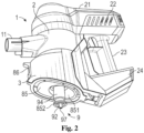
Fig. 2 is a perspective view of an embodiment of a handheld vacuum cleaner ofFig. 1 ; -
Fig. 3 is an enlarged view of element A ofFig. 1 ; -
Fig. 4 is a perspective view of an embodiment of the filter media assembly of the handheld vacuum cleaner ofFig. 1 ; -
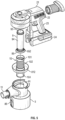
Fig. 5 is an exploded view of the handheld vacuum cleaner ofFig. 1 ; and -
Fig. 6 is a schematic cross sectional view of the handheld vacuum taken along the line 6 - 6 ofFig. 1 . -
Fig. 1 is a perspective view of an embodiment of a handheld vacuum cleaner.Fig. 2 is a perspective view of an embodiment of a handheld vacuum cleaner ofFig. 1 . A handheld vacuum cleaner 1 can have a main body orhousing 2 and dust collection accessories (such as wand and brushes, not shown in the figures) connected thereto. Thehousing 2 can havewalls 3 forming an enclosure 4. The enclosure 4 or housing can be divided into multiple (e.g., two) sections by a partition wall 12 running laterally across the handheld vacuum 1. On one side of the partition wall 12 (e.g., an upper side or end) is a suction fan compartment 6 that can hose a motorized vacuum orsuction fan 61 and associated electronical components. Thesuction fan 61 can provide air suction to the vacuum cleaner 1. On the other side (e.g., a lower end or side) of the partition wall 12 is cyclone separator 8 where dusts and other contaminants in the suction airflow are extracted and collected. The upper portion of the cyclone separator 8 is adapted as acyclonic separation chamber 81. On its lower portion, the cyclone separator 8 provides adust cup 82 for the collection of dusts and other contaminates separated from the suction airflow. - The
dust cup 82 has abase cover 85 pivotally attached to lower portion ofwall 3 and forming its base to facilitate the removal of dust accumulated in the dust separator/collection chamber or dust cup 8. Thebase cover 85 can be opened via a hinge assembly 87 and is held in the closed position by alatch assembly 86. Thebase cover 85 has anaccess opening 851. - The vacuum cleaner can be powered by a power storage means 7 contained in the
handle base 24 as part of the housing enclosure 4, as shown inFigures 1 and2 . The power storage means 7 can be, for example, a rechargeable battery packs for operating thesuction fan 61, its motor, and other parts and accessories of the vacuum cleaner that require power, for example, motorized power brush and lights (not shown). Optionally, an alternative current (AC) source (not shown) may be provided as electric power. - A
suction inlet 20 is provided on thecleaner wall 3 to receive thedust collection pipe 11.Suction inlet 20 is adapted for the introduction of airflow orsuction air 15 into the cyclone separator 8 in a cyclonic fashion. The airflow fromsuction inlet 20 is directed along the inside wall of thecyclonic separation chamber 81 to create a cyclonic flow such that dust, dirt particulates and other contaminates will be separated from the airstream as a result of centrifugal force. - Partition wall 12 has an opening 14. After suction air is centrifuged in the cyclone separator 8, it passes to the suction fan compartment 6 and is exhausted by the
suction fan 61 out of the handheld vacuum cleaner 1 through slottedopenings 22 on thehead cover 21 of thevacuum cleaner body 2. The partition wall opening 14 is positioned about the region where the cyclonic axis of the airflow is located in the cyclone separator. Optionally, thesuction fan 61 is axially aligned with the direction of the flow path passing through the partition wall opening 14 between the cyclone separator and the suction fan compartment. In some embodiments, the partition wall opening 14 can also be concentric with thefilter media assembly 9 and astrainer 10. - At the partition wall opening 14, the
strainer 10 is provided for the airflow orsuction air 15 to pass from the cyclone separator 8 to the suction fan compartment 6.Strainer 10 extends from the partition wall 12 toward thebase cover 85. Thestrainer 10 includes anopen frame 101 forming an enclosure and defining aninterior passageway 104. In thecyclonic separation chamber 81, thestrainer frame 101 is adapted to be open for the suction air to pass through. A mesh orscreen 102 is provided on theopen frame 101 for screening of finer dust, dirt or particulates from the airflow passing from thecyclonic separation chamber 81. Themesh 102 can be formed as part of theopen frame 101. Alternatively, themesh 102 can be provided as a separate cover mounted on theopen frame 101. Thestrainer 10,strainer frame 101 and themesh 102 can be constructed with nylon or metal braided mesh, or by metal etching mesh, and the likes, as known in the art. - To further reduce the undesirable carry-over of finer dusts or dirt into the suction fan compartment, a
filter media assembly 9 is retrievably positioned in thestrainer passageway 104.Fig. 3 is an enlarged view of element A ofFig. 1 .Fig. 4 is a perspective view of an embodiment of the filter media assembly of the handheld vacuum cleaner ofFig. 1 . - Referring to
Fig. 3 andFig. 4 , thefilter media assembly 9 comprises afilter holder 91 having an open or slottedwall 92 and defining an internal pathway 95 (Fig. 6 ) for thesuction air 15 passing from thecyclonic separation chamber 81 to the suction fan compartment 6. At the lower end portion of thefilter media assembly 9, aplug 96 is provided to isolate theinternal pathway 95 of filter media assembly from the outside of the vacuum cleaner. The plug can be constructed of a resilient material such as rubber. To facilitate installation and removal of thefilter media assembly 9, a knob or pull means 97 can be formed as part of theplug 96. - A
filter media 94 disposed outside theholder 91. In one embodiment of the present invention, a sponge material is used as the filter media. While various materials for the construction of thefilter media 94 are known in the art, the choice of the filter media materials, compositions and filtering characteristics are made to achieve the desired dust and contamination removal from the airflow before it enters the suction fan compartment 6 from the dust cup 8. - As shown in
Fig, 1 ,filter media assembly 9 andstrainer 10 are elongated extending from the partition wall 12 to the cycloneseparator base cover 86. In the embodiment shown inFigure 1 ,filter media assembly 9 andstrainer 10 are substantially cylindrical in shape with thefilter media assembly 9 retrievably received within thepassageway 104 of thestrainer 10. In such configuration,filter media assembly 9 andstrainer 10 are coaxially aligned with or arranged axially parallel to thecyclonic axis 100 of thesuction air 15 within thecyclonic separation chamber 81. In some embodiments, thecyclonic axis 100 can be the axis about which the cyclonic flow of the handheld vacuum 1 rotates. Thus, the cyclonic axis can be coincident with acentral axis 99 of thefilter media assembly 9. InFig. 6 , thecyclonic axis 100 is marked with an "x." Thefilter media assembly 9 is thus positioned at the cyclonic center of the cyclone separator 8. - In other embodiments, the
filter media assembly 9 andstrainer 10 are configured in conical or truncated conical shapes wherein thefilter media assembly 9 is nested within the strainer 10 (not shown). As a further option, the suction fan is axially aligned with thefilter media assembly 9. - As referenced above, the cyclone separator 8 has a
base cover 85 pivotally attached to base ofwall 3 to facilitate the removal of dust accumulated in thedust cup 82. Thebase cover 85 has anaccess opening 851. As shown inFig. 1 ,filter media assembly 9 andstrainer 10 extend from the access opening 851 of thebase cover 85 to the partition wall opening 14 of the inlet to the suction fan compartment 6.Filter media assembly 9 can be placed in thestrainer passageway 104 and removed from it through basecover access opening 851. - To achieve air tightness and secured placement of the
filter media assembly 9, sealing means 852 can be seated between the periphery of access opening 851 andfilter media assembly 9. The sealing means 852 may be constructed of a resilient material such as rubber or the likes. The sealing means 852 can have a firstsealing ring portion 8521 disposed on the exterior of thebase cover 85 aroundopening 851 and a secondsealing ring portion 8522 in the interior side of the base cover at the opening. The sealing means 852 is fitted within achannel 853 disposed at the lower end portion of thefilter media assembly 9 in engagement with the edge of theaccess opening 851. - In a similar fashion, the
filter media assembly 9 can be provided with similar sealing means at its upper portion to sealingly secure it around or adjacent to the opening 14 of the wall partition 12. In some embodiments, rubber o-rings or other similar sealing mechanisms can be implemented on either end of thefilter media assembly 9. - To improve the cyclonic separation effect and to reduce remixing of containments with the airstream before it passes to the
strainer 10, anopen shelf 811 is provided in thecyclonic separation chamber 81. Open-shelf 811 has a side wall partially surroundingstrainer 10. The open-shelf 811 can have a cylindrical or tubular body closed at one end with abase tray 812. The open-shell 811 can further have a portion of the cylindrical side wall removed, forming an opening (seeFig. 6 ). Assuction air 15 enterssuction inlet 20, the airstream is directed along the interior wall surface of thecyclonic separation chamber 81 whereby a cyclonic flow is developed. The cyclonic flow creates an inertial particle separator, forcing heavier particulates to the outside of the flow (e.g., against theseparation chamber 81 wall) that ultimately fall to thedust cup 82 and lower portion of the cyclone separator 8. The lighter dust particles may remain in the suction air flow (e.g., suction air 15) and flow into theopen shelf 811 toward thestrainer 10. As heavier particulates are separated from airflow,open shelf 811 helps reduce the remixing of dust particles with the airstream before it enters thestrainer 10. Thebase tray 812 can block flow from the dust cup 8, reducing the reentrainment of dust or dirt in the airflow before it is passed the suction fan compartment 7. Thus, theopen shelf 811 can have a generally cylindrical shape, with a portion of a wall (shown with the dashed lines inFig. 6 ) missing. - In operation, when the vacuum or
suction fan 61 is energized, suction air 15 (Fig. 6 ) is introduced into the vacuum cleaner enclosure 4 via thesuction inlet 20 along the inside wall surface of thecyclone separator 81. The cyclonic flow pattern causes the dust particles carried in the suction airstream to be centrifugally separated from the airflow and collected in the lower portion of the cyclone separator in the dust collection chamber ordust cup 82. - The
centrifugalized airflow 15 can be then passed through the filter mesh orscreen 102 ofstrainer 10 where residual dusts or particulate matters are screened before it enters theinterior passageway 104 ofstrainer 10. Within thepassageway 104, thefilter media assembly 9 is positioned to provide further filtration of the airflow to minimize the intrusion of even finer dust and particulates into the suction fan compartment. - As described above, the
filter media assembly 9 enables the user to position or remove it from the cyclone separator 8 for maintenance without the need for opening the dust cup by way of the base cover 85 (or removing the cyclone separator or dust cup as in the case where the cyclone separator and dust cup may each be adapted to be disassembled from the vacuum cleaner housing). Accordingly, the ease of access to the filter media assembly provides convenience to the users in its maintenance or replacement and reduces the occasion of dust being released out of the dust cup 8 and user annoyance when the base cover of the dust cup is opened or is removed from the vacuum cleaner (as in the case where the cyclone separator as a whole or dust cup is formed as a separable component of the cleaner). As a result, the present invention effectively promotes care in the maintenance of the vacuum cleaner and helps improve the performance of the vacuum motor-fan system when compared with other handheld vacuum cleaners in the market. -
Fig. 5 is an exploded view of the handheld vacuum cleaner ofFig. 1 . As shown, the handheld vacuum cleaner 1 can be formed with thefilter media assembly 9 coaxially received withinstrainer 10. Thestrainer 10 can further be coaxially received within thecyclonic separation chamber 81, which is then contained within the dust cup 8. The exploded view shown is intended to illustrate the interaction of the components of the handheld vacuum cleaner 1 and the relative flow of thesuction air 15 as it flows through the system. -
Fig. 6 is a schematic cross section of the handheld vacuum cleaner ofFig. 1 , taken along the line 6 - 6. As shown, thesuction air 15 can enter thesuction inlet 20. Thesuction air 15 can be forced into a cyclonic flow by the inner wall of the cyclone separator 8. Theopen shelf 811 of thecyclonic separation chamber 81 can allow thesuction air 15 to flow toward thestrainer 10. As shown inFig. 1 andFig. 2 , the suction fan compartment 6 is disposed atop the cyclone separator 8. Thus as shown inFig. 6 , the airflow is directed out of the airpath on the inner portion of thefilter media assembly 9 and into thesuction fan 61. - As the
suction air 15 exits the handheld vacuum cleaner 1, an area of low pressure is formed within thefilter media assembly 9, drawing thesuction air 15 through thefilter media 94 and thestrainer 10. The shape of thecyclonic separation chamber 81, and more particularly theopen shelf 811, creates an space through which thesuction 15 flows, imparting a cyclonic rotation on thesuction air 15 as it enters the cyclone separator 8 and flows through thedust separation chamber 81. Theopen shelf 811 is shown in cross section with a portion of the outer cylindrical wall missing. The open portion of the substantially cylindrical body is shown as a dashed line. Thebase tray 812 forms the bottom of theopen shelf 811. - An exemplary benefit of embodiments of the handheld vacuum cleaner 1 is the concentric arrangement of the
filter media assembly 9 and thestrainer 10 with respect to the suction fan. This arrangement can allow thefilter media assembly 9 to provide additional filtration to thesuction air 15 exiting the system through the suction fan. Furthermore, the user replaceable nature of thefilter media assembly 9 allows the user to remove the innermost filtration elements without opening thebase cover 85 and removing other filter components. - As compared with the prior art handheld vacuum cleaner in which a pre-filter is provided to the suction fan, the filter media assembly can be installed and withdrawn directly from the outside the dust cup for maintenance without exposing the user from the dust and other contaminants in the dust collection chamber or bin.
Claims (13)
- A handheld vacuum cleaner, comprising:a housing (2) having an exterior side wall and a base forming an enclosure (4);a suction fan compartment (6) and a cyclone separator (8) within the enclosure separated by a partition wall (12) with an opening between the suction fan compartment (6) and the cyclone separator (8), the cyclone separator (8) having a cyclonic separation chamber (81) and a dust cup (82);a suction inlet (20) formed on the exterior wall of the housing enclosure adapted for the introduction of airflow into the cyclone separator (8) in a cyclonic fashion and defining a cyclonic axis passing through the partition wall opening (14);an access opening (851) formed on the base of the enclosure in substantial alignment with the cyclonic axis;a filter media assembly (9) removably disposed in the cyclone separator (8) between the partition wall opening (14) and the base access opening (851) to provide filtration of the airflow prior to its entry into the suction fan compartment (6); anda strainer (10), wherein the filter media assembly (9) passes through the access opening (851) and is removably received in a passageway (104) of the strainer (10).
- The handheld vacuum cleaner according to claim 1, wherein the filter media assembly (9) is located substantially at the cyclonic center of the airflow in the cyclonic separation chamber (81).
- The handheld vacuum cleaner according to claim 1, wherein the base includes a cover pivotally attached to the enclosure wall and forming a part thereof.
- The handheld vacuum cleaner according to claim 1, wherein the filter media assembly (9) comprises a filter holder (91) having an open wall defining an internal airstream pathway between the cyclone separator (8) and the suction fan compartment (6), and a filter media disposed outside the holder.
- The handheld vacuum cleaner according to claim 3, wherein the filter media assembly (9) extends from the base cover to the partition wall opening (14) in the cyclone separator (8).
- The handheld vacuum cleaner according to claim 1, wherein the strainer (10) is disposed in the dust cup, the strainer (10) having an open support frame with an internal passageway for the filter media assembly (9) retrievably disposed therein.
- The handheld vacuum cleaner according to claim 6, wherein the strainer (10) further comprises a mesh cover formed on the support frame for the screening of airflow passing from the cyclonic separator to the suction fan compartment (6).
- The handheld vacuum cleaner according to claim 6, wherein the filter media assembly (9) and the strainer (10) are cylindrical in shape and arranged substantially axially parallel to the cyclonic axis of the airflow within the cyclone separator (8).
- The handheld vacuum cleaner according to claim 8, wherein the filter media assembly (9) and the strainer (10) are substantially axially parallel to the cyclonic axis of the airflow within the cyclone separator (8).
- The handheld vacuum cleaner according to claim 1, further comprising an open shelf (811) within the cyclonic separation chamber (81), the open shelf (811) having a side wall and a base tray (821) for directing the airflow toward the inside wall of the cyclone separator (8) and reduce reentrainment of contaminated airflow before it is passed through the cyclone separator (8) to the suction fan compartment (6).
- The handheld vacuum cleaner according to claim 1, wherein the base comprises a base cover (85), and the vacuum cleaner further comprises resilient sealing means for securing the filter media assembly (9) within the cyclone separator (8) at the partition wall (12) and the base cover (85).
- The handheld vacuum cleaner according to claim 11, wherein the sealing means (852) comprises a sealing ring having a first seal ring portion and a second ring portion interposed between the filter media assembly (9) and mounted on the inner and outer sides of the base cover (85).
- The handheld vacuum cleaner according to claim 1, wherein:the cyclonic separation chamber (81) and the dust collection chamber are formed within the enclosure, the cyclonic separation chamber (81) defines a cyclonic axis (100);the cyclone comprises an exit opening formed on the wall of the enclosure (4);
anda filter media assembly (9) in the cyclone separator (8) between the access opening (851) of the base cover (85) and exit opening to provide filtration of the airflow passing from the suction inlet (20) to the exit opening wherein the filter media assembly (9) is removably placed in the cyclone separator (8) by way of the base access opening;a suction fan assembly is provided above the dust cup;a suction inlet (20) is provided on the cleaner wall (3) to receive the dust collection pipe (11);a power storage means (7) is contained in the handle base (24) as part of the housing enclosure (4);a handle is provided behind the housing (2);a partition wall (12) running laterally across the handheld vacuum (1), and on the upper side of the partition wall (12) is a suction fan compartment (6);at the partition wall opening (14), a strainer (10) is provided for the airflow or suction air (15) to pass from the cyclone separator (8) to the suction fan compartment (6), whereby strainer (10) extends from the partition wall (12) toward the base cover (85), and the strainer (10) includes an open frame (101) forming an enclosure and defining an interior passageway (104), and a mesh or screen (102) is provided on the open frame (101);a filter media assembly (9) is retrievably positioned in the strainer passageway (104);the filter media assembly (9) comprises a filter holder (91) having an open or slotted wall (92) and defining an internal pathway (95) for the suction air (15) passing from the cyclonic separation chamber (81) to the suction fan compartment (6);a filter media (94) disposed outside the holder (91).
Applications Claiming Priority (2)
| Application Number | Priority Date | Filing Date | Title |
|---|---|---|---|
| CN201720378404.3U CN207384199U (en) | 2017-04-12 | 2017-04-12 | Hand held cleaner |
| PCT/CN2018/082845 WO2018188632A1 (en) | 2017-04-12 | 2018-04-12 | Cyclone separator and handheld vacuum cleaner |
Publications (3)
| Publication Number | Publication Date |
|---|---|
| EP3609379A1 EP3609379A1 (en) | 2020-02-19 |
| EP3609379A4 EP3609379A4 (en) | 2020-06-17 |
| EP3609379B1 true EP3609379B1 (en) | 2024-07-03 |
Family
ID=62401850
Family Applications (1)
| Application Number | Title | Priority Date | Filing Date |
|---|---|---|---|
| EP18784476.6A Active EP3609379B1 (en) | 2017-04-12 | 2018-04-12 | Cyclone separator and handheld vacuum cleaner |
Country Status (4)
| Country | Link |
|---|---|
| US (2) | US10716441B2 (en) |
| EP (1) | EP3609379B1 (en) |
| CN (1) | CN207384199U (en) |
| WO (1) | WO2018188632A1 (en) |
Families Citing this family (18)
| Publication number | Priority date | Publication date | Assignee | Title |
|---|---|---|---|---|
| CN110051269A (en) * | 2019-01-23 | 2019-07-26 | 杰之深(苏州)科技有限公司 | A kind of hand held cleaner |
| CN112450793A (en) * | 2019-09-09 | 2021-03-09 | 追觅科技(天津)有限公司 | Mite removing instrument |
| CN112545359B (en) * | 2019-09-10 | 2024-05-28 | 苏州市春菊电器有限公司 | Connection structure of dust cup and gun type dust collector main body convenient to dismouting |
| DE102020122630A1 (en) * | 2020-08-31 | 2022-03-03 | Miele & Cie. Kg | vacuum cleaner |
| CN112244687A (en) * | 2020-09-25 | 2021-01-22 | 苏州卡比特智能科技有限公司 | Vacuum cleaner with pre-filter assembly |
| EP4728948A2 (en) * | 2020-10-12 | 2026-04-22 | Beijing Roborock Technology Co., Ltd. | Cleaning apparatus |
| CN114176456B (en) * | 2020-12-04 | 2023-09-22 | 添可智能科技有限公司 | Cleaning equipment |
| CN115956827A (en) * | 2021-05-31 | 2023-04-14 | 深圳市银舍智能科技有限公司 | Hand-held type dust catcher |
| CN115956826A (en) * | 2021-05-31 | 2023-04-14 | 深圳市银舍智能科技有限公司 | Hand-held type dust catcher |
| CN116076943A (en) * | 2021-11-05 | 2023-05-09 | 江苏美的清洁电器股份有限公司 | Hand-held cleaner |
| USD1031192S1 (en) * | 2022-01-14 | 2024-06-11 | Guangdong Xingchen Technology Development Co., Ltd. | Portable vacuum |
| USD1045294S1 (en) * | 2022-04-20 | 2024-10-01 | Rowenta France | Vacuum cleaner |
| CN115211752B (en) * | 2022-05-16 | 2023-06-09 | 苏州简单有为科技有限公司 | handheld vacuum cleaner |
| USD1045291S1 (en) * | 2022-06-29 | 2024-10-01 | Suzhou Ash-Clean Intelligent Technology Co., Ltd. | Vacuum cleaner |
| CN115381328B (en) * | 2022-09-06 | 2024-05-24 | 苏州聚邦电器有限公司 | Handheld dust collector |
| USD1052202S1 (en) * | 2022-11-13 | 2024-11-19 | Suzhou Ash-Clean Intelligent Technology Co., Ltd. | Vacuum cleaner |
| CN219920946U (en) * | 2023-03-29 | 2023-10-31 | 杭州巨星科技股份有限公司 | Dust collector |
| CN116982877A (en) * | 2023-07-25 | 2023-11-03 | 深圳市银舍智能科技有限公司 | A kind of filter dust bucket and its handheld vacuum cleaner |
Family Cites Families (17)
| Publication number | Priority date | Publication date | Assignee | Title |
|---|---|---|---|---|
| KR20060022954A (en) * | 2004-09-08 | 2006-03-13 | 엘지전자 주식회사 | Vacuum cleaner |
| US8950039B2 (en) * | 2009-03-11 | 2015-02-10 | G.B.D. Corp. | Configuration of a surface cleaning apparatus |
| DE102007034732A1 (en) | 2007-07-23 | 2009-01-29 | Lanxess Deutschland Gmbh | Process for the preparation of chelate resins |
| CA2658011A1 (en) * | 2009-03-11 | 2010-09-11 | G.B.D. Corp. | Configuration of a motor housing for a surface cleaning apparatus |
| WO2010102400A1 (en) * | 2009-03-11 | 2010-09-16 | G.B.D. Corp. | Inlet for a vacuum cleaner |
| KR101566312B1 (en) * | 2009-05-11 | 2015-11-06 | 삼성전자주식회사 | Vacuum cleaner equipped with vibration suppression device |
| CN101612505A (en) * | 2009-07-24 | 2009-12-30 | 张钜标 | A kind of Cyclonic separation filter |
| CN201798688U (en) * | 2010-05-31 | 2011-04-20 | 莱克电气股份有限公司 | Dust collector with exhaust air filter |
| DE102011083449B4 (en) * | 2011-09-26 | 2014-11-06 | BSH Bosch und Siemens Hausgeräte GmbH | Collecting container for a cyclone vacuum cleaner |
| GB2497945B (en) * | 2011-12-22 | 2014-11-12 | Dyson Technology Ltd | Vacuum cleaner |
| AU2012356498B2 (en) * | 2011-12-22 | 2016-05-12 | Dyson Technology Limited | Cyclonic separating apparatus |
| GB2508034B (en) * | 2012-11-20 | 2015-10-07 | Dyson Technology Ltd | Cleaning appliance |
| CN103784081B (en) * | 2014-01-27 | 2017-02-08 | 科沃斯机器人股份有限公司 | Handheld dust collector |
| FR3030215B1 (en) * | 2014-12-19 | 2017-02-03 | Seb Sa | FLOW CLEANING APPARATUS |
| CN205107554U (en) | 2015-10-13 | 2016-03-30 | 科沃斯机器人有限公司 | Hand -held cleaning device |
| CN105496301B (en) * | 2016-01-08 | 2018-12-28 | 宁波春仁电器有限公司 | A kind of hand held cleaner |
| KR102453842B1 (en) * | 2017-01-03 | 2022-10-14 | 삼성전자주식회사 | Handy and stick type vacuum cleaner |
-
2017
- 2017-04-12 CN CN201720378404.3U patent/CN207384199U/en active Active
-
2018
- 2018-04-11 US US15/951,048 patent/US10716441B2/en active Active
- 2018-04-12 WO PCT/CN2018/082845 patent/WO2018188632A1/en not_active Ceased
- 2018-04-12 EP EP18784476.6A patent/EP3609379B1/en active Active
-
2020
- 2020-05-21 US US16/880,892 patent/US11412902B2/en active Active
Also Published As
| Publication number | Publication date |
|---|---|
| US11412902B2 (en) | 2022-08-16 |
| US10716441B2 (en) | 2020-07-21 |
| EP3609379A1 (en) | 2020-02-19 |
| WO2018188632A1 (en) | 2018-10-18 |
| US20200297173A1 (en) | 2020-09-24 |
| CN207384199U (en) | 2018-05-22 |
| US20180296045A1 (en) | 2018-10-18 |
| EP3609379A4 (en) | 2020-06-17 |
Similar Documents
| Publication | Publication Date | Title |
|---|---|---|
| WO2018188632A1 (en) | Cyclone separator and handheld vacuum cleaner | |
| US7105035B2 (en) | Cyclone-type dust collecting apparatus for vacuum cleaner | |
| CA2391221C (en) | Cyclone dust collecting apparatus for use in vacuum cleaner | |
| JP4156798B2 (en) | Vacuum cleaner | |
| RU2271137C1 (en) | Cyclone type dust catcher and vacuum cleaner with cyclone type dust catcher | |
| US6502278B2 (en) | Upright type vacuum cleaner having a cyclone type dust collector | |
| US8591615B2 (en) | Dust collecting apparatus of vacuum cleaner having function of removing dust detached from filter | |
| EP1952743B1 (en) | Multi-cyclone dust separating apparatus having filter assembly | |
| JP4084323B2 (en) | Dust collection unit of vacuum cleaner | |
| RU2263459C1 (en) | Cyclone-type dust collector and vacuum cleaner with cyclone-type dust collector | |
| RU2401046C2 (en) | Cyclone separator for vacuum waste disposing machine | |
| EP3072431A1 (en) | Vacuum cleaner | |
| GB2368005A (en) | Upright-type vacuum cleaner with removable cyclone dust collecting means and filter | |
| KR20220137105A (en) | vacuum cleaner | |
| GB2402637A (en) | Cyclone arrangement | |
| RU2262287C1 (en) | Filtering unit for vacuum cleaner (versions) and dust catcher with filtering unit | |
| US11832781B2 (en) | Cyclone dust collector and vacuum cleaner having the same | |
| KR100640830B1 (en) | Dust collector of vacuum cleaner | |
| RU2302810C2 (en) | Separator and dust collector construction for vacuum-type garbage truck | |
| CN102438497A (en) | Vacuum cleaner provided with dust-removing device | |
| KR20160044332A (en) | Cleaner | |
| GB2374032A (en) | An upright vacuum cleaner with a cyclonic dust collecting apparatus | |
| KR100577278B1 (en) | Vacuum cleaner | |
| JP7244370B2 (en) | vacuum cleaner | |
| JP7455708B2 (en) | Dust collector and vacuum cleaner |
Legal Events
| Date | Code | Title | Description |
|---|---|---|---|
| STAA | Information on the status of an ep patent application or granted ep patent |
Free format text: STATUS: THE INTERNATIONAL PUBLICATION HAS BEEN MADE |
|
| PUAI | Public reference made under article 153(3) epc to a published international application that has entered the european phase |
Free format text: ORIGINAL CODE: 0009012 |
|
| STAA | Information on the status of an ep patent application or granted ep patent |
Free format text: STATUS: REQUEST FOR EXAMINATION WAS MADE |
|
| 17P | Request for examination filed |
Effective date: 20190927 |
|
| AK | Designated contracting states |
Kind code of ref document: A1 Designated state(s): AL AT BE BG CH CY CZ DE DK EE ES FI FR GB GR HR HU IE IS IT LI LT LU LV MC MK MT NL NO PL PT RO RS SE SI SK SM TR |
|
| AX | Request for extension of the european patent |
Extension state: BA ME |
|
| A4 | Supplementary search report drawn up and despatched |
Effective date: 20200520 |
|
| RIC1 | Information provided on ipc code assigned before grant |
Ipc: A47L 5/24 20060101AFI20200514BHEP Ipc: A47L 9/16 20060101ALI20200514BHEP |
|
| DAV | Request for validation of the european patent (deleted) | ||
| DAX | Request for extension of the european patent (deleted) | ||
| RAP1 | Party data changed (applicant data changed or rights of an application transferred) |
Owner name: TINECO INTELLIGENT TECHNOLOGY CO., LTD. |
|
| STAA | Information on the status of an ep patent application or granted ep patent |
Free format text: STATUS: EXAMINATION IS IN PROGRESS |
|
| 17Q | First examination report despatched |
Effective date: 20221122 |
|
| REG | Reference to a national code |
Free format text: PREVIOUS MAIN CLASS: A47L0005240000 Ref country code: DE Ref legal event code: R079 Ref document number: 602018071333 Country of ref document: DE Free format text: PREVIOUS MAIN CLASS: A47L0005240000 Ipc: A47L0009120000 |
|
| GRAP | Despatch of communication of intention to grant a patent |
Free format text: ORIGINAL CODE: EPIDOSNIGR1 |
|
| STAA | Information on the status of an ep patent application or granted ep patent |
Free format text: STATUS: GRANT OF PATENT IS INTENDED |
|
| RIC1 | Information provided on ipc code assigned before grant |
Ipc: A47L 9/16 20060101ALI20240207BHEP Ipc: A47L 5/24 20060101ALI20240207BHEP Ipc: A47L 9/12 20060101AFI20240207BHEP |
|
| INTG | Intention to grant announced |
Effective date: 20240221 |
|
| GRAS | Grant fee paid |
Free format text: ORIGINAL CODE: EPIDOSNIGR3 |
|
| GRAA | (expected) grant |
Free format text: ORIGINAL CODE: 0009210 |
|
| STAA | Information on the status of an ep patent application or granted ep patent |
Free format text: STATUS: THE PATENT HAS BEEN GRANTED |
|
| AK | Designated contracting states |
Kind code of ref document: B1 Designated state(s): AL AT BE BG CH CY CZ DE DK EE ES FI FR GB GR HR HU IE IS IT LI LT LU LV MC MK MT NL NO PL PT RO RS SE SI SK SM TR |
|
| REG | Reference to a national code |
Ref country code: CH Ref legal event code: EP |
|
| REG | Reference to a national code |
Ref country code: DE Ref legal event code: R096 Ref document number: 602018071333 Country of ref document: DE |
|
| REG | Reference to a national code |
Ref country code: LT Ref legal event code: MG9D |
|
| REG | Reference to a national code |
Ref country code: NL Ref legal event code: MP Effective date: 20240703 |
|
| PG25 | Lapsed in a contracting state [announced via postgrant information from national office to epo] |
Ref country code: PT Free format text: LAPSE BECAUSE OF FAILURE TO SUBMIT A TRANSLATION OF THE DESCRIPTION OR TO PAY THE FEE WITHIN THE PRESCRIBED TIME-LIMIT Effective date: 20241104 |
|
| REG | Reference to a national code |
Ref country code: AT Ref legal event code: MK05 Ref document number: 1698908 Country of ref document: AT Kind code of ref document: T Effective date: 20240703 |
|
| PG25 | Lapsed in a contracting state [announced via postgrant information from national office to epo] |
Ref country code: NL Free format text: LAPSE BECAUSE OF FAILURE TO SUBMIT A TRANSLATION OF THE DESCRIPTION OR TO PAY THE FEE WITHIN THE PRESCRIBED TIME-LIMIT Effective date: 20240703 |
|
| PG25 | Lapsed in a contracting state [announced via postgrant information from national office to epo] |
Ref country code: PT Free format text: LAPSE BECAUSE OF FAILURE TO SUBMIT A TRANSLATION OF THE DESCRIPTION OR TO PAY THE FEE WITHIN THE PRESCRIBED TIME-LIMIT Effective date: 20241104 Ref country code: NL Free format text: LAPSE BECAUSE OF FAILURE TO SUBMIT A TRANSLATION OF THE DESCRIPTION OR TO PAY THE FEE WITHIN THE PRESCRIBED TIME-LIMIT Effective date: 20240703 |
|
| PG25 | Lapsed in a contracting state [announced via postgrant information from national office to epo] |
Ref country code: NO Free format text: LAPSE BECAUSE OF FAILURE TO SUBMIT A TRANSLATION OF THE DESCRIPTION OR TO PAY THE FEE WITHIN THE PRESCRIBED TIME-LIMIT Effective date: 20241003 |
|
| PG25 | Lapsed in a contracting state [announced via postgrant information from national office to epo] |
Ref country code: GR Free format text: LAPSE BECAUSE OF FAILURE TO SUBMIT A TRANSLATION OF THE DESCRIPTION OR TO PAY THE FEE WITHIN THE PRESCRIBED TIME-LIMIT Effective date: 20241004 Ref country code: FI Free format text: LAPSE BECAUSE OF FAILURE TO SUBMIT A TRANSLATION OF THE DESCRIPTION OR TO PAY THE FEE WITHIN THE PRESCRIBED TIME-LIMIT Effective date: 20240703 Ref country code: PL Free format text: LAPSE BECAUSE OF FAILURE TO SUBMIT A TRANSLATION OF THE DESCRIPTION OR TO PAY THE FEE WITHIN THE PRESCRIBED TIME-LIMIT Effective date: 20240703 |
|
| PG25 | Lapsed in a contracting state [announced via postgrant information from national office to epo] |
Ref country code: BG Free format text: LAPSE BECAUSE OF FAILURE TO SUBMIT A TRANSLATION OF THE DESCRIPTION OR TO PAY THE FEE WITHIN THE PRESCRIBED TIME-LIMIT Effective date: 20240703 |
|
| PG25 | Lapsed in a contracting state [announced via postgrant information from national office to epo] |
Ref country code: LV Free format text: LAPSE BECAUSE OF FAILURE TO SUBMIT A TRANSLATION OF THE DESCRIPTION OR TO PAY THE FEE WITHIN THE PRESCRIBED TIME-LIMIT Effective date: 20240703 |
|
| PG25 | Lapsed in a contracting state [announced via postgrant information from national office to epo] |
Ref country code: IS Free format text: LAPSE BECAUSE OF FAILURE TO SUBMIT A TRANSLATION OF THE DESCRIPTION OR TO PAY THE FEE WITHIN THE PRESCRIBED TIME-LIMIT Effective date: 20241103 Ref country code: AT Free format text: LAPSE BECAUSE OF FAILURE TO SUBMIT A TRANSLATION OF THE DESCRIPTION OR TO PAY THE FEE WITHIN THE PRESCRIBED TIME-LIMIT Effective date: 20240703 |
|
| PG25 | Lapsed in a contracting state [announced via postgrant information from national office to epo] |
Ref country code: HR Free format text: LAPSE BECAUSE OF FAILURE TO SUBMIT A TRANSLATION OF THE DESCRIPTION OR TO PAY THE FEE WITHIN THE PRESCRIBED TIME-LIMIT Effective date: 20240703 Ref country code: CZ Free format text: LAPSE BECAUSE OF FAILURE TO SUBMIT A TRANSLATION OF THE DESCRIPTION OR TO PAY THE FEE WITHIN THE PRESCRIBED TIME-LIMIT Effective date: 20240703 |
|
| PG25 | Lapsed in a contracting state [announced via postgrant information from national office to epo] |
Ref country code: RS Free format text: LAPSE BECAUSE OF FAILURE TO SUBMIT A TRANSLATION OF THE DESCRIPTION OR TO PAY THE FEE WITHIN THE PRESCRIBED TIME-LIMIT Effective date: 20241003 Ref country code: ES Free format text: LAPSE BECAUSE OF FAILURE TO SUBMIT A TRANSLATION OF THE DESCRIPTION OR TO PAY THE FEE WITHIN THE PRESCRIBED TIME-LIMIT Effective date: 20240703 |
|
| PG25 | Lapsed in a contracting state [announced via postgrant information from national office to epo] |
Ref country code: RS Free format text: LAPSE BECAUSE OF FAILURE TO SUBMIT A TRANSLATION OF THE DESCRIPTION OR TO PAY THE FEE WITHIN THE PRESCRIBED TIME-LIMIT Effective date: 20241003 Ref country code: PL Free format text: LAPSE BECAUSE OF FAILURE TO SUBMIT A TRANSLATION OF THE DESCRIPTION OR TO PAY THE FEE WITHIN THE PRESCRIBED TIME-LIMIT Effective date: 20240703 Ref country code: NO Free format text: LAPSE BECAUSE OF FAILURE TO SUBMIT A TRANSLATION OF THE DESCRIPTION OR TO PAY THE FEE WITHIN THE PRESCRIBED TIME-LIMIT Effective date: 20241003 Ref country code: LV Free format text: LAPSE BECAUSE OF FAILURE TO SUBMIT A TRANSLATION OF THE DESCRIPTION OR TO PAY THE FEE WITHIN THE PRESCRIBED TIME-LIMIT Effective date: 20240703 Ref country code: IS Free format text: LAPSE BECAUSE OF FAILURE TO SUBMIT A TRANSLATION OF THE DESCRIPTION OR TO PAY THE FEE WITHIN THE PRESCRIBED TIME-LIMIT Effective date: 20241103 Ref country code: HR Free format text: LAPSE BECAUSE OF FAILURE TO SUBMIT A TRANSLATION OF THE DESCRIPTION OR TO PAY THE FEE WITHIN THE PRESCRIBED TIME-LIMIT Effective date: 20240703 Ref country code: GR Free format text: LAPSE BECAUSE OF FAILURE TO SUBMIT A TRANSLATION OF THE DESCRIPTION OR TO PAY THE FEE WITHIN THE PRESCRIBED TIME-LIMIT Effective date: 20241004 Ref country code: FI Free format text: LAPSE BECAUSE OF FAILURE TO SUBMIT A TRANSLATION OF THE DESCRIPTION OR TO PAY THE FEE WITHIN THE PRESCRIBED TIME-LIMIT Effective date: 20240703 Ref country code: ES Free format text: LAPSE BECAUSE OF FAILURE TO SUBMIT A TRANSLATION OF THE DESCRIPTION OR TO PAY THE FEE WITHIN THE PRESCRIBED TIME-LIMIT Effective date: 20240703 Ref country code: CZ Free format text: LAPSE BECAUSE OF FAILURE TO SUBMIT A TRANSLATION OF THE DESCRIPTION OR TO PAY THE FEE WITHIN THE PRESCRIBED TIME-LIMIT Effective date: 20240703 Ref country code: BG Free format text: LAPSE BECAUSE OF FAILURE TO SUBMIT A TRANSLATION OF THE DESCRIPTION OR TO PAY THE FEE WITHIN THE PRESCRIBED TIME-LIMIT Effective date: 20240703 Ref country code: AT Free format text: LAPSE BECAUSE OF FAILURE TO SUBMIT A TRANSLATION OF THE DESCRIPTION OR TO PAY THE FEE WITHIN THE PRESCRIBED TIME-LIMIT Effective date: 20240703 |
|
| REG | Reference to a national code |
Ref country code: DE Ref legal event code: R097 Ref document number: 602018071333 Country of ref document: DE |
|
| PG25 | Lapsed in a contracting state [announced via postgrant information from national office to epo] |
Ref country code: DK Free format text: LAPSE BECAUSE OF FAILURE TO SUBMIT A TRANSLATION OF THE DESCRIPTION OR TO PAY THE FEE WITHIN THE PRESCRIBED TIME-LIMIT Effective date: 20240703 Ref country code: RO Free format text: LAPSE BECAUSE OF FAILURE TO SUBMIT A TRANSLATION OF THE DESCRIPTION OR TO PAY THE FEE WITHIN THE PRESCRIBED TIME-LIMIT Effective date: 20240703 Ref country code: SM Free format text: LAPSE BECAUSE OF FAILURE TO SUBMIT A TRANSLATION OF THE DESCRIPTION OR TO PAY THE FEE WITHIN THE PRESCRIBED TIME-LIMIT Effective date: 20240703 |
|
| PG25 | Lapsed in a contracting state [announced via postgrant information from national office to epo] |
Ref country code: EE Free format text: LAPSE BECAUSE OF FAILURE TO SUBMIT A TRANSLATION OF THE DESCRIPTION OR TO PAY THE FEE WITHIN THE PRESCRIBED TIME-LIMIT Effective date: 20240703 |
|
| PG25 | Lapsed in a contracting state [announced via postgrant information from national office to epo] |
Ref country code: SK Free format text: LAPSE BECAUSE OF FAILURE TO SUBMIT A TRANSLATION OF THE DESCRIPTION OR TO PAY THE FEE WITHIN THE PRESCRIBED TIME-LIMIT Effective date: 20240703 Ref country code: IT Free format text: LAPSE BECAUSE OF FAILURE TO SUBMIT A TRANSLATION OF THE DESCRIPTION OR TO PAY THE FEE WITHIN THE PRESCRIBED TIME-LIMIT Effective date: 20240703 |
|
| PLBE | No opposition filed within time limit |
Free format text: ORIGINAL CODE: 0009261 |
|
| STAA | Information on the status of an ep patent application or granted ep patent |
Free format text: STATUS: NO OPPOSITION FILED WITHIN TIME LIMIT |
|
| 26N | No opposition filed |
Effective date: 20250404 |
|
| PGFP | Annual fee paid to national office [announced via postgrant information from national office to epo] |
Ref country code: DE Payment date: 20250411 Year of fee payment: 8 |
|
| PG25 | Lapsed in a contracting state [announced via postgrant information from national office to epo] |
Ref country code: SE Free format text: LAPSE BECAUSE OF FAILURE TO SUBMIT A TRANSLATION OF THE DESCRIPTION OR TO PAY THE FEE WITHIN THE PRESCRIBED TIME-LIMIT Effective date: 20240703 |
|
| REG | Reference to a national code |
Ref country code: CH Ref legal event code: H13 Free format text: ST27 STATUS EVENT CODE: U-0-0-H10-H13 (AS PROVIDED BY THE NATIONAL OFFICE) Effective date: 20251125 |
|
| PG25 | Lapsed in a contracting state [announced via postgrant information from national office to epo] |
Ref country code: LU Free format text: LAPSE BECAUSE OF NON-PAYMENT OF DUE FEES Effective date: 20250412 |
|
| PG25 | Lapsed in a contracting state [announced via postgrant information from national office to epo] |
Ref country code: MC Free format text: LAPSE BECAUSE OF FAILURE TO SUBMIT A TRANSLATION OF THE DESCRIPTION OR TO PAY THE FEE WITHIN THE PRESCRIBED TIME-LIMIT Effective date: 20240703 |
|
| GBPC | Gb: european patent ceased through non-payment of renewal fee |
Effective date: 20250412 |
|
| REG | Reference to a national code |
Ref country code: BE Ref legal event code: MM Effective date: 20250430 |
|
| PG25 | Lapsed in a contracting state [announced via postgrant information from national office to epo] |
Ref country code: GB Free format text: LAPSE BECAUSE OF NON-PAYMENT OF DUE FEES Effective date: 20250412 |
|
| PG25 | Lapsed in a contracting state [announced via postgrant information from national office to epo] |
Ref country code: FR Free format text: LAPSE BECAUSE OF NON-PAYMENT OF DUE FEES Effective date: 20250430 |
|
| PG25 | Lapsed in a contracting state [announced via postgrant information from national office to epo] |
Ref country code: BE Free format text: LAPSE BECAUSE OF NON-PAYMENT OF DUE FEES Effective date: 20250430 |
|
| PG25 | Lapsed in a contracting state [announced via postgrant information from national office to epo] |
Ref country code: CH Free format text: LAPSE BECAUSE OF NON-PAYMENT OF DUE FEES Effective date: 20250430 |
|
| PG25 | Lapsed in a contracting state [announced via postgrant information from national office to epo] |
Ref country code: IE Free format text: LAPSE BECAUSE OF NON-PAYMENT OF DUE FEES Effective date: 20250412 |