JP4084323B2 - Dust collection unit of vacuum cleaner - Google Patents
Dust collection unit of vacuum cleaner Download PDFInfo
- Publication number
- JP4084323B2 JP4084323B2 JP2004065932A JP2004065932A JP4084323B2 JP 4084323 B2 JP4084323 B2 JP 4084323B2 JP 2004065932 A JP2004065932 A JP 2004065932A JP 2004065932 A JP2004065932 A JP 2004065932A JP 4084323 B2 JP4084323 B2 JP 4084323B2
- Authority
- JP
- Japan
- Prior art keywords
- dust collection
- dust
- collection chamber
- vacuum cleaner
- chamber
- Prior art date
- Legal status (The legal status is an assumption and is not a legal conclusion. Google has not performed a legal analysis and makes no representation as to the accuracy of the status listed.)
- Expired - Fee Related
Links
Images


Classifications
-
- A—HUMAN NECESSITIES
- A47—FURNITURE; DOMESTIC ARTICLES OR APPLIANCES; COFFEE MILLS; SPICE MILLS; SUCTION CLEANERS IN GENERAL
- A47L—DOMESTIC WASHING OR CLEANING; SUCTION CLEANERS IN GENERAL
- A47L9/00—Details or accessories of suction cleaners, e.g. mechanical means for controlling the suction or for effecting pulsating action; Storing devices specially adapted to suction cleaners or parts thereof; Carrying-vehicles specially adapted for suction cleaners
- A47L9/10—Filters; Dust separators; Dust removal; Automatic exchange of filters
- A47L9/16—Arrangement or disposition of cyclones or other devices with centrifugal action
- A47L9/1683—Dust collecting chambers; Dust collecting receptacles
-
- A—HUMAN NECESSITIES
- A47—FURNITURE; DOMESTIC ARTICLES OR APPLIANCES; COFFEE MILLS; SPICE MILLS; SUCTION CLEANERS IN GENERAL
- A47L—DOMESTIC WASHING OR CLEANING; SUCTION CLEANERS IN GENERAL
- A47L9/00—Details or accessories of suction cleaners, e.g. mechanical means for controlling the suction or for effecting pulsating action; Storing devices specially adapted to suction cleaners or parts thereof; Carrying-vehicles specially adapted for suction cleaners
- A47L9/10—Filters; Dust separators; Dust removal; Automatic exchange of filters
- A47L9/16—Arrangement or disposition of cyclones or other devices with centrifugal action
- A47L9/1608—Cyclonic chamber constructions
-
- Y—GENERAL TAGGING OF NEW TECHNOLOGICAL DEVELOPMENTS; GENERAL TAGGING OF CROSS-SECTIONAL TECHNOLOGIES SPANNING OVER SEVERAL SECTIONS OF THE IPC; TECHNICAL SUBJECTS COVERED BY FORMER USPC CROSS-REFERENCE ART COLLECTIONS [XRACs] AND DIGESTS
- Y10—TECHNICAL SUBJECTS COVERED BY FORMER USPC
- Y10S—TECHNICAL SUBJECTS COVERED BY FORMER USPC CROSS-REFERENCE ART COLLECTIONS [XRACs] AND DIGESTS
- Y10S55/00—Gas separation
- Y10S55/03—Vacuum cleaner
Description
本発明は、真空掃除機の集塵ユニットに関し、より詳しくは、より効率的な集塵機能を備え、捕集された塵芥を簡単に処理できるサイクロン方式の真空掃除機の集塵ユニットに関する。 The present invention relates to a dust collection unit of a vacuum cleaner, and more particularly to a dust collection unit of a cyclone vacuum cleaner that has a more efficient dust collection function and can easily process collected dust.
真空掃除機は、本体の内部に設置された真空モータにより形成される真空圧を利用して異物質を含む空気を吸い込み、本体の内部で塵芥をフィルタリングし、それらを集めて排出できるようにする装置である。
また、吸い込まれる異物質をフィルタリングするためのフィルタとして、通常、一定の封筒状の紙フィルタを使用してきた。この紙フィルタは、空気を通過させ、塵芥などの異物質は、内部に残留させることにより、吸い込まれる空気に含まれた塵芥などの異物質をフィルタリングしている。
The vacuum cleaner uses the vacuum pressure formed by the vacuum motor installed inside the main body to suck in air containing foreign substances, filter the dust inside the main body, and collect and discharge them Device.
Moreover, a certain envelope-shaped paper filter has been normally used as a filter for filtering the foreign substance inhaled. This paper filter filters foreign substances such as dust contained in the sucked air by allowing air to pass therethrough and foreign substances such as dust to remain inside.
しかし、このような紙フィルタを有する真空掃除機は、長時間の使用により、紙フィルタの内部に一定量以上の異物質が溜まると、真空掃除機の吸引力が低下するだけでなく、紙フィルタを周期的に交換しなければならないという使用上の不便があった。
このような不便を解消するために、サイクロン方式のフィルタリングを行う真空掃除機が提案されている。
However, the vacuum cleaner having such a paper filter not only reduces the suction force of the vacuum cleaner, but also reduces the suction force of the vacuum cleaner when a certain amount or more of foreign substances accumulate in the paper filter due to long-term use. There was an inconvenience in use that must be replaced periodically.
In order to eliminate such inconvenience, a vacuum cleaner that performs cyclone filtering has been proposed.
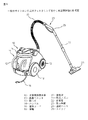
図8には、一般のサイクロン方式のフィルタリングを行う真空掃除機を示している。図示のように、真空掃除機は、室内の空気を吸い込む吸い込み手段が組み込まれた本体10と、前記本体10の内部と連通するように連結されるフレキシブルな連結ホース24と、前記連結ホース24の端部に連通するように設けられ、長さの調節が可能な延長管22と、前記本体10で発生する吸引力によって、異物質を含む空気が床面から流入される吸込みノズル21とを備えている。
FIG. 8 shows a vacuum cleaner that performs general cyclonic filtering. As shown in the figure, the vacuum cleaner includes a
そして、前記本体10には、後方に着脱可能に集塵ユニット11が設けられている。前記集塵ユニット11では、吸込みノズル21を介して吸い込まれる異物質を含む空気を流入させ、内部でサイクロン方式の集塵を行っている。また、前記本体10の側面には、前記集塵ユニット11の内部で異物質のフィルタリングされた空気が外部に排出される排気部19が設けられている。
The
前記本体10の底面には、本体を移動させるための一対の車輪18が回動自在に設けられている。かつ、前記本体10の一側には、真空掃除機に電源を供給するための電源コード16が設けられるが、この電源コード16は、本体の内部のコードリール(図示せず)に巻き付けられ、内部に収納できるように設けられている。
また、前記集塵ユニット11には、本体10の後方で着脱するときに、使用者が握るための取っ手12が設けられている。かつ、前記本体10の上面には、真空掃除機を移動させるときに使用者が握るためのハンドル14が設けられている。
A pair of
Further, the
このような構成となる真空掃除機本体10が駆動されると、本体の内部で真空状態の吸引力が発生し、この吸引力が連結ホース24及び延長管22を介して吸込みノズル21に伝達される。ここで、前記真空掃除機の吸引力は、延長管22の上部に連結される取っ手部23に設けられたスイッチ25で調節することができる。
また、前記吸引力によって、掃除する床面の異物質を含む空気は、前記吸込みノズル21、延長管22、及び連結ホース24を経て真空掃除機本体10の内部に流入される。次いで、本体の内部では、前記集塵ユニット11の内部に流入され、所定のフィルタを通してフィルタリングされ、外部に別に排出されたりする。
When the vacuum cleaner
In addition, air containing foreign substances on the floor to be cleaned flows into the vacuum cleaner
このような集塵ユニット11は、流路上で生じる吸引力の損失を補うために、より高出力のモータを使用する必要があった。また、集塵ユニット11から集塵された塵芥を排出するために、多段階の分離過程を経なければならないという問題点があった。
Such a
本発明は、上記問題点に鑑みなされたものであり、吸引力を損失することなく、塵埃などのような塵芥を吸い込み、分離/集塵できるサイクロン方式の真空掃除機の集塵ユニットを提供することを目的とする。
また、本発明は、吸引力の損失を抑え、より低出力のモータを使用することが可能となり、騒音や電力の損失を減らし得るサイクロン方式の真空掃除機の集塵ユニットを提供することを目的とする。
また、本発明は、塵芥を排出する過程をより簡単に行うことができるサイクロン方式の真空掃除機の集塵ユニットを提供することを目的とする。
The present invention has been made in view of the above problems, and provides a dust collection unit of a cyclone vacuum cleaner that can suck and separate / collect dust such as dust without losing suction power. For the purpose.
It is another object of the present invention to provide a dust collection unit for a cyclone vacuum cleaner that can reduce loss of suction force, use a motor with a lower output, and reduce noise and power loss. And
Another object of the present invention is to provide a dust collection unit for a cyclone vacuum cleaner that can more easily perform the process of discharging dust.
上記の目的を達成するため、本発明の実施の形態による真空掃除機の集塵ユニットは、外周面に設けられた空気流入口と、一側に設けられた空気排出口を有する塵芥分離チャンバーと、前記塵芥分離チャンバー内に設けられ、サイクロン方式で塵芥を分離する主集塵室と、前記主集塵室の側面に設けられる補助集塵室と、前記主集塵室を水平に仕切る仕切り板と、前記塵芥分離チャンバーの下部で開閉可能に取り付けられる下部カバーとを備えることを特徴とする。 In order to achieve the above object, a dust collecting unit of a vacuum cleaner according to an embodiment of the present invention includes an air inlet provided on the outer peripheral surface, and a dust separation chamber having an air outlet provided on one side. A main dust collection chamber provided in the dust separation chamber for separating dust in a cyclone manner, an auxiliary dust collection chamber provided on a side surface of the main dust collection chamber, and a partition plate for horizontally partitioning the main dust collection chamber And a lower cover attached to the lower part of the dust separation chamber so as to be openable and closable.
また、本発明の実施の形態による真空掃除機の集塵ユニットは、外周面に設けられた空気流入口と、一側に設けられた空気排出口を有する塵芥分離チャンバーと、前記塵芥分離チャンバー内に設けられ、サイクロン方式で塵芥を分離する主集塵室と、前記主集塵室の側面に設けられる補助集塵室と、前記主集塵室を水平に仕切り、少なくとも一つの開口部を有する仕切り板とを備えることを特徴とする。 The dust collection unit of the vacuum cleaner according to the embodiment of the present invention includes an air inlet provided on the outer peripheral surface, a dust separation chamber having an air discharge port provided on one side, and the dust separation chamber. A main dust collection chamber for separating dust in a cyclone method, an auxiliary dust collection chamber provided on a side surface of the main dust collection chamber, and horizontally partitioning the main dust collection chamber, and having at least one opening. And a partition plate.
また、本発明の実施の形態による真空掃除機の集塵ユニットは、外周面の接線方向に設けられた空気流入口と、一側に設けられた空気排出口を有する塵芥分離チャンバーと、前記塵芥分離チャンバー内に設けられ、サイクロン方式で塵芥を分離する主集塵室と、前記主集塵室の側面に設けられる補助集塵室と、前記主集塵室を水平に仕切る仕切り板と、前記主集塵室から補助集塵室に空気を流入させるために、前記主集塵室の上側の一部に設けられた連通孔とを備えることを特徴とする。 The dust collection unit of the vacuum cleaner according to the embodiment of the present invention includes an air inlet provided in a tangential direction of an outer peripheral surface, a dust separation chamber having an air outlet provided on one side, and the dust A main dust collection chamber provided in the separation chamber for separating dust in a cyclone manner; an auxiliary dust collection chamber provided on a side surface of the main dust collection chamber; a partition plate for horizontally partitioning the main dust collection chamber; In order to allow air to flow from the main dust collection chamber into the auxiliary dust collection chamber, a communication hole provided in a part of the upper side of the main dust collection chamber is provided.
また、本発明の実施の形態による真空掃除機の集塵ユニットは、外周面に設けられた空気流入口と、一側に設けられた空気排出口を有する塵芥分離チャンバーと、前記塵芥分離チャンバー内に設けられ、サイクロン方式で塵芥を分離する主集塵室と、前記主集塵室の側面に設けられる補助集塵室と、前記主集塵室を水平に仕切る仕切り板と、前記主集塵室と補助集塵室との間で空気が流通するように前記主集塵室の下側の一部に設けられた連通孔を備えることを特徴とする。 The dust collection unit of the vacuum cleaner according to the embodiment of the present invention includes an air inlet provided on the outer peripheral surface, a dust separation chamber having an air discharge port provided on one side, and the dust separation chamber. A main dust collecting chamber for separating dust in a cyclone method, an auxiliary dust collecting chamber provided on a side surface of the main dust collecting chamber, a partition plate for horizontally partitioning the main dust collecting chamber, and the main dust collecting chamber. A communication hole is provided in a part of the lower side of the main dust collection chamber so that air flows between the chamber and the auxiliary dust collection chamber.
このような本発明による真空掃除機の集塵ユニットによれば、吸引力の損失を極力抑えることにより、安価なモータを用いて生産コストを低減することができる。また、集塵された塵埃を容易に排出することが可能となり、使用者の便宜を図ることができる。
また、本発明によれば、吸い込まれる吸気の量や塵芥の捕集効率を向上させ、少ない容量のモータを用いることが可能となり、安価な真空掃除機を提供することができる。
また、掃除機に捕集された塵芥を容易に除去することができるため、真空掃除の使用上の便宜性をより向上させる効果を有する。
また、主集塵室と補助集塵室とを共に設けることにより、塵芥の捕集効率をより向上させ、主集塵室に捕集されない微細な塵埃まで完全に除去することができる。
According to such a dust collecting unit of the vacuum cleaner according to the present invention, it is possible to reduce the production cost by using an inexpensive motor by suppressing loss of suction force as much as possible. In addition, the collected dust can be easily discharged, which can be convenient for the user.
Further, according to the present invention, the amount of sucked air and the collection efficiency of dust can be improved, a motor with a small capacity can be used, and an inexpensive vacuum cleaner can be provided.
Moreover, since the dust collected by the vacuum cleaner can be easily removed, it has the effect of further improving convenience in use of vacuum cleaning.
Further, by providing both the main dust collection chamber and the auxiliary dust collection chamber, it is possible to further improve dust collection efficiency and completely remove even fine dust that is not collected in the main dust collection chamber.
以下、本発明の好ましい実施の形態を、添付図面に基づいて詳しく説明する。
ただ、説明の便宜上、従来と同じ機能を有する構成要素については、同一の番号を付して説明する。
図1は、本発明に係るサイクロン方式の真空掃除機の集塵ユニットの正面斜視図であり、図2は、本発明に係るサイクロン方式の真空掃除機の集塵ユニットの背面斜視図であり、図3は、本発明に係るサイクロン方式の真空掃除機の集塵ユニットの分解斜視図であり、図4は、図3のB−B′線断面図である。
Hereinafter, preferred embodiments of the present invention will be described in detail with reference to the accompanying drawings.
However, for convenience of explanation, components having the same functions as those in the past will be described with the same numbers.
FIG. 1 is a front perspective view of a dust collection unit of a cyclone vacuum cleaner according to the present invention, and FIG. 2 is a rear perspective view of the dust collection unit of a cyclone vacuum cleaner according to the present invention. FIG. 3 is an exploded perspective view of the dust collection unit of the cyclone vacuum cleaner according to the present invention, and FIG. 4 is a cross-sectional view taken along line BB ′ of FIG.
図1乃至図4を参照して説明すると、本発明に係る真空掃除機は、集塵ユニット11の上端部を覆って内部部品を保護し、吸い込まれる空気が抜けていかないように密閉するカバー30と、前記カバー30のほぼ中心に開口された流出口31を中心として下側に設けられるフィルタ40と、前記カバー30の下側に取り付けられる集塵ケーシング80とを備えている。
詳しくは、前記カバー30のほぼ中心には、集塵ケーシング80に吸い込まれた空気から塵芥が分離されてきれいになった空気が排出される流出口31が設けられ、前記流出口31の下側には、微細なフィルタ構造となり、微細な塵埃をフィルタリングするフィルタ40を備えている。
Referring to FIGS. 1 to 4, the vacuum cleaner according to the present invention covers the upper end portion of the
Specifically, an
前記フィルタ40は、円柱状であり、外周に微細なフィルタリング構造が設けられている。集塵ケーシング80内の空気は、フィルタ40を介して塵埃がフィルタリングされた後、前記流出口31を介して外部に排出される。
The
また、前記集塵ケーシング80は、真空掃除機本体で吸い込まれる空気が集塵ユニット11に流入される流入経路としての流入口71と、該流入口71を通して吸い込まれる空気が遠心力により渦巻き、自重で落下する塵芥を空気から分離するための円筒状の塵芥分離チャンバー70と、前記塵芥分離チャンバー70の下側に設けられ、自重で落下した塵芥が溜まる主集塵室50とを備えている。また、主集塵室50を水平に仕切るために、塵芥分離チャンバー70に設けられる仕切り板73を備え、前記仕切り板73の外周には、一部が開口され、塵芥分離チャンバー70を渦巻く塵芥が主集塵室50に落下するようにする開口部74が設けられる。
The
前記仕切り板73は、塵芥分離チャンバー70の内部に一体に固定されるように設けたり、別の固定手段で開閉可能に設けてもよい。
自重が軽すぎて前記開口部74を介して落下できない塵芥もある。このような軽すぎる塵芥を分離するために、前記塵芥分離チャンバー70の上側面の開口される上部連通孔72と、前記主集塵室50の側面に設けられる補助集塵室60を備えている。
また、前記主集塵室50と補助集塵室60とを区切るための区切り壁75と、前記区切り壁75を貫通して前記主集塵室50と補助集塵室60とがお互いに連通するようにし、塵芥の捕集効率を向上するための下部連通孔52をさらに設けている。
The
Some dusts are too light to fall through the opening 74. In order to separate such dust that is too light, an
Further, a
また、前記主集塵室50及び補助集塵室60の下側面を開閉する下部カバー53と、前記下部カバー53が全体として開閉される集塵室の回転中心部81と、下部カバー53が固定され、その位置を保持できるようにする下部カバー固定手段54とを備えている。
また、集塵ケーシング80の外部面には、上下に長く延びており、使用者が握るための取っ手12が設けられている。また、主集塵室50の内部面から内側に突出され、上下に長く延び、吸引力を向上するために、主集塵室50の内部で塵埃が渦巻かないようにする止まり板51が設けられている。
Further, a
In addition, a
また、前記流入口71は、吸い込まれた空気が渦巻き、吸い込まれた空気の遠心力により塵芥が分離されるように、前記塵芥分離チャンバー70の接線方向に設けられている。
また、前記カバー30には、カバー30を集塵ユニット11から取り外すときに、作業者の便宜を図るため、取っ手の構造としてカバー突出部32が設けられている。
The
Further, the
詳しくは、前記主集塵室50の前方、即ち、取っ手12の反対側には、主集塵室50の微細な塵埃を集塵させるための補助集塵室60が設けられている。前記補助集塵室60は、主集塵室50の一側の壁の区切り壁75を挟んでさらに他の一つの空間として設けられる。主集塵室50内の上部で継続して回転する微細な塵埃は、上部連通孔72を経て前記補助集塵室60に集塵される。前記区切り壁75により主集塵室50と補助集塵室60との間で与えられるそれぞれ異なる空気流動による影響を減らすことができる。
ただ、前記主集塵室50と補助集塵室60とをお互いに連通させる上部連通孔72と下部連通孔52とが前記主集塵室50の区切り壁75に設けられる。
Specifically, an auxiliary
However, an
前記上部連通孔72は、流入された塵芥のうち、重量が軽すぎて自由落下できず、塵芥分離チャンバー70内で渦巻き続ける微細な塵埃を補助集塵室60に移送させるために設けられている。この上部連通孔72は、塵芥分離チャンバー70の上部壁に沿って渦巻く塵埃を補助集塵室60に流入させるため、区切り壁75の上部に形成させることが好ましい。
また、下部連通孔52は、区切り壁75の下部に設けられており、主集塵室50の内部に溜まった塵芥が前記補助集塵室60の内部にも一部収容されるようになっている。
The
The
詳しくは、集塵ケーシング80の主集塵室50に主として塵芥が捕集され、補助集塵室60には、微細な塵埃が集塵されるため、主集塵室50に塵芥が一杯になっても、補助集塵室60は、未だ空いていることもある。この場合、主集塵室50に塵芥が一杯になる場合、一部の塵芥を補助集塵室60に移動させるために、下部連通孔52が設けられている。
このように、主集塵室50に塵芥が一杯になる場合、主集塵室の塵芥は、自然に下部連通孔52を介して補助集塵室60に移動することが可能となり、集塵ケーシング80の集塵空間をより効率的に使用することが可能となる。
Specifically, since dust is mainly collected in the main
In this way, when the main
また、下部連通孔52の形成により、流入口71から流入された空気の一部は、上部連通孔72から下部連通孔52を経て主集塵室50の内部に流動されるため、流路が断絶することなく、連続することになり、吸引力の損失を防止することができる。もし、下部連通孔52が設けられていないと、上部連通孔72を経た空気は、補助集塵室60の内部で渦巻き流が形成され、形成された渦巻き流分だけの空気流動が行われず、吸引力の損失が発生する。
Further, due to the formation of the
前記流出口31の下部には、円筒状のフィルタ40が設けられる。このフィルタ40は、円筒状の内部が前記流出口31と連通するようにカバー30の下面に着脱可能に設けられている。塵芥が濾過された空気は、前記フィルタ40を経てよりきれいな空気に浄化され、本体の外部に排出される。
A
図4を参照して、主集塵室50の境界面をなす塵芥分離チャンバー70の内周面に、内側に突設される少なくとも一つの止まり板511、512、513、514が設けられている。また、補助集塵室60と主集塵室50とを区切る区切り壁75と、前記区切り壁75を貫通する下部連通孔52がさらに設けられている。
Referring to FIG. 4, at least one
前記止まり板511、512、513、514は、主集塵室50の内部にまで形成される渦巻き流が止まるようにし、塵芥が止まり板511、512、513、514に溜まるようにしている。つまり、塵芥が主集塵室50の内部で渦巻き続けることなく、主集塵室50の内部で溜まるようにすることにより、捕集された塵芥がさらに抜け出すことを防止する。
図4においては、矢印は、空気の流動方向を説明しており、止まり板511、512、513、514に止まり、それ以上移動しない塵芥が溜まることを模式的に示している。
The
In FIG. 4, the arrows describe the flow direction of air, and schematically show that dust that stops at the
図5は、本発明に係るサイクロン方式の真空掃除機の作動状態を説明する図である。
図5を参照して、集塵ケーシング80の内部の集塵作用について説明する。真空掃除機が駆動すると、従来の技術においても述べられた吸込みノズルや延長管、吸い込みホースを介して塵芥を含む空気が吸い込まれ、集塵ケーシング80の流入口71を介して流入される。次いで、前記流入口71を通過した塵芥を含む空気は、円筒状の塵芥分離チャンバー70の内部の壁面に沿って渦巻き流を形成するが、このとき、比較的重い塵芥は、下部に下降し、仕切り板73の外周面に設けられた開口部74を介して主集塵室50に移動しながら捕集される。
FIG. 5 is a diagram for explaining the operating state of the cyclone vacuum cleaner according to the present invention.
With reference to FIG. 5, the dust collecting action inside the
また、自重が軽すぎて塵芥分離チャンバー70の壁面に沿って渦巻きながら、自由落下することができない微細な塵埃は、区切り壁75の上部連通孔72を介して落下し、補助集塵室60に捕集される。このとき、空気は、上部連通孔72から下部連通孔52を経てさらに主集塵室50に移動し、フィルタ40を経て外部に排出される。
また、主集塵室50に溜まった塵芥の一部は、前記下部連通孔52を介して補助集塵室60に移動するため、主集塵室50の内部に一定量以上の塵芥が溜まっても真空掃除機に吸い込まれる空気の吸い込み効率には差支えがない。
図5において、矢印は、集塵ユニット内に吸い込まれる空気の循環経路を詳しく説明する。
In addition, fine dust that is too light to swirl along the wall surface of the
Further, a part of the dust collected in the main
In FIG. 5, the arrows describe in detail the circulation path of the air sucked into the dust collection unit.
図6は、図3のA−A′線断面図であり、詳しくは、下部カバー固定手段の断面図である。
図6を参照して説明すると、下部カバー固定手段54は、塵芥分離チャンバー70の外部面から突設される突出部82と、前記突出部82の突出端部に該当する高さに設けられる可動部材83と、前記可動部材83が前記突出部82の縁端で回転可能にヒンジ結合されるようにするヒンジ軸84と、前記可動部材83の最下端に設けられる可動係止具85と、前記下部カバー53の後端部に一体に上側に突設される固定係止具86と、前記可動部材83の上段部の背面と前記集塵ケーシング80の前面との間に設けられる弾性部材87とを備えている。
6 is a cross-sectional view taken along the line AA ′ of FIG. 3, and more specifically, a cross-sectional view of the lower cover fixing means.
Referring to FIG. 6, the lower
上述した構成の動作を説明すると、前記可動係止具85と、前記固定係止具86とが係止された状態では、下部カバー53は開かれない。しかし、可動部材83がヒンジ軸84を中心として回転し、前記可動係止具85と固定係止具86との係合が解除されると、下部カバー53の自重によって前記下部カバー53は、前記集塵室の回転中心部(図3の81参照)を中心として回転し、主集塵室50及び補助集塵室60の下側面が開放されるようになる。
The operation of the above-described configuration will be described. The
主集塵室50及び補助集塵室60の下側面、即ち、下部カバー53が開放されると、主集塵室50及び補助集塵室60の内部に捕集されていた塵芥が自重によって外部に排出されるため、主集塵室50、補助集塵室60の内部から容易に除去することができる。
掃除機の使用者は、このような塵芥の排出作業のためには、前記可動部材83の上側部を奥側に押すだけでよい。また、前記可動部材83の移動は、前記弾性部材87の復元力によって可動部材83が押されることになり、元の位置に復元することができる。
When the lower surface of the main
The user of the vacuum cleaner only needs to push the upper side of the
前記弾性部材87の位置を固定するために、可動部材83の奥面や集塵ケーシング80の前面には、それぞれ第1の支持具88及び第2の支持具89が設けられ、その外周に弾性部材87が嵌合されており、弾性部材87が抜けられないようになっている。
このため、前記下部カバー53、即ち、主集塵室50や補助集塵室60の全ての下側面を覆い、前記下部カバー53が下部カバー固定手段54の開放動作によって開放されると、主集塵室50及び補助集塵室60の内部に捕集されている塵埃などのような塵芥が自重によってすべて下降するようにしている。
In order to fix the position of the
Therefore, when the
図7は、前記下部カバー固定手段54が開放される状態を説明する図であり、図示のように、集塵室の下側が開放される場合には、主集塵室50及び補助集塵室60の内部に捕集されている塵芥が簡単に排出されることになり、この動作中には、作業者が取っ手12を握っており、その位置を安定して保持することができる。
FIG. 7 is a view for explaining a state in which the lower cover fixing means 54 is opened. As shown in the figure, when the lower side of the dust collection chamber is opened, the main
以上のように、上記実施の形態を参照して詳細に説明され図示されたが、本発明は、これに限定されるものでなく、このような本発明の基本的な技術的思想を逸脱しない範囲内で、当業界の通常の知識を有する者にとっては、他の多くの変更が可能であろう。また、本発明は、添付の特許請求の範囲により解釈されるべきであることは言うまでもない。 As described above, although described and illustrated in detail with reference to the above-described embodiment, the present invention is not limited to this and does not depart from the basic technical idea of the present invention. Many other modifications will be possible to those skilled in the art within the scope. Needless to say, the present invention should be construed in accordance with the appended claims.
12…取っ手
30…カバー
31…流出口
32…カバー突出部
40…フィルタ
50…主集塵室
52…下部連通孔
53…下部カバー
54…下部カバー固定手段
60…補助集塵室
70…塵芥分離チャンバー
71…流入口
72…上部連通孔
73…仕切り板
DESCRIPTION OF
Claims (9)
前記空気流入口を通って前記集塵ケーシング内へ吸い込まれた空気から塵芥を分離する塵芥分離チャンバーと、
前記塵芥分離チャンバー内で下側に設けられ、サイクロン方式により分離され落下する塵芥を溜める主集塵室と、
前記集塵ケーシングの一側壁の外側に設けられ、前記塵芥分離チャンバーおよび前記主集塵室にそれぞれ連通し、前記主集塵室に落下しないで前記塵芥分離チャンバーから流出する微細な塵芥を集める補助集塵室と、
前記塵芥分離チャンバーの上面を開閉するように取り付けられ、かつ空気を排出する開口部が中央部に設けられたカバーとを備えることを特徴とする真空掃除機の集塵ユニット。 A dust having an air inlet formed in a tangential direction with respect to the outer peripheral surface of the side wall of the dust collecting casing of the vacuum cleaner, and separating the dust from the air sucked into the dust collecting casing through the air inlet. A separation chamber;
A main dust collection chamber which is provided at the lower side in the dust separation chamber, and stores dust that is separated and dropped by a cyclone method;
An auxiliary device provided outside one side wall of the dust collection casing , communicates with the dust separation chamber and the main dust collection chamber, and collects fine dust flowing out of the dust separation chamber without falling into the main dust collection chamber. A dust collection chamber;
A dust collection unit of a vacuum cleaner, comprising: a cover attached to open and close the upper surface of the dust separation chamber, and a cover provided with an opening for discharging air at a central portion.
Applications Claiming Priority (1)
| Application Number | Priority Date | Filing Date | Title |
|---|---|---|---|
| KR1020030029630A KR100587099B1 (en) | 2003-05-10 | 2003-05-10 | Dust removing unit of cyclone cleaner |
Publications (3)
| Publication Number | Publication Date |
|---|---|
| JP2004329880A JP2004329880A (en) | 2004-11-25 |
| JP2004329880A5 JP2004329880A5 (en) | 2005-06-02 |
| JP4084323B2 true JP4084323B2 (en) | 2008-04-30 |
Family
ID=36969232
Family Applications (1)
| Application Number | Title | Priority Date | Filing Date |
|---|---|---|---|
| JP2004065932A Expired - Fee Related JP4084323B2 (en) | 2003-05-10 | 2004-03-09 | Dust collection unit of vacuum cleaner |
Country Status (6)
| Country | Link |
|---|---|
| US (2) | US7086119B2 (en) |
| EP (1) | EP1477099B1 (en) |
| JP (1) | JP4084323B2 (en) |
| KR (1) | KR100587099B1 (en) |
| DE (1) | DE602004022481D1 (en) |
| RU (1) | RU2260367C1 (en) |
Families Citing this family (47)
| Publication number | Priority date | Publication date | Assignee | Title |
|---|---|---|---|---|
| US7343643B2 (en) * | 2003-03-17 | 2008-03-18 | Panasonic Corporation Of North America | Selective bag or bagless cleaning system |
| US7235121B2 (en) * | 2003-12-26 | 2007-06-26 | West Timothy J | Externally removable vacuum cleaner filter apparatus |
| GB0402847D0 (en) * | 2004-02-10 | 2004-03-17 | Black & Decker Inc | Filter assembly for vacuum cleaner and vacuum cleaner incorporating such assembly |
| US20050198769A1 (en) * | 2004-03-11 | 2005-09-15 | Lg Electronics Inc. | Vacuum cleaner |
| US7640623B2 (en) * | 2004-03-11 | 2010-01-05 | Lg Electronics Inc. | Vacuum cleaner |
| US7669282B2 (en) * | 2004-03-11 | 2010-03-02 | Lg Electronics Inc. | Vacuum cleaner |
| US7779507B2 (en) * | 2004-03-11 | 2010-08-24 | Lg Electronics Inc. | Vacuum cleaner |
| US20050198771A1 (en) * | 2004-03-11 | 2005-09-15 | Lg Electronics Inc. | Vacuum cleaner |
| US7779506B2 (en) * | 2004-03-11 | 2010-08-24 | Lg Electronics Inc. | Vacuum cleaner |
| KR100554238B1 (en) * | 2004-11-15 | 2006-02-22 | 삼성광주전자 주식회사 | A cyclone dust-separating apparatus |
| KR101143807B1 (en) * | 2005-04-11 | 2012-05-11 | 엘지전자 주식회사 | Dust and dirt collecting unit for vacuum cleaner |
| US20070144116A1 (en) * | 2005-12-23 | 2007-06-28 | Samsung Electronics Co., Ltd. | Cyclonic cleaner |
| EP1949967B1 (en) * | 2007-01-24 | 2015-03-25 | LG Electronics Inc. | Dust collector of a vacuum cleaner |
| KR100838885B1 (en) * | 2007-01-24 | 2008-06-16 | 엘지전자 주식회사 | Vacuum cleaner |
| US7996957B2 (en) | 2007-03-02 | 2011-08-16 | Kah Jr Carl L C | Centrifugal dirt separation configurations for household-type and shop-type vacuum cleaners |
| US9119511B2 (en) | 2007-03-02 | 2015-09-01 | Carl L. C. Kah, Jr. | Centrifugal dirt separation configurations for household-type and shop-type vacuum cleaners |
| MX2010000383A (en) * | 2007-07-09 | 2010-04-22 | Johnson & Son Inc S C | Handheld portable devices for touchless particulate matter removal. |
| KR100842966B1 (en) * | 2007-07-19 | 2008-07-01 | 엘지전자 주식회사 | Dust collecting apparatus of vaccum cleaner |
| WO2009076773A1 (en) * | 2007-12-19 | 2009-06-25 | Gbd Corp. | Cyclone separator assembly and surface cleaning apparatus having same |
| US7941895B2 (en) * | 2007-12-19 | 2011-05-17 | G.B.D. Corp. | Configuration of a cyclone assembly and surface cleaning apparatus having same |
| US8191203B2 (en) * | 2008-01-16 | 2012-06-05 | Samsung Electronics Co., Ltd. | Dust receptacle and vacuum cleaner having the same |
| KR20090099850A (en) * | 2008-03-18 | 2009-09-23 | 삼성광주전자 주식회사 | Dust case and cyclone dust collecting device having the same |
| KR101524791B1 (en) * | 2008-11-07 | 2015-06-03 | 삼성전자주식회사 | Cyclone dust collecting appapatus and cleaner having the same |
| US8661609B2 (en) | 2008-12-03 | 2014-03-04 | S.C. Johnson & Son, Inc. | Portable devices for touchless particulate matter removal |
| US9211044B2 (en) | 2011-03-04 | 2015-12-15 | Omachron Intellectual Property Inc. | Compact surface cleaning apparatus |
| DE102009035619A1 (en) * | 2009-07-31 | 2011-04-21 | BSH Bosch und Siemens Hausgeräte GmbH | Vacuum cleaner with Staubabscheideeinheit |
| US20110056045A1 (en) * | 2009-09-10 | 2011-03-10 | Electrolux Home Care Products, Inc. | Dirt Cup Latch Mechanism |
| US8875340B2 (en) | 2010-03-12 | 2014-11-04 | G.B.D. Corp. | Surface cleaning apparatus with enhanced operability |
| US8997309B2 (en) | 2012-03-02 | 2015-04-07 | G.B.D. Corp. | Surface cleaning apparatus |
| WO2012165034A1 (en) * | 2011-06-02 | 2012-12-06 | 三菱電機株式会社 | Electric vacuum cleaner |
| TWI581747B (en) * | 2013-01-30 | 2017-05-11 | 三菱電機股份有限公司 | Electric vacuum cleaner |
| JP5935708B2 (en) * | 2013-01-30 | 2016-06-15 | 三菱電機株式会社 | Electric vacuum cleaner |
| US9326652B2 (en) | 2013-02-28 | 2016-05-03 | Omachron Intellectual Property Inc. | Surface cleaning apparatus |
| US20140237764A1 (en) | 2013-02-28 | 2014-08-28 | G.B.D. Corp. | Cyclone such as for use in a surface cleaning apparatus |
| US9227151B2 (en) | 2013-02-28 | 2016-01-05 | Omachron Intellectual Property Inc. | Cyclone such as for use in a surface cleaning apparatus |
| US9227201B2 (en) | 2013-02-28 | 2016-01-05 | Omachron Intellectual Property Inc. | Cyclone such as for use in a surface cleaning apparatus |
| US9451855B2 (en) | 2013-02-28 | 2016-09-27 | Omachron Intellectual Property Inc. | Surface cleaning apparatus |
| US9820621B2 (en) | 2013-02-28 | 2017-11-21 | Omachron Intellectual Property Inc. | Surface cleaning apparatus |
| US9295995B2 (en) | 2013-02-28 | 2016-03-29 | Omachron Intellectual Property Inc. | Cyclone such as for use in a surface cleaning apparatus |
| US9238235B2 (en) | 2013-02-28 | 2016-01-19 | Omachron Intellectual Property Inc. | Cyclone such as for use in a surface cleaning apparatus |
| FR3007269B1 (en) * | 2013-06-21 | 2015-07-03 | Seb Sa | DEVICE FOR RECOVERING DUST FROM A VACUUM CLEANER |
| US10631697B2 (en) | 2014-02-14 | 2020-04-28 | Techtronic Industries Co. Ltd. | Separator configuration |
| CN110123203A (en) | 2014-10-22 | 2019-08-16 | 创科实业有限公司 | Vacuum cleaner with cyclone separator |
| EP3209175B1 (en) | 2014-10-22 | 2023-01-04 | Techtronic Industries Co. Ltd. | Handheld vacuum cleaner |
| US9775483B2 (en) | 2014-10-22 | 2017-10-03 | Techtronic Industries Co. Ltd. | Vacuum cleaner having cyclonic separator |
| JP5933099B2 (en) * | 2015-11-20 | 2016-06-08 | シャープ株式会社 | Dust collector and self-propelled vacuum cleaner provided with the same |
| US11246462B2 (en) * | 2019-11-18 | 2022-02-15 | Omachron Intellectual Property Inc. | Multi-inlet cyclone |
Family Cites Families (37)
| Publication number | Priority date | Publication date | Assignee | Title |
|---|---|---|---|---|
| US2432757A (en) * | 1945-06-13 | 1947-12-16 | Beaumont Birch Company | Ash and dust separator |
| US3856488A (en) | 1972-09-05 | 1974-12-24 | Mitsubishi Electric Corp | Electric vacuum cleaner |
| NL7613475A (en) * | 1976-12-03 | 1978-06-06 | Philips Nv | VACUUM CLEANER. |
| JPS56114755A (en) | 1980-02-15 | 1981-09-09 | Yokogawa Hokushin Electric Corp | Detecting apparatus of ignition and flame extinction of gas analyzer |
| CA1236922A (en) | 1983-11-30 | 1988-05-17 | Paul Mermelstein | Method and apparatus for coding digital signals |
| JPH074654B2 (en) | 1986-12-08 | 1995-01-25 | 扶桑軽合金株式会社 | Product removal method in die casting |
| CA2034694C (en) | 1990-02-01 | 2003-04-08 | Antonio Gutierrez | Ethylene alpha-olefin polymer substituted mannich base useful as multifunctional viscosity index improver for oleaginous composition |
| RU2050825C1 (en) | 1993-04-20 | 1995-12-27 | Акционерное общество "Уралэлектротяжмаш" | Dust collector for the vacuum cleaner |
| US6003196A (en) * | 1998-01-09 | 1999-12-21 | Royal Appliance Mfg. Co. | Upright vacuum cleaner with cyclonic airflow |
| US6168641B1 (en) | 1998-06-26 | 2001-01-02 | Akteibolaget Electrolux | Cyclone separator device for a vacuum cleaner |
| US7096531B2 (en) | 1998-12-01 | 2006-08-29 | The Procter & Gamble Company | Cleaning implement for cleaning a surface |
| GB2344745B (en) | 1998-12-18 | 2002-06-05 | Notetry Ltd | Vacuum cleaner |
| US6334234B1 (en) * | 1999-01-08 | 2002-01-01 | Fantom Technologies Inc. | Cleaner head for a vacuum cleaner |
| US6228260B1 (en) * | 1999-07-27 | 2001-05-08 | G. B. D. Corp. | Apparatus for separating particles from a cyclonic fluid flow |
| US6440197B1 (en) * | 1999-07-27 | 2002-08-27 | G.B.D. Corp. | Apparatus and method separating particles from a cyclonic fluid flow including an apertured particle separation member within a cyclonic flow region |
| GB9930332D0 (en) | 1999-12-22 | 2000-02-09 | Notetry Ltd | Cyclonic separating apparatus |
| US6341404B1 (en) * | 2000-01-13 | 2002-01-29 | Royal Appliance Mfg. Co. | Upright vacuum cleaner with cyclonic airflow pathway |
| US6910245B2 (en) * | 2000-01-14 | 2005-06-28 | White Consolidated Industries, Inc. | Upright vacuum cleaner with cyclonic air path |
| KR100406638B1 (en) | 2000-01-22 | 2003-11-22 | 삼성광주전자 주식회사 | Vacuum cleaner |
| KR100510644B1 (en) * | 2000-02-17 | 2005-08-31 | 엘지전자 주식회사 | cyclone dust collector |
| US6596044B1 (en) | 2000-03-06 | 2003-07-22 | The Hoover Company | Dirt collecting system for a vacuum cleaner |
| GB2363744B (en) * | 2000-06-24 | 2002-11-13 | Samsung Kwangju Electronics Co | Upright type vacuum cleaner having a cyclone-type dust collector |
| WO2002003844A1 (en) | 2000-07-06 | 2002-01-17 | John Herbert North | Improved dust/particle collecting arrangement for cyclone separators |
| KR100437371B1 (en) | 2000-07-26 | 2004-06-25 | 삼성광주전자 주식회사 | Cyclone dust-collecting apparatus for Vaccum Cleaner |
| KR100437364B1 (en) * | 2000-07-26 | 2004-06-25 | 삼성광주전자 주식회사 | Cyclone dust-collecting apparatus for Vaccum Cleaner |
| KR100377015B1 (en) | 2000-08-07 | 2003-03-26 | 삼성광주전자 주식회사 | Cyclone dust-collecting apparatus for Vacuum Cleaner |
| JP3626413B2 (en) | 2000-08-19 | 2005-03-09 | エルジー電子株式会社 | Dust collector and vacuum cleaner using the same |
| KR100377016B1 (en) * | 2000-10-19 | 2003-03-26 | 삼성광주전자 주식회사 | Upright type Vacuum Cleaner |
| KR100437369B1 (en) * | 2001-01-10 | 2004-06-25 | 삼성광주전자 주식회사 | Cyclone dust-collecting apparatus for Vacuum Cleaner |
| US6436160B1 (en) * | 2001-01-11 | 2002-08-20 | Royal Appliance Mfg. Co. | Dirt cup assembly for vacuum cleaner |
| ES2265492T3 (en) | 2001-02-24 | 2007-02-16 | Dyson Technology Limited | A VACUUM CLEANER. |
| US6598263B2 (en) * | 2001-05-09 | 2003-07-29 | The Hoover Company | Vacuum cleaner dirt collecting system with filter cleaning devices |
| US6613129B2 (en) | 2001-06-22 | 2003-09-02 | Euro-Pro Corporation | Cyclone and dust filter vacuum cleaner |
| KR100445470B1 (en) * | 2001-10-09 | 2004-08-21 | 엘지전자 주식회사 | Dirt and dust collecting casing and vacuum cleaner body having the same |
| KR100476423B1 (en) * | 2002-11-15 | 2005-03-17 | 엘지전자 주식회사 | Dust and dirt collecting unit for vacuum cleaner |
| KR100483545B1 (en) * | 2002-11-29 | 2005-04-18 | 삼성광주전자 주식회사 | Cyclone-type dust collecting apparatus for vacuum cleaner |
| US7544224B2 (en) * | 2003-08-05 | 2009-06-09 | Electrolux Home Care Products, Inc. | Cyclonic vacuum cleaner |
-
2003
- 2003-05-10 KR KR1020030029630A patent/KR100587099B1/en active IP Right Grant
-
2004
- 2004-03-01 US US10/788,396 patent/US7086119B2/en not_active Expired - Fee Related
- 2004-03-09 JP JP2004065932A patent/JP4084323B2/en not_active Expired - Fee Related
- 2004-03-23 RU RU2004108669/12A patent/RU2260367C1/en not_active IP Right Cessation
- 2004-03-25 EP EP04007221A patent/EP1477099B1/en not_active Expired - Fee Related
- 2004-03-25 DE DE602004022481T patent/DE602004022481D1/en not_active Expired - Fee Related
-
2006
- 2006-04-25 US US11/410,092 patent/US7409744B2/en not_active Expired - Lifetime
Also Published As
| Publication number | Publication date |
|---|---|
| RU2260367C1 (en) | 2005-09-20 |
| EP1477099A2 (en) | 2004-11-17 |
| US20040177472A1 (en) | 2004-09-16 |
| KR100587099B1 (en) | 2006-06-07 |
| EP1477099B1 (en) | 2009-08-12 |
| US7086119B2 (en) | 2006-08-08 |
| US7409744B2 (en) | 2008-08-12 |
| KR20040096725A (en) | 2004-11-17 |
| EP1477099A3 (en) | 2007-06-20 |
| JP2004329880A (en) | 2004-11-25 |
| DE602004022481D1 (en) | 2009-09-24 |
| US20060200934A1 (en) | 2006-09-14 |
Similar Documents
| Publication | Publication Date | Title |
|---|---|---|
| JP4084323B2 (en) | Dust collection unit of vacuum cleaner | |
| EP1725156B1 (en) | Compact cyclonic bagless vacuum cleaner | |
| JP3626413B2 (en) | Dust collector and vacuum cleaner using the same | |
| KR100640830B1 (en) | Dust collector for vacuum cleaner | |
| RU2226354C2 (en) | Cyclone-type dust collector for vacuum cleaner | |
| RU2328961C1 (en) | Vacuum cleaner (option) | |
| KR100647195B1 (en) | A cyclone dust collecting apparatus | |
| JP3869381B2 (en) | Dust collection unit for vacuum cleaner | |
| US7329295B2 (en) | Light weight bagless vacuum cleaner | |
| KR20020012383A (en) | Cyclone dust-collecting apparatus for Vacuum Cleaner | |
| JP2004358210A (en) | Cyclone dust collecting device for vacuum cleaner | |
| JP2005185838A (en) | Cyclone dust collecting device for use in vacuum cleaner | |
| JP2004113760A (en) | Wet and dry type cleaner | |
| KR20060037989A (en) | Collecting chamber for a vacuum cleaner | |
| KR20070061643A (en) | Dust collector and vacuum cleaner having the same | |
| KR100831082B1 (en) | Vacuum cleaner | |
| JP7153708B2 (en) | Vacuum cleaner and its dust collector | |
| KR100593093B1 (en) | Dust removing unit in vacuum cleaner | |
| JP3841064B2 (en) | Vacuum cleaner | |
| KR100553047B1 (en) | Suction unit for vacuum cleaner | |
| JP2004147953A (en) | Vacuum cleaner | |
| JP2004147951A (en) | Vacuum cleaner | |
| KR100833360B1 (en) | Dust and dirt collecting unit for vacuum cleaner | |
| KR100672533B1 (en) | Vacuum Cleaner | |
| KR100640829B1 (en) | Vacuum cleaner |
Legal Events
| Date | Code | Title | Description |
|---|---|---|---|
| A521 | Written amendment |
Free format text: JAPANESE INTERMEDIATE CODE: A523 Effective date: 20041021 |
|
| A977 | Report on retrieval |
Free format text: JAPANESE INTERMEDIATE CODE: A971007 Effective date: 20061101 |
|
| A131 | Notification of reasons for refusal |
Free format text: JAPANESE INTERMEDIATE CODE: A131 Effective date: 20061121 |
|
| A521 | Written amendment |
Free format text: JAPANESE INTERMEDIATE CODE: A523 Effective date: 20070221 |
|
| A131 | Notification of reasons for refusal |
Free format text: JAPANESE INTERMEDIATE CODE: A131 Effective date: 20070515 |
|
| A601 | Written request for extension of time |
Free format text: JAPANESE INTERMEDIATE CODE: A601 Effective date: 20070814 |
|
| A602 | Written permission of extension of time |
Free format text: JAPANESE INTERMEDIATE CODE: A602 Effective date: 20070817 |
|
| A521 | Written amendment |
Free format text: JAPANESE INTERMEDIATE CODE: A523 Effective date: 20071114 |
|
| TRDD | Decision of grant or rejection written | ||
| A01 | Written decision to grant a patent or to grant a registration (utility model) |
Free format text: JAPANESE INTERMEDIATE CODE: A01 Effective date: 20080115 |
|
| A61 | First payment of annual fees (during grant procedure) |
Free format text: JAPANESE INTERMEDIATE CODE: A61 Effective date: 20080214 |
|
| R150 | Certificate of patent or registration of utility model |
Free format text: JAPANESE INTERMEDIATE CODE: R150 |
|
| FPAY | Renewal fee payment (event date is renewal date of database) |
Free format text: PAYMENT UNTIL: 20110222 Year of fee payment: 3 |
|
| FPAY | Renewal fee payment (event date is renewal date of database) |
Free format text: PAYMENT UNTIL: 20110222 Year of fee payment: 3 |
|
| FPAY | Renewal fee payment (event date is renewal date of database) |
Free format text: PAYMENT UNTIL: 20120222 Year of fee payment: 4 |
|
| FPAY | Renewal fee payment (event date is renewal date of database) |
Free format text: PAYMENT UNTIL: 20130222 Year of fee payment: 5 |
|
| FPAY | Renewal fee payment (event date is renewal date of database) |
Free format text: PAYMENT UNTIL: 20140222 Year of fee payment: 6 |
|
| R250 | Receipt of annual fees |
Free format text: JAPANESE INTERMEDIATE CODE: R250 |
|
| LAPS | Cancellation because of no payment of annual fees |