EP3609317B1 - Rationale bienenstockstruktur - Google Patents
Rationale bienenstockstruktur Download PDFInfo
- Publication number
- EP3609317B1 EP3609317B1 EP18717363.8A EP18717363A EP3609317B1 EP 3609317 B1 EP3609317 B1 EP 3609317B1 EP 18717363 A EP18717363 A EP 18717363A EP 3609317 B1 EP3609317 B1 EP 3609317B1
- Authority
- EP
- European Patent Office
- Prior art keywords
- comb
- hive
- rational
- brood
- lateral wall
- Prior art date
- Legal status (The legal status is an assumption and is not a legal conclusion. Google has not performed a legal analysis and makes no representation as to the accuracy of the status listed.)
- Active
Links
Images









Classifications
-
- A—HUMAN NECESSITIES
- A01—AGRICULTURE; FORESTRY; ANIMAL HUSBANDRY; HUNTING; TRAPPING; FISHING
- A01K—ANIMAL HUSBANDRY; AVICULTURE; APICULTURE; PISCICULTURE; FISHING; REARING OR BREEDING ANIMALS, NOT OTHERWISE PROVIDED FOR; NEW BREEDS OF ANIMALS
- A01K51/00—Appliances for treating beehives or parts thereof, e.g. for cleaning or disinfecting
-
- A—HUMAN NECESSITIES
- A01—AGRICULTURE; FORESTRY; ANIMAL HUSBANDRY; HUNTING; TRAPPING; FISHING
- A01K—ANIMAL HUSBANDRY; AVICULTURE; APICULTURE; PISCICULTURE; FISHING; REARING OR BREEDING ANIMALS, NOT OTHERWISE PROVIDED FOR; NEW BREEDS OF ANIMALS
- A01K59/00—Honey collection
-
- A—HUMAN NECESSITIES
- A01—AGRICULTURE; FORESTRY; ANIMAL HUSBANDRY; HUNTING; TRAPPING; FISHING
- A01K—ANIMAL HUSBANDRY; AVICULTURE; APICULTURE; PISCICULTURE; FISHING; REARING OR BREEDING ANIMALS, NOT OTHERWISE PROVIDED FOR; NEW BREEDS OF ANIMALS
- A01K47/00—Beehives
Definitions
- the present invention relates to a hive structure, in particular an improved rational hive architecture to develop a bee colony.
- the hive structure allows a new interactions between the hive and the bee colony and the results are bees performing better than bees living in standard hives, including the quality of each bee and the whole colony and including the natural decreasing of the parasite growing ratio and bee pathologies.
- Honeybees are social insects living in wax nests dedicated to the production and storage of honey and pollen.
- Western honeybee is the best-known honeybee, which has been used for honey production and crop pollination, according to its biological life cycle.
- the honeybee managed by humans faces the increasing difficulties due to the worldwide increase of honeybee mortality.
- Honeybee colony instinctively chooses natural nests to live in and reproduce; natural nest structure is generally a cavity where the honeybees adapt building wax combs.
- Hives are human-made artificial nests used for beekeeping purposes. Hives can be subdivided in natural ones like e.g. skeps or hollow trees, and into rational hives.
- a top bar hive in Scotland will probably benefit from some kind of winter insulation more than, for example, a double walled WBC in the South of England.
- insulating the hive may affect the humidity " .
- the bee temperature dependency is well known to have biological effects (e.g. queen laying ratio and incubation timing).
- every scientific papers and community artisans neglect the relation between the hive performance and the colony development.
- the method to select resistant bees includes the human made selection of bee colonies able to exhibit some resistant mechanism against Varroa mite, e.g. grooming, hygienic, or a selection starting from few survived bees coming from a large number of colonies.
- US Patent Document 5,162,014 A discloses a hive structure which conforms to the preamble of claim 1. However, this document considers the use of magnetic fields in the control of the mite.
- the rational hive structure 1 comprises a nest comb box 2 delimiting a brood chamber for bees.
- the brood chamber is the nursery area where brood at various stages of development - eggs, larvae, and pupae - is located.
- the nest comb box is generally in the shape of a box defining at its interior the brood chamber.
- the nest comb box 2 includes a lateral wall 3 delimiting the inner cavity housing the brood chamber.
- the inner cavity has a cross-section in a horizontal plane (see e.g.
- the nest comb box 2 is made therefore of an insulating material, particularly having a low conductivity, such as wood or polyurethane or expanded polymer.
- a low conductivity such as wood or polyurethane or expanded polymer.
- another relevant parameter is the total heat transfer coefficient, which should be lower than 5 W/(m 2 ⁇ K), in particular lower than 3,5 W/(m 2 ⁇ K) and in even more detail less than 0,5 W/(m 2 ⁇ K).
- films, layers, painting or other materials can be used to cover and/or paint the inner or external nest.
- inner natural convection can be improved.
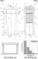
- Figure 1 shows a nest comb box 2 developing vertically: in the upper portion the comb frames 6 are housed; the lower portion is substantially a hollow space.
- the wall thickness is constant in correspondence of the upper portion and increases inside the inner cavity from a maximum overall dimension at the lower end of the comb frames 6 tapering towards a bottom of the hive up to reaching a minimum overall dimension, which remain constant up to the box lower passage.
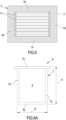
- figure 4 shows a nest comb box 2 having the lower passage aligned with the lower end of the comb frames 6.
- the box 2 according to figure 4 includes four flat lateral panels 3a, 3b, 3c, 3d delimiting a parallelepiped inner cavity, and opposite lateral panels are constantly parallel one to the other.
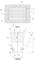
- Figure 7 shows a nest comb box 2 having (in a first cross-section view) a tapered inner configuration, particularly adapted to match (i.e. counter shaped to) the outer shape of the comb frames 6.
- the lateral wall 3 delimiting the inner cavity housing the brood chamber includes four lateral panels 3a, 3b, 3c, 3d delimiting a substantially parallelepiped inner cavity, in which two opposite lateral panels are parallel one another and the other two lateral panels have a thickness increasing on moving from an upper portion of the lateral wall 3 towards the lower portion of the lateral wall (3).
- the lateral wall 3 has no holes or cavities for putting into fluid communication the external environment with the inner cavity housing the brood chamber, e.g. neither an entrance for the bees, nor a vent is provided in the lateral wall 3. This is in order not to affect the proper thermal insulation of the hive.
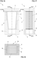
- the exclusive exception is the hive according to figure 16 , which is specifically designed for extremely warm condition were the external temperature is constantly higher than the requested brood chamber temperature (e.g. desert).
- two entrances are provided in the nest comb box 2, on opposite panels 3b, 3d to allow the bees and air to enter the hive.
- the two entrances define respective tortuous passages to properly direct air into the inner chamber and forcing a ventilation direction through the comb frames; e.g. an upper inlet on one side and a lower inlet at the other side as shown.
- the nest comb box 2 is configured to removably house a plurality of comb frames 6, in the form of polygonal structures, such as a square structure - fig.
- the comb frames 6 delimit and support the brood comb, which is the beeswax/plastic structure of cells where the queen bee lays eggs. It is the part of the beehive where a new brood is raised by the colony.
- the comb frame 6 is in one piece, i.e. the comb frames 6 are in the form of substantially flat bodies extending in a main plane.
- Each comb frame includes peripheral element or bars 7 delimiting an inner comb area 8 where a comb foundation sheet is placed.
- the semi-comb frames 6a, 6b may be fixedly joined together or not; however, a distance 'd' between the lower portion of the upper semi-comb frame 6a and the upper portion of the lower semi-comb frame 6b should be substantially zero.
- a comb frame is considered a single comb frame 6, even if made up of two one or more semi-comb frames, in case there is no gap between the bars, in particular no gap allowing the bees to pass there between.
- the inner comb area 8 has an overall one-side dimension of at least 12 dm 2 to provide sufficient space to the bee nest (correspondingly the overall inner comb area - two sides - of one single comb frame 6 should be at least 24 dm 2 ).
- each comb frame 6 is comprised between 12 and 50 dm 2 , preferentially between 15 and 28 dm 2 , in particular the overall one side dimension of the relevant solutions is about 20 dm 2 .
- a plurality of comb frames 6 are housed in parallel in the nest comb box 2 so that the overall dimension of the inner comb area 8 sum of all the comb frames 6 is higher than 100 dm 2 . This is considered a minimum dimension to generate a growing new bee colony.
- a more relevant range for the overall dimension of the inner comb area 8 of all the comb frames 6 is comprised between 150 and 350 dm 2 ; in particular the overall dimension of the inner comb area 8 of all the comb frames 6 having the best performances is comprised between 200 and 300 dm 2 .
- the comb frames 2 are housed into the nest comb box 2 parallel one with the other, having respective inner comb areas 8 facing one another. Referring to the enclosed figures, each comb frame 6 includes four bars 7 (e.g.
- the comb frame may include only three bars, the upper bar 7a and the two lateral bars 7c, 7d. In this latter configuration no lower bar 7b is used. In the following description four bars are referred to, however it is intended that the same comb frame configurations are equally included with no lower bar 7b (i.e. the lateral bars 7c, 7d are free at their respective lower portions.
- Each comb frame 6 is generally (even if not necessarily) removably housed into the nest comb box 2.
- the upper and the lower bars 7a, 7b may be substantially parallel to each other as shown in all embodiments.
- the comb frame 6 is normally symmetric with respect to a vertical axis V.
- the comb frame 6 is squared, having the four delimiting bars 7a-7d all having substantially the same extension (base B has a length equivalent to the height H).
- the upper bar 7a may have emerging sides to be received and housed in corresponding seats of the nest comb box lateral wall so that each comb frame 6 may be (removably) supported and correctly/precisely positioned in the inner housing.
- ⁇ ⁇ ); this is only exemplificative and simpler to manufacture.
- the angle ⁇ and/or ⁇ is included in a range between 1° and 15°; a good option is an angle of about 8°.
- the use of trapezoidal comb frames 6 allows to further increase the invention advantages because the frame barycenter is moved upward to warmer nest regions, increasing the fraction of the brood surface resident in highest brood temperature range.
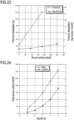
- fig. 4A shows the brood temperature versus the brood surface in a rational hive according to the embodiment of figure 4 (rectangular frame).
- the major part of the brood is set into the maximal brood acceptable range ( figure 4A ); the use of the trapezoidal optimized frame allows to set the major part of the brood surface into the maximal temperature range, ( figure 7A ) also for large brood deposition areas (300 dm 2 ). Comparison between the resultant surface/temperature ( figures 1B , 4A and 7A ) synthetizes the effect of the hive over the brood incubation temperature. Moving back to trapezoidal comb frames 6, the middle height (H/2) divides the frame into two regions, namely an upper area 8a and a lower area 8b of different surface. The ratio between the upper surface (with respect to the middle frame height) and the lower surface can be calculated and optimized.
- the ratio may be seen as an indication of the advantage obtained to enhance the brood surface temperature with respect to a rectangular frame.
- a ratio between the upper area 8a and the lower area 8b of the inner comb area 8 should be at least 1,05 and optionally at least 1,12 or greater.
- the comb frames 2 are housed into the nest comb box 2 parallel one with the other and having the respective inner comb areas 8 facing one another.
- the comb frames 2 lay vertically when in use in side by side relationship (see figure 2 , for example).
- a distance between a middle vertical plane of one comb frame 6 and a middle vertical plane of an adjacent comb frame 6 is substantially constant and included between 28 and 35 mm.
- a distance between a middle vertical plane of one comb frame and the lateral wall 3 of the nest comb box is substantially constant, too and included between 18 and 24 mm to allow the bees to build the cells on the frame side and then to pass in the remaining space. Also a distance between a lateral bar 7c; 7d of the bars 7 of each of the comb frames 6 and a lateral panel 3a; 3b; 3c; 3d of the box 2 should be substantially constant and included between 8 and 12 mm.
- the top cover 4 may have an overall thickness of at least 10 mm, in particular of at least 20 mm and more in particular of at least 40 mm to provide proper thermal insulation.
- the top cover 4 is box shaped to include a closed air chamber 15 confined between top and bottom panels 4a, 4b and lateral wall panels 4c.
- the top cover 4 of figure 11 may be used in anyone of the other disclosed embodiments.
- Figures 1 and 13 show a hive including at least one honey super 9 placed in correspondence of the upper passage of the nest comb box 2.
- a honey super consists of a box 10 in which e.g.
- cold brood leads to a degenerative process producing weaker generations of bees.
- the invention allows the colony to manage the brood temperature and rise the new generation at the highest brood temperature range, resulting in better biological bee synthesis.
- the described critical hive configuration allows optimal temperature control by the bees themselves. The effects are:
- honey bees always perform active temperature control, but uniquely into the optimized hive the colony is induced to perform an optimal temperature control.
- An optimal temperature control means that the bees can continuously (in time-seasons) set the temperature within a nest distribution (volume, gradient) not possible to be observed in standard hives. Because of the relation bee quality-temperature and because of other new phenomenon (e.g. the process to raise a new queen by the colony), the colony status follows divergent trajectories once reared in standard or optimized hive. In a short observation time (month/seasons), the colony develops faster with large population and lower honey consumption.
- the configuration limit corresponding to the hive dissipation parameter of about 0.006 [W/(dm 2 °C)] allows experimentally to observe the merging of the positive effects into a certain (more limited) range of the colonies (e.g. test data in Europe, 20% of the tested strains).
- the measures will be performed in a controlled ambient having the following conditions:
- Figures 29, 30 and 31 clearly identify the first sensor placement.
- a second sensor S 2 is positioned in the lower part of the tested rational hive structure between one lateral last foil 108 and the lateral penultimate foil 107 in a front position at a side opposite to the side where the first sensor S 1 is placed.
- Figures 29, 30 and 31 clearly identify the second sensor placement.
- a third sensor S 3 is positioned in the lower part of the tested rational hive structure between two central foils 103-104 in a front position at a side opposite to the front support foil 110 and not on the same side of the heater.
- Figures 29, 30 and 31 clearly identify the third sensor placement. Note that each sensor is exactly spaced 20 mm in vertical and horizontal direction towards the inside of the radiator as specifically indicated in the drawings.
- the described hive structures positively affect the colony population dynamics (unlikely to occur with standard hives).
- the positive influences are substantially obtained in any climatic region.
- the colony overall population may increase with respect to the standard hive up to three times. Moreover, increase of the overall population is seen in all seasons, as well as increase of foragers bee population. Increase of the brood surface in respect to standard colonies with identical population was observed. Increase of the maximal season brood surface and increase of the brood surface was achieved in any time during the season.
- the optimized hive provided increased robustness of the brood to suddenly temperature drops. Novelty in literature, brood surfaces in hives according to the invention were experimentally measured up to 300 dm 2 .
- the optimized hive provided increased possibility to produce artificial swarms and extension of the replication period. Indeed, a larger colony population, a reduced mortality and infestation, with faster build up, and a less overall work for the colony the invention allow to reproduce artificial swarms at a highest ratio 8:1.
- the optimized hive provided modification of the ratio between bees into the nest and flying bees in favor of the flying bees and a natural modification of the ratio between drones and workers at favor of workers. Presence of drones into the colony also in winter could be observed, (overwintering drones in cold climates - no brood).
- the bee population increases the surplus and pollination capability and the fly activity by extension of the daily flight hours, increase of the flight intensity, increase of the flight speed.
Landscapes
- Life Sciences & Earth Sciences (AREA)
- Environmental Sciences (AREA)
- Animal Husbandry (AREA)
- Biodiversity & Conservation Biology (AREA)
- Catching Or Destruction (AREA)
- Buildings Adapted To Withstand Abnormal External Influences (AREA)
Claims (15)
- Rationale Bienenstockstruktur (1), umfassend:- einen Nestwabenkasten (2), welcher eine Brutkammer für Bienen begrenzt, wobei der Nestwabenkasten eine laterale Wand (3) umfasst, welche einen inneren Hohlraum begrenzt, welcher die Brutkammer unterbringt;- eine obere Abdeckung (4), welche in einem oberen Abschnitt der Bienenstockstruktur angeordnet ist, um einen oberen Zugang zu der Bienenstockstruktur zu schließen;- ein unteres Schließelement (5), welches in einem unteren Abschnitt der Bienenstockstruktur angeordnet ist, um einen unteren Zugang zu der Bienenstockstruktur zu schließen;- eine Mehrzahl von Wabenrahmen (6) in der Form von im Wesentlichen flachen Körpern, welche sich in einer Hauptebene erstrecken, wobei jeder Wabenrahmen periphere Elemente oder Stäbe (7) umfasst, welche wenigstens einen Teil eines inneren Wabenbereichs (8) begrenzen,dadurch gekennzeichnet, dass der innere Wabenbereich (8) eine Gesamtabmessung einer Seite von wenigstens 15 dm2 aufweist;und dass die rationale Bienenstockstruktur einen bei 26 °C einer auferlegten Temperaturdifferenz gemessenen Bienenstock-Wärmeableitungsparameter zeigt, welcher niedriger als 0,00600 [W/(dm2·°C)] ist,und dass die laterale Wand (3) eine Wärmeleitfähigkeit aufweist, welche niedriger als 0,5 W/(m·K) ist.
- Rationale Bienenstockstruktur nach Anspruch 1, wobei der Wabenrahmen (6) eine polygonale Struktur, insbesondere eine rechteckige Struktur oder eine trapezförmige Struktur, aufweist, wobei der Wabenrahmen (6) in Bezug auf eine vertikale Achse symmetrisch ist und vier Stäbe (7) umfasst, welche miteinander verbunden sind, um den Wabenrahmen zu definieren, wobei ein oberer Stab (7a) mit der Einfügung zweier jeweiliger lateraler Stäbe (7c, 7d) mit einem unteren Stab (7b) verbunden ist, wobei der Wabenrahmen (6) innerhalb der Stäbe (7) eine Wabenfundamentlage umfasst und herausnehmbar in dem Nestwabenkasten (2) untergebracht ist, wobei der obere und der untere Stab (7a, 7b) im Wesentlichen parallel zueinander sind und ein oberer Stab (7a) des Wabenrahmens dazu eingerichtet ist, durch eine obere Seite der lateralen Wand (3) des Wabenrahmens aufgenommen und gehaltert zu sein.
- Rationale Bienenstockstruktur nach Anspruch 2, wobei der obere Stab (7a) länger ist als ein unterer Stab (7b) und laterale Stäbe (7c, 7d) eine im Wesentlichen äquivalente Länge aufweisen, wobei wenigstens einer der lateralen Stäbe (7c, 7d) in Bezug auf den oberen und den unteren Stab (7a, 7b) geneigt ist, um einen spitzen Winkel in Bezug auf den unteren Stab (7b) zu definieren, optional wobei beide lateralen Stäbe (7c, 7d) geneigt sind, um jeweilige spitze untere Winkel zu definieren.
- Rationale Bienenstockstruktur nach einem der vorherigen Ansprüche, wobei in einem Verwendungszustand die Mehrzahl von Wabenrahmen (6) vertikal in einer Seite-an-Seite-Beziehung liegt, wobei ein Abstand zwischen einer mittleren vertikalen Ebene eines Wabenrahmens und einer mittleren vertikalen Ebene eines benachbarten Wabenrahmens (6) im Wesentlichen konstant ist und zwischen 28 und 35 mm umfasst ist, wobei ein Abstand zwischen einer mittleren vertikalen Ebene eines Wabenrahmens und der lateralen Wand (3) des Nestwabenkastens im Wesentlichen konstant ist und zwischen 14 und 18 mm umfasst ist.
- Rationale Bienenstockstruktur nach einem der vorherigen Ansprüche, wobei in einem Verwendungszustand der Wabenrahmen (6) einen geometrischen Massenmittelpunkt aufweist, welcher in einer oberen Position in Bezug auf die Hälfte der Wabenrahmenhöhe platziert ist, wobei eine Linie entlang der mittleren Höhe den inneren Wabenbereich (8) in einen oberen Bereich (8a) und einen unteren Bereich (8b) teilt, wobei ein Verhältnis zwischen dem oberen Bereich (8a) und dem unteren Bereich (8b) des inneren Wabenbereichs (8) wenigstens 1,05 und optional wenigstens 1,12 oder größer ist, wobei in einem Verwendungszustand der Wabenrahmen (6) eine horizontale Gesamtabmessung aufweist, welche kleiner ist als eine vertikale Gesamtabmessung.
- Rationale Bienenstockstruktur nach einem der vorherigen Ansprüche, wobei der Wabenrahmen (6) trapezförmig ist, mit einer oberen Basis länger als einer unteren Basis und einem Rahmenwinkel von wenigstens 1° und optional von wenigstens 3° oder größer.
- Rationale Bienenstockstruktur nach einem der vorherigen Ansprüche, wobei in einem Verwendungszustand der Wabenrahmen (6) eine Höhe aufweist, welche länger als eine Basis ist, insbesondere wobei die Höhe des Wabenrahmens wenigstens 1,5-mal die Basis ist und im Detail zweimal die Basis ist.
- Rationale Bienenstockstruktur nach einem der vorherigen Ansprüche, wobei die Gesamtabmessung des inneren Wabenbereichs (8) jedes Wabenrahmens (6) zwischen 12 und 50 dm2 umfasst ist, insbesondere wobei die Gesamtabmessung zwischen 15 und 28 dm2 liegt, insbesondere etwa 20 dm2 beträgt, wobei die Gesamtabmessung des inneren Wabenbereichs (8) all der Wabenrahmen (6) zwischen 150 und 350 dm2 umfasst ist, insbesondere wobei die Gesamtabmessung des inneren Wabenbereichs (8) all der Wabenrahmen (6) zwischen 200 und 300 dm2 umfasst ist.
- Rationale Bienenstockstruktur nach einem der vorherigen Ansprüche, wobei die laterale Wand (3), welche den inneren Hohlraum begrenzt, welcher die Brutkammer unterbringt, vier laterale Paneele (3a, 3b, 3c, 3d) umfasst, welche einen im Wesentlichen parallelepipedförmigen inneren Hohlraum begrenzen, und optional wobei die laterale Wand (3) einen Wärmeübertragungskoeffizienten aufweist, welcher niedriger als 5 W/(m2·K), insbesondere niedriger als 3 W/(m2·K), ist,wobei die laterale Wand (3) eine minimale Dicke von etwa 20 mm, insbesondere größer als 30 mm, aufweist, insbesondere wobei die laterale Wand (3) aus Holz und/oder Polyurethan oder geschäumten Polymeren hergestellt ist, undwobei ein Abstand zwischen einem lateralen Stab (7c; 7d) der Stäbe (7) des Wabenrahmens (6) und einem lateralen Paneel (3a; 3b; 3c; 3d) im Wesentlichen konstant ist und zwischen 8 und 12 mm umfasst ist.
- Rationale Bienenstockstruktur nach einem der vorherigen Ansprüche, wobei die laterale Wand (3), welche den inneren Hohlraum begrenzt, welcher die Brutkammer unterbringt, vier laterale Paneele (3a, 3b, 3c, 3d) umfasst, welche einen im Wesentlichen parallelepipedförmigen inneren Hohlraum begrenzen, wobei zwei gegenüberliegende laterale Paneele parallel zueinander sind, wobei die anderen beiden lateralen Paneele eine Dicke aufweisen, welche sich von einem oberen Abschnitt der lateralen Wand (3) in Richtung des unteren Abschnitts der lateralen Wand (3) bewegend zunimmt.
- Rationale Bienenstockstruktur nach einem der vorherigen Ansprüche, wobei die laterale Wand (3) keine Löcher oder Hohlräume aufweist, um die äußere Umgebung mit dem inneren Hohlraum, welcher die Brutkammer unterbringt, in Fluidkommunikation zu versetzen, z. B. wobei weder ein Eingang für die Bienen noch eine Belüftung in der lateralen Wand (3) bereitgestellt ist, und
wobei die laterale Wand (3) von einer röhrenförmigen Konfiguration ist, welche einen oberen Durchgang und einen unteren Durchgang aufweist, wobei die obere Abdeckung (4) direkt den oberen Durchgang schließt, insbesondere wobei keine Löcher oder Hohlräume, um die äußere Umgebung mit dem inneren Hohlraum, welcher die Brutkammer unterbringt, in Fluidkommunikation zu versetzen, in der oberen Abdeckung (4) und/oder zwischen der oberen Abdeckung und der lateralen Wand (3) vorhanden sind. - Rationale Bienenstockstruktur nach Anspruch 11, ferner umfassend wenigstens einen Honigraum (9), welcher in Übereinstimmung mit dem oberen Durchgang des Nestwabenkastens (2) platziert ist, wobei der Honigraum (9) einen Kasten (10) und eine Mehrzahl von Rahmen für Honig (11) umfasst, wobei die Rahmen für Honig in dem Kasten aufgehängt sind, wobei der Kasten (10) keine Löcher oder Hohlräume aufweist, um die äußere Umgebung mit einem inneren Hohlraum des Kastens in Fluidkommunikation zu versetzen, wobei die obere Abdeckung (4) einen oberen Teil des Kastens (10) direkt schließt, insbesondere wobei keine Löcher oder Hohlräume, um die äußere Umgebung mit einem inneren Hohlraum, welcher die Brutkammer unterbringt, in Fluidkommunikation zu versetzen, zwischen der oberen Abdeckung und dem Kasten (10) vorhanden sind.
- Rationale Bienenstockstruktur nach einem der vorherigen Ansprüche, wobei die obere Abdeckung (4) eine Gesamtdicke von wenigstens 10 mm, insbesondere von wenigstens 20 mm und noch bevorzugter von wenigstens 40 mm, aufweist und kastenförmig ist, umfassend eine geschlossene Luftkammer (15), welche zwischen einem oberen und einem unteren Paneel (4a, 4b) und lateralen Wandpaneelen (4c) eingeschlossen ist.
- Rationale Bienenstockstruktur nach einem der vorherigen Ansprüche, ferner umfassend ein unteres Gehäuse (12), welches unterhalb des Nestwabenkastens (2) platziert ist, insbesondere wobei der Nestwabenkasten und das untere Gehäuse separate und verschiedene Elemente sind, wobei das untere Gehäuse (12) eine laterale Hilfswand (13) umfasst, welche einen unteren Hohlraum begrenzt, wobei in einem Verwendungszustand die Wabenrahmen (6) vorzugsweise nicht in dem unteren Hohlraum untergebracht sind,
wobei das untere Gehäuse (12) einen Bieneneingang (14) umfasst, wobei der Bieneneingang (14) in einem Abstand (D), insbesondere einem vertikalen Abstand zwischen dem Eingang (14) und einem unteren Stab (7d) der Wabenrahmen (6), von den Wabenrahmen (6) von wenigstens 15 mm liegt, wobei der Abstand (D) kleiner ist als 200 mm und insbesondere wobei der Abstand wenigstens zwischen 100 und 120 mm beträgt. - Rationale Bienenstockstruktur nach Anspruch 14, wobei der Bieneneingang (14) in der Form eines länglichen horizontalen Schlitzes vorliegt, insbesondere wobei eine Höhe des Schlitzes zwischen 8 und 16 mm liegt und insbesondere etwa 12 mm beträgt, wobei sich die Wabenrahmen weg von dem Bieneneingang erstrecken, und
wobei die laterale Hilfswand (3) von einer röhrenförmigen Konfiguration ist, welche einen oberen Durchgang und einen unteren Durchgang aufweist, wobei der obere Durchgang das untere Gehäuse (12) mit dem Nestwabenkasten (2) in Fluidkommunikation versetzt, wobei das untere Schließelement (5) den unteren Durchgang der lateralen Hilfswand (3) schließt.
Applications Claiming Priority (2)
| Application Number | Priority Date | Filing Date | Title |
|---|---|---|---|
| EP17166379 | 2017-04-12 | ||
| PCT/EP2018/059405 WO2018189302A1 (en) | 2017-04-12 | 2018-04-12 | Rational hive structure |
Publications (3)
| Publication Number | Publication Date |
|---|---|
| EP3609317A1 EP3609317A1 (de) | 2020-02-19 |
| EP3609317C0 EP3609317C0 (de) | 2024-07-10 |
| EP3609317B1 true EP3609317B1 (de) | 2024-07-10 |
Family
ID=58547382
Family Applications (1)
| Application Number | Title | Priority Date | Filing Date |
|---|---|---|---|
| EP18717363.8A Active EP3609317B1 (de) | 2017-04-12 | 2018-04-12 | Rationale bienenstockstruktur |
Country Status (5)
| Country | Link |
|---|---|
| US (1) | US11375697B2 (de) |
| EP (1) | EP3609317B1 (de) |
| AU (1) | AU2018252144B2 (de) |
| CA (1) | CA3059654A1 (de) |
| WO (1) | WO2018189302A1 (de) |
Families Citing this family (6)
| Publication number | Priority date | Publication date | Assignee | Title |
|---|---|---|---|---|
| US11957113B2 (en) | 2017-11-13 | 2024-04-16 | Beewise Technologies Ltd | Automatic beehives |
| MX2022003573A (es) | 2019-09-24 | 2022-06-14 | Beewise Tech Ltd | Estructuras y metodos para remocion de bastidores de colmenas y puerta para abejas. |
| FR3103670B1 (fr) * | 2019-11-27 | 2021-10-15 | Valeo Systemes Thermiques | Radiateur électrique avec dispositif de mesure de température |
| FR3119080B1 (fr) * | 2021-01-28 | 2023-01-20 | Surface Composee Production Et Assemblage | Partition rayonnante pour ruche |
| US11895989B2 (en) | 2022-07-04 | 2024-02-13 | Beewise Technologies Ltd | Automated beehive control and management |
| US12324421B2 (en) | 2022-07-04 | 2025-06-10 | Beewise Technologies Ltd | Array of gates in automated bee habitat |
Family Cites Families (30)
| Publication number | Priority date | Publication date | Assignee | Title |
|---|---|---|---|---|
| US221284A (en) * | 1879-11-04 | Improvement in honey-boxes for bee-hives | ||
| US22059A (en) * | 1858-11-16 | Beehive | ||
| US110517A (en) * | 1870-12-27 | Edward walker | ||
| US212047A (en) * | 1879-02-04 | Improvement in honey-boxes for bee-hives | ||
| US129464A (en) * | 1872-07-16 | 1872-07-16 | Improvement in bee-hives | |
| US2300772A (en) * | 1941-04-17 | 1942-11-03 | Robert E Borland | Beehive |
| CH257646A (de) | 1945-11-02 | 1948-10-31 | Thuer Johann | Beutekasten mit Rahmenblock. |
| DE2539494A1 (de) | 1975-09-05 | 1977-03-10 | Matthias Schmidt | Kunststoffbienenwabenanordnung |
| DE8026761U1 (de) | 1980-10-07 | 1981-03-19 | Kemner, Fritz, 2800 Bremen | Bienenbeute |
| US4349927A (en) * | 1981-02-19 | 1982-09-21 | Adams Iv John Q | Beehive improvements |
| US4402099A (en) | 1981-05-04 | 1983-09-06 | Chevron Research | Beehive for improved beekeeping in tropical countries |
| US4546509A (en) * | 1984-01-23 | 1985-10-15 | Peter Huetter | Multiple queen beehive |
| US4639962A (en) | 1984-02-21 | 1987-02-03 | Hogg John A | Apparatus for comb honey |
| US5162014A (en) | 1991-05-03 | 1992-11-10 | Moore Lawrence W | Magnetic treating of honeybees infested with mites or other parasites |
| US6475061B1 (en) | 2000-11-01 | 2002-11-05 | Board Of Trustees Of Michigan State University | Method and apparatus for control of mites in a beehive |
| LV13344B (en) | 2005-03-31 | 2005-10-20 | Zarinka Janis Jekabpils Piena | Bee-hive and its arrangement in the container |
| NL1033172C2 (nl) | 2007-01-05 | 2009-04-21 | Imkerij Mamamoer | Broedkamer voor Nederlandse Simplex-ramen. |
| US8814630B2 (en) | 2011-01-04 | 2014-08-26 | Carl T. Rittberger | PVC beehive |
| IN2014MN01444A (de) | 2011-12-21 | 2015-04-03 | Cedar Anderson | |
| RU2481769C1 (ru) | 2012-02-22 | 2013-05-20 | Владимир Николаевич Антоненко | Улей "жужу" |
| US20140127969A1 (en) * | 2012-11-07 | 2014-05-08 | Paul Mullins | Man-made beehive |
| HU230613B1 (hu) * | 2013-11-29 | 2017-04-28 | Béla DÖMÖCSÖK | Rácsgyűrűs fészekkeret hengerfészkes kaptárokhoz |
| US20160015007A1 (en) | 2014-07-17 | 2016-01-21 | George Sinanis | Method and Apparatus for Managing a Bee Hive |
| HU5127U (hu) | 2014-11-26 | 2020-03-30 | Fendrik Peter Dr | Állítható magasságú méhészeti keret |
| US9807985B2 (en) * | 2015-01-27 | 2017-11-07 | Igor Bulanyy | System for controlling climate and moisture in beehive |
| US20170055501A1 (en) * | 2015-06-11 | 2017-03-02 | Joseph D. Forte | Honey Frame Hanger |
| US20170208779A1 (en) * | 2016-01-25 | 2017-07-27 | Todd Rubright | Beehive Assembly |
| CN205455340U (zh) | 2016-04-08 | 2016-08-17 | 浙江天依蜂蜂业有限公司 | 一种新型多功能蜂箱 |
| CN205865597U (zh) * | 2016-08-16 | 2017-01-11 | 阳光蜂慧(北京)蜜蜂医疗科学技术有限公司 | 一种自动调节散热养蜂箱 |
| US20180116182A1 (en) * | 2016-11-02 | 2018-05-03 | William Theodoro Frey | Beehive protection system (The Hive Jacket) |
-
2018
- 2018-04-04 US US16/604,731 patent/US11375697B2/en active Active
- 2018-04-12 WO PCT/EP2018/059405 patent/WO2018189302A1/en not_active Ceased
- 2018-04-12 AU AU2018252144A patent/AU2018252144B2/en active Active
- 2018-04-12 CA CA3059654A patent/CA3059654A1/en active Pending
- 2018-04-12 EP EP18717363.8A patent/EP3609317B1/de active Active
Also Published As
| Publication number | Publication date |
|---|---|
| AU2018252144B2 (en) | 2023-11-16 |
| EP3609317A1 (de) | 2020-02-19 |
| WO2018189302A1 (en) | 2018-10-18 |
| US11375697B2 (en) | 2022-07-05 |
| EP3609317C0 (de) | 2024-07-10 |
| AU2018252144A1 (en) | 2019-11-28 |
| US20210161107A1 (en) | 2021-06-03 |
| CA3059654A1 (en) | 2018-10-18 |
Similar Documents
| Publication | Publication Date | Title |
|---|---|---|
| AU2018252144B2 (en) | Rational hive structure | |
| Seeley et al. | Survival of honeybees in cold climates: the critical timing of colony growth and reproduction | |
| Abou-Shaara et al. | Honey bee colonies performance enhance by newly modified beehives | |
| Mitchell | Ratios of colony mass to thermal conductance of tree and man-made nest enclosures of Apis mellifera: implications for survival, clustering, humidity regulation and Varroa destructor | |
| CN106231895B (zh) | 无箱式蜂箱 | |
| CN103141410A (zh) | 内圆外方自动恒温中蜂蜂箱 | |
| CN114403053A (zh) | 一种中蜂高效繁育装置及繁育方法 | |
| CN104285905A (zh) | 一种蜜蜂的养殖方法 | |
| EA029128B1 (ru) | Сетчатая кольцевая рамка для сотов с расплодом для ульев с цилиндрическими гнездовыми корпусами | |
| CN112021263B (zh) | 一种运用循环组合巢框蜂箱的养蜂方法 | |
| CN107912330A (zh) | 田字形蜜蜂蜂箱的使用方法 | |
| Hauser et al. | The effect of the age of the honey bee (Apis mellifera L) queen on worker population, swarming and honey yields in a subtropical climate | |
| Chinh et al. | Production of reproductives in the honey bee species Apis cerana in northern Vietnam | |
| RU159830U1 (ru) | Улей-универсал | |
| Schafaschek et al. | Performance of Africanized honeybee colonies settled by queens selected for different traits | |
| CN110810341A (zh) | 一种适合于成熟蜜生产的蜜蜂蜂群越冬养殖方法 | |
| WO2015186977A1 (ko) | 양봉용 소초 | |
| CN212232674U (zh) | 一种蜜蜂养殖用循环组合式巢框及蜂箱 | |
| Saini et al. | Apis mellifera colony productivity and growth influenced by initial frame strength: Farmer’s perspective | |
| Taylor Jr et al. | Swarm boxes and Africanized honeybees: Some preliminary observations | |
| Olszewski et al. | Drone and Worker Brood Was Unexpectedly Well Heated Both in Standard-Cell and Small-Cell Comb Colonies | |
| Fursov et al. | POSITIVE EFFECT OF INNOVATIVE CONSTRUCTION OF THREE-STOREY VASYL PRIYATELENKO’S BEEHIVE ON DEVELOPMENT, HEALTH AND PRODUCTIVITY OF HONEYBEE COLONIES | |
| Iqbal et al. | Comparative analysis of colony growth in honeybees (Apis mellifera) in wooden and insulated Langstroth hives under varied environmental conditions | |
| CN211832395U (zh) | 一种用于规模化养殖的一体式蜂箱 | |
| Heaf | Sustainable bee-friendly beekeeping with the Warré hive |
Legal Events
| Date | Code | Title | Description |
|---|---|---|---|
| STAA | Information on the status of an ep patent application or granted ep patent |
Free format text: STATUS: UNKNOWN |
|
| STAA | Information on the status of an ep patent application or granted ep patent |
Free format text: STATUS: THE INTERNATIONAL PUBLICATION HAS BEEN MADE |
|
| PUAI | Public reference made under article 153(3) epc to a published international application that has entered the european phase |
Free format text: ORIGINAL CODE: 0009012 |
|
| STAA | Information on the status of an ep patent application or granted ep patent |
Free format text: STATUS: REQUEST FOR EXAMINATION WAS MADE |
|
| 17P | Request for examination filed |
Effective date: 20191107 |
|
| AK | Designated contracting states |
Kind code of ref document: A1 Designated state(s): AL AT BE BG CH CY CZ DE DK EE ES FI FR GB GR HR HU IE IS IT LI LT LU LV MC MK MT NL NO PL PT RO RS SE SI SK SM TR |
|
| AX | Request for extension of the european patent |
Extension state: BA ME |
|
| DAV | Request for validation of the european patent (deleted) | ||
| DAX | Request for extension of the european patent (deleted) | ||
| STAA | Information on the status of an ep patent application or granted ep patent |
Free format text: STATUS: EXAMINATION IS IN PROGRESS |
|
| 17Q | First examination report despatched |
Effective date: 20230316 |
|
| GRAP | Despatch of communication of intention to grant a patent |
Free format text: ORIGINAL CODE: EPIDOSNIGR1 |
|
| STAA | Information on the status of an ep patent application or granted ep patent |
Free format text: STATUS: GRANT OF PATENT IS INTENDED |
|
| INTG | Intention to grant announced |
Effective date: 20240202 |
|
| GRAS | Grant fee paid |
Free format text: ORIGINAL CODE: EPIDOSNIGR3 |
|
| GRAA | (expected) grant |
Free format text: ORIGINAL CODE: 0009210 |
|
| STAA | Information on the status of an ep patent application or granted ep patent |
Free format text: STATUS: THE PATENT HAS BEEN GRANTED |
|
| AK | Designated contracting states |
Kind code of ref document: B1 Designated state(s): AL AT BE BG CH CY CZ DE DK EE ES FI FR GB GR HR HU IE IS IT LI LT LU LV MC MK MT NL NO PL PT RO RS SE SI SK SM TR |
|
| REG | Reference to a national code |
Ref country code: CH Ref legal event code: EP |
|
| REG | Reference to a national code |
Ref country code: DE Ref legal event code: R096 Ref document number: 602018071536 Country of ref document: DE |
|
| U01 | Request for unitary effect filed |
Effective date: 20240723 |
|
| U07 | Unitary effect registered |
Designated state(s): AT BE BG DE DK EE FI FR IT LT LU LV MT NL PT RO SE SI Effective date: 20240902 |
|
| PG25 | Lapsed in a contracting state [announced via postgrant information from national office to epo] |
Ref country code: NO Free format text: LAPSE BECAUSE OF FAILURE TO SUBMIT A TRANSLATION OF THE DESCRIPTION OR TO PAY THE FEE WITHIN THE PRESCRIBED TIME-LIMIT Effective date: 20241010 |
|
| PG25 | Lapsed in a contracting state [announced via postgrant information from national office to epo] |
Ref country code: GR Free format text: LAPSE BECAUSE OF FAILURE TO SUBMIT A TRANSLATION OF THE DESCRIPTION OR TO PAY THE FEE WITHIN THE PRESCRIBED TIME-LIMIT Effective date: 20241011 Ref country code: PL Free format text: LAPSE BECAUSE OF FAILURE TO SUBMIT A TRANSLATION OF THE DESCRIPTION OR TO PAY THE FEE WITHIN THE PRESCRIBED TIME-LIMIT Effective date: 20240710 |
|
| PG25 | Lapsed in a contracting state [announced via postgrant information from national office to epo] |
Ref country code: IS Free format text: LAPSE BECAUSE OF FAILURE TO SUBMIT A TRANSLATION OF THE DESCRIPTION OR TO PAY THE FEE WITHIN THE PRESCRIBED TIME-LIMIT Effective date: 20241110 |
|
| PG25 | Lapsed in a contracting state [announced via postgrant information from national office to epo] |
Ref country code: HR Free format text: LAPSE BECAUSE OF FAILURE TO SUBMIT A TRANSLATION OF THE DESCRIPTION OR TO PAY THE FEE WITHIN THE PRESCRIBED TIME-LIMIT Effective date: 20240710 |
|
| PG25 | Lapsed in a contracting state [announced via postgrant information from national office to epo] |
Ref country code: ES Free format text: LAPSE BECAUSE OF FAILURE TO SUBMIT A TRANSLATION OF THE DESCRIPTION OR TO PAY THE FEE WITHIN THE PRESCRIBED TIME-LIMIT Effective date: 20240710 Ref country code: RS Free format text: LAPSE BECAUSE OF FAILURE TO SUBMIT A TRANSLATION OF THE DESCRIPTION OR TO PAY THE FEE WITHIN THE PRESCRIBED TIME-LIMIT Effective date: 20241010 |
|
| PG25 | Lapsed in a contracting state [announced via postgrant information from national office to epo] |
Ref country code: RS Free format text: LAPSE BECAUSE OF FAILURE TO SUBMIT A TRANSLATION OF THE DESCRIPTION OR TO PAY THE FEE WITHIN THE PRESCRIBED TIME-LIMIT Effective date: 20241010 Ref country code: PL Free format text: LAPSE BECAUSE OF FAILURE TO SUBMIT A TRANSLATION OF THE DESCRIPTION OR TO PAY THE FEE WITHIN THE PRESCRIBED TIME-LIMIT Effective date: 20240710 Ref country code: NO Free format text: LAPSE BECAUSE OF FAILURE TO SUBMIT A TRANSLATION OF THE DESCRIPTION OR TO PAY THE FEE WITHIN THE PRESCRIBED TIME-LIMIT Effective date: 20241010 Ref country code: IS Free format text: LAPSE BECAUSE OF FAILURE TO SUBMIT A TRANSLATION OF THE DESCRIPTION OR TO PAY THE FEE WITHIN THE PRESCRIBED TIME-LIMIT Effective date: 20241110 Ref country code: HR Free format text: LAPSE BECAUSE OF FAILURE TO SUBMIT A TRANSLATION OF THE DESCRIPTION OR TO PAY THE FEE WITHIN THE PRESCRIBED TIME-LIMIT Effective date: 20240710 Ref country code: GR Free format text: LAPSE BECAUSE OF FAILURE TO SUBMIT A TRANSLATION OF THE DESCRIPTION OR TO PAY THE FEE WITHIN THE PRESCRIBED TIME-LIMIT Effective date: 20241011 Ref country code: ES Free format text: LAPSE BECAUSE OF FAILURE TO SUBMIT A TRANSLATION OF THE DESCRIPTION OR TO PAY THE FEE WITHIN THE PRESCRIBED TIME-LIMIT Effective date: 20240710 |
|
| PG25 | Lapsed in a contracting state [announced via postgrant information from national office to epo] |
Ref country code: SM Free format text: LAPSE BECAUSE OF FAILURE TO SUBMIT A TRANSLATION OF THE DESCRIPTION OR TO PAY THE FEE WITHIN THE PRESCRIBED TIME-LIMIT Effective date: 20240710 |
|
| PG25 | Lapsed in a contracting state [announced via postgrant information from national office to epo] |
Ref country code: CZ Free format text: LAPSE BECAUSE OF FAILURE TO SUBMIT A TRANSLATION OF THE DESCRIPTION OR TO PAY THE FEE WITHIN THE PRESCRIBED TIME-LIMIT Effective date: 20240710 |
|
| PG25 | Lapsed in a contracting state [announced via postgrant information from national office to epo] |
Ref country code: SK Free format text: LAPSE BECAUSE OF FAILURE TO SUBMIT A TRANSLATION OF THE DESCRIPTION OR TO PAY THE FEE WITHIN THE PRESCRIBED TIME-LIMIT Effective date: 20240710 |
|
| PLBE | No opposition filed within time limit |
Free format text: ORIGINAL CODE: 0009261 |
|
| STAA | Information on the status of an ep patent application or granted ep patent |
Free format text: STATUS: NO OPPOSITION FILED WITHIN TIME LIMIT |
|
| U20 | Renewal fee for the european patent with unitary effect paid |
Year of fee payment: 8 Effective date: 20250424 |
|
| 26N | No opposition filed |
Effective date: 20250411 |
|
| REG | Reference to a national code |
Ref country code: CH Ref legal event code: H13 Free format text: ST27 STATUS EVENT CODE: U-0-0-H10-H13 (AS PROVIDED BY THE NATIONAL OFFICE) Effective date: 20251125 |
|
| PG25 | Lapsed in a contracting state [announced via postgrant information from national office to epo] |
Ref country code: MC Free format text: LAPSE BECAUSE OF FAILURE TO SUBMIT A TRANSLATION OF THE DESCRIPTION OR TO PAY THE FEE WITHIN THE PRESCRIBED TIME-LIMIT Effective date: 20240710 |
|
| GBPC | Gb: european patent ceased through non-payment of renewal fee |
Effective date: 20250412 |
|
| PG25 | Lapsed in a contracting state [announced via postgrant information from national office to epo] |
Ref country code: GB Free format text: LAPSE BECAUSE OF NON-PAYMENT OF DUE FEES Effective date: 20250412 |
|
| PG25 | Lapsed in a contracting state [announced via postgrant information from national office to epo] |
Ref country code: CH Free format text: LAPSE BECAUSE OF NON-PAYMENT OF DUE FEES Effective date: 20250430 |
|
| REG | Reference to a national code |
Ref country code: CH Ref legal event code: Y10 Free format text: ST27 STATUS EVENT CODE: U-0-0-Y10-Y00 (AS PROVIDED BY THE NATIONAL OFFICE) Effective date: 20260218 |
|
| RIN2 | Information on inventor provided after grant (corrected) |
Inventor name: GAMBERONI, ALESSANDRO Inventor name: RIGANTI, GIANMARIO |
|
| U1K | Transfer of rights of the unitary patent after the registration of the unitary effect |
Owner name: BEEHELPFUL SA; CH |
|
| PG25 | Lapsed in a contracting state [announced via postgrant information from national office to epo] |
Ref country code: IE Free format text: LAPSE BECAUSE OF NON-PAYMENT OF DUE FEES Effective date: 20250412 |
|
| PGFP | Annual fee paid to national office [announced via postgrant information from national office to epo] |
Ref country code: TR Payment date: 20260326 Year of fee payment: 9 |