EP3609141B1 - Ethernet-bonding-prozessor und entsprechender ethernet frame empfänger - Google Patents
Ethernet-bonding-prozessor und entsprechender ethernet frame empfänger Download PDFInfo
- Publication number
- EP3609141B1 EP3609141B1 EP18187834.9A EP18187834A EP3609141B1 EP 3609141 B1 EP3609141 B1 EP 3609141B1 EP 18187834 A EP18187834 A EP 18187834A EP 3609141 B1 EP3609141 B1 EP 3609141B1
- Authority
- EP
- European Patent Office
- Prior art keywords
- packets
- ethernet
- ethernet frames
- sequence
- sequence number
- Prior art date
- Legal status (The legal status is an assumption and is not a legal conclusion. Google has not performed a legal analysis and makes no representation as to the accuracy of the status listed.)
- Active
Links
Images


Classifications
-
- H—ELECTRICITY
- H04—ELECTRIC COMMUNICATION TECHNIQUE
- H04L—TRANSMISSION OF DIGITAL INFORMATION, e.g. TELEGRAPHIC COMMUNICATION
- H04L45/00—Routing or path finding of packets in data switching networks
- H04L45/24—Multipath
- H04L45/245—Link aggregation, e.g. trunking
-
- H—ELECTRICITY
- H04—ELECTRIC COMMUNICATION TECHNIQUE
- H04L—TRANSMISSION OF DIGITAL INFORMATION, e.g. TELEGRAPHIC COMMUNICATION
- H04L47/00—Traffic control in data switching networks
- H04L47/10—Flow control; Congestion control
- H04L47/34—Flow control; Congestion control ensuring sequence integrity, e.g. using sequence numbers
Definitions
- Various example embodiments relate to bonding of plural physical Ethernet interfaces into a single logical Ethernet interface. More particularly, embodiments of the invention relate to backwards compatible bonding of physical data interfaces that transfer Ethernet frames or packets, in a network where also non-bonded transmission takes place.
- the physical upper bound for the bit rate of an optical bit stream on a single optical wavelength channel across the Optical Distribution Network (abbreviated ODN) of a Passive Optical Network (abbreviated PON) lies at 25 Gigabit per second (abbreviated Gb/s).
- ODN Optical Distribution Network
- PON Passive Optical Network
- Gb/s 25 Gigabit per second
- a PON can carry multiple bit streams between the Optical Line Termination (abbreviated OLT) in the Central Office (abbreviated CO) and the Optical Network Unit (abbreviated ONU) in a cabinet or at the subscriber premises.
- OLT Optical Line Termination
- CO Central Office
- ONU Optical Network Unit
- a PON can carry an N-fold of the upper bound on the physical data rate of a single optical wavelength channel.
- N-fold data rate is not available on an individual OLT-ONU path, which at this time uses only a single wavelength.
- the capacity on such path remains limited to the upper bound on the physical data rate that can be carried by a single optical wavelength channel, which at present lies at about 25 Gigabit per second (abbreviated Gb/s).
- An atomic Ethernet frame data flow is a flow wherein the order of data frames (or data blocks in case a frame is fragmented) as transmitted by the sending service application must remain unaltered at the receiving service application. This order constraint does not apply to Ethernet frames or packets that are part of different atomic flows. Transmission of Ethernet frames or packets across an aggregate of multiple physical interfaces carrying Ethernet frames or packets, that are bonded into a single logical interface carrying Ethernet frames or packets, by means of an existing or new bonding paradigm, faces the problem of potentially different transmission latencies on each of the physical interfaces carrying Ethernet frames or packets, members of the aggregate logical interface carrying Ethernet frames or packets.
- Such differences in transmission latency can find their origin at different layers of the applied data transfer mechanism, like for instance the physical layer, the modulation rate, the scheduling phase, etc.
- These differences in latency between different physical interfaces carrying Ethernet frames or packets, that are bonded into a logical interface carrying Ethernet frames or packets with increased capacity may cause Ethernet frames or packets belonging to the same atomic Ethernet flow to be mis-ordered upon arrival when these data frames were transmitted in a distributed manner across the different member physical links carrying Ethernet frames or packets. Consequently, use of bonded physical media configurations requires technological measures to guarantee that the original Ethernet frame order is preserved at least within atomic data flows of Ethernet frames or packets.
- NEs Network Elements
- LAG Link Aggregation Group
- Ethernet Link Aggregation Group or LAG concept allows to combine multiple physical links carrying Ethernet frames or packets in a single logical link carrying Ethernet frames or packets between two network elements using Ethernet as data transport layer protocol. Without frame order preserving measures, mis-ordering of Ethernet frames or packets might occur on a LAG. Even at a same nominal rate, actual transmission speeds on the physical links can deviate up to approximately 100 ppm (parts per million). On top of that, consecutive Ethernet frames or packets vary considerably in size and thus in duration. This makes transmission of Ethernet frames or packets across multiple physical member links in a LAG susceptible to transmission latency variation, and hence to mis-ordering of Ethernet frames or packets arriving at different end-points.
- LAG specific interface logic avoids this from happening by ensuring that Ethernet frames or packets belonging to a same atomic Ethernet flow, i.e. a flow wherein mis-ordering of frames must be avoided, are confined to a same physical member link of the LAG at least during periods wherein the atomic Ethernet flow exhibits Ethernet frame arrival intervals that are smaller than the maximum potential transmission latency difference between the physical LAG members.
- This is realized by identifying Ethernet frames or packets of a same atomic Ethernet flow through recognizing frame header fields of which the content is specific and invariant for all frames of that same flow. These header fields are used as argument for a hashing function, the result of which indicates the physical member link of the LAG to be used for transmission of the respective Ethernet frame.
- the LAG paradigm makes four assumptions that are specific to the physical link data layer protocol.
- a first assumption the overall data traffic to be conveyed across a LAG aggregating multiple physical links does not consist of a single atomic Ethernet data flow, yet consists of plural atomic Ethernet flows. Only such a traffic profile allows to distribute at all the aggregate load of Ethernet frames or packets to be transported on the logical interface across the multiple physical links in the LAG according to their atomic Ethernet flow membership, while avoiding mis-ordering within a same atomic Ethernet flow.
- the data rate for each of these atomic Ethernet flows is two or more orders of magnitude smaller than the data rate on a physical member link of the LAG.
- the density of the result space of the applied hash function using the content of fields in the headers of transmitted Ethernet frames or packets that are specific and invariant within each atomic Ethernet flow, is more or less constant. Only a traffic profile with these properties allows to distribute the aggregate load of Ethernet frames or packets to be transported on the logical interface across the multiple physical links in the LAG, in a balanced manner with sufficient statistical probability across all member physical links of the LAG.
- the data rate on each of the member physical links of the LAG is about equal. The latter 3 assumptions are not fundamental requirements of the LAG concept, but they heavily determine the efficiency of the LAG and the risk of frame loss on individual physical member links, despite sufficient aggregate transmission capacity.
- any technological measures taken to preserve or restore the order of Ethernet frames or packets can be applied to all Ethernet frame traffic. Consequently, the frame order preserving or restoring techniques can be disruptive and specific for the bonding configuration and equipment.
- any technology deployed to ensure Ethernet frame order preservation at least within atomic Ethernet data flows must be backwards compatible with pre-bonding Ethernet frame formatting, at least to such level that legacy end-points that do not support bonding can properly parse Ethernet frames or packets with and without bonding supporting attributes, and discard the ones with bonding supporting attributes, as not intended for them.
- United States Patent US 9,699,102 B2 entitled “Very High Speed Cable Modem for Increasing Bandwidth”, describes a bonding processor (26 in FIG. 2 ) for bonding plural physical interfaces (27 in FIG. 2 ) carrying Ethernet packets that belong to a single Ethernet data flow ( FIG. 3 : A).
- the bonding technology is backwards compatible enabling non-bonded transmissions over the same physical interfaces (Col. 7, In. 63-65).
- a sequence number is inserted in Ethernet packets of a bonded data flow (Col. 3, In. 12-15) to enable resequencing at the receiver side, and the packets belonging to a bonded flow are distributed over the physical interfaces in line with a load balancing algorithm (Col. 3, In. 29-43).
- the load balancing may be achieved through a round robin mechanism or alternate scheduling algorithm.
- MAC Medium Access Control
- a bonding processor for backwards compatible bonding of plural physical interfaces carrying Ethernet frames or packets into a single logical interface carrying Ethernet frames or packets, allowing bonded transmission of a selected Ethernet data flow from a source network element to a destination network element in a network wherein said physical interfaces carrying Ethernet frames or packets are also used for non-bonded transmission, said bonding processor comprising:
- embodiments of the invention concern a dedicated bonding processor, typically located at the ingress of the MAC transmitter function and at the egress of the MAC receiver function.
- the bonding processor introduces a re-sequencing capability using sequence numbers that are inserted in the Ethernet frames or packets of Ethernet data flows that are transmitted over the bonding group.
- the re-sequencing capability based on sequence numbers avoids the need for tight coordination of data partitioning and data transmission using multiple physical media interfaces, for instance multiple optical wavelength channel MAC transmitters.
- the sequence numbers are added to the Ethernet frames or packets using a method that is backwards compatible with the IEEE 802.3 Ethernet specification to allow mixing sequence-numbered Ethernet frames or packets for bonded transmission with non-sequence-numbered Ethernet frames or packets for non-bonded transmissions to legacy endpoints over a single physical medium interface, like for instance a single optical wavelength channel.
- the bonding processor according to embodiments of the invention further introduces a load balancing function across member physical interfaces of a bonding group, the load balancing function considering also the length of each Ethernet frame in addition to its source and destination identifiers.
- the length of the payload section of Ethernet frames or packets can vary substantially, ranging for instance from 46 octets to 1500 octets, it is important that the size or length of individual Ethernet frames or packets is considered in the assignment of Ethernet frames or packets to member physical interfaces of a bonding group in order to achieve a balanced load across the member physical interfaces.
- the load distribution criterion obviously may consider additional parameters like for instance the relative data rate of the respective member physical interfaces.
- the bonding processor according to embodiments of the invention further also introduces synchronized timeslot reservation amongst bonded physical interfaces such that the Ethernet frames or packets to/from a bonded endpoint are transmitted with little or no time difference on concurrent, same data rate, bonded physical interfaces.
- the bonding processor avoids large propagation delay differences or scheduling skew between Ethernet frames or packets or frame fragments sent to a same bonding destination through adapted timeslot scheduling for member physical interfaces of a bonding group. This allows to keep the amount of re-sequencing buffering required at the receiver side of a bonding group to restore the order of Ethernet frames or packets in an Ethernet flow within limits.
- the means for inserting a sequence number comprise:
- embodiments of the invention rely on a specific sequence number field that is inserted in each Ethernet frame of one or more transmitted flows of Ethernet frames or packets.
- the sequence number field is inserted at the Ethernet protocol layer in a manner that is backwards compatible with the existing standard specifications for this layer.
- the sequence number field has the form of a 2-octet long field compatible with the existing Ethernet packet header format by insertion after the 2-octet Ethertype / Length field that ends a traditional Ethernet frame header.
- the 2-octet sequence number field is dedicated to contain a sequence number representative for the order of the Ethernet frame in the atomic Ethernet data flow where it forms part of.
- a bonding processor in the destination receiver is configured to assume the presence of this 2-octet field depending on the MAC destination address and interpret this 2-octet field correctly for re-sequencing
- the means for inserting a sequence number comprise:
- embodiments of the invention rely on a specific sequence number field that is inserted in each Ethernet frame of one or more transmitted flows of Ethernet frames or packets.
- the sequence number field is inserted at the Ethernet protocol layer in a manner that is backwards compatible with the existing standard specifications for this layer.
- the sequence number field has the form of a 4-octet long field compatible with the existing Ethernet packet header format by insertion after the 6-octet long destination address field and 6-octet long source address field.
- 2 octets are dedicated to contain a field type code that enables to distinguish the sequence number field from the existing type, length and Virtual Local Area Network Identification (abbreviated VLAN ID) fields.
- the remaining 2 octets of the 4-octet sequence number field are dedicated to contain a sequence number representative for the order of the Ethernet frame in the atomic Ethernet data flow where it forms part of.
- the means for distributing the sequence-numbered Ethernet frames or packets across the plural physical Ethernet interfaces comprises means for receiving a backpressure signal from a transmit queue of a physical Ethernet interface that forms part of the plural physical Ethernet interfaces whenever transmission of a next data block can be initiated.
- the bonding processor must take care not to send more data consecutively on a same bonding group member physical interface for a destination endpoint than can be transmitted in the next single timeslot on that physical interface for that destination endpoint.
- a backpressure signal from the corresponding transmit queue of the member physical interface may indicate when sending of the next data block for that particular destination endpoint can be initiated. It is noticed that the aggregate size of data blocks scheduled for transmission in a single time slot must be bigger than the latency incurred by queue filling assessment operation and back-pressure signal reception in order to allow for efficient back-to-back transmission of larger amounts of data blocks to the same destination endpoint when necessary.
- the substantially simultaneous timeslots are generated using a common time reference and scheduled at the start of a subframe or superframe in a Passive Optical Network using a data layer protocol backwards compatible with the existing Passive Optical Network data layer protocol as standardized by ITU-T and IEEE.
- the scheduling order of timeslots can be chosen such that simultaneous scheduling of timeslots for a same destination endpoint and data priority is achieved in a simple way, for instance by scheduling timeslots for bonded receivers at the start of a subframe or superframe, followed by timeslots for the non-bonded receivers and data priorities.
- the bonded transmission is limited to a subset of data transfer priorities.
- the bonded data transfer may be limited to only a sub-set of the supported data transfer priorities to a particular destination endpoint.
- sample embodiments of the present invention according to a second aspect also relate to an Ethernet frame receiver for receiving Ethernet frames or packets of one or more Ethernet data flow as defined by claim 7, the Ethernet frame receiver comprising:
- each member physical medium MAC of a bonding group is unaware of the bonding arrangement. Only in the bonding processor of the receiver, the presence of the sequence number in Ethernet frames or packets is detected, the sequence number is extracted, and the Ethernet frame is put in a resequencing queue corresponding to the bonding group member physical interface it arrived on. The queues are emptied in the order of the consecutive sequence numbers of their head-of-line packets.
- the means for re-sequencing are configured to wait a predetermined time for arrival of a packet with absent sequence number when one or more re-sequencing queue is empty.
- the bonding processor at the receiver side must wait for the missing packet to arrive on an empty queue, protected by a time-out limit.
- sample embodiments of the invention also concern a corresponding bonding method as defined by claim 9, for backwards compatible bonding of plural physical interfaces that carry Ethernet frames or packets by a bonding processor into a single logical interface that carries Ethernet frames or packets, allowing bonded transmission of a selected Ethernet data flow from a source network element to a destination network element in a network wherein the physical interfaces that carry Ethernet frames or packets are also used for non-bonded transmission, the bonding method comprising:
- embodiments of the invention also concern a method for receiving Ethernet frames or packets of one or more Ethernet data flow by an Ethernet frame receiver as defined by claim 10, the method comprising:
- Fig. 1 shows a Passive Optical Network comprising an Optical Line Termination 101 (abbreviated OLT) located in the Central Office (abbreviated CO), an Optical Distribution Network 102 (abbreviated ODN), and three Optical Network Units 103, 104, 105 (abbreviated ONUs) located in Customer Premises Equipment (abbreviated CPE) or in an intermediate cabinet.
- the OLT 101 comprises a first optical transceiver 111 and second optical transceiver 112, a bonding processor 113, an interworking function 114 (abbreviated IWF) and a network synchronization unit 115.
- IWF interworking function
- the first transceiver 111 has an optical multiplexer/demultiplexer 181 and n PON Medium Access Control units 161 ... 16n (abbreviated MAC units), n being a positive integer number.
- the second transceiver 112 has an optical multiplexer/demultiplexer 182 and n PON Medium Access Control units 171 ... 17n, n being a positive integer number.
- the PON MAC units 161 ... 16n, 171 ... 17n each control access to/from a single physical interface carrying Ethernet frames or packets, represented by a single wavelength channel in Fig. 1 .
- MAC unit 161 for instance controls access to/from a single wavelength channel 121 that is represented by a short-dashed line in Fig.
- MAC unit 16n controls access to/from a single wavelength channel 122 that is represented by a long-dashed line in Fig. 1 ;
- MAC unit 171 controls access to/from a single wavelength channel 123 that is represented by a dot-dashed line in Fig. 1 ; and
- MAC unit 17n controls access to/from a single wavelength channel 124 that is represented by a solid line in Fig. 1 .
- Bonding processor 113 comprises a sequence number insertion unit 191, a demultiplexer or load balancer 192, per-channel queues 193 and 194, a per-channel transmit shaper 195, a per-channel receiving sequence number extraction unit 196, per-bonding type, channel and ONU receiving queues 197 and 198, a multiplexer 199, and a next sequence number comparison unit 190.
- the ODN 102 comprises optical fibres 125, 126, 127 and 128 and optical splitters/multiplexers 129 coupling the ONUs 103, 104 and 105 to the OLT 101.
- the optical fibres 125, 126, 127 and 128 each convey the four earlier mentioned single wavelength channels 121, 122, 123 and 124.
- the first ONU 103 is a legacy ONU that does not support bonding.
- the first ONU 103 is configured to receive/transmit Ethernet frames or packets via single wavelength channel 121 and thereto comprises a MAC unit 131 and interworking function 132.
- the second ONU 104 also is a legacy ONU that does not support bonding.
- This second ONU 104 is configured to receive/transmit Ethernet frames or packets via single wavelength channel 123 and thereto comprises a MAC unit 141 and interworking function 142.
- the third ONU 105 supports bonding of multiple single wavelength channels 121, 122, 123 and 124 into a single logical interface and thereto comprises per-channel MAC units 151, a bonding group processor 152 and an interworking function 153.
- OLT 101 communicates with bonding ONU 105 using a bonded group of four physical interfaces carrying Ethernet frames or packets representing four single wavelength channels 121, 122, 123 and 124 across which Ethernet frames or packets destined for ONU 105 are transmitted in a load-balanced manner.
- Ethernet frames or packets transmitted by OLT 101 become sequence numbered in a backwards compatible manner.
- Ethernet frames or packets received from interworking function 114 are sequence numbered by the sequence number insertion unit 191.
- the sequence numbering is done per destination, which means that Ethernet frames or packets of a data flow destined to ONU 105 are sequence numbered separately from Ethernet frames or packets of a data flow destined to another bonding ONU.
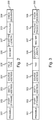
- Ethernet frame 200 traditionally contains a 7-octet preamble field 201 with pattern of alternating 1 and 0 bits allowing network devices to synchronize their receiver clocks, a 1-octet start of frame delimiter field 202 with a predetermined bit pattern allowing byte synchronization and marking a new frame, a 6-octet destination address field 203 with MAC address of the destination endpoint, a 6-octet source address field 204 with MAC address of the source endpoint, a 2-octet Ethertype or length field 207 with indication of the type of Ethernet frame or the length of the Ethernet frame, a payload section 208 of variable length ranging from 46 octets up to 1500 octets, and 4-octet frame check sequence field 209 with 32 bit long cyclic redundancy check (abbreviated CRC) sequence.
- CRC cyclic redundancy check
- Ethernet frame 200 further contains a 4-octet sequence number field consisting of a 2-octet field type code 205 and a 2-octet sequence number 206.
- a first embodiment of the sequence number insertion unit 191 hence exploits the optional 4-octet tag foreseen in the IEEE 802.3 Ethernet standard to insert immediately after the destination address and source address a 2-octet field type code 205, i.e. a predetermined 16-bit sequence that enables to distinguish the sequence number field from existing type, length and VLAN ID field types, and a 16-bit sequence number 206.
- the 16-bit sequence number is applied per Ethernet data flow such that successive frames of an atomic Ethernet data flow carry subsequent numbers, as a result of which the order of Ethernet frames or packets can be restored in any atomic Ethernet data flow based on the sequence numbers.
- Ethernet frame 300 contains a 7-octet preamble field 301 with pattern of alternating 1 and 0 bits allowing network devices to synchronize their receiver clocks, a 1-octet start of frame delimiter field 302 with a predetermined bit pattern allowing byte synchronization and marking a new frame, a 6-octet destination address field 303 with MAC address of the destination endpoint, a 6-octet source address field 304 with MAC address of the source endpoint, an optional 4-octet tag field 305, a 2-octet Ethertype or length field 306 with indication of the type of Ethernet frame or the length of the Ethernet frame, a payload section 308 of variable length ranging from 46 octets up to 1500 octets, and 4-octet frame check sequence field 309 with 32 bit long
- Ethernet frame 300 further contains a 2-octet sequence number field 307 containing a 2-octet sequence number.
- This 2-octet sequence number field 307 is inserted immediately after the Ethertype / Length field 306 that ends the Ethernet frame header.
- the 16-bit sequence number is applied per Ethernet data flow such that successive frames of an atomic Ethernet data flow carry subsequent numbers, as a result of which the order of Ethernet frames or packets can be restored in any atomic Ethernet data flow based on the sequence numbers. Insertion of a few octets in Ethernet frames or packets is not an issue in state-of-the-art packet processing logic.
- a bonding processor in the destination bonded ONU can thus be configured to interpret the sequence number field 307 correctly for re-sequencing, depending on the destination MAC identifier.
- the sequence numbered Ethernet frames or packets are demultiplexed or distributed across per-channel queues 193, 194 by demultiplexer / load balancer 192 according to some load distribution algorithm.
- the load balancer 192 distributes Ethernet frames or packets for a particular destination ONU with inserted sequence number in a more or less load balanced manner across the member wavelength channels 121-124 of the target bonding group, taking into account the length of each Ethernet frame, and possibly other parameters that determine the aggregate load on a particular channel, like the number of bonded or non-bonded ONUs served by the channel, the aggregate bandwidth on the channel, the share of bandwidth per ONU on the channel, or other.
- the load balancer 192 takes care not to assign more data destined to the same ONU consecutively on a same bonding group member channel MAC than can be transmitted in the next single timeslot on that channel for that ONU.
- Shaper 195 schedules the transmission of the Ethernet frames or packets by selecting Ethernet frames or packets from the per-channel queues 193, 194 and assigning the selected Ethernet frames or packets to the respective MAC units 161 ... 16n, 171 ... 17n for transmission thereby over the respective physical single wavelength Ethernet interfaces.
- the transceivers 111 and 112 comprise a downstream/upstream multiplexer/demultiplexer to separate downstream traffic transmitted to ONUs 103, 104 and 105 by OLT 101 from upstream traffic received from ONUs 103, 104 and 105 by OLT 101. Ethernet frames or packets received by the MAC units 161 ... 16n, 171 ...
- sequence number extraction unit 196 stores the received Ethernet frames or packets in queues 197, 198, which queue Ethernet frames or packets that either are not carried over bonded channels, and do not contain re-sequencing numbers, or Ethernet frames or packets that are carried on a particular shared media channel, in a different queue per all non-bonding traffic and optional priority, or per channel and ONU and optional priority, and the demultiplexer 199 serves the different queues 197, 198 such that the next sequence number Ethernet frame of an Ethernet flow becomes forwarded to the interworking function 114 via next sequence number comparison unit 190.
- the demultiplexer 199 and next sequence number comparison unit 190 in other words re-sequence the received Ethernet frames or packets received from bonding ONUs 105 such that any possible disorder resulting from the bonding is restored before the Ethernet frames or packets are transferred to a different communications network by interworking function 114.
- the sequence number extraction unit 196 stores the received Ethernet frames or packets from legacy ONUs 103, 104 in a separate non-bonding queue 200.
- the scheduler 201 offers access for the single non-bonded ONU queue and for the multiple bonded ONU channel queue groups to the IWF 114.
- 401 represents a sequence of subsequent timeslots 431-442 for transmission on wavelength channel 121
- 402 represents a sequence of subsequent timeslots 451-462 for transmission on wavelength channel 122
- 403 represents a sequence of subsequent timeslots 471-482 for transmission on wavelength channel 123
- 404 represents a sequence of subsequent timeslots 491-502 for transmission on wavelength channel 124.
- the timeslots in 401, 402, 403 and 404 are not aligned because of varying transmission latencies between the different channels 221-224 that form part of a bonding group.
- the transmission ONU timeslot schedulers 195, 196 at the OLT side, for both down- and upstream, of all bonding group member wavelength channel MACs, are coordinated somehow for bonded ONUs. This is illustrated in Fig. 4 by 400 which shows that timeslots for a same bonded ONU, for instance BOND ONU1, is reserved more or less simultaneously on all member wavelength channels, such that the Ethernet frames or packets transmitted to / from that bonded ONU are sent with little time difference on all concurrent same-data rate wavelength channels.
- the schedulers are configured such that transmissions to/from a first bonding ONU, BOND ONU1, take place in timeslot 431 on channel 121, in timeslot 451 on channel 122, in timeslot 471 on channel 123 and in timeslot 491 on channel 124, the timeslots 431, 451, 471 and 491 all starting within time interval 411 reserved by the schedulers for synchronized transmission to/from BOND ONU1.
- the transmissions to/from BOND ONU2, BOND ONU3, BOND ONU4 ... BOND ONUz are synchronized across the member wavelength channels of the bonding group to take place in timeslots that respectively start in time intervals 412, 413, 414 ... 417.
- Such synchronized scheduling of timeslots for bonded ONUs minimizes the need for re-sequencing queuing at the receiver side. Any propagation delay differences and data transfer contention between member wavelength channel MACs is resolved in the same process. Consecutively accessed timeslots for the same ONU and data priority on the different wavelength channels can be staggered in time to achieve an optimal timing which even compensates for delays in the transfer of data from the bonding group processor 113 to the different wavelength channel MACs participating in the dedicated bonding group for a particular ONU. A failing or repaired wavelength channel can be excluded or included automatically and very quickly by adapting the scheduler. Unused bonded ONU timeslots do not have to be wasted.
- the transmitting wavelength channel MAC timeslot scheduler detects that actually no data is available to fill the bonded ONU timeslot, it can still grant the slot to any non-bonded ONU with data waiting, as for instance illustrated in Fig. 4 where a first non-bonding ONU, named NB ONU1, uses timeslots 433, 474 and 492, and where a second non-bonding ONU, named NB ONU2, uses timeslot 476.
- Coordination of bonded ONU timeslot assignment wavelength is made possible, even across physical MAC devices, by using a simple common time reference, for instance a 1 pps clock signal, either locally generated by network synchronization unit 115, or by a network wide synchronized time setting construct, with accuracy better than the time slot scheduling granularity.
- the scheduling order of ONU timeslots can be chosen such that simultaneous scheduling of timeslots for a same ONU and data priority is achieved in a simple way, for instance by scheduling timeslots 431-437, 451-457, 471-477, 491-497 for bonded ONUs starting in time intervals 411-417 at the beginning of a subframe or superframe, followed by timeslots 438-442, 458-462, 478-482, 498-502 for the non-bonded ONUs starting in time intervals 418-421.
- any timeslots on particular wavelength channels for bonded ONUs that are not used, because not participating in the bonded access, or because insufficient data is available for transmission during that timeslot can be filled by data traffic to ONUs and data priorities not using bonded data transfer.
- the bonding ONU 105 has a bonding group processor 152 that is configured to detect or assume presence of the sequence number field in Ethernet frames or packets that are received via the plural bonded interfaces 151, and to re-sequence Ethernet frames or packets belonging to a single atomic Ethernet flow and possibly disordered as a consequence of latency variations between the different single wavelength channels 121, 122, 123, 124 over which these Ethernet frames or packets have been sent as a result of the bonding.
- an Ethernet packet is put in the re-sequencing queue corresponding to the bonding group member channel it arrived on. The queues are emptied in the order of the consecutive sequence numbers of their Head of Line packets.
- the re-sequencing queue size N per member wavelength channel, source and priority equals the maximum size of a scheduling slot multiplied by the maximum number of bonded wavelength channels, depending on the chosen distribution discipline at the transmitting bonding processor and implementation artefacts.
- the properly ordered Ethernet frames or packets are handed over to the interworking function 153 for transfer to a different communication network in case the ONU 105 forms part of a cabinet or for transfer to higher layer applications in case the ONU 105 forms part of customer premises equipment.
- the legacy ONUs 103 and 104 in parallel continue to receive Ethernet frames or packets that are transmitted using single wavelength channels 121 and 123 that are also to convey part of the bonded traffic destined for bonding ONU 105. Ethernet frames or packets destined for these legacy ONUs 103 and 104 continue to arrive in proper order as they are sent sequentially over a single wavelength channel.
- the respective MAC units 131 and 141 consequently can process these Ethernet frames or packets in the traditional way and hand-over the Ethernet frames or packets respectively to interworking functions 132 and 142 without any re-sequencing needs.
- the backwards compatible sequence numbering introduced to enable sequence restoration in bonded groups does not prevent to mix such bonded traffic with non-bonded traffic and allow deployment of bonding ONUs in a network with legacy ONUs, both types of ONUs using the same physical medium interfaces, e.g. the same optical wavelength channels in the example of a PON.
- bonded data transfer may be limited to only a sub-set of the supported data transfer priorities to a particular ONU, in order to save on hardware re-sequencing resources in the bonding processors.
- massive data transfer to a particular ONU like for instance a software update, is not required with multiple priorities at the same time.
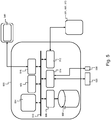
- Fig. 5 shows a suitable computing system 600 enabling to implement embodiments of the device and method for bonding according to the invention.
- Computing system 600 may in general be formed as a suitable general-purpose computer and comprise a bus 510, a processor 503, a local memory 504, one or more optional input interfaces 514, one or more optional output interfaces 516, a communication interface 512, a storage element interface 506, and one or more storage elements 508.
- Bus 510 may comprise one or more conductors that permit communication among the components of the computing system 600.
- Processor 503 may include any type of conventional processor or microprocessor that interprets and executes programming instructions.
- Local memory 504 may include a random-access memory (RAM) or another type of dynamic storage device that stores information and instructions for execution by processor 503 and/or a read only memory (ROM) or another type of static storage device that stores static information and instructions for use by processor 503.
- RAM random-access memory
- ROM read only memory
- Input interface 514 may comprise one or more conventional mechanisms that permit an operator or user to input information to the computing device 600, such as a keyboard 520, a mouse 530, a pen, voice recognition and/or biometric mechanisms, a camera, etc.
- Output interface 516 may comprise one or more conventional mechanisms that output information to the operator or user, such as a display 540, etc.
- Communication interface 512 may comprise any transceiver-like mechanism such as for example one or more interfaces that carry Ethernet frames or packets, that enables computing system 600 to communicate with other devices and/or systems, for example with other computing devices 581, 582, 583.
- the communication interface 512 of computing system 600 may be connected to such another computing system by means of a local area network (LAN) or a wide area network (WAN) such as for example the internet.
- Storage element interface 506 may comprise a storage interface such as for example a Serial Advanced Technology Attachment (SATA) interface or a Small Computer System Interface (SCSI) for connecting bus 510 to one or more storage elements 508, such as one or more local disks, for example SATA disk drives, and control the reading and writing of data to and/or from these storage elements 508.
- SATA Serial Advanced Technology Attachment
- SCSI Small Computer System Interface
- computing system 600 could thus correspond to the bonding group processors 113 or 152 in the embodiments illustrated by Fig. 1 .
- circuitry may refer to one or more or all of the following:
- circuitry also covers an implementation of merely a hardware circuit or processor (or multiple processors) or portion of a hardware circuit or processor and its (or their) accompanying software and/or firmware.
- circuitry also covers, for example and if applicable to the particular claim element, a baseband integrated circuit or processor integrated circuit for a mobile device or a similar integrated circuit in a server, a cellular network device, or other computing or network device.
- top, bottom, over, under, and the like are introduced for descriptive purposes and not necessarily to denote relative positions. It is to be understood that the terms so used are interchangeable under appropriate circumstances and embodiments of the invention are capable of operating according to the present invention in other sequences, or in orientations different from the one(s) described or illustrated above.
Landscapes
- Engineering & Computer Science (AREA)
- Computer Networks & Wireless Communication (AREA)
- Signal Processing (AREA)
- Computer Security & Cryptography (AREA)
- Data Exchanges In Wide-Area Networks (AREA)
- Small-Scale Networks (AREA)
Claims (10)
- Bondingprozessor (113) zum rückwärtskompatiblen Bonden einer Vielzahl von physischen Schnittstellen (121, 122, 123, 124), die Ethernetframes oder -pakete transportieren, zu einer einzelnen logischen Schnittstelle, die Ethernetframes oder - pakete transportiert, was eine gebondete Übertragung eines ausgewählten Ethernetdatenstroms von einem Quellnetzwerkelement (101) zu einem Zielnetzwerkelement (105) in einem Netzwerk erlaubt, wobei die physischen Schnittstellen (121, 122, 123, 124), die Ethernetframes oder -pakete transportieren, auch für eine nicht gebondete Übertragung verwendet werden, wobei der Bondingprozessor (133) Folgendes umfasst:- Mittel (191) zum Einfügen einer Sequenznummer (206; 307) in Ethernetframes oder -pakete des ausgewählten Ethernetdatenstroms, um dadurch sequenziell nummerierte Ethernetframes oder -pakete (200; 300) zu erzeugen;- Mittel (192, 193) zum Verteilen der sequenziell nummerierten Ethernetframes oder -pakete (200; 300) über die Vielzahl von physischen Schnittstellen (121, 122, 123, 124), die Ethernetframes oder -pakete transportieren, gemäß einem Lastverteilungskriterium,dadurch gekennzeichnet, dass das Lastverteilungskriterium die jeweiligen Längen der sequenziell nummerierten Ethernetframes oder -pakete (200; 300) berücksichtigt;
und der Bondingprozessor (133) ferner Folgendes umfasst:- Mittel (195) zum Reservieren von im Wesentlichen gleichzeitigen Zeitschlitzen (431, 451, 471, 491) an der Vielzahl von physischen Schnittstellen (121, 122, 123, 124), die Ethernetframes oder -pakete transportieren, für eine gebondete Übertragung von sequenziell nummerierten Ethernetframes oder - paketen (200; 300). - Bondingprozessor (113) nach Anspruch 1, wobei die Mittel (191) zum Einfügen einer Sequenznummer (307) Folgendes umfassen:- Mittel zum Einfügen eines zwei Oktette umfassenden Sequenznummernfeldes (307) hinter dem Länge/Typ-Feld (306), das das Ende des Headers der Ethernetframes oder -pakete darstellt, wobei das Sequenznummernfeld eine Sequenznummer aus zwei Oktetten umfasst, um dadurch die sequenziell nummerierten Ethernetframes oder -pakete (300) zu erzeugen, die zur Übertragung auf einer selben physischen oder logischen Ethernetschnittstelle mit nicht sequenziell nummerierten Ethernetframes oder -paketen von einem oder mehreren verschiedenen Ethernetdatenströmen gemischt werden können.
- Bondingprozessor (113) nach Anspruch 1, wobei die Mittel (191) zum Einfügen einer Sequenznummer (306) Folgendes umfassen:- Mittel zum Einfügen eines vier Oktette umfassenden Sequenznummernfeldes hinter dem Zieladressfeld (203) und dem Quelladressfeld (204) in den Ethernetframes oder -paketen in die Ethernetframes oder -pakete, wobei das Sequenznummernfeld ein zwei Oktette umfassendes Feld Typcode (205), der das Sequenznummernfeld von vorhandenen Feldtypen unterscheidet, und eine zwei Oktette umfassende Sequenznummer (206) umfasst, um dadurch die sequenziell nummerierten Ethernetframes oder -pakete (200) zu erzeugen, die zur Übertragung auf einer selben physischen oder logischen Ethernetschnittstelle mit nicht sequenziell nummerierten Ethernetframes oder -paketen von einem oder mehreren verschiedenen Ethernetdatenströmen gemischt werden können.
- Bondingprozessor (113) nach einem der vorhergehenden Ansprüche, wobei die Mittel (192, 193) zum Verteilen der sequenziell nummerierten Ethernetframes oder -pakete über die Vielzahl von physischen Ethernetschnittstellen Mittel zum Empfangen eines Rückstausignals von einer Übertragungswarteschlange einer physischen Ethernetschnittstelle, die einen Teil der Vielzahl von physischen Ethernetschnittstellen bildet, immer wenn eine Übertragung eines nächsten Datenblocks initiiert werden kann, umfassen.
- Bondingprozessor (113) nach einem der vorhergehenden Ansprüche, wobei die im Wesentlichen gleichzeitigen Zeitschlitze (431, 451, 471, 491) unter Verwendung einer gemeinsamen Zeitreferenz erzeugt und am Anfang eines Unterframes oder eines Superframes in einem passiven optischen Netzwerk unter Verwendung eines Datenschichtprotokolls, das mit dem vorhandenen Datenschichtprotokoll des passiven optischen Netzwerks rückwärtskompatibel ist, wie durch ITU-T und IEEE standardisiert, geplant wird.
- Bondingprozessor (113) nach einem der vorhergehenden Ansprüche, wobei die gebondete Übertragung auf einen Untersatz von Datenübermittlungsprioritäten beschränkt ist.
- Ethernetframeempfänger (101; 105) zum Empfangen von Ethernetframes oder -paketen von einem oder mehreren Ethernetdatenströmen, wobei der Ethernetframeempfänger (101; 105) Folgendes umfasst:- Mittel (111, 112; 151) zum Empfangen von Ethernetframes oder -paketen, die auf einer selben physischen oder logischen Ethernetschnittstelle übertragen werden;- Mittel (196; 152) zum Detektieren eines Sequenznummernfeldes (206; 307) in den Ethernetframes oder - paketen, wobei das Sequenznummernfeld (206; 307) eine Sequenznummer umfasst;- Mittel (196; 152) zum Unterscheiden von sequenziell nummerierten Ethernetframes oder -paketen eines gebondeten Ethernetdatenstroms von nicht sequenziell nummerierten Ethernetframes oder -paketen von einem oder mehreren anderen Ethernetdatenströmen auf Basis der Zieladresse oder der Quelladresse oder des Vorhandenseins des Sequenznummernfeldes;- Mittel (197, 198, 199, 190; 152) zum Neusequenzieren von empfangenen sequenziell nummerierten Ethernetframes oder - paketen des gebondeten Ethernetdatenstroms, der eine Neusequenzierungswarteschlange (197, 198) pro physischer Schnittstelle umfasst, die Ethernetframes oder -pakete transportiert, deren Head-of-Line-Pakete auf Basis der Sequenznummer ausgewählt werden,dadurch gekennzeichnet, dass die Mittel zum Neusequenzieren (197, 198, 199, 190) dazu ausgelegt sind, das Paket, das mit einer fehlenden Sequenznummer verknüpft ist, als verloren zu betrachten, wenn jede Neusequenzierungswarteschlange ein Head-of-Line-Paket aufweist.
- Ethernetframeempfänger (101, 105) nach Anspruch 7, wobei die Mittel zum Neusequenzieren (197, 198, 199, 190) dazu ausgelegt sind, eine vorbestimmte Zeit auf die Ankunft eines Pakets mit einer fehlenden Sequenznummer zu warten, wenn eine oder mehrere Neusequenzierungswarteschlangen leer sind.
- Bondingverfahren zum rückwärtskompatiblen Bonden einer Vielzahl von physischen Schnittstellen (121, 122, 123, 124), die Ethernetframes oder -pakete transportieren, durch einen Bondingprozessor (113) zu einer einzelnen logischen Schnittstelle, die Ethernetframes oder -pakete transportiert, was eine gebondete Übertragung eines ausgewählten Ethernetdatenstroms von einem Quellnetzwerkelement (101) zu einem Zielnetzwerkelement (105) in einem Netzwerk erlaubt, wobei die physischen Schnittstellen (121, 122, 123, 124), die Ethernetframes oder -pakete transportieren, auch für eine nicht gebondete Übertragung verwendet werden, wobei das Bondingverfahren Folgendes umfasst:- Einfügen einer Sequenznummer in Ethernetframes oder - pakete des ausgewählten Ethernetdatenstroms, um dadurch sequenziell nummerierte Ethernetframes oder -pakete (200; 300) zu erzeugen;- Verteilen der sequenziell nummerierten Ethernetframes oder -pakete (200; 300) über die Vielzahl von physischen Schnittstellen (121, 122, 123, 124), die Ethernetframes oder - pakete transportieren, gemäß einem Lastverteilungskriterium,dadurch gekennzeichnet, dass das Lastverteilungskriterium die jeweiligen Längen der sequenziell nummerierten Ethernetframes oder -pakete (200; 300) berücksichtigt;
und das Bondingverfahren ferner Folgendes umfasst:- Reservieren von im Wesentlichen gleichzeitigen Zeitschlitzen (431, 451, 471, 491) an der Vielzahl von physischen Schnittstellen (121, 122, 123, 124), die Ethernetframes oder -pakete transportieren, für eine gebondete Übertragung von sequenziell nummerierten Ethernetframes oder - paketen (200; 300). - Verfahren zum Empfangen von Ethernetframes oder - paketen von einem oder mehreren Ethernetdatenströmen durch einen Ethernetframeempfänger (101; 105), wobei das Verfahren Folgendes umfasst:- Empfangen von Ethernetframes oder -paketen, die auf einer selben physischen oder logischen Schnittstelle, die Ethernetframes oder -pakete transportiert, übertragen werden;- Detektieren eines Sequenznummernfeldes (206; 307) in den Ethernetframes oder -paketen, wobei das Sequenznummernfeld (206; 307) eine Sequenznummer umfasst;- Unterscheiden von sequenziell nummerierten Ethernetframes oder -paketen (200; 300) eines gebondeten Ethernetdatenstroms von nicht sequenziell nummerierten Ethernetframes oder -paketen von einem oder mehreren nicht gebondeten Ethernetdatenströmen auf Basis der Zieladresse oder der Quelladresse oder des Vorhandenseins des Sequenznummernfeldes (206; 307);- Neusequenzieren von empfangenen sequenziell nummerierten Ethernetframes oder -paketen (200; 300) des gebondeten Ethernetdatenstroms durch Speichern der sequenziell nummerierten Ethernetframes oder -pakete (200; 300) in Neusequenzierungswarteschlangen (197, 198) pro physischer Schnittstelle, die Ethernetframes oder -pakete transportiert, und Auswählen der Head-of-Line-Pakete aus den Neusequenzierungswarteschlangen (197, 198) auf Basis der Sequenznummer,dadurch gekennzeichnet, dass das Verfahren das Betrachten des Pakets, das mit einer fehlenden Sequenznummer verknüpft ist, als verloren, wenn jede Neusequenzierungswarteschlange ein Head-of-Line-Paket aufweist, umfasst.
Priority Applications (1)
| Application Number | Priority Date | Filing Date | Title |
|---|---|---|---|
| EP18187834.9A EP3609141B1 (de) | 2018-08-07 | 2018-08-07 | Ethernet-bonding-prozessor und entsprechender ethernet frame empfänger |
Applications Claiming Priority (1)
| Application Number | Priority Date | Filing Date | Title |
|---|---|---|---|
| EP18187834.9A EP3609141B1 (de) | 2018-08-07 | 2018-08-07 | Ethernet-bonding-prozessor und entsprechender ethernet frame empfänger |
Publications (2)
| Publication Number | Publication Date |
|---|---|
| EP3609141A1 EP3609141A1 (de) | 2020-02-12 |
| EP3609141B1 true EP3609141B1 (de) | 2021-04-21 |
Family
ID=63174006
Family Applications (1)
| Application Number | Title | Priority Date | Filing Date |
|---|---|---|---|
| EP18187834.9A Active EP3609141B1 (de) | 2018-08-07 | 2018-08-07 | Ethernet-bonding-prozessor und entsprechender ethernet frame empfänger |
Country Status (1)
| Country | Link |
|---|---|
| EP (1) | EP3609141B1 (de) |
Family Cites Families (2)
| Publication number | Priority date | Publication date | Assignee | Title |
|---|---|---|---|---|
| WO2006020559A2 (en) * | 2004-08-09 | 2006-02-23 | Arris International, Inc. | Very high speed cable modem for increasing bandwidth |
| US10230654B2 (en) * | 2016-12-28 | 2019-03-12 | Intel IP Corporation | Multiband aggregation data encapsulation |
-
2018
- 2018-08-07 EP EP18187834.9A patent/EP3609141B1/de active Active
Non-Patent Citations (1)
| Title |
|---|
| None * |
Also Published As
| Publication number | Publication date |
|---|---|
| EP3609141A1 (de) | 2020-02-12 |
Similar Documents
| Publication | Publication Date | Title |
|---|---|---|
| CN113972997B (zh) | 一种传输数据的方法和设备 | |
| US10397674B2 (en) | PON wavelength bonding for providing higher-rate data services | |
| US6735219B1 (en) | Packet-processing apparatus and packet switch adapter for the processing of variable-length packets and a method thereof | |
| US9967638B2 (en) | Optical switching | |
| US9276870B2 (en) | Switching node with load balancing of bursts of packets | |
| CN1929361B (zh) | 传输装置 | |
| CN101027862B (zh) | 对通信流量分级的多信道通信 | |
| EP2378721B1 (de) | Bandbreitenzuweisungsverfahren und routing-vorrichtung | |
| CN108243120A (zh) | 基于灵活以太网的业务流传输方法、装置和通信系统 | |
| US20020191588A1 (en) | Integrated circuit and packet switching system | |
| US20040052274A1 (en) | Method and apparatus for allocating bandwidth on a passive optical network | |
| EP3384681B1 (de) | Pon-wellenlängen-bonding für hochratige dienste | |
| EP0810808B1 (de) | Einrichtung zur Übertragung von ATM-Zellen | |
| US7577129B2 (en) | Supporting multiple logical channels in a physical interface | |
| KR101388530B1 (ko) | 이동통신 시스템의 링크 이중화 장치 및 방법 | |
| WO2019205136A1 (zh) | 报文处理方法及设备 | |
| US20100158036A1 (en) | Method and apparatus of receiving burst data using multiple upstream channels based on upstream bandwidth allocation information in hfc network | |
| EP3446490B1 (de) | Pon-wellenlängenbonding zur bereitstellung von datendiensten mit höherer rate | |
| EP3609141A1 (de) | Ethernet-bonding-prozessor und entsprechender ethernet frame empfänger | |
| EP3609144A1 (de) | Ethernet-rahmenprozessor und -empfänger | |
| US8077739B2 (en) | Methods, communication networks, and computer program products for communicating time division multiplexing traffic using a traffic encapsulation standard configured to support statistical multiplexing (STATMUX) traffic | |
| KR100503417B1 (ko) | 이더넷 수동형 광 네트워크에서의 QoS 보장형 스케쥴링시스템 및 방법 | |
| CN119449920B (zh) | 一种报文处理方法、装置、光线路终端及存储介质 | |
| US20070025385A1 (en) | Residential ethernet node device for transmitting synchronous data using counter and synchronous data transmitting method thereof | |
| KR20190117970A (ko) | 포토닉 프레임 처리 장치 및 방법 |
Legal Events
| Date | Code | Title | Description |
|---|---|---|---|
| PUAI | Public reference made under article 153(3) epc to a published international application that has entered the european phase |
Free format text: ORIGINAL CODE: 0009012 |
|
| STAA | Information on the status of an ep patent application or granted ep patent |
Free format text: STATUS: THE APPLICATION HAS BEEN PUBLISHED |
|
| AK | Designated contracting states |
Kind code of ref document: A1 Designated state(s): AL AT BE BG CH CY CZ DE DK EE ES FI FR GB GR HR HU IE IS IT LI LT LU LV MC MK MT NL NO PL PT RO RS SE SI SK SM TR |
|
| AX | Request for extension of the european patent |
Extension state: BA ME |
|
| STAA | Information on the status of an ep patent application or granted ep patent |
Free format text: STATUS: REQUEST FOR EXAMINATION WAS MADE |
|
| 17P | Request for examination filed |
Effective date: 20200812 |
|
| RBV | Designated contracting states (corrected) |
Designated state(s): AL AT BE BG CH CY CZ DE DK EE ES FI FR GB GR HR HU IE IS IT LI LT LU LV MC MK MT NL NO PL PT RO RS SE SI SK SM TR |
|
| GRAP | Despatch of communication of intention to grant a patent |
Free format text: ORIGINAL CODE: EPIDOSNIGR1 |
|
| STAA | Information on the status of an ep patent application or granted ep patent |
Free format text: STATUS: GRANT OF PATENT IS INTENDED |
|
| INTG | Intention to grant announced |
Effective date: 20201214 |
|
| GRAS | Grant fee paid |
Free format text: ORIGINAL CODE: EPIDOSNIGR3 |
|
| GRAA | (expected) grant |
Free format text: ORIGINAL CODE: 0009210 |
|
| STAA | Information on the status of an ep patent application or granted ep patent |
Free format text: STATUS: THE PATENT HAS BEEN GRANTED |
|
| AK | Designated contracting states |
Kind code of ref document: B1 Designated state(s): AL AT BE BG CH CY CZ DE DK EE ES FI FR GB GR HR HU IE IS IT LI LT LU LV MC MK MT NL NO PL PT RO RS SE SI SK SM TR |
|
| REG | Reference to a national code |
Ref country code: GB Ref legal event code: FG4D |
|
| REG | Reference to a national code |
Ref country code: CH Ref legal event code: EP |
|
| REG | Reference to a national code |
Ref country code: DE Ref legal event code: R096 Ref document number: 602018015753 Country of ref document: DE Ref country code: IE Ref legal event code: FG4D |
|
| REG | Reference to a national code |
Ref country code: AT Ref legal event code: REF Ref document number: 1385801 Country of ref document: AT Kind code of ref document: T Effective date: 20210515 |
|
| REG | Reference to a national code |
Ref country code: LT Ref legal event code: MG9D |
|
| REG | Reference to a national code |
Ref country code: AT Ref legal event code: MK05 Ref document number: 1385801 Country of ref document: AT Kind code of ref document: T Effective date: 20210421 |
|
| REG | Reference to a national code |
Ref country code: NL Ref legal event code: MP Effective date: 20210421 |
|
| PG25 | Lapsed in a contracting state [announced via postgrant information from national office to epo] |
Ref country code: LT Free format text: LAPSE BECAUSE OF FAILURE TO SUBMIT A TRANSLATION OF THE DESCRIPTION OR TO PAY THE FEE WITHIN THE PRESCRIBED TIME-LIMIT Effective date: 20210421 Ref country code: HR Free format text: LAPSE BECAUSE OF FAILURE TO SUBMIT A TRANSLATION OF THE DESCRIPTION OR TO PAY THE FEE WITHIN THE PRESCRIBED TIME-LIMIT Effective date: 20210421 Ref country code: FI Free format text: LAPSE BECAUSE OF FAILURE TO SUBMIT A TRANSLATION OF THE DESCRIPTION OR TO PAY THE FEE WITHIN THE PRESCRIBED TIME-LIMIT Effective date: 20210421 Ref country code: BG Free format text: LAPSE BECAUSE OF FAILURE TO SUBMIT A TRANSLATION OF THE DESCRIPTION OR TO PAY THE FEE WITHIN THE PRESCRIBED TIME-LIMIT Effective date: 20210721 Ref country code: AT Free format text: LAPSE BECAUSE OF FAILURE TO SUBMIT A TRANSLATION OF THE DESCRIPTION OR TO PAY THE FEE WITHIN THE PRESCRIBED TIME-LIMIT Effective date: 20210421 Ref country code: NL Free format text: LAPSE BECAUSE OF FAILURE TO SUBMIT A TRANSLATION OF THE DESCRIPTION OR TO PAY THE FEE WITHIN THE PRESCRIBED TIME-LIMIT Effective date: 20210421 |
|
| REG | Reference to a national code |
Ref country code: DE Ref legal event code: R079 Ref document number: 602018015753 Country of ref document: DE Free format text: PREVIOUS MAIN CLASS: H04L0012709000 Ipc: H04L0045243000 |
|
| PG25 | Lapsed in a contracting state [announced via postgrant information from national office to epo] |
Ref country code: RS Free format text: LAPSE BECAUSE OF FAILURE TO SUBMIT A TRANSLATION OF THE DESCRIPTION OR TO PAY THE FEE WITHIN THE PRESCRIBED TIME-LIMIT Effective date: 20210421 Ref country code: SE Free format text: LAPSE BECAUSE OF FAILURE TO SUBMIT A TRANSLATION OF THE DESCRIPTION OR TO PAY THE FEE WITHIN THE PRESCRIBED TIME-LIMIT Effective date: 20210421 Ref country code: PT Free format text: LAPSE BECAUSE OF FAILURE TO SUBMIT A TRANSLATION OF THE DESCRIPTION OR TO PAY THE FEE WITHIN THE PRESCRIBED TIME-LIMIT Effective date: 20210823 Ref country code: LV Free format text: LAPSE BECAUSE OF FAILURE TO SUBMIT A TRANSLATION OF THE DESCRIPTION OR TO PAY THE FEE WITHIN THE PRESCRIBED TIME-LIMIT Effective date: 20210421 Ref country code: NO Free format text: LAPSE BECAUSE OF FAILURE TO SUBMIT A TRANSLATION OF THE DESCRIPTION OR TO PAY THE FEE WITHIN THE PRESCRIBED TIME-LIMIT Effective date: 20210721 Ref country code: PL Free format text: LAPSE BECAUSE OF FAILURE TO SUBMIT A TRANSLATION OF THE DESCRIPTION OR TO PAY THE FEE WITHIN THE PRESCRIBED TIME-LIMIT Effective date: 20210421 Ref country code: GR Free format text: LAPSE BECAUSE OF FAILURE TO SUBMIT A TRANSLATION OF THE DESCRIPTION OR TO PAY THE FEE WITHIN THE PRESCRIBED TIME-LIMIT Effective date: 20210722 Ref country code: IS Free format text: LAPSE BECAUSE OF FAILURE TO SUBMIT A TRANSLATION OF THE DESCRIPTION OR TO PAY THE FEE WITHIN THE PRESCRIBED TIME-LIMIT Effective date: 20210821 |
|
| REG | Reference to a national code |
Ref country code: DE Ref legal event code: R097 Ref document number: 602018015753 Country of ref document: DE |
|
| PG25 | Lapsed in a contracting state [announced via postgrant information from national office to epo] |
Ref country code: RO Free format text: LAPSE BECAUSE OF FAILURE TO SUBMIT A TRANSLATION OF THE DESCRIPTION OR TO PAY THE FEE WITHIN THE PRESCRIBED TIME-LIMIT Effective date: 20210421 Ref country code: CZ Free format text: LAPSE BECAUSE OF FAILURE TO SUBMIT A TRANSLATION OF THE DESCRIPTION OR TO PAY THE FEE WITHIN THE PRESCRIBED TIME-LIMIT Effective date: 20210421 Ref country code: DK Free format text: LAPSE BECAUSE OF FAILURE TO SUBMIT A TRANSLATION OF THE DESCRIPTION OR TO PAY THE FEE WITHIN THE PRESCRIBED TIME-LIMIT Effective date: 20210421 Ref country code: ES Free format text: LAPSE BECAUSE OF FAILURE TO SUBMIT A TRANSLATION OF THE DESCRIPTION OR TO PAY THE FEE WITHIN THE PRESCRIBED TIME-LIMIT Effective date: 20210421 Ref country code: EE Free format text: LAPSE BECAUSE OF FAILURE TO SUBMIT A TRANSLATION OF THE DESCRIPTION OR TO PAY THE FEE WITHIN THE PRESCRIBED TIME-LIMIT Effective date: 20210421 Ref country code: SK Free format text: LAPSE BECAUSE OF FAILURE TO SUBMIT A TRANSLATION OF THE DESCRIPTION OR TO PAY THE FEE WITHIN THE PRESCRIBED TIME-LIMIT Effective date: 20210421 Ref country code: SM Free format text: LAPSE BECAUSE OF FAILURE TO SUBMIT A TRANSLATION OF THE DESCRIPTION OR TO PAY THE FEE WITHIN THE PRESCRIBED TIME-LIMIT Effective date: 20210421 |
|
| PLBE | No opposition filed within time limit |
Free format text: ORIGINAL CODE: 0009261 |
|
| STAA | Information on the status of an ep patent application or granted ep patent |
Free format text: STATUS: NO OPPOSITION FILED WITHIN TIME LIMIT |
|
| 26N | No opposition filed |
Effective date: 20220124 |
|
| REG | Reference to a national code |
Ref country code: CH Ref legal event code: PL |
|
| PG25 | Lapsed in a contracting state [announced via postgrant information from national office to epo] |
Ref country code: MC Free format text: LAPSE BECAUSE OF FAILURE TO SUBMIT A TRANSLATION OF THE DESCRIPTION OR TO PAY THE FEE WITHIN THE PRESCRIBED TIME-LIMIT Effective date: 20210421 |
|
| REG | Reference to a national code |
Ref country code: BE Ref legal event code: MM Effective date: 20210831 |
|
| PG25 | Lapsed in a contracting state [announced via postgrant information from national office to epo] |
Ref country code: LI Free format text: LAPSE BECAUSE OF NON-PAYMENT OF DUE FEES Effective date: 20210831 Ref country code: CH Free format text: LAPSE BECAUSE OF NON-PAYMENT OF DUE FEES Effective date: 20210831 |
|
| PG25 | Lapsed in a contracting state [announced via postgrant information from national office to epo] |
Ref country code: IS Free format text: LAPSE BECAUSE OF FAILURE TO SUBMIT A TRANSLATION OF THE DESCRIPTION OR TO PAY THE FEE WITHIN THE PRESCRIBED TIME-LIMIT Effective date: 20210821 Ref country code: LU Free format text: LAPSE BECAUSE OF NON-PAYMENT OF DUE FEES Effective date: 20210807 Ref country code: AL Free format text: LAPSE BECAUSE OF FAILURE TO SUBMIT A TRANSLATION OF THE DESCRIPTION OR TO PAY THE FEE WITHIN THE PRESCRIBED TIME-LIMIT Effective date: 20210421 |
|
| PG25 | Lapsed in a contracting state [announced via postgrant information from national office to epo] |
Ref country code: IT Free format text: LAPSE BECAUSE OF FAILURE TO SUBMIT A TRANSLATION OF THE DESCRIPTION OR TO PAY THE FEE WITHIN THE PRESCRIBED TIME-LIMIT Effective date: 20210421 Ref country code: IE Free format text: LAPSE BECAUSE OF NON-PAYMENT OF DUE FEES Effective date: 20210807 Ref country code: FR Free format text: LAPSE BECAUSE OF NON-PAYMENT OF DUE FEES Effective date: 20210831 Ref country code: BE Free format text: LAPSE BECAUSE OF NON-PAYMENT OF DUE FEES Effective date: 20210831 |
|
| PG25 | Lapsed in a contracting state [announced via postgrant information from national office to epo] |
Ref country code: CY Free format text: LAPSE BECAUSE OF FAILURE TO SUBMIT A TRANSLATION OF THE DESCRIPTION OR TO PAY THE FEE WITHIN THE PRESCRIBED TIME-LIMIT Effective date: 20210421 |
|
| PG25 | Lapsed in a contracting state [announced via postgrant information from national office to epo] |
Ref country code: HU Free format text: LAPSE BECAUSE OF FAILURE TO SUBMIT A TRANSLATION OF THE DESCRIPTION OR TO PAY THE FEE WITHIN THE PRESCRIBED TIME-LIMIT; INVALID AB INITIO Effective date: 20180807 |
|
| PG25 | Lapsed in a contracting state [announced via postgrant information from national office to epo] |
Ref country code: MK Free format text: LAPSE BECAUSE OF FAILURE TO SUBMIT A TRANSLATION OF THE DESCRIPTION OR TO PAY THE FEE WITHIN THE PRESCRIBED TIME-LIMIT Effective date: 20210421 |
|
| PG25 | Lapsed in a contracting state [announced via postgrant information from national office to epo] |
Ref country code: MT Free format text: LAPSE BECAUSE OF FAILURE TO SUBMIT A TRANSLATION OF THE DESCRIPTION OR TO PAY THE FEE WITHIN THE PRESCRIBED TIME-LIMIT Effective date: 20210421 |
|
| PGFP | Annual fee paid to national office [announced via postgrant information from national office to epo] |
Ref country code: DE Payment date: 20250702 Year of fee payment: 8 |
|
| PGFP | Annual fee paid to national office [announced via postgrant information from national office to epo] |
Ref country code: GB Payment date: 20250703 Year of fee payment: 8 |
|
| PG25 | Lapsed in a contracting state [announced via postgrant information from national office to epo] |
Ref country code: TR Free format text: LAPSE BECAUSE OF FAILURE TO SUBMIT A TRANSLATION OF THE DESCRIPTION OR TO PAY THE FEE WITHIN THE PRESCRIBED TIME-LIMIT Effective date: 20210421 |