EP3609134A1 - Bgp anycast cluster service quality detection method and detection apparatus - Google Patents
Bgp anycast cluster service quality detection method and detection apparatus Download PDFInfo
- Publication number
- EP3609134A1 EP3609134A1 EP18915781.1A EP18915781A EP3609134A1 EP 3609134 A1 EP3609134 A1 EP 3609134A1 EP 18915781 A EP18915781 A EP 18915781A EP 3609134 A1 EP3609134 A1 EP 3609134A1
- Authority
- EP
- European Patent Office
- Prior art keywords
- detection
- bgp
- address
- request information
- entity server
- Prior art date
- Legal status (The legal status is an assumption and is not a legal conclusion. Google has not performed a legal analysis and makes no representation as to the accuracy of the status listed.)
- Granted
Links
- 238000001514 detection method Methods 0.000 title claims abstract description 182
- 230000004044 response Effects 0.000 claims abstract description 54
- 238000000034 method Methods 0.000 claims abstract description 41
- 238000012545 processing Methods 0.000 claims description 7
- 238000010586 diagram Methods 0.000 description 6
- 238000004891 communication Methods 0.000 description 2
- 238000012517 data analytics Methods 0.000 description 2
- 230000000694 effects Effects 0.000 description 2
- 238000005516 engineering process Methods 0.000 description 2
- 238000012986 modification Methods 0.000 description 2
- 230000004048 modification Effects 0.000 description 2
- 238000012360 testing method Methods 0.000 description 2
- 230000005856 abnormality Effects 0.000 description 1
- FFBHFFJDDLITSX-UHFFFAOYSA-N benzyl N-[2-hydroxy-4-(3-oxomorpholin-4-yl)phenyl]carbamate Chemical compound OC1=C(NC(=O)OCC2=CC=CC=C2)C=CC(=C1)N1CCOCC1=O FFBHFFJDDLITSX-UHFFFAOYSA-N 0.000 description 1
- 230000005540 biological transmission Effects 0.000 description 1
- 238000004590 computer program Methods 0.000 description 1
- 239000000284 extract Substances 0.000 description 1
- 230000006870 function Effects 0.000 description 1
- 230000000977 initiatory effect Effects 0.000 description 1
- 230000003993 interaction Effects 0.000 description 1
- 230000008569 process Effects 0.000 description 1
Images


Classifications
-
- H—ELECTRICITY
- H04—ELECTRIC COMMUNICATION TECHNIQUE
- H04L—TRANSMISSION OF DIGITAL INFORMATION, e.g. TELEGRAPHIC COMMUNICATION
- H04L41/00—Arrangements for maintenance, administration or management of data switching networks, e.g. of packet switching networks
- H04L41/50—Network service management, e.g. ensuring proper service fulfilment according to agreements
- H04L41/5032—Generating service level reports
-
- H—ELECTRICITY
- H04—ELECTRIC COMMUNICATION TECHNIQUE
- H04L—TRANSMISSION OF DIGITAL INFORMATION, e.g. TELEGRAPHIC COMMUNICATION
- H04L43/00—Arrangements for monitoring or testing data switching networks
-
- H—ELECTRICITY
- H04—ELECTRIC COMMUNICATION TECHNIQUE
- H04L—TRANSMISSION OF DIGITAL INFORMATION, e.g. TELEGRAPHIC COMMUNICATION
- H04L12/00—Data switching networks
- H04L12/28—Data switching networks characterised by path configuration, e.g. LAN [Local Area Networks] or WAN [Wide Area Networks]
- H04L12/2854—Wide area networks, e.g. public data networks
- H04L12/2856—Access arrangements, e.g. Internet access
- H04L12/2858—Access network architectures
-
- H—ELECTRICITY
- H04—ELECTRIC COMMUNICATION TECHNIQUE
- H04L—TRANSMISSION OF DIGITAL INFORMATION, e.g. TELEGRAPHIC COMMUNICATION
- H04L41/00—Arrangements for maintenance, administration or management of data switching networks, e.g. of packet switching networks
- H04L41/50—Network service management, e.g. ensuring proper service fulfilment according to agreements
- H04L41/5003—Managing SLA; Interaction between SLA and QoS
- H04L41/5009—Determining service level performance parameters or violations of service level contracts, e.g. violations of agreed response time or mean time between failures [MTBF]
-
- H—ELECTRICITY
- H04—ELECTRIC COMMUNICATION TECHNIQUE
- H04L—TRANSMISSION OF DIGITAL INFORMATION, e.g. TELEGRAPHIC COMMUNICATION
- H04L41/00—Arrangements for maintenance, administration or management of data switching networks, e.g. of packet switching networks
- H04L41/50—Network service management, e.g. ensuring proper service fulfilment according to agreements
- H04L41/5003—Managing SLA; Interaction between SLA and QoS
- H04L41/5019—Ensuring fulfilment of SLA
-
- H—ELECTRICITY
- H04—ELECTRIC COMMUNICATION TECHNIQUE
- H04L—TRANSMISSION OF DIGITAL INFORMATION, e.g. TELEGRAPHIC COMMUNICATION
- H04L43/00—Arrangements for monitoring or testing data switching networks
- H04L43/50—Testing arrangements
- H04L43/55—Testing of service level quality, e.g. simulating service usage
-
- H—ELECTRICITY
- H04—ELECTRIC COMMUNICATION TECHNIQUE
- H04L—TRANSMISSION OF DIGITAL INFORMATION, e.g. TELEGRAPHIC COMMUNICATION
- H04L45/00—Routing or path finding of packets in data switching networks
- H04L45/02—Topology update or discovery
- H04L45/04—Interdomain routing, e.g. hierarchical routing
-
- H—ELECTRICITY
- H04—ELECTRIC COMMUNICATION TECHNIQUE
- H04L—TRANSMISSION OF DIGITAL INFORMATION, e.g. TELEGRAPHIC COMMUNICATION
- H04L61/00—Network arrangements, protocols or services for addressing or naming
- H04L61/45—Network directories; Name-to-address mapping
- H04L61/4505—Network directories; Name-to-address mapping using standardised directories; using standardised directory access protocols
- H04L61/4511—Network directories; Name-to-address mapping using standardised directories; using standardised directory access protocols using domain name system [DNS]
Definitions
- the present disclosure relates to the field of network technologies and, in particular, to a detection method and a detection device for detecting quality of service (QoS) of a Border Gateway Protocol (BGP) anycast cluster.
- QoS quality of service
- BGP Border Gateway Protocol
- BGP is a routing protocol of an autonomous system running on the Transmission Control Protocol (TCP).
- TCP Transmission Control Protocol
- Anycast is a group of servers that provide a specific service through an anycast address on an Internet Protocol (IP) network.
- IP Internet Protocol
- DNS Domain Name System
- a message accesses the address can be routed by the IP network to any of the servers in the target group.
- Anycast can provide a stateless and best-effort service.
- BGP anycast uses the same IP address for different servers. Specifically, multiple servers use anycast technology to provide external services using an anycast address, that is, BGP anycast cluster service.
- BGP anycast At present, more and more service providers use BGP anycast to provide services.
- AS autonomous system
- BGP route selection short autonomous system (AS) paths are selected as optimal paths, thereby optimizing access speed.
- AS autonomous system
- the target IP has only one BGP anycast address, because it cannot be accurately determined which entity server the client specifically accesses, it is difficult to accurately handle the abnormality of the server.
- uncertainties of the route selection causes difficulties to monitor the QoS of the BGP anycast cluster.
- Embodiments of the present disclosure provide a detection method and a detection device for detecting QoS of a BGP anycast cluster, which are used to accurately collect the detection index data of the entity server in the BGP anycast cluster to improve the QoS of the BGP anycast cluster.
- embodiments of the present disclosure provide a method for detecting the QoS of a BGP anycast cluster, which is implemented in a detection device for the QoS of the BGP anycast cluster, and the method includes that:
- the detection-request information includes http protocol detection-request information.
- the detection-request information includes DNS protocol detection-request information.
- the detection index data further includes a status code and a response time of the entity server.
- the method further includes that: the detection index data is analyzed to obtain the QoS data of the entity server in the BGP anycast cluster.
- embodiments of the present disclosure provide a detection device for detecting QoS of a BGP anycast cluster.
- the detection device includes:
- the detection-request information includes http protocol detection-request information.
- the detection-request information includes DNS protocol detection-request information.
- the detection index data further includes a status code and a response time of the entity server.
- an analyzing module is included and the analyzing module is configured to analyze the detection index data to obtain the QoS data of the entity server in the BGP anycast cluster.
- each entity server in the BGP anycast cluster can be detected by arranging multiple detection devices in the BGP anycast cluster network.
- the detection device After receiving the detection task of the QoS of the BGP anycast cluster, the detection device sends a detection-request information to the BGP anycast IP address to execute the detection task, where the detection-request information is received by an entity server in the BGP anycast cluster that has a shortest AS path from the detection device. Then, the entity server in the BGP anycast cluster sends the detection-response information to the detection device, where the detection-response information includes an IP address of the entity server.
- the detection device can generate the detection index data according to the sent detection-request information and the received detection-response information, where the detection index data includes the BGP anycast IP address and the IP address of the entity server. If the entity server fails, the failed server can be quickly found through the entity server IP. Therefore, the technical solutions provided by embodiments of the present disclosure can accurately collect the detection index data of the entity server in the BGP anycast cluster, thereby improving the QoS of the BGP anycast cluster.
- FIG. 1 is a flowchart of a method for detecting quality of service (QoS) of a BGP anycast cluster according to a first method embodiment of the present disclosure.
- the method in the present embodiment of the present disclosure is implemented to a detection device for detecting the QoS of the BGP anycast cluster.
- a quantity of detection devices may be multiple, and the detection devices are distributed in the BGP anycast cluster network.
- the method according to embodiments of the present disclosure may include the following content.
- the detection device receives detection-task information for detecting the QoS of the BGP anycast cluster, where the detection-task information includes a BGP anycast IP address.
- the detection task may be set according to different requirements of the QoS of the BGP anycast cluster in different application scenarios.
- the detection-task information may be a task instruction sent by a detection-task management personnel to the detection device through other network devices, or may be a task instruction input by the detection-task management personnel through a human-computer interaction interface of the detection device.
- the detection device may be a surveillance device.
- the detection device sends detection-request information to the BGP anycast IP address, where the detection-request information is received by an entity server in the BGP anycast cluster that has a shortest AS path from the detection device.
- the http protocol detection-request information GET http://www.wangsu.com/ is used, where www.wangsu.com is a test domain name to detection.
- the IP address comes out after analysis is 1.1.1.1, which is the BGP anycast IP address.
- the detection device selects the entity server with the shortest AS path from the detection device to receive.
- the detection device receives a detection-response information sent by the entity server in the BGP anycast cluster, where the detection-response information includes an IP address of the entity server.
- the detection device sends a detection-request information to the BGP anycast IP address. After receiving the detection-request information, the entity server that provides the service writes the actual IP address thereof into the response content.
- the detection device generates detection index data according to the sent detection-request information and the received detection-response information, where the detection index data includes the BGP anycast IP address and the IP address of the entity server.
- the detection device After receiving the detection-response information, the detection device can accurately obtain the IP address of the detected entity server, and thus can accurately correlate the detected index data with the entity server IP and anycast IP.
- the detected index data may also include a status code and a response time of the entity server.
- each entity server in the BGP anycast cluster can be detected by arranging multiple detection devices in the BGP anycast cluster network.
- the detection device After receiving the detection task of the QoS of the BGP anycast cluster, the detection device sends a detection-request information to the BGP anycast IP address to execute the detection task, where the detection-request information is received by an entity server in the BGP anycast cluster that has a shortest AS path from the detection device.
- the entity server in the BGP anycast cluster sends the detection-response information to the detection device, where the detection-response information includes an IP address of the entity server.
- the detection device can generate the detection index data according to the sent detection-request information and the received detection-response information, where the detection index data includes the BGP anycast IP address and the IP address of the entity server. If the entity server fails, the failed server can be quickly found through the entity server IP. Therefore, the technical solutions provided by embodiments of the present disclosure can accurately collect the detection index data of the entity server in the BGP anycast cluster, thereby improving the QoS of the BGP anycast cluster.
- FIG. 2 is a flowchart of a method for detecting QoS of a BGP anycast cluster according to a second method embodiment of the present disclosure.
- the method in present embodiment may further include the following content.
- the detection index data is analyzed to obtain the QoS data of the entity server in the BGP anycast cluster.
- the service status of the entity server in the entire BGP anycast cluster can be obtained by big data analytics.
- FIG. 3 is a flowchart of a method for detecting QoS of a BGP anycast cluster according to a third method embodiment of the present disclosure.
- the detection device is a surveillance device
- the detection-request information is an http protocol detection-request information.
- an initiated detection-request information is: GET http://www.wangsu.com/ (www.wangsu.com is the test domain name for detecting, and the resolved IP is 1.1.1.1).
- the surveillance device 1 selects a node with the shortest AS path from the surveillance device 1, which is assumed to be the server in Moscow (of which the entity server IP is 3.3.3.3), in process 1 in FIG. 3 .
- the entity server with the IP address 3.3.3.3 writes its own physical IP 3.3.3.3 to the response content, and responds to the surveillance device 1 (IP: 1.2.3.4), in process 2 in FIG. 3 .
- the surveillance device 1 When receiving the response from the server (IP 3.3.3.3) in Moscow, the surveillance device 1 extracts the response content, and combines the BGP anycast IP, the physical machine IP, the status code, and the response time into a piece of detection data. As such, detecting for an http of a surveillance point to BGP anycast IP can be completed. By analogy, the http detection for the BGP anycast IP can be detected by a large number of surveillance devices to obtain the detection index data of the BGP anycast IP and the corresponding physical IP. Through big data analytics, the service status of the entire BGP anycast service cluster can be obtained.
- the surveillance device when the surveillance device initiates the http request detection to the BGP anycast IP, after receiving the http request, the entity server writes the entity server IP into the response content, and after receiving the response content, the surveillance device corelates detection index (status code, the response time, etc.) with the entity server IP and BGP anycast IP to complete the collection of the detection index data.
- detection index status code, the response time, etc.
- FIG. 4 is a flowchart of a method for detecting QoS of a BGP Anycast cluster according to a fourth method embodiment of the present disclosure.
- the detection-request information is DNS protocol detection-request information.
- the service status of the entire BGP anycast service cluster is obtained by replacing the detection protocol with the DNS protocol. The implementation principle is discussed in the third method embodiment, and thus details are not described herein again.
- the surveillance device when the surveillance device initiates a DNS detection-request to the BGP anycast IP, after receiving the DNS request, the entity server writes the entity server IP into the response content, and after receiving the response content, the surveillance device corelates the detection index (status code, and the response time, etc.) with the entity server IP and BGP anycast IP to complete the collection of the detection index data.
- the detection index status code, and the response time, etc.
- FIG. 5 is a structural diagram of a detection device according to a first device embodiment of the present disclosure.
- the detection device in the present embodiment may include a receiving module 501, a sending module 502, and a processing module 503.
- the receiving module 501 is configured to receive detection-task information for detecting the QoS of the BGP Anycast cluster, where the detection-task information includes a BGP anycast IP address.
- the sending module 502 is configured to a detection-request information to the BGP anycast IP address, where the detection-request information is received by an entity server in the BGP anycast cluster that has a shortest AS path from the detection device.
- the receiving device 501 is further configured to receive a detection-response information sent by the entity server in the BGP anycast cluster, where the detection-response information includes an IP address of the entity server.
- the processing module 503 is configured to generate detection index data according to the sent detection-request information and the received detection-response information, where the detection index data includes the BGP anycast IP address and the IP address of the entity server.
- the device in the present embodiment may be applied to perform the method according to the method embodiment shown in FIG. 1 , and the implementation principle and the technical effect to be achieved are similar, and thus details are not described herein again.
- the detection-request information may be an http protocol detection-request information; the detection-request information may also be DNS protocol detection-request information; and the detection index data may further include a status code and a response time of the entity server.
- FIG. 6 is a structural diagram of a detection device according to a second device embodiment of the present disclosure.
- the detection device of the present embodiment may further include an analyzing module 601, where the analyzing module 601 is configured to analyze the detection index data to obtain the QoS data of the entity server in the BGP anycast cluster.
- FIG. 7 is a structural diagram of a detection device according to another device embodiment of the present disclosure.
- the detection device includes at least one processor 701 (for example, a central processing unit (CPU)), a memory 703, and at least one communication bus 704 for implementing communication connection between devices.
- the processor 701 is configured to execute an executable module, such as a computer program, stored in the memory 703.
- the memory 703 may include a high-speed random-access memory (RAM), and may also include a non-volatile memory such as at least one disk memory.
- the memory 703 stores a program 705 that can be executed by the processor 701.
- the program 705 includes executing a detection method for detecting the QoS of the BGP Anycast cluster, the method includes that:
- the detection-request information is http protocol detection-request information.
- the detection-request information is DNS protocol detection-request information.
- the detection index data further includes a status code and a response time of the entity server.
- the above-mentioned program for performing the detection method for detecting the QoS of the BGP anycast cluster preferably, after the detection device generates the detection index data according to the sent detection-request information and the received detection-response information, the method further includes that: the detection index data is analyzed to obtain the QoS data of the entity server in the BGP anycast cluster.
Abstract
Description
- The present disclosure relates to the field of network technologies and, in particular, to a detection method and a detection device for detecting quality of service (QoS) of a Border Gateway Protocol (BGP) anycast cluster.
- BGP is a routing protocol of an autonomous system running on the Transmission Control Protocol (TCP). The main function of a BGP system is to exchange network reachability information with other BGP systems. Anycast is a group of servers that provide a specific service through an anycast address on an Internet Protocol (IP) network. At the same time, a client terminal does not care which server to provide the service, such as Domain Name System (DNS) or a mirroring service. A message accesses the address can be routed by the IP network to any of the servers in the target group. Anycast can provide a stateless and best-effort service. BGP anycast uses the same IP address for different servers. Specifically, multiple servers use anycast technology to provide external services using an anycast address, that is, BGP anycast cluster service.
- At present, more and more service providers use BGP anycast to provide services. With the principle of BGP route selection, short autonomous system (AS) paths are selected as optimal paths, thereby optimizing access speed. However, when there is a problem with the client terminal accessing the BGP anycast address, and the target IP has only one BGP anycast address, because it cannot be accurately determined which entity server the client specifically accesses, it is difficult to accurately handle the abnormality of the server. For the service providers, uncertainties of the route selection causes difficulties to monitor the QoS of the BGP anycast cluster.
- Embodiments of the present disclosure provide a detection method and a detection device for detecting QoS of a BGP anycast cluster, which are used to accurately collect the detection index data of the entity server in the BGP anycast cluster to improve the QoS of the BGP anycast cluster.
- In order to achieve the above object, embodiments of the present disclosure adopt the following technical solutions.
- In a first aspect, embodiments of the present disclosure provide a method for detecting the QoS of a BGP anycast cluster, which is implemented in a detection device for the QoS of the BGP anycast cluster, and the method includes that:
- the detection device receives detection-task information for detecting the QoS of the BGP anycast cluster, where the detection-task information includes a BGP anycast IP address;
- the detection device sends detection-request information to the BGP anycast IP address, where the detection-request information is received by an entity server in the BGP anycast cluster that has a shortest autonomous system (AS) path from the detection device;
- the detection device receives detection-response information sent by the entity server in the BGP anycast cluster, where the detection-response information includes an IP address of the entity server; and
- the detection device generates detection index data according to the sent detection-request information and the received detection-response information, where the detection index data includes the BGP anycast IP address and the IP address of the entity server.
- In a first possible implementation manner of the first aspect, the detection-request information includes http protocol detection-request information.
- In a second possible implementation manner of the first aspect, the detection-request information includes DNS protocol detection-request information.
- In a third possible implementation manner of the first aspect, the detection index data further includes a status code and a response time of the entity server.
- In conjunction with the first aspect or the first possible implementation of the first aspect or the second possible implementation of the first aspect or the third possible implementation of the first aspect, in a fourth possible implementation, after the detection device generates the detection index data according to the sent detection-request information and the received detection-response information, the method further includes that:
the detection index data is analyzed to obtain the QoS data of the entity server in the BGP anycast cluster. - In a second aspect, embodiments of the present disclosure provide a detection device for detecting QoS of a BGP anycast cluster. There are multiple detection devices, and the detection devices are distributed in a BGP anycast cluster network. The detection device includes:
- a receiving module, configured to receive detection-task information for detecting the QoS of the BGP anycast cluster, where the detection-task information includes a BGP anycast IP address; and
- a sending module, configured to send a detection-request information to the BGP anycast IP address, where the detection-request information is received by an entity server in the BGP anycast cluster that has a shortest AS path from the detection device;
- where the receiving module is further configured to receive a detection-response information sent by the entity server in the BGP anycast cluster, where the detection-response information includes an IP address of the entity server; and
- where the detection device further includes a processing module, and the processing module is configured to generate detection index data according to the sent detection-request information and the received detection-response information, where the detection index data includes the BGP anycast IP address and the IP address of the entity server.
- In a first possible implementation manner of the second aspect, the detection-request information includes http protocol detection-request information.
- In a second possible implementation manner of the second aspect, the detection-request information includes DNS protocol detection-request information.
- In a third possible implementation manner of the second aspect, the detection index data further includes a status code and a response time of the entity server.
- With reference to the second aspect or the first possible implementation of the second aspect or the second possible implementation of the second aspect or the third possible implementation of the second aspect, in a fourth possible implementation manner, an analyzing module is included and the analyzing module is configured to analyze the detection index data to obtain the QoS data of the entity server in the BGP anycast cluster.
- According to the technical solutions provided by embodiments of the present disclosure, on one hand, each entity server in the BGP anycast cluster can be detected by arranging multiple detection devices in the BGP anycast cluster network. On the other hand, after receiving the detection task of the QoS of the BGP anycast cluster, the detection device sends a detection-request information to the BGP anycast IP address to execute the detection task, where the detection-request information is received by an entity server in the BGP anycast cluster that has a shortest AS path from the detection device. Then, the entity server in the BGP anycast cluster sends the detection-response information to the detection device, where the detection-response information includes an IP address of the entity server. Thus, the detection device can generate the detection index data according to the sent detection-request information and the received detection-response information, where the detection index data includes the BGP anycast IP address and the IP address of the entity server. If the entity server fails, the failed server can be quickly found through the entity server IP. Therefore, the technical solutions provided by embodiments of the present disclosure can accurately collect the detection index data of the entity server in the BGP anycast cluster, thereby improving the QoS of the BGP anycast cluster.
- In order to more clearly illustrate the technical solutions in embodiments of the present disclosure, the drawings used in the description of the embodiments are briefly described below. It is obvious that the drawings in the following description are only some embodiments of the present disclosure. Other drawings may also be obtained from those of ordinary skill in the art in view of the drawings without any creative effort.
-
FIG. 1 is a flowchart of a method for detecting quality of service (QoS) of a BGP anycast cluster according to a first method embodiment of the present disclosure; -
FIG. 2 is a flowchart of a method for detecting QoS of a BGP anycast cluster according to a second method embodiment of the present disclosure; -
FIG. 3 is a flowchart of a method for detecting QoS of a BGP anycast cluster according to a third method embodiment of the present disclosure; -
FIG. 4 is a flowchart of a method for detecting QoS of a BGP anycast cluster according to a fourth method embodiment of the present disclosure; -
FIG. 5 is a structural diagram of a detection device according to a first device embodiment of the present disclosure; -
FIG. 6 is a structural diagram of a detection device according to a second device embodiment of the present disclosure; and -
FIG. 7 is a structural diagram of a detection device according to another device embodiment of the present disclosure. - The technical solutions in embodiments of the present disclosure are clearly and completely described in the following with reference to the accompanying drawings in the embodiments of the present disclosure. It is obvious that the described embodiments are only a part of the embodiments of the present disclosure, but not all the embodiments. All other embodiments obtained by those skilled in the art based on the embodiments of the present disclosure without creative efforts are within the scope of the present disclosure.
-
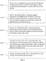
FIG. 1 is a flowchart of a method for detecting quality of service (QoS) of a BGP anycast cluster according to a first method embodiment of the present disclosure. The method in the present embodiment of the present disclosure is implemented to a detection device for detecting the QoS of the BGP anycast cluster. A quantity of detection devices may be multiple, and the detection devices are distributed in the BGP anycast cluster network. As shown inFIG. 1 , the method according to embodiments of the present disclosure may include the following content. - S101: The detection device receives detection-task information for detecting the QoS of the BGP anycast cluster, where the detection-task information includes a BGP anycast IP address.
- Specifically, the detection task may be set according to different requirements of the QoS of the BGP anycast cluster in different application scenarios. The detection-task information may be a task instruction sent by a detection-task management personnel to the detection device through other network devices, or may be a task instruction input by the detection-task management personnel through a human-computer interaction interface of the detection device. The detection device may be a surveillance device.
- S102: The detection device sends detection-request information to the BGP anycast IP address, where the detection-request information is received by an entity server in the BGP anycast cluster that has a shortest AS path from the detection device.
- For example, when detecting the QoS of a BGP anycast cluster that has an IP address 1.1.1.1, the http protocol detection-request information: GET http://www.wangsu.com/ is used, where www.wangsu.com is a test domain name to detection. The IP address comes out after analysis is 1.1.1.1, which is the BGP anycast IP address. After sending a detection-request information to the BGP anycast IP address, the detection device selects the entity server with the shortest AS path from the detection device to receive.
- S103: The detection device receives a detection-response information sent by the entity server in the BGP anycast cluster, where the detection-response information includes an IP address of the entity server.
- The detection device sends a detection-request information to the BGP anycast IP address. After receiving the detection-request information, the entity server that provides the service writes the actual IP address thereof into the response content.
- S104: The detection device generates detection index data according to the sent detection-request information and the received detection-response information, where the detection index data includes the BGP anycast IP address and the IP address of the entity server.
- After receiving the detection-response information, the detection device can accurately obtain the IP address of the detected entity server, and thus can accurately correlate the detected index data with the entity server IP and anycast IP. The detected index data may also include a status code and a response time of the entity server.
- According to the technical solutions provided by embodiments of the present disclosure, each entity server in the BGP anycast cluster can be detected by arranging multiple detection devices in the BGP anycast cluster network. After receiving the detection task of the QoS of the BGP anycast cluster, the detection device sends a detection-request information to the BGP anycast IP address to execute the detection task, where the detection-request information is received by an entity server in the BGP anycast cluster that has a shortest AS path from the detection device. Then, the entity server in the BGP anycast cluster sends the detection-response information to the detection device, where the detection-response information includes an IP address of the entity server. Thus, the detection device can generate the detection index data according to the sent detection-request information and the received detection-response information, where the detection index data includes the BGP anycast IP address and the IP address of the entity server. If the entity server fails, the failed server can be quickly found through the entity server IP. Therefore, the technical solutions provided by embodiments of the present disclosure can accurately collect the detection index data of the entity server in the BGP anycast cluster, thereby improving the QoS of the BGP anycast cluster.
-
FIG. 2 is a flowchart of a method for detecting QoS of a BGP anycast cluster according to a second method embodiment of the present disclosure. As shown inFIG. 2 , on the basis of the first method embodiment of the present disclosure shown inFIG. 1 , after the detection device generates detection index data according to the sent detection-request information and the received detection-response information in S104, the method in present embodiment may further include the following content. - S201: The detection index data is analyzed to obtain the QoS data of the entity server in the BGP anycast cluster.
- For example, based on the collected BGP anycast IP address, the IP address of the entity server, and the status code and the response time of the entity server, the service status of the entity server in the entire BGP anycast cluster can be obtained by big data analytics.
-
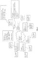
FIG. 3 is a flowchart of a method for detecting QoS of a BGP anycast cluster according to a third method embodiment of the present disclosure. As shown inFIG. 3 , in the method of the present embodiment, the detection device is a surveillance device, and the detection-request information is an http protocol detection-request information. - Assuming that the IP of the
surveillance device 1 is 1.2.3.4, and the http detection protocol is used to detection the QoS of the BGP anycast cluster with the IP address of 1.1.1.1, an initiated detection-request information is: GET http://www.wangsu.com/ (www.wangsu.com is the test domain name for detecting, and the resolved IP is 1.1.1.1). When initiating a request to an anycast IP 1.1.1.1, thesurveillance device 1 selects a node with the shortest AS path from thesurveillance device 1, which is assumed to be the server in Moscow (of which the entity server IP is 3.3.3.3), inprocess ① inFIG. 3 . After accessed by the surveillance device to the detection URL, the entity server with the IP address 3.3.3.3 writes its own physical IP 3.3.3.3 to the response content, and responds to the surveillance device 1 (IP: 1.2.3.4), inprocess ② inFIG. 3 . - When receiving the response from the server (IP 3.3.3.3) in Moscow, the
surveillance device 1 extracts the response content, and combines the BGP anycast IP, the physical machine IP, the status code, and the response time into a piece of detection data. As such, detecting for an http of a surveillance point to BGP anycast IP can be completed. By analogy, the http detection for the BGP anycast IP can be detected by a large number of surveillance devices to obtain the detection index data of the BGP anycast IP and the corresponding physical IP. Through big data analytics, the service status of the entire BGP anycast service cluster can be obtained. - In the present embodiment, when the surveillance device initiates the http request detection to the BGP anycast IP, after receiving the http request, the entity server writes the entity server IP into the response content, and after receiving the response content, the surveillance device corelates detection index (status code, the response time, etc.) with the entity server IP and BGP anycast IP to complete the collection of the detection index data.
-
FIG. 4 is a flowchart of a method for detecting QoS of a BGP Anycast cluster according to a fourth method embodiment of the present disclosure. As shown inFIG. 4 , in the method of the present embodiment, the detection-request information is DNS protocol detection-request information. Compared with the third method embodiment, the service status of the entire BGP anycast service cluster is obtained by replacing the detection protocol with the DNS protocol. The implementation principle is discussed in the third method embodiment, and thus details are not described herein again. - In the present embodiment, when the surveillance device initiates a DNS detection-request to the BGP anycast IP, after receiving the DNS request, the entity server writes the entity server IP into the response content, and after receiving the response content, the surveillance device corelates the detection index (status code, and the response time, etc.) with the entity server IP and BGP anycast IP to complete the collection of the detection index data.
- The detection devices according to embodiments of the present disclosure usually can be multiple and distributed in a BGP anycast cluster network.
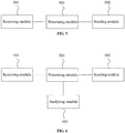
FIG. 5 is a structural diagram of a detection device according to a first device embodiment of the present disclosure. As shown inFIG. 5 , the detection device in the present embodiment may include areceiving module 501, a sendingmodule 502, and aprocessing module 503. The receivingmodule 501 is configured to receive detection-task information for detecting the QoS of the BGP Anycast cluster, where the detection-task information includes a BGP anycast IP address. The sendingmodule 502 is configured to a detection-request information to the BGP anycast IP address, where the detection-request information is received by an entity server in the BGP anycast cluster that has a shortest AS path from the detection device. The receivingdevice 501 is further configured to receive a detection-response information sent by the entity server in the BGP anycast cluster, where the detection-response information includes an IP address of the entity server. Theprocessing module 503 is configured to generate detection index data according to the sent detection-request information and the received detection-response information, where the detection index data includes the BGP anycast IP address and the IP address of the entity server. - The device in the present embodiment may be applied to perform the method according to the method embodiment shown in
FIG. 1 , and the implementation principle and the technical effect to be achieved are similar, and thus details are not described herein again. - For the device as described above, the detection-request information may be an http protocol detection-request information; the detection-request information may also be DNS protocol detection-request information; and the detection index data may further include a status code and a response time of the entity server.
- The implementation principle of the device in the present embodiment and the technical effects to be achieved are discussed above, and thus are not described herein again.
-
FIG. 6 is a structural diagram of a detection device according to a second device embodiment of the present disclosure. As shown inFIG. 6 , the detection device of the present embodiment may further include ananalyzing module 601, where theanalyzing module 601 is configured to analyze the detection index data to obtain the QoS data of the entity server in the BGP anycast cluster. -
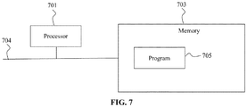
FIG. 7 is a structural diagram of a detection device according to another device embodiment of the present disclosure. As shown inFIG. 7 , the detection device includes at least one processor 701 (for example, a central processing unit (CPU)), amemory 703, and at least onecommunication bus 704 for implementing communication connection between devices. Theprocessor 701 is configured to execute an executable module, such as a computer program, stored in thememory 703. Thememory 703 may include a high-speed random-access memory (RAM), and may also include a non-volatile memory such as at least one disk memory. - In some embodiments, the
memory 703 stores aprogram 705 that can be executed by theprocessor 701. Theprogram 705 includes executing a detection method for detecting the QoS of the BGP Anycast cluster, the method includes that: - the detection device receives detection-task information for detecting the QoS of the BGP Anycast cluster, where the detection-task information includes a BGP Anycast IP address;
- the detection device sends a detection-request information to the BGP Anycast IP address, where the detection-request information is received by an entity server in the BGP Anycast cluster that has a shortest AS path from the detection device;
- the detection device receives a detection-response information sent by the entity server in the BGP Anycast cluster, where the detection-response information includes an IP address of the entity server; and
- the detection device generates detection index data according to the sent detection-request information and the received detection-response information, where the detection index data includes the BGP Anycast IP address and the IP address of the entity server.
- The above-mentioned program for performing the detection method for detecting the QoS of the BGP anycast cluster, preferably, the detection-request information is http protocol detection-request information.
- The above-mentioned program for performing the detection method for detecting the QoS of the BGP anycast cluster, preferably, the detection-request information is DNS protocol detection-request information.
- The above-mentioned program for performing the detection method for detecting the QoS of the BGP anycast cluster, preferably, the detection index data further includes a status code and a response time of the entity server.
- The above-mentioned program for performing the detection method for detecting the QoS of the BGP anycast cluster, preferably, after the detection device generates the detection index data according to the sent detection-request information and the received detection-response information, the method further includes that:
the detection index data is analyzed to obtain the QoS data of the entity server in the BGP anycast cluster. - It should be noted that the above embodiments are only used to illustrate the technical solutions of the present disclosure, and are not limited thereto; although the present disclosure has been described in detail with reference to the foregoing embodiments, those skilled in the art should understand that they can still make modifications for the technical solutions described in the foregoing embodiments, or equivalent replacements for some of the technical features. The essence of the technical solutions corresponding to those modifications and replacements is not deviated from the spirit and scope of the technical solutions of the embodiments of the present disclosure.
Claims (10)
- A method for detecting quality of service (QoS) of a border gateway protocol (BGP) anycast cluster, implemented by a detection device the method comprising:receiving, by the detection device, detection-task information for the QoS of the BGP anycast cluster, wherein the detection-task information includes a BGP anycast IP address;sending, by the detection device, detection-request information to the BGP anycast IP address, wherein the detection-request information is received by an entity server in the BGP anycast cluster that has a shortest autonomous system (AS) path from the detection device;receiving, by the detection device, detection-response information sent by the entity server in the BGP anycast cluster, wherein the detection-response information includes an IP address of the entity server; andgenerating, by the detection device, detection index data according to the sent detection-request information and the detection-response information, wherein the detection index data includes the BGP anycast IP address and the IP address of the entity server.
- The method of claim 1, wherein the detection request information includes http protocol detection-request information.
- The method of claim 1, wherein the detection-request information includes DNS protocol detection-request information.
- The method of claim 1, wherein the detection index data further includes a status code and a response time of the entity server.
- The method of any one of claims 1-4, wherein after the detection device generates the detection index data according to the sent detection-request information and the detection-response information, the method further includes:
analyzing the detection index data to obtain QoS data of the entity server in the BGP anycast cluster. - A detection device for detecting QoS of a border gateway protocol (BGP) anycast cluster, wherein:a quantity of the detection device is multiple, and the detection devices are distributed in a BGP anycast cluster network, and the detection device includes:a receiving module, configured to receive detection-task information for detecting the QoS of the BGP Anycast cluster, wherein the detection-task information includes a BGP anycast IP address; anda sending module, configured to send detection-request information to the BGP anycast IP address, wherein the detection-request information is received by an entity server in the BGP anycast cluster that has a shortest AS path from the detection device;the receiving module is further configured to receive a detection-response information sent by the entity server in the BGP anycast cluster, wherein the detection-response information includes an IP address of the entity server; andthe detection device further includes a processing module, and the processing module is configured to generate detection index data according to the sent detection-request information and the detection-response information, wherein the detection index data includes the BGP anycast IP address and the IP address of the entity server.
- The device of claim 6, wherein the detection request information includes http protocol detection request information.
- The device of claim 6, wherein the detection-request information includes DNS protocol detection-request information.
- The device of claim 6, wherein the detection index data further includes a status code and a response time of the entity server.
- The device of any one of claims 6-9, further comprising an analysis module, wherein the analyzing module is configured to analyze the detection index data to obtain QoS data of the entity server in the BGP Anycast cluster.
Applications Claiming Priority (2)
| Application Number | Priority Date | Filing Date | Title |
|---|---|---|---|
| CN201810403078.6A CN108600051B (en) | 2018-04-28 | 2018-04-28 | BGP Anycast cluster service quality detection method and detection equipment |
| PCT/CN2018/091210 WO2019205247A1 (en) | 2018-04-28 | 2018-06-14 | Bgp anycast cluster service quality detection method and detection apparatus |
Publications (3)
| Publication Number | Publication Date |
|---|---|
| EP3609134A1 true EP3609134A1 (en) | 2020-02-12 |
| EP3609134A4 EP3609134A4 (en) | 2020-05-20 |
| EP3609134B1 EP3609134B1 (en) | 2022-04-13 |
Family
ID=63620067
Family Applications (1)
| Application Number | Title | Priority Date | Filing Date |
|---|---|---|---|
| EP18915781.1A Active EP3609134B1 (en) | 2018-04-28 | 2018-06-14 | Bgp anycast cluster service quality detection method and detection apparatus |
Country Status (4)
| Country | Link |
|---|---|
| US (1) | US20210336861A1 (en) |
| EP (1) | EP3609134B1 (en) |
| CN (1) | CN108600051B (en) |
| WO (1) | WO2019205247A1 (en) |
Cited By (1)
| Publication number | Priority date | Publication date | Assignee | Title |
|---|---|---|---|---|
| WO2022272206A1 (en) * | 2021-06-22 | 2022-12-29 | Level 3 Communications, Llc | Network optimization system using latency measurements |
Families Citing this family (4)
| Publication number | Priority date | Publication date | Assignee | Title |
|---|---|---|---|---|
| CN110933128B (en) * | 2019-10-08 | 2021-04-16 | 网宿科技股份有限公司 | Node traffic scheduling method and device, electronic equipment and storage medium |
| CN112615781B (en) * | 2020-12-09 | 2023-04-18 | 网宿科技股份有限公司 | Method and server for realizing BGP message interaction in DPDK |
| CN113872824B (en) * | 2021-08-19 | 2023-04-07 | 网宿科技股份有限公司 | CDN network quality detection method, system, server and storage medium |
| CN114500252A (en) * | 2021-12-20 | 2022-05-13 | 奇安信科技集团股份有限公司 | DNS service condition monitoring method and device, electronic equipment and storage medium |
Family Cites Families (9)
| Publication number | Priority date | Publication date | Assignee | Title |
|---|---|---|---|---|
| JP3484352B2 (en) * | 1998-08-26 | 2004-01-06 | 日本電信電話株式会社 | Address conversion method and apparatus for call processing |
| US7058706B1 (en) * | 2000-03-31 | 2006-06-06 | Akamai Technologies, Inc. | Method and apparatus for determining latency between multiple servers and a client |
| US20090172192A1 (en) * | 2007-12-28 | 2009-07-02 | Christian Michael F | Mapless Global Traffic Load Balancing Via Anycast |
| CN101610183B (en) * | 2009-07-21 | 2011-05-11 | 杭州华三通信技术有限公司 | Method and device for probing processing ability of hypertext transfer protocol server |
| CN103354525A (en) * | 2013-06-08 | 2013-10-16 | 中国科学院计算机网络信息中心 | System and method for realizing wide area network anycast load balancing based on OpenFlow |
| CN104469695B (en) * | 2013-09-12 | 2019-02-05 | 华为技术有限公司 | Method for network access, short-range communication server, link terminal and terminal |
| CN107465564B (en) * | 2016-06-03 | 2020-05-19 | 德科仕通信(上海)有限公司 | VOD service quality monitoring system and method |
| CN107465526B (en) * | 2016-06-03 | 2020-05-15 | 德科仕通信(上海)有限公司 | Internet video CDN server quality monitoring system and method |
| CN107528862B (en) * | 2017-10-23 | 2021-04-30 | 京东数字科技控股有限公司 | Domain name resolution method and device |
-
2018
- 2018-04-28 CN CN201810403078.6A patent/CN108600051B/en not_active Expired - Fee Related
- 2018-06-14 WO PCT/CN2018/091210 patent/WO2019205247A1/en unknown
- 2018-06-14 EP EP18915781.1A patent/EP3609134B1/en active Active
- 2018-06-14 US US16/481,698 patent/US20210336861A1/en not_active Abandoned
Cited By (2)
| Publication number | Priority date | Publication date | Assignee | Title |
|---|---|---|---|---|
| WO2022272206A1 (en) * | 2021-06-22 | 2022-12-29 | Level 3 Communications, Llc | Network optimization system using latency measurements |
| US11689611B2 (en) | 2021-06-22 | 2023-06-27 | Level 3 Communications, Llc | Network optimization system using server latency measurements |
Also Published As
| Publication number | Publication date |
|---|---|
| CN108600051A (en) | 2018-09-28 |
| EP3609134A4 (en) | 2020-05-20 |
| CN108600051B (en) | 2020-02-18 |
| WO2019205247A1 (en) | 2019-10-31 |
| US20210336861A1 (en) | 2021-10-28 |
| EP3609134B1 (en) | 2022-04-13 |
Similar Documents
| Publication | Publication Date | Title |
|---|---|---|
| EP3609134B1 (en) | Bgp anycast cluster service quality detection method and detection apparatus | |
| US11316786B2 (en) | Systems and methods for directly responding to distributed network traffic | |
| US10505977B2 (en) | Diffusing denial-of-service attacks by using virtual machines | |
| US10320644B1 (en) | Traffic analyzer for isolated virtual networks | |
| CN110247784B (en) | Method and device for determining network topology structure | |
| CN112702214B (en) | Method and system for configuring a network | |
| US20200272920A1 (en) | Artificial intelligence delivery edge network | |
| US10951489B2 (en) | SLA compliance determination with real user monitoring | |
| CN107613037B (en) | Domain name redirection method and system | |
| CN107635010B (en) | Traffic scheduling method and device, computer readable storage medium and electronic equipment | |
| CN108183975A (en) | A kind of method and system of domain name mapping | |
| IL268670A (en) | Automatic server cluster discovery | |
| CN114520784B (en) | Dynamic content acceleration access method and device | |
| US11630756B2 (en) | Methods and systems for measuring user and system metrics | |
| CN112242937B (en) | Network speed measuring method and device, electronic equipment and computer readable medium | |
| US20220141279A1 (en) | Client-side measurement of computer network conditions | |
| US10484276B2 (en) | Route resolution system and route resolution method | |
| Mandalari et al. | Informing protocol design through crowdsourcing: the case of pervasive encryption | |
| Sun | Latency-aware optimization of the existing service mesh in edge computing environment | |
| JP5404855B2 (en) | CDN introduction status determination apparatus, CDN introduction status determination method, and program | |
| Dasari et al. | Application Performance Monitoring in Software Defined Networks | |
| US20230112101A1 (en) | Cross-plane monitoring intent and policy instantiation for network analytics and assurance | |
| CN117395227A (en) | Service processing method, device, electronic equipment and storage medium | |
| Petroski et al. | ANALISYS OF A EVENT ORIENTED WEB SERVER AS A REVERSE PROXY WITH FLEXIBLE LOAD DISTRIBUTION | |
| Pfitscher | Monitoring and identifying bottlenecks in virtual network functions service chains |
Legal Events
| Date | Code | Title | Description |
|---|---|---|---|
| STAA | Information on the status of an ep patent application or granted ep patent |
Free format text: STATUS: UNKNOWN |
|
| STAA | Information on the status of an ep patent application or granted ep patent |
Free format text: STATUS: THE INTERNATIONAL PUBLICATION HAS BEEN MADE |
|
| PUAI | Public reference made under article 153(3) epc to a published international application that has entered the european phase |
Free format text: ORIGINAL CODE: 0009012 |
|
| STAA | Information on the status of an ep patent application or granted ep patent |
Free format text: STATUS: REQUEST FOR EXAMINATION WAS MADE |
|
| 17P | Request for examination filed |
Effective date: 20191029 |
|
| AK | Designated contracting states |
Kind code of ref document: A1 Designated state(s): AL AT BE BG CH CY CZ DE DK EE ES FI FR GB GR HR HU IE IS IT LI LT LU LV MC MK MT NL NO PL PT RO RS SE SI SK SM TR |
|
| AX | Request for extension of the european patent |
Extension state: BA ME |
|
| A4 | Supplementary search report drawn up and despatched |
Effective date: 20200420 |
|
| RIC1 | Information provided on ipc code assigned before grant |
Ipc: H04L 12/28 20060101AFI20200414BHEP Ipc: H04L 12/721 20130101ALI20200414BHEP Ipc: H04L 12/26 20060101ALI20200414BHEP Ipc: H04L 12/24 20060101ALI20200414BHEP |
|
| DAV | Request for validation of the european patent (deleted) | ||
| DAX | Request for extension of the european patent (deleted) | ||
| GRAP | Despatch of communication of intention to grant a patent |
Free format text: ORIGINAL CODE: EPIDOSNIGR1 |
|
| STAA | Information on the status of an ep patent application or granted ep patent |
Free format text: STATUS: GRANT OF PATENT IS INTENDED |
|
| INTG | Intention to grant announced |
Effective date: 20220104 |
|
| GRAS | Grant fee paid |
Free format text: ORIGINAL CODE: EPIDOSNIGR3 |
|
| GRAA | (expected) grant |
Free format text: ORIGINAL CODE: 0009210 |
|
| STAA | Information on the status of an ep patent application or granted ep patent |
Free format text: STATUS: THE PATENT HAS BEEN GRANTED |
|
| AK | Designated contracting states |
Kind code of ref document: B1 Designated state(s): AL AT BE BG CH CY CZ DE DK EE ES FI FR GB GR HR HU IE IS IT LI LT LU LV MC MK MT NL NO PL PT RO RS SE SI SK SM TR |
|
| REG | Reference to a national code |
Ref country code: GB Ref legal event code: FG4D |
|
| REG | Reference to a national code |
Ref country code: CH Ref legal event code: EP |
|
| REG | Reference to a national code |
Ref country code: DE Ref legal event code: R096 Ref document number: 602018033980 Country of ref document: DE |
|
| REG | Reference to a national code |
Ref country code: IE Ref legal event code: FG4D |
|
| REG | Reference to a national code |
Ref country code: AT Ref legal event code: REF Ref document number: 1484254 Country of ref document: AT Kind code of ref document: T Effective date: 20220515 |
|
| PGFP | Annual fee paid to national office [announced via postgrant information from national office to epo] |
Ref country code: DE Payment date: 20220607 Year of fee payment: 5 |
|
| REG | Reference to a national code |
Ref country code: LT Ref legal event code: MG9D |
|
| REG | Reference to a national code |
Ref country code: NL Ref legal event code: MP Effective date: 20220413 |
|
| REG | Reference to a national code |
Ref country code: AT Ref legal event code: MK05 Ref document number: 1484254 Country of ref document: AT Kind code of ref document: T Effective date: 20220413 |
|
| PG25 | Lapsed in a contracting state [announced via postgrant information from national office to epo] |
Ref country code: NL Free format text: LAPSE BECAUSE OF FAILURE TO SUBMIT A TRANSLATION OF THE DESCRIPTION OR TO PAY THE FEE WITHIN THE PRESCRIBED TIME-LIMIT Effective date: 20220413 |
|
| PG25 | Lapsed in a contracting state [announced via postgrant information from national office to epo] |
Ref country code: SE Free format text: LAPSE BECAUSE OF FAILURE TO SUBMIT A TRANSLATION OF THE DESCRIPTION OR TO PAY THE FEE WITHIN THE PRESCRIBED TIME-LIMIT Effective date: 20220413 Ref country code: PT Free format text: LAPSE BECAUSE OF FAILURE TO SUBMIT A TRANSLATION OF THE DESCRIPTION OR TO PAY THE FEE WITHIN THE PRESCRIBED TIME-LIMIT Effective date: 20220816 Ref country code: NO Free format text: LAPSE BECAUSE OF FAILURE TO SUBMIT A TRANSLATION OF THE DESCRIPTION OR TO PAY THE FEE WITHIN THE PRESCRIBED TIME-LIMIT Effective date: 20220713 Ref country code: LT Free format text: LAPSE BECAUSE OF FAILURE TO SUBMIT A TRANSLATION OF THE DESCRIPTION OR TO PAY THE FEE WITHIN THE PRESCRIBED TIME-LIMIT Effective date: 20220413 Ref country code: HR Free format text: LAPSE BECAUSE OF FAILURE TO SUBMIT A TRANSLATION OF THE DESCRIPTION OR TO PAY THE FEE WITHIN THE PRESCRIBED TIME-LIMIT Effective date: 20220413 Ref country code: GR Free format text: LAPSE BECAUSE OF FAILURE TO SUBMIT A TRANSLATION OF THE DESCRIPTION OR TO PAY THE FEE WITHIN THE PRESCRIBED TIME-LIMIT Effective date: 20220714 Ref country code: FI Free format text: LAPSE BECAUSE OF FAILURE TO SUBMIT A TRANSLATION OF THE DESCRIPTION OR TO PAY THE FEE WITHIN THE PRESCRIBED TIME-LIMIT Effective date: 20220413 Ref country code: ES Free format text: LAPSE BECAUSE OF FAILURE TO SUBMIT A TRANSLATION OF THE DESCRIPTION OR TO PAY THE FEE WITHIN THE PRESCRIBED TIME-LIMIT Effective date: 20220413 Ref country code: BG Free format text: LAPSE BECAUSE OF FAILURE TO SUBMIT A TRANSLATION OF THE DESCRIPTION OR TO PAY THE FEE WITHIN THE PRESCRIBED TIME-LIMIT Effective date: 20220713 Ref country code: AT Free format text: LAPSE BECAUSE OF FAILURE TO SUBMIT A TRANSLATION OF THE DESCRIPTION OR TO PAY THE FEE WITHIN THE PRESCRIBED TIME-LIMIT Effective date: 20220413 |
|
| PG25 | Lapsed in a contracting state [announced via postgrant information from national office to epo] |
Ref country code: RS Free format text: LAPSE BECAUSE OF FAILURE TO SUBMIT A TRANSLATION OF THE DESCRIPTION OR TO PAY THE FEE WITHIN THE PRESCRIBED TIME-LIMIT Effective date: 20220413 Ref country code: PL Free format text: LAPSE BECAUSE OF FAILURE TO SUBMIT A TRANSLATION OF THE DESCRIPTION OR TO PAY THE FEE WITHIN THE PRESCRIBED TIME-LIMIT Effective date: 20220413 Ref country code: LV Free format text: LAPSE BECAUSE OF FAILURE TO SUBMIT A TRANSLATION OF THE DESCRIPTION OR TO PAY THE FEE WITHIN THE PRESCRIBED TIME-LIMIT Effective date: 20220413 Ref country code: IS Free format text: LAPSE BECAUSE OF FAILURE TO SUBMIT A TRANSLATION OF THE DESCRIPTION OR TO PAY THE FEE WITHIN THE PRESCRIBED TIME-LIMIT Effective date: 20220813 |
|
| REG | Reference to a national code |
Ref country code: DE Ref legal event code: R097 Ref document number: 602018033980 Country of ref document: DE |
|
| PG25 | Lapsed in a contracting state [announced via postgrant information from national office to epo] |
Ref country code: SM Free format text: LAPSE BECAUSE OF FAILURE TO SUBMIT A TRANSLATION OF THE DESCRIPTION OR TO PAY THE FEE WITHIN THE PRESCRIBED TIME-LIMIT Effective date: 20220413 Ref country code: SK Free format text: LAPSE BECAUSE OF FAILURE TO SUBMIT A TRANSLATION OF THE DESCRIPTION OR TO PAY THE FEE WITHIN THE PRESCRIBED TIME-LIMIT Effective date: 20220413 Ref country code: RO Free format text: LAPSE BECAUSE OF FAILURE TO SUBMIT A TRANSLATION OF THE DESCRIPTION OR TO PAY THE FEE WITHIN THE PRESCRIBED TIME-LIMIT Effective date: 20220413 Ref country code: MC Free format text: LAPSE BECAUSE OF FAILURE TO SUBMIT A TRANSLATION OF THE DESCRIPTION OR TO PAY THE FEE WITHIN THE PRESCRIBED TIME-LIMIT Effective date: 20220413 Ref country code: EE Free format text: LAPSE BECAUSE OF FAILURE TO SUBMIT A TRANSLATION OF THE DESCRIPTION OR TO PAY THE FEE WITHIN THE PRESCRIBED TIME-LIMIT Effective date: 20220413 Ref country code: DK Free format text: LAPSE BECAUSE OF FAILURE TO SUBMIT A TRANSLATION OF THE DESCRIPTION OR TO PAY THE FEE WITHIN THE PRESCRIBED TIME-LIMIT Effective date: 20220413 Ref country code: CZ Free format text: LAPSE BECAUSE OF FAILURE TO SUBMIT A TRANSLATION OF THE DESCRIPTION OR TO PAY THE FEE WITHIN THE PRESCRIBED TIME-LIMIT Effective date: 20220413 |
|
| REG | Reference to a national code |
Ref country code: CH Ref legal event code: PL |
|
| PLBE | No opposition filed within time limit |
Free format text: ORIGINAL CODE: 0009261 |
|
| STAA | Information on the status of an ep patent application or granted ep patent |
Free format text: STATUS: NO OPPOSITION FILED WITHIN TIME LIMIT |
|
| REG | Reference to a national code |
Ref country code: BE Ref legal event code: MM Effective date: 20220630 |
|
| 26N | No opposition filed |
Effective date: 20230116 |
|
| GBPC | Gb: european patent ceased through non-payment of renewal fee |
Effective date: 20220713 |
|
| PG25 | Lapsed in a contracting state [announced via postgrant information from national office to epo] |
Ref country code: AL Free format text: LAPSE BECAUSE OF FAILURE TO SUBMIT A TRANSLATION OF THE DESCRIPTION OR TO PAY THE FEE WITHIN THE PRESCRIBED TIME-LIMIT Effective date: 20220413 |
|
| PG25 | Lapsed in a contracting state [announced via postgrant information from national office to epo] |
Ref country code: LU Free format text: LAPSE BECAUSE OF NON-PAYMENT OF DUE FEES Effective date: 20220614 Ref country code: LI Free format text: LAPSE BECAUSE OF NON-PAYMENT OF DUE FEES Effective date: 20220630 Ref country code: IE Free format text: LAPSE BECAUSE OF NON-PAYMENT OF DUE FEES Effective date: 20220614 Ref country code: FR Free format text: LAPSE BECAUSE OF NON-PAYMENT OF DUE FEES Effective date: 20220630 Ref country code: CH Free format text: LAPSE BECAUSE OF NON-PAYMENT OF DUE FEES Effective date: 20220630 |
|
| PG25 | Lapsed in a contracting state [announced via postgrant information from national office to epo] |
Ref country code: SI Free format text: LAPSE BECAUSE OF FAILURE TO SUBMIT A TRANSLATION OF THE DESCRIPTION OR TO PAY THE FEE WITHIN THE PRESCRIBED TIME-LIMIT Effective date: 20220413 Ref country code: GB Free format text: LAPSE BECAUSE OF NON-PAYMENT OF DUE FEES Effective date: 20220713 Ref country code: BE Free format text: LAPSE BECAUSE OF NON-PAYMENT OF DUE FEES Effective date: 20220630 |
|
| REG | Reference to a national code |
Ref country code: DE Ref legal event code: R119 Ref document number: 602018033980 Country of ref document: DE |
|
| PG25 | Lapsed in a contracting state [announced via postgrant information from national office to epo] |
Ref country code: IT Free format text: LAPSE BECAUSE OF FAILURE TO SUBMIT A TRANSLATION OF THE DESCRIPTION OR TO PAY THE FEE WITHIN THE PRESCRIBED TIME-LIMIT Effective date: 20220413 |