EP3609028A1 - Laseranordnung, spektrometer und verfahren zum betrieb eines lasers - Google Patents
Laseranordnung, spektrometer und verfahren zum betrieb eines lasers Download PDFInfo
- Publication number
- EP3609028A1 EP3609028A1 EP18188432.1A EP18188432A EP3609028A1 EP 3609028 A1 EP3609028 A1 EP 3609028A1 EP 18188432 A EP18188432 A EP 18188432A EP 3609028 A1 EP3609028 A1 EP 3609028A1
- Authority
- EP
- European Patent Office
- Prior art keywords
- laser
- electric contact
- standing wave
- wave cavity
- electrical
- Prior art date
- Legal status (The legal status is an assumption and is not a legal conclusion. Google has not performed a legal analysis and makes no representation as to the accuracy of the status listed.)
- Withdrawn
Links
- 238000000034 method Methods 0.000 title claims description 48
- 238000002347 injection Methods 0.000 claims abstract description 106
- 239000007924 injection Substances 0.000 claims abstract description 106
- 238000005086 pumping Methods 0.000 claims abstract description 7
- 230000003287 optical effect Effects 0.000 claims description 86
- 238000010009 beating Methods 0.000 claims description 58
- 239000012491 analyte Substances 0.000 claims description 33
- 238000004611 spectroscopical analysis Methods 0.000 claims description 28
- 230000008878 coupling Effects 0.000 claims description 20
- 238000010168 coupling process Methods 0.000 claims description 20
- 238000005859 coupling reaction Methods 0.000 claims description 20
- 230000001419 dependent effect Effects 0.000 claims description 17
- 239000003990 capacitor Substances 0.000 claims description 2
- 238000001228 spectrum Methods 0.000 description 45
- 210000001520 comb Anatomy 0.000 description 37
- 230000003993 interaction Effects 0.000 description 18
- 230000010349 pulsation Effects 0.000 description 18
- 230000000712 assembly Effects 0.000 description 13
- 238000000429 assembly Methods 0.000 description 13
- 239000004065 semiconductor Substances 0.000 description 13
- 238000005033 Fourier transform infrared spectroscopy Methods 0.000 description 12
- 230000001427 coherent effect Effects 0.000 description 12
- 230000006641 stabilisation Effects 0.000 description 11
- 238000011105 stabilization Methods 0.000 description 11
- 230000000694 effects Effects 0.000 description 10
- 239000006185 dispersion Substances 0.000 description 9
- 230000003111 delayed effect Effects 0.000 description 8
- 238000002161 passivation Methods 0.000 description 8
- 230000003595 spectral effect Effects 0.000 description 8
- 230000001360 synchronised effect Effects 0.000 description 8
- 230000006870 function Effects 0.000 description 7
- 238000005259 measurement Methods 0.000 description 7
- 230000007246 mechanism Effects 0.000 description 7
- 238000002156 mixing Methods 0.000 description 7
- 239000000758 substrate Substances 0.000 description 7
- 230000008901 benefit Effects 0.000 description 6
- 238000002474 experimental method Methods 0.000 description 6
- 230000010363 phase shift Effects 0.000 description 6
- 230000007704 transition Effects 0.000 description 6
- 230000015572 biosynthetic process Effects 0.000 description 5
- 230000009977 dual effect Effects 0.000 description 5
- 230000003071 parasitic effect Effects 0.000 description 5
- 238000012512 characterization method Methods 0.000 description 4
- 230000010355 oscillation Effects 0.000 description 4
- 230000008569 process Effects 0.000 description 4
- 239000013074 reference sample Substances 0.000 description 4
- RYGMFSIKBFXOCR-UHFFFAOYSA-N Copper Chemical compound [Cu] RYGMFSIKBFXOCR-UHFFFAOYSA-N 0.000 description 3
- 239000000969 carrier Substances 0.000 description 3
- 229910052802 copper Inorganic materials 0.000 description 3
- 239000010949 copper Substances 0.000 description 3
- 230000001186 cumulative effect Effects 0.000 description 3
- 230000001934 delay Effects 0.000 description 3
- 238000010586 diagram Methods 0.000 description 3
- 230000007613 environmental effect Effects 0.000 description 3
- 238000009615 fourier-transform spectroscopy Methods 0.000 description 3
- 239000012212 insulator Substances 0.000 description 3
- 238000004519 manufacturing process Methods 0.000 description 3
- 230000004044 response Effects 0.000 description 3
- 238000010408 sweeping Methods 0.000 description 3
- 230000002123 temporal effect Effects 0.000 description 3
- 229910052581 Si3N4 Inorganic materials 0.000 description 2
- 238000010521 absorption reaction Methods 0.000 description 2
- 230000007423 decrease Effects 0.000 description 2
- 238000006073 displacement reaction Methods 0.000 description 2
- 238000000295 emission spectrum Methods 0.000 description 2
- 238000005516 engineering process Methods 0.000 description 2
- 230000000670 limiting effect Effects 0.000 description 2
- 238000002044 microwave spectrum Methods 0.000 description 2
- 239000013307 optical fiber Substances 0.000 description 2
- 238000011084 recovery Methods 0.000 description 2
- 239000000523 sample Substances 0.000 description 2
- HQVNEWCFYHHQES-UHFFFAOYSA-N silicon nitride Chemical compound N12[Si]34N5[Si]62N3[Si]51N64 HQVNEWCFYHHQES-UHFFFAOYSA-N 0.000 description 2
- 230000001629 suppression Effects 0.000 description 2
- 230000036962 time dependent Effects 0.000 description 2
- 229910001258 titanium gold Inorganic materials 0.000 description 2
- 241001417527 Pempheridae Species 0.000 description 1
- XUIMIQQOPSSXEZ-UHFFFAOYSA-N Silicon Chemical compound [Si] XUIMIQQOPSSXEZ-UHFFFAOYSA-N 0.000 description 1
- 239000006096 absorbing agent Substances 0.000 description 1
- 238000000862 absorption spectrum Methods 0.000 description 1
- 238000013459 approach Methods 0.000 description 1
- 238000003491 array Methods 0.000 description 1
- 230000002238 attenuated effect Effects 0.000 description 1
- 230000005540 biological transmission Effects 0.000 description 1
- 238000006243 chemical reaction Methods 0.000 description 1
- 230000001687 destabilization Effects 0.000 description 1
- 230000005684 electric field Effects 0.000 description 1
- 230000005284 excitation Effects 0.000 description 1
- 230000017525 heat dissipation Effects 0.000 description 1
- CPBQJMYROZQQJC-UHFFFAOYSA-N helium neon Chemical compound [He].[Ne] CPBQJMYROZQQJC-UHFFFAOYSA-N 0.000 description 1
- 238000003384 imaging method Methods 0.000 description 1
- 230000006872 improvement Effects 0.000 description 1
- 229910052738 indium Inorganic materials 0.000 description 1
- APFVFJFRJDLVQX-UHFFFAOYSA-N indium atom Chemical compound [In] APFVFJFRJDLVQX-UHFFFAOYSA-N 0.000 description 1
- 238000011835 investigation Methods 0.000 description 1
- 230000000737 periodic effect Effects 0.000 description 1
- 238000000206 photolithography Methods 0.000 description 1
- 238000001020 plasma etching Methods 0.000 description 1
- 230000002829 reductive effect Effects 0.000 description 1
- SBIBMFFZSBJNJF-UHFFFAOYSA-N selenium;zinc Chemical compound [Se]=[Zn] SBIBMFFZSBJNJF-UHFFFAOYSA-N 0.000 description 1
- 230000035945 sensitivity Effects 0.000 description 1
- 238000000926 separation method Methods 0.000 description 1
- 229910052710 silicon Inorganic materials 0.000 description 1
- 239000010703 silicon Substances 0.000 description 1
- 239000000243 solution Substances 0.000 description 1
- 230000003068 static effect Effects 0.000 description 1
- 239000000126 substance Substances 0.000 description 1
- 238000003786 synthesis reaction Methods 0.000 description 1
- 230000009466 transformation Effects 0.000 description 1
Images


Classifications
-
- H—ELECTRICITY
- H01—ELECTRIC ELEMENTS
- H01S—DEVICES USING THE PROCESS OF LIGHT AMPLIFICATION BY STIMULATED EMISSION OF RADIATION [LASER] TO AMPLIFY OR GENERATE LIGHT; DEVICES USING STIMULATED EMISSION OF ELECTROMAGNETIC RADIATION IN WAVE RANGES OTHER THAN OPTICAL
- H01S5/00—Semiconductor lasers
- H01S5/06—Arrangements for controlling the laser output parameters, e.g. by operating on the active medium
- H01S5/062—Arrangements for controlling the laser output parameters, e.g. by operating on the active medium by varying the potential of the electrodes
- H01S5/0625—Arrangements for controlling the laser output parameters, e.g. by operating on the active medium by varying the potential of the electrodes in multi-section lasers
- H01S5/06255—Controlling the frequency of the radiation
-
- G—PHYSICS
- G01—MEASURING; TESTING
- G01N—INVESTIGATING OR ANALYSING MATERIALS BY DETERMINING THEIR CHEMICAL OR PHYSICAL PROPERTIES
- G01N21/00—Investigating or analysing materials by the use of optical means, i.e. using sub-millimetre waves, infrared, visible or ultraviolet light
- G01N21/17—Systems in which incident light is modified in accordance with the properties of the material investigated
- G01N21/25—Colour; Spectral properties, i.e. comparison of effect of material on the light at two or more different wavelengths or wavelength bands
- G01N21/31—Investigating relative effect of material at wavelengths characteristic of specific elements or molecules, e.g. atomic absorption spectrometry
- G01N21/39—Investigating relative effect of material at wavelengths characteristic of specific elements or molecules, e.g. atomic absorption spectrometry using tunable lasers
-
- H—ELECTRICITY
- H01—ELECTRIC ELEMENTS
- H01S—DEVICES USING THE PROCESS OF LIGHT AMPLIFICATION BY STIMULATED EMISSION OF RADIATION [LASER] TO AMPLIFY OR GENERATE LIGHT; DEVICES USING STIMULATED EMISSION OF ELECTROMAGNETIC RADIATION IN WAVE RANGES OTHER THAN OPTICAL
- H01S5/00—Semiconductor lasers
- H01S5/06—Arrangements for controlling the laser output parameters, e.g. by operating on the active medium
- H01S5/065—Mode locking; Mode suppression; Mode selection ; Self pulsating
- H01S5/0657—Mode locking, i.e. generation of pulses at a frequency corresponding to a roundtrip in the cavity
-
- H—ELECTRICITY
- H01—ELECTRIC ELEMENTS
- H01S—DEVICES USING THE PROCESS OF LIGHT AMPLIFICATION BY STIMULATED EMISSION OF RADIATION [LASER] TO AMPLIFY OR GENERATE LIGHT; DEVICES USING STIMULATED EMISSION OF ELECTROMAGNETIC RADIATION IN WAVE RANGES OTHER THAN OPTICAL
- H01S5/00—Semiconductor lasers
- H01S5/30—Structure or shape of the active region; Materials used for the active region
- H01S5/34—Structure or shape of the active region; Materials used for the active region comprising quantum well or superlattice structures, e.g. single quantum well [SQW] lasers, multiple quantum well [MQW] lasers or graded index separate confinement heterostructure [GRINSCH] lasers
- H01S5/3401—Structure or shape of the active region; Materials used for the active region comprising quantum well or superlattice structures, e.g. single quantum well [SQW] lasers, multiple quantum well [MQW] lasers or graded index separate confinement heterostructure [GRINSCH] lasers having no PN junction, e.g. unipolar lasers, intersubband lasers, quantum cascade lasers
- H01S5/3402—Structure or shape of the active region; Materials used for the active region comprising quantum well or superlattice structures, e.g. single quantum well [SQW] lasers, multiple quantum well [MQW] lasers or graded index separate confinement heterostructure [GRINSCH] lasers having no PN junction, e.g. unipolar lasers, intersubband lasers, quantum cascade lasers intersubband lasers, e.g. transitions within the conduction or valence bands
-
- H—ELECTRICITY
- H01—ELECTRIC ELEMENTS
- H01S—DEVICES USING THE PROCESS OF LIGHT AMPLIFICATION BY STIMULATED EMISSION OF RADIATION [LASER] TO AMPLIFY OR GENERATE LIGHT; DEVICES USING STIMULATED EMISSION OF ELECTROMAGNETIC RADIATION IN WAVE RANGES OTHER THAN OPTICAL
- H01S5/00—Semiconductor lasers
- H01S5/005—Optical components external to the laser cavity, specially adapted therefor, e.g. for homogenisation or merging of the beams or for manipulating laser pulses, e.g. pulse shaping
- H01S5/0071—Optical components external to the laser cavity, specially adapted therefor, e.g. for homogenisation or merging of the beams or for manipulating laser pulses, e.g. pulse shaping for beam steering, e.g. using a mirror outside the cavity to change the beam direction
-
- H—ELECTRICITY
- H01—ELECTRIC ELEMENTS
- H01S—DEVICES USING THE PROCESS OF LIGHT AMPLIFICATION BY STIMULATED EMISSION OF RADIATION [LASER] TO AMPLIFY OR GENERATE LIGHT; DEVICES USING STIMULATED EMISSION OF ELECTROMAGNETIC RADIATION IN WAVE RANGES OTHER THAN OPTICAL
- H01S5/00—Semiconductor lasers
- H01S5/005—Optical components external to the laser cavity, specially adapted therefor, e.g. for homogenisation or merging of the beams or for manipulating laser pulses, e.g. pulse shaping
- H01S5/0085—Optical components external to the laser cavity, specially adapted therefor, e.g. for homogenisation or merging of the beams or for manipulating laser pulses, e.g. pulse shaping for modulating the output, i.e. the laser beam is modulated outside the laser cavity
-
- H—ELECTRICITY
- H01—ELECTRIC ELEMENTS
- H01S—DEVICES USING THE PROCESS OF LIGHT AMPLIFICATION BY STIMULATED EMISSION OF RADIATION [LASER] TO AMPLIFY OR GENERATE LIGHT; DEVICES USING STIMULATED EMISSION OF ELECTROMAGNETIC RADIATION IN WAVE RANGES OTHER THAN OPTICAL
- H01S5/00—Semiconductor lasers
- H01S5/04—Processes or apparatus for excitation, e.g. pumping, e.g. by electron beams
- H01S5/042—Electrical excitation ; Circuits therefor
- H01S5/0425—Electrodes, e.g. characterised by the structure
- H01S5/04256—Electrodes, e.g. characterised by the structure characterised by the configuration
-
- H—ELECTRICITY
- H01—ELECTRIC ELEMENTS
- H01S—DEVICES USING THE PROCESS OF LIGHT AMPLIFICATION BY STIMULATED EMISSION OF RADIATION [LASER] TO AMPLIFY OR GENERATE LIGHT; DEVICES USING STIMULATED EMISSION OF ELECTROMAGNETIC RADIATION IN WAVE RANGES OTHER THAN OPTICAL
- H01S5/00—Semiconductor lasers
- H01S5/30—Structure or shape of the active region; Materials used for the active region
- H01S5/34—Structure or shape of the active region; Materials used for the active region comprising quantum well or superlattice structures, e.g. single quantum well [SQW] lasers, multiple quantum well [MQW] lasers or graded index separate confinement heterostructure [GRINSCH] lasers
- H01S5/3401—Structure or shape of the active region; Materials used for the active region comprising quantum well or superlattice structures, e.g. single quantum well [SQW] lasers, multiple quantum well [MQW] lasers or graded index separate confinement heterostructure [GRINSCH] lasers having no PN junction, e.g. unipolar lasers, intersubband lasers, quantum cascade lasers
Definitions
- the present disclosure concerns a laser assembly comprising a laser with a fast gain medium, in particular a quantum cascade laser (QCL) or an interband cascade laser (ICL), and a standing wave cavity; a DC source coupled to the standing wave cavity for pumping the laser; an AC injection device for injecting an electrical AC signal into the standing wave cavity and optionally a grounded substrate.
- a fast gain medium in particular a quantum cascade laser (QCL) or an interband cascade laser (ICL)
- ICL interband cascade laser
- the present disclosure further concerns a spectrometer for frequency comb spectroscopy of an analyte.
- the present disclosure concerns a method of operating a laser with a fast gain medium, in particular a quantum cascade laser or an interband cascade laser, and a method of frequency comb spectroscopy.
- Optical frequency combs are lasers whose spectrum consists of a multitude of equidistant lines.
- Optical frequency combs have already been applied to a variety of technologies, such as time metrology, frequency synthesis and high-precision spectroscopy.
- MIR mid-infrared spectral region
- Dual comb spectroscopy could lead to a breakthrough in miniaturization and chemical sensing technology. Dual comb spectroscopy allows the simultaneous down-conversion of a multitude of spectral lines from the optical to the radio-frequency domain, where it can be analysed by state-of-the-art electronics.
- semiconductor laser frequency combs have been realized mostly by mode-locking, where the laser modes are synchronized in such a way that the intermodal difference phases are constant and thus, short optical pulses are generated.
- quantum cascade laser frequency combs are realized via minimization of the laser cavity dispersion.
- the dynamics and non-linear processes of this type of laser lead to a very different phase locking mechanism, which does not lead to short pulse generation and herein is referred to as FM type comb.
- the consequence of excessive dispersion is mainly that the laser does not operate in the frequency comb regime over the whole range of laser bias, but rather in a regime with drastically increased phase-noise. In order to avoid this regime, the dispersion of the laser cavity has to be minimized.
- the laser comprises a section with a slow gain medium and a section proximate to an end of a the laser cavity with a fast absorber medium.
- a multi-segment laser structure is used, because as a problem in a single segment device it is identified that it would be difficult to get short single pulse outputs from the laser and secondary pulses spaced at the round-trip time in the laser diode would often be generated.
- Time-dependent population inversion gratings in laser frequency combs in Optica, Vol. 5, No. 4, by Piccardo et al (April 2018 ) describes that the modes of a quantum cascade laser frequency comb coherently beat to produce time-dependent population inversion gratings, which spatially modulate the current in the device at frequencies equal to the mode separation and its higher harmonics. It mentions the electrical beat-note produced by the intermodal beating of adjacent cavity modes and the spatial dependence of both amplitude and phase of the beat signal across the laser cavity.
- the electrical beat-note power patterns exhibit antinodes at the edges of the cavity and a number of nodes equal to the order of the intermodal beat-note and that the corresponding phase profiles show a smooth phase transition between 0 and pi ( ⁇ ) at the positions of the power nodes, indicating that adjacent lobes of the power profile oscillate in antiphase.
- this paper does not suggest in any way how the frequency comb could be injection locked.
- a compact source of optical frequency combs providing the possibility for miniaturization and enabling the use for miniaturized optical spectrometers, that is cost-effective, has low power requirements, is suitable for MIR spectroscopy, enables stabilization of forced FM type combs, free-running FM type combs or FM type combs operating in the high phase noise regime, while maintaining the intermodal coherence and/or phase profile, in particular to make them more robust against various type of noise, fluctuations and drifts, as well as optical feedback, enabling much simpler optical setups without the need of optical insulators, is all-electrical, and/or enables dual-comb spectrometers, where a part of the emitted light is reflected back from the scene that contains the analyte into the lasers, that is scalable
- a laser assembly as defined in the outset, wherein the laser assembly comprises at least a first and a second electric contact section extending along a first longitudinal side of the standing wave cavity, wherein the AC injection device is coupled to the first and/or to the second electric contact section such that the complex amplitude of the injected electrical AC signal differs for the first and the second longitudinal electric contact section.
- a spectrometer for frequency comb spectroscopy of an analyte wherein the spectrometer comprises a first laser assembly as disclosed herein.
- a semiconductor laser shows a natural beating around the laser's round-trip frequency, which shows characteristic spatial patterns.
- this beating can be synchronized to generate or stabilize an optical frequency comb, where the phases of the individual beat oscillation of adjacent laser lines (intermodal phases) are locked by repulsive means, i.e. the phases of the beatings do not tend to synchronize to the same phase as is the case of active mode locking.
- These devices and methods enable the generation of optical frequency combs with QCLs and with ICLs, where the intermodal phases do not tend to be synchronized to the same phase. Furthermore, they enable their stabilization and make them more robust against various kinds of noise, fluctuations and drifts of the environment, and optical feedback.
- the enhanced robustness enables simplified optical setups, i.e. where a part of the light is back-reflected to the laser, which could hardly be used without this devices or methods, because the feedback would destabilize the frequency comb.
- n-th harmonic has substantially the form of a cosine curve from 0 to n*pi from one end of the standing wave cavity to the other end of the standing wave cavity.
- the precise spatial profile for every harmonic can be calculated straightforwardly as described in Piccardo et al. in Optica (2018 ).
- the standing wave cavity can be a single or a multi-section laser cavity.
- the standing wave cavity is a Fabry-Perot interferometer/cavity. In particular it comprises one partially reflective mirror at each of its ends, which can also be seen as its outputs, i.e. output couplers. (However, a beam can also be coupled in through an output, as happens e.g.
- the mirror at one of the ends can also be substantially totally reflective.
- the complex amplitude can be characterized by its absolute value and its argument.
- the argument of the complex amplitude of the injected AC signal is herein referred to as the phase of the injected AC signal. When referring to the complex amplitude this refers to its absolute value and/or its argument, i.e. phase.
- the DC source is a DC voltage and/or current source.
- the laser assembly comprises a grounded (in particular conducting) surface, in particular a grounded (in particular conducting) substrate, in particular extending along a second longitudinal side of the standing wave cavity, preferentially along substantially the whole longitudinal extension of the standing wave cavity.
- the second longitudinal side is extending opposite the first longitudinal side of the standing wave cavity.
- injecting an electrical AC signal into the standing wave cavity with an AC injection device such that the spatial pattern of the injected electrical AC signal corresponds to the spatially dependent amplitude of the electrical laser beat-note along the longitudinal extension of the standing wave cavity means that within one longitudinal interval of the standing wave cavity the complex amplitude of the injected electrical AC signal should be adjusted to the complex amplitude of the electrical beat-note at at least one point within that longitudinal interval and for at least one other longitudinal interval it should comprise a different complex amplitude and be adjusted to the complex amplitude of the electrical beat-note at at least one point within that one other longitudinal interval.
- the AC injection device is coupled to the first and/or the second electric contact section such that the absolute value of the complex amplitude of the injected electrical AC signal differs for the first and the second electric contact section by at least 10%, preferably by at least 30%, more preferably by at least 50%, with respect to the higher absolute value of the complex amplitude.
- the absolute value of the complex amplitude is substantially zero at one of the electric contact sections, whereas it is non-zero for at least one other electric contact section (i.e. they differ by substantially 100% of the absolute value of the complex amplitude of the higher absolute value of the complex amplitude).
- the AC injection device is coupled to the first and/or the second electric contact section such that the phase of the injected electrical AC signal differs for the first and the second electric contact section by between 90° and 270°, preferably by between 135° and 225°, more preferably by substantially 180°.
- the length of the first and/or second of the electric contact section is at least 5% of the longitudinal extension of the standing wave cavity, i.e. of the length of the standing wave cavity, and/or the length of the first and/or second electric contact section is less than 95% of the longitudinal extension of the standing wave cavity.
- the first electric contact section could extend from one end of the standing wave cavity to a center (regarding the longitudinal extension of the standing wave cavity) of the standing wave cavity and the second electric contact section from the center of the standing wave cavity to the other end of the standing wave cavity.
- the electric contact sections should not overlap with regard to the longitudinal extension of the standing wave cavity.
- the AC injection device comprises an RF source, in particular an RF oscillator.
- an RF oscillator for modulating the first RF source.
- the RF source can be a voltage controlled oscillator or a phase locked loop controlled and stabilized oscillator.
- Such RF oscillators can be found in every mobile phone and can be cheap, reliable and miniaturized.
- the AC injection device is suitable for producing an electrical AC signal within a range and/or within an integer multiple of the range, in particular within the range multiplied by 2, 3, 4 and/or 5, wherein the range is within ⁇ 1%, preferably within ⁇ 0.1%, more preferably within ⁇ 0.01%, even more preferably within ⁇ 0.001%, of the (natural, i.e. before injection locking has occurred,) round-trip frequency in the standing wave cavity.
- this range should be the locking range of the laser.
- the cavity round-trip frequency is given by c/2*n*L, where L is the cavity length, n is the effective refractive index of the laser cavity and c is the speed of light in vacuum.
- Injection locking is the frequency effect that can occur when a harmonic oscillator (or one of its higher harmonics) is disturbed by a second oscillator operating at a nearby frequency. When the coupling is strong enough and the frequencies close enough, the second oscillator can capture the frequency of the first oscillator, causing it to have essentially identical frequency as the second and a defined phase relation between the two oscillators.
- the AC injection device is capable for producing an electrical AC signal within a range, which is close to the round-trip frequency in the standing wave cavity and thus is the locking range.
- the injected electrical AC signal is well matched within ⁇ 0.002% around the round-trip frequency (e.g. within a range of about 200 kHz around a round-trip frequency of 11 GHz) to the natural electrical laser beat-note frequency in the standing wave cavity, a power of the injected electrical AC signal of as low as -30dBm is sufficient.
- the laser assembly comprises an electric contact extending along the first longitudinal side of the standing wave cavity, preferably essentially over the whole longitudinal extension of the standing wave cavity, wherein the electric contact has at least the first electric contact section and the second electric contact section and preferably further electric contact sections, wherein the DC source is conductively connected to at least one of, preferably all, of the first, second and/or further electric contact sections. If the DC is source conductively connected to all electric contact sections and/or the electric contact extends substantially over the whole length of the standing wave cavity, the efficiency of the pumping of the laser can be maximized.
- the AC injection device is coupled to the electric contact sections such that it is conductively connected to at least one of the first, second and further electric contact section (there can be provided for phase shifters and/or a dampeners in the connection to some electric contact sections) and not connected to the remaining (which can be zero) electric contact sections.
- the first and the second electric contact section, preferably also the further electric contact sections, of the electric contact are separated by substantially nonconducting splits in the electric contact.
- the remaining sections can comprise a thin, e.g. 150 nm thick, passivation layer, for instance comprising silicon nitride, to increase the efficiency of heat dissipation and as a result the efficiency of the laser.
- the first and second electric contact sections, preferably also the further electric contact sections, of the electric contact are continuously connected to one another, wherein the grounded substrate and the electric contact form a capacitor with a capacitance, an imaginary part of the complex impedance (i.e. the parasitic capacity) being such that the absolute value of the complex amplitude of the injected electrical AC signal at an edge of an electric contact section is less than 10%, preferably less than 5%, of the absolute value of the complex amplitude of an electrical AC signal injected in a center, in direction of the longitudinal extension of the standing wave cavity, of the respective electric contact section.
- an imaginary part of the complex impedance i.e. the parasitic capacity
- the AC injection device is conductively connected to one of the first or second electric contact section or further electric contact section adjacent to the one end of the standing wave cavity and preferably
- the AC injection device is conductively connected to one or more electric contact sections such that each electric contact section that the AC injection device is conductively connected to extends over a local maximum of a defined curve, which corresponds to the spatially dependent amplitude of the electrical laser beat-note or one of its higher harmonics or is a half-pi cosine curve from one end of the standing wave cavity to the other end of the standing wave cavity or one of its higher harmonics, and preferentially the AC injection device is, phase shifted by substantially 180°, conductively connected to one or more electric contact sections such that each such electric contact section extends over a local minimum of the defined curve.
- the injected electrical AC signal is very well adjusted to the electrical laser beat-note and injection locking can be achieved effectively.
- corresponding means that the injected electrical AC signal is adjusted to positively support/promote the amplitude of the electrical laser beat-note.
- the value at the local minimum/minima will be the negative of the value at the local maximum/maxima.
- the spectrometer disclosed herein it is advantageous to use a first laser assembly according to any embodiment of the laser assembly disclosed herein, because this laser assembly achieves injection locking that is significantly more stable against noise, fluctuations and drifts, as well as optical feedback, enabling much simpler optical setups without the need of optical insulators and thus miniaturization.
- the spectrometer's components are implemented on a chip, more particularly on a die (in its meaning in the context of integrated circuits, i.e. a small block of semiconducting material on which a given functional circuit is fabricated).
- a die in its meaning in the context of integrated circuits, i.e. a small block of semiconducting material on which a given functional circuit is fabricated.
- the production costs of the spectrometer, as well as its size could be drastically reduced.
- the usage of the spectrometer in a handy measuring device or a smart watch or smart phone is possible.
- the spectrometer comprises a modulation oscillator for frequency modulating the AC injection device of the first laser assembly.
- the electrical laser beat-note and thus the repetition frequency (which is equivalent to the round-trip frequency) of the laser is determined by the frequency of the AC injection device used for injection locking.
- the frequency of the AC injection device used for injection locking e.g. by a rectangular signal.
- the spectrometer comprises:
- the spectrometer further comprises:
- the spectrometer comprises:
- the spectrometer comprises a second laser assembly according to any embodiment mentioned in this disclosure.
- the spectrometer comprises an optical arrangement for directing a first beam from an output of the first laser assembly into an output of a second laser assembly and preferentially a second beam from the output of the second laser assembly into the output of the first laser assembly, preferably an RF spectrum analyzer connected to at least one electric contact section of the first laser assembly and preferably an interaction zone for an interaction between the first beam and/or the second beam with an analyte.
- This embodiment makes self-detected dual comb spectroscopy possible, which is particularly compact. Thus, an external detector is not necessary for detecting the dual-comb beating of two frequency combs.
- the laser assemblies of this embodiment are very robust against optical feedback.
- this can be realized with the two laser assemblies implemented on the same chip, a lens for focusing and a mirror.
- the region between the one (or both) outputs and the mirror can contain the analyte.
- the beam emitted from the output of one of the laser assemblies is collimated by the lens onto the mirror and then again collimated by the lens into the other laser assembly.
- the mirror and lens can also be replaced by a curved mirror.
- the multiheterodyne beating consists of several narrow lines corresponding to pairs of lines of the two frequency combs, one from each laser assembly. If one of the two laser assemblies were not stabilised as described in this disclosure or is unlocked by detuning the injection frequency, the well-defined lines vanish and only a broad peak without individual lines remains; such an unlocked multiheterodyne beating limits the applicability for spectroscopy.
- the first and/or the second optical arrangement can be integrated on chip, e.g. comprises on-chip dielectric and/or plasmonic waveguides, external optical fibre waveguides and/or comprise free-space optical elements such as lenses, mirrors and beam splitters.
- the detectors and the optical arrangement are arranged such that the respective beams enter them from the same side.
- the stabilization against optical feedback of the laser assemblies as disclosed herein allows configurations, where a part of the beam focused onto the detector from one laser assembly is partially reflected to the laser assembly or also fed into the other laser assembly, e.g. if the laser assemblies and the detector are spatially close.
- the electrical AC signal is in particular injected such that it is adjusted/corresponds to nodes and antinodes, i.e. local maxima and local minima, of the spatially dependent amplitude of the electrical laser beat-note along the longitudinal extension of the standing wave cavity.
- nodes and antinodes i.e. local maxima and local minima
- the electrical AC signal is adjusted to any of the possibilities for the above mentioned defined curve.
- corresponding means that the injected electrical AC signal is adjusted to positively support/promote the amplitude of the electrical laser beat-note.
- the injected electrical AC signal is injected into the standing wave cavity such that the absolute value of the complex amplitude of the injected electrical AC signal varies over the longitudinal extension of the standing wave cavity by at least 10%, preferably by at least 30% percent, even more preferably by at least 50%, with respect to the absolute value of the complex amplitude at a location over the longitudinal extension of the standing wave cavity with the maximum absolute value of the complex amplitude.
- the absolute value of the complex amplitude of the injected electrical AC signal could be zero at some position over the longitudinal extension of the standing wave cavity and be nonzero at some other position over the longitudinal extension of the standing wave cavity.
- the phase of the injected electrical AC signal varies over the longitudinal extension of the standing wave cavity by between 90° and 270°, preferably between 135° and 225°, more preferably by substantially 180°.
- the injected electrical AC signal has phases with a phase shift of 180° at different position over the longitudinal extension of the standing wave cavity.
- the injected electrical AC signal is adjusted to the nodes and antinodes of the spatially dependent amplitude of the electrical laser beat-note comprising substantially opposite phases.
- the AC injection device is coupled to at least a first and a second electric contact section extending along a first longitudinal side of the standing wave cavity such that the absolute value of the complex amplitude and/or the phase of the injected electrical AC signal differs for the first and the second electric contact section.
- the electrical AC signal can be injected into the standing wave cavity with the AC injection device such that the injected electrical AC signal is adjusted over the longitudinal extension of the standing wave cavity to the amplitude of the electrical laser beat-note by conductively connecting the AC injection device to the first electric contact section and not connecting it to the second contact section and injecting the electrical AC signal.
- the electrical AC signal is injected to an electric contact section adjacent to the one end of the standing wave cavity and preferably
- the electrical AC signal is injected to one or more of the first, second and further electric contact sections (of the standing wave cavity corresponding to a local maximum of a defined curve, which corresponds to the spatially dependent amplitude of the electrical laser beat-note or one of its higher harmonics or is a half-pi cosine curve from one end of the standing wave cavity to the other end of the standing wave cavity or one of its higher harmonics, and preferably the electrical AC signal is injected, phase shifted by 180°, to one or more of the first, second and further electric contact sections of the standing wave cavity corresponding to a local minimum of the defined curve.
- the electrical AC signal is injected with a frequency within a range and/or within an integer multiple of the range, in particular within the range multiplied by a factor of 2, 3, 4 and/or 5, wherein the range is within ⁇ 1%, preferably within ⁇ 0.1%, more preferably within ⁇ 0.01%, even more preferably within ⁇ 0.001, of the round-trip frequency in the standing wave cavity.
- the absolute value of the complex amplitude of the injected electrical AC signal can be lower, since the frequency of the injected electrical AC signal is well adjusted to the frequency of the round-trip in the standing wave cavity.
- a first laser with a fast gain medium in particular a QCL or an ICL
- a fast gain medium in particular a QCL or an ICL
- the method comprises the steps of:
- the method comprises the steps:
- the method comprises the steps:
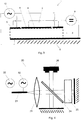
- Fig. 1 shows a preferable embodiment of the laser assembly 1 with a laser 2 with a fast gain medium and a standing wave cavity 3.
- Each end of the standing wave cavity 3, which is a Fabry-Perot cavity, comprises a partially transparent mirror.
- Below the laser assembly is the real part of the spatially dependent complex amplitude 7 of the electrical laser beat-note shown in an idealised schematic as a half-cosine curve from one end of the standing wave cavity 3 to its other end with its extrema at each end. This curve, as well as its higher harmonics, are a result of the boundary conditions in the standing wave cavity 3.
- the laser assembly 1 comprises an electric contact 4, which extends along a first longitudinal side of the standing wave cavity 3, substantially over the whole longitudinal extension of the standing wave cavity 3, and is split into a first electric contact section 5 and a second electric contact section 6 by a nonconducting split in the electric contact 4. Furthermore the laser assembly 1 comprises a grounded substrate 8, extending along a second longitudinal side of the standing wave cavity 3, substantially over the whole longitudinal extension of the standing wave cavity 3 and opposite of the first longitudinal side. Furthermore, the laser assembly 1 comprises a DC source 9 for pumping the laser 2, which is conductively connected to the first electric contact section 5 and to the second electric contact section 6, and an AC injection device 10, which is an RF oscillator and which is conductively connected to the first electric contact section 5.
- the first electric contact section 5 is adjacent to one end of the standing wave cavity 3.
- the injected electrical AC signal is partially matched to the amplitude 7 of the electrical laser beat-note, since it has its maximum absolute value of the complex amplitude close to the end of the standing wave cavity 3, where the spatially dependent amplitude 7 shows a maximum, and is substantially zero everywhere else in the standing wave cavity 3.
- the AC injection device 10 operates at a frequency, which is approximately the round-trip time of the beam in the standing wave cavity 3.
- a frequency which is approximately the round-trip time of the beam in the standing wave cavity 3.
- Fig. 2 shows another embodiment of the laser assembly 1, which in difference to the embodiment of Fig. 1 comprises a first electric contact section 5, a second electric contact section 6 and one further electric contact section 11.
- the electric contact 4 is split into the electric contact section 5, 6, 11 by substantially nonconducting splits in the electric contact 4.
- the DC source is conductively connected to all electric contact sections 5, 6, 11.
- One output of the AC injection device 10 is conductively connected with the first electric contact section 5 and its other, oppositely poled output, is conductively connected to the one further electric contact section 11.
- the first and the one further electric contact section 5, 11, which are both adjacent to different ends of the standing wave cavity 3 are injected an electrical AC signal with the same absolute value of the complex amplitude, but with opposite (i.e.
- the inject electrical AC signal is adjusted to the spatially dependent amplitude 7 of the electrical laser beat-note, which has a phase shift of 180° between both ends of the cavity.
- the AC injection device 10 comprises an RF oscillator and is operated (and suitable for being operated) at a frequency in the proximity of the round-trip time in the standing wave cavity 3.
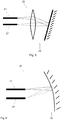
- Fig. 3 shows another preferable embodiment of the laser assembly 1, which also comprises three electric contact sections 5, 6, 11.
- the laser assembly 1 of this embodiment is adopted for injection locking of the second harmonic of the spatially dependent amplitude of the electrical laser beat-note in the standing wave cavity 3.
- the AC injection device which again is an RF oscillator, is conductively connected to the first electric contact section 5 adjacent to one end of the standing wave cavity 3 and to the one further electric contact section 11 adjacent to the other end of the standing wave cavity 3 (without any phase shift, i.e. in the phase).
- the AC injection device is not connected to the second electric contact section 6.
- the first electric contact section 5 and the one further electric contact section 11 receive an electrical AC signal with the same absolute value of the complex amplitude and phase.
- the AC injection device is operating close to the second harmonic of the standing wave cavity roundtrip frequency, i.e. at a frequency in a vicinity of twice the round-trip frequency.
- the spatial profile of the second harmonic is in such a way that the front and rear end of the standing wave cavity 3 can be modulated with the same amplitude and phase.
- Fig. 4 shows an embodiment of a spectrometer 20 comprising a first laser assembly 21 with an AC injection device 10, e.g. one of the embodiments of the laser assembly 1 described above.
- the spectrometer furthermore comprises a modulation oscillator 22 for frequency modulating the AC injection device 10.
- the initial beam emitted from the first laser assembly 21 is collimated by a collimating lens 23 and then split into a first and a second beam by a beam splitter 24.
- the first beam is delayed by a temporally delaying element 25, which is a multipass cell and comprises an interaction zone for interacting the first beam with an analyte, and reflected back to the beam splitter by a mirror.
- the second beam is also reflected back to the beam splitter by a mirror.
- the first beam and the second beam are then combined by a beam combiner, which is the beam splitter 24 (e.g. a semitransparent mirror), onto a detector 26, which has a large enough bandwidth to detect multiheterodyn
- the beating and thus the repetition frequency in the standing wave cavity of the first laser assembly 21 is determined by the frequency of the RF oscillator used for injection locking.
- the temporally delaying element 25 delays the first beam.
- Combining the delayed (first) and the undelayed (second) beam on a detector forms a heterodyne beating, because the delayed light has a slightly different intermodal difference frequency (i.e. the frequency interval between two comb teeth) as the non-delayed light.
- This multiheterodyne beating enables spectroscopic examination of the analyte. It is also possible that the multiheterodyne beating is detected in the laser assembly 21 itself.
- Fig. 5 and Fig. 6 show two embodiment of the spectrometer 20 comprising a first laser assembly 21 and a second laser assembly 27, which differ in the configuration of the optical arrangement 28, which directs and focuses a first beam from an output of the first laser assembly 21 into an output of the second laser assembly 27 and a second beam from the output of the second laser assembly 27 into the output of the first laser assembly 21.
- the optical arrangement 28 comprises a lens and a (tilted) flat mirror
- the optical arrangement 28 comprises a curved mirror.
- An RF spectrum analyzer (not shown) is connected to at least one electric contact section of the first laser assembly 21.
- the embodiments of Fig. 5 and Fig. 6 are particularly easy to be partially or completely implemented on a chip, e.g. using dielectric or plasmonic waveguides instead of free-space optics.
- an external detector it is not necessary for an external detector to be provided for detecting the dual-comb beating of two frequency combs. Instead, as disclosed with this embodiment, it is possible to shine the light of one laser assembly providing a frequency comb into another laser assembly providing a frequency comb and extract the beating directly through one or more electric contact sections used for injecting the electrical AC signal into the standing wave cavity with an RF spectrum analyzer.
- the multiheterodyne beat consists of several narrow lines corresponding to pairs of lines of both frequency combs. However, if one laser should by unlocked by detuning the respective injection frequency, the well-defined lines vanish and only a broad peak without individual lines remains; such an unlocked multiheterodyne beat limits the applicability for spectroscopy purposes. This can be seen in Fig.
- f 0 is the round-trip frequency, which here is approximately 9 GHz.
- Fig. 8 shows an advantageous embodiment of the spectrometer 20 comprising a first laser assembly 21 and a second laser assembly 27.
- a first beam from a first output of the first laser assembly 21 and a second beam from a first output of the second laser assembly 27 are directed into a first detector 29 by a first optical arrangement 30.
- the first optical arrangement 30 also comprises an interaction zone for interacting the first beam with an analyte.
- a third beam from a second output of the first laser assembly 21 and a forth beam from a second output of the second laser assembly 27 are directed into a second detector 31 by a second optical arrangement 32, which contains an interaction zone for interacting the fourth beam with a reference sample.
- the optical arrangement 30, 32 can for example be (on-chip) dielectric or plasmonic waveguides or contain free-space optical elements such as lenses, mirrors and beam-splitters.
- Such a (dual-comb) spectrometer 20 consisting of two lasers assemblies 21, 27 according to any of the laser assemblies disclosed herein and at least one, preferably and in this embodiment two, detectors can easily be integrated on a chip and has the advantage that it is less sensitive against various environmental conditions, e.g. temperature fluctuations. Injection locking of the frequency combs, i.e. operating the laser as disclosed herein, mitigates the effect of strong optical feedback that is omnipresent in on-chip optics.
- the detectors 29, 31 and/or the optical arrangements 30, 32 can be arranged such that the two beams entering each detector 29, 31 enter them from the same direction or from a different/opposite direction. If they are arranged such that the laser light from both laser assemblies 21, 27 enters the detectors 29, 31 from the same side, the stabilization against optical feedback via injection locking allows configurations, where a part of the light focused onto the respective detector 29, 31 is also fed into one or both laser of the laser assemblies 21, 27, e.g. if the laser assemblies 21, 27 and the detectors 29, 31 are spatially close.
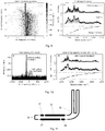
- Fig. 9 illustrates one possible benefit of the invention, namely that coherent injection locking of laser with a high phase-noise to an external AC source as disclosed herein produces a coherent frequency comb with very low phase noise.
- the left subfigure of Fig. 9 shows the microwave spectrum of the optical beat-note of a semiconductor laser frequency comb.
- the laser beat-note of the free-running frequency comb (not visible), i.e. without injection locking or any other stabilization measures, is broad. This is a consequence of relatively large amplitude and phase noise of the comb modes.
- the injected RF power i.e. the power of the AC injection device
- the broad electrical laser beat-note of the (for this Fig.) QCL is pulled towards the injected beat-note.
- the QCL electrical laser beat-note is completely controlled by the injected signal and the broad noise-pedestal disappears.
- a characterization of the frequency comb in this state using "Shifted Wave Interference Fourier Transform Spectroscopy" (SWIFTS) is shown on the right subfigure of Fig. 9 . If the intensity spectrum (plot on the top right) and the SWIFTS spectrum (plot on the center right) overlap on the whole span of the spectrum, this means that the frequency comb is fully coherent on the whole span of the spectrum, which is clearly visible. Furthermore, the characteristic phase profile (plot on the bottom left) ranging from 0 to 2*pi observed also in free-running frequency combs is preserved upon injection of an external AC, in particular RF, signal.
- SWIFTS Shated Wave Interference Fourier Transform Spectroscopy
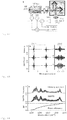
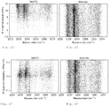
- Fig. 10 illustrates another benefit of the method of operating a laser and the laser assembly as disclosed herein, namely that appropriately injection locked QCL frequency combs are less sensitive against optical feedback.
- QCL frequency combs are very sensitive to optical feedback. This can be seen in the example of the electrical laser beat-note of a QCL frequency comb, in the left subfigure of Fig. 10 .
- the curve with a peak was measured in a configuration, where optical feedback was minimized. It is very narrow and stable, indicating that all modes of the comb are equidistant with very little phase noise.
- the other curve was measured in a configuration, where a polished Si wafer reflected back a considerable portion of the light emitted by the laser.
- the electrical laser beat-note becomes significantly broader and weaker indicating the loss of coherence.
- the right subfigure of Fig. 10 shows plots for a laser operated as disclosed herein, i.e. an appropriately coherently injection locked QCL frequency comb.
- the SWIFTS characterization (plot on the center right) of the electrically injection locked laser in the same configuration as for the measurement of the unstable electrical laser beat-note demonstrates that injection locking is able to mitigate the fatal effect of feedback.
- the laser remains coherent, which is proven by the SWIFTS spectrum.
- the characteristic phase profile ranging from 0 to 2*pi is preserved.
- the stabilization of semiconductor frequency combs against optical feedback is especially important in real-life applications, as optical feedback is omnipresent and limits the versatility and range of application of semiconductor laser frequency combs greatly.
- Fig. 11 shows another advantageous embodiment of the spectrometer 20, similar to the embodiment shown in Fig. 8 , comprising a first laser assembly 21 and a second laser assembly 27.
- the spectrometer 20 of this embodiment is particularly well for being implemented on a chip.
- the first optical arrangement 30 and the second optical arrangement 32 each comprise an optical waveguide integrated on the chip.
- the optical waveguide of first optical arrangement 30 has an optical path length L 1 and the optical waveguide of the second optical arrangement 30 has an optical path length L 2 ⁇ L 1 , such that laser beams being directed through the first optical arrangement 30 interact with an analyte in the vicinity of the spectrometer 20, whereas laser beams being directed through the second optical arrangement 32 do substantially not interact with the analyte in the vicinity of the spectrometer 20.
- an analyte surrounding the chip, on which the spectrometer 20 is implemented can be analyzed and the absorption spectrum be recorded.
- This example shall provide conclusive proof that all teeth of a QCL frequency comb can be locked coherently with an AC injection device, in particular an external RF source, by injecting an electrical AC signal adjusted to the electrical laser beat-note, in particular by applying an RF signal only to one end of the laser (standing wave) cavity.
- an AC injection device in particular an external RF source
- injecting an electrical AC signal adjusted to the electrical laser beat-note in particular by applying an RF signal only to one end of the laser (standing wave) cavity.
- This is the section of the cavity, where the electrical beating is most susceptible to the injected signal due to its inherent spatio-temporal pattern.
- SWIFTS Wave Interference Fourier Transform Spectroscopy'
- QWIP quantum well infrared photodetector
- the complex SWIFTS spectrum in eq. A.1 contains the phase difference of adjacent comb lines. Since only the part of the light locked to the phase reference is measured by the lock-in, the SWIFTS amplitudes are a direct and spectrally resolved measure of the intermodal coherence. If two modes are fully coherent (i.e., phase-locked), the SWIFTS amplitude is commensurate with the geometric average of the amplitudes
- the electrical beatnote is used as phase reference.
- a particularly interesting feature is already conspicuous in the recorded interferograms (see zoom in Fig. 13 ).
- Both SWIFTS quadratures have a minimum at zero-path difference of the FTIR mirrors, whereas the intensity interferogram has its maximum there. This phenomenon is related to the naturally favored comb state in QCLs, where the phases are arranged in a way that minimizes the amplitude of the optical beatnote and thus the amplitude modulation of the laser intensity. This is due to the short sub-ps upper state lifetime in QCL active regions.
- SWIFTS spectrum ( Fig. 14 ) has the same shape as the intensity spectrum without showing any spectral holes. This proves that indeed all teeth of the comb are phase-locked.
- the SWIFTS phases i.e. the phase difference of adjacent comb lines, cover a range of 2 ⁇ from the lowest to the highest frequency mode. This is consistent with the observation of a dominantly frequency modulated output of the QCL with a linearly chirped instantaneous frequency.
- the first challenge to prove coherent injection locking is to show the capability to lock the QCL electrical laser beat-note to the external oscillator.
- Fig. 9 left subfigure
- the broad beatnote is pulled towards the frequency of the injected signal as the RF power is further increased to 5 dBm and finally locks at 8 dBm.
- QCL frequency combs have to withstand harsh conditions while maintaining coherence.
- optical feedback We illustrate the fatal effect of optical feedback on a free-running QCL frequency comb by replacing the attenuating polarizer (POL in Fig. 12 ) by a polished silicon wafer perpendicular to the QCL beam.
- the QCL is subject to both intense static feedback from the Si wafer as well as temporally varying feedback from the QWIP facet due to the scanning FTIR mirrors.
- the electrical beatnote is narrow and stable if the beam is attenuated by the polarizer ( Fig. 10 , left subfigure), it becomes significantly broader and weaker upon exposure to strong optical feedback indicating the loss of coherence.
- the investigated QCL is uncoated and operating at 8 ⁇ m
- the laser has a relatively low group delay dispersion.
- the laser is mounted epi-side-up on a copper submount.
- the temperature of the submount is kept at 15° for all measurements presented using a Peltier element and PTC5000 temperature controller.
- a HP 8341B synthesized sweeper is used for injection locking.
- the RF signal is injected close to the front end of the QCL cavity through 40 GHz two-terminal RF probes. It has to be noted that due to the large parasitic capacitance, the RF signal is strongly damped 30-40dB. In case of an RF optimized device, split contacts are possible to prevent the simultaneous excitation of both ends with the same phase.
- SWIFTS The QWIP used to detect the optical beatnote is fabricated in square mesa geometry with 100 ⁇ m side length. The mesa is connected to a coplanar transmission line with a short wire-bond resulting in a cutoff frequency slightly below 10 GHz. The optical beatnote detected by the QWIP is amplified and mixed down to below 50 MHz. A Zurich Instruments HF2LI lock-in amplifier and the Helium-Neon trigger of the FTIR were used to record the SWIFTS interferograms.
- Eq. A.2 differs slightly from previously published work because the FTIR used here (Bruker Vertex 70v) moves both interferometer arms by ⁇ /2 instead of just one arm by ⁇ .
- Self-detected dual-comb spectrum The two QCLs on the dualcomb chip are roughly 1 mm apart from each other.
- the light emitted from the front facets of the dual-comb chip is collimated using an anti-reflection coated ZnSe lens with 1.5 inch focal length. By aligning a mirror in front of the lens, the light of one laser is reflected into the other.
- the dual-comb beat around 8.7 GHz is extracted directly from the laser using a RF probe and recorded with a spectrum analyzer (acquisition time ⁇ 0.2 s).
- This example shall demonstrate a robust all-electrical technique to generate optical frequency combs in the mid-infrared using ICL. It is shown that ICLs naturally favor FM-type comb operation, the same as has been observed in QCL frequency combs, suggesting that the previous believe that interband cascade lasers possess slow enough gain dynamics that can potentially allow passive mode locking has to be questioned. The facts that ICLs with its large interband lifetime naturally favors repulsive synchronization contradicts simple explanations based on the lifetime of the laser transitions and suggests that other relevant mechanisms have been previously overseen. We also demonstrate that by electric injection locking it is possible to enforce the naturally unfavored in-phase synchronization state. In this actively mode locked regime, the device generates short pulse trains with picosecond pulse widths and serves as a first proof that multiple normal modes can be excited by external modulation.
- SWIFTS shifted wave intermode beat Fourier transform spectroscopy
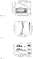
- Fig. 19 shows a sketch of the device with two sections.
- a long section with a thin passivation layer is kept at a constant bias and a shorter section with a thick passivation layer to reduce the parasitic capacity allows efficient RF modulation.
- a first condition of optical frequency operation is the observation of a narrow beat note.
- a narrow beatnote arises when at least a part of the intermode beatings are synchronized (or if two modes dominate the spectrum).
- bias conditions that show a relatively narrow beatnote.
- the waterfall plot showing the beatnote while sweeping the bias around the region of interest is shown in Fig. 20 .
- the spectral width of the beatnote is similar to beatnotes observed in QCL in the so called high phase noise regime.
- a weak RF modulation matched to the observed beatnote frequency round-trip frequency. It can be found that when perfectly matched to the natural beatnote frequency, a modulation as low as -30dBm is sufficient, in order to obtain the intermode phases with SWIFTS.
- the amount of coherence and the intermode phase pattern are shown in Fig. 21 together with a zoom of the recorded interferograms at zero path difference.
- the SWIFTS amplitudes which are a measure of the intermodal coherence, clearly show that frequency comb operation is obtain over the entire emission spectrum.
- the obtained comb state is not a mode-locked state with a short pulse train.
- the particular phase distribution corresponds to a dominantly frequency modulated (FM) waveform and is similar to what has very recently been observed in mid-infrared QCL frequency combs.
- ICLs behave more similar to QCLs in terms of their non-linear temporal dynamics as one might have expected, suggests that the life time of the laser transition is not the main parameter that determines the gain dynamics. Here, we emphasize that it is the way how carriers are injected into the laser levels that governs the fast temporal dynamics in ICLs.
- FIG. 22 sketches the working principle of an ICL. Electron-hole pairs are generated at the so called semi-metallic interface (SMI), which is realized by coupling hole and electron type subbands at a type-II broken gap semiconductor interface. Due to the internal carrier generation no doping is required, although it has been shown that high n-doping in the electron injector can significantly improve the performance of ICLs23.
- SMI semi-metallic interface
- the generated electrons and holes are injected into the upper and lower laser levels via fast intersubband scattering.
- the fast intersubband scattering occurs in both directions, which leads to a fast balancing process between the injectors and the corresponding laser levels.
- the fast intersubband balancing regions are highlighted in Fig. 22 with grey rectangles.
- the interplay of fast injector balancing has three main implications.
- the fast population response occurs via scattering to the injector and not via scattering between the laser levels.
- a large amount of energy can be stored within one round-trip. This is in contrast to QCLs, where the short non-radiative lifetime of the laser transition limits the capability to store energy over one round-trip. This is a main argument why QCLs cannot emit ultra short pulses with peak intensities higher than their continuous continuous wave value.
- the main coupling mechanism responsible for frequency comb formation in fast gain media is four-wave mixing due to population pulsations, which leads to a phase sensitive coherent loss mechanism. Because of its similarity to oscillator arrays with repulsive global mean-field coupling, it should be related to repulsive mean-field coupling with the population pulsation being the mean-field.
- Single-mode instability in standing-wave lasers The quantum cascade laser as a self-pumped parametric oscillator.” in Phys. Rev.
- a 94 (2016 ), the population pulsation at the difference frequency between the center mode its weak side modes will result in a parametric gain contribution with a negative sign, thus referred to as parametric suppression.
- the total gain of each sideband consists of the Lorentzian shaped gain of the two-level system, incoherent gain due to spatial hole burning, plus a negative parametric contribution due to population pulsation.
- FM type the two contributions balance each other and the population pulsation remains zero. This state sees more gain and is thus favored among the in-phase (amplitude modulate, AM) state.
- AM amplitude modulate
- each pair of laser lines results in a beating at its difference frequency. Not yet being phase locked, each pair beats at slightly different frequency due to the cavity dispersion, i.e. each pair sees a different round-trip frequency.
- oscillators that are globally coupled trough the population pulsation. If the dispersion is low enough and the coupling is sufficiently large, the oscillators can synchronize. As the coupling is of repulsive type the phases will be chosen in a very particular manner, such that the mean-field (population pulsation) is minimized.
- phase balance states States that minimize the mean-field oscillation are commonly referred to as phase balance states and have been studied in many different fields, ranging from splay states in Josephson junctions to cluster states in complex networks. The more oscillators are coupled, the more balance states can exist. It is the stability that determines if a state can be observed. It was shown that more complex couplings, e.g. higher harmonic couplings can reduce the number of favored balances states. Harmonic FM waveforms as those described by Bessel functions were initially believed to be the naturally favored comb state in QCLs, however, they are only one out of many possible phase balance states and have not been observed in experiments.
- Fig. 24 illustrates the unlocked state, in-phase synchronization, that would lead to periodic short pulse emission, and the particular repulsive synchronization pattern observed in ICL and QCL frequency combs.
- balancing is also achieved for higher harmonic intermode beatings, where the phase pattern for the nth harmonic approximately follows a phase distribution from 0 to 2 ⁇ *n.
- group velocity dispersion GVD
- Fig. 24 illustrates the unlocked state, in-phase synchronization, that would lead to periodic short pulse emission, and the particular repulsive synchronization pattern observed in ICL and QCL frequency combs.
- GVD group velocity dispersion
- FIG. 25 shows the optical beatnote while sweeping the injection frequency for three different weak injection power levels, showing the expected scaling of the locking range with power.
- SWIFTS allows the reconstruction of the time domain signal, which is shown in Fig. 27 .
- the instantaneous frequency shows a saw-tooth shape, sweeping over the spectral range within one round-trip. This behavior exactly matches, what has been recently observed in QCLs.
- the signal is dominantly amplitude modulated, its phase pattern remains determined by repulsive synchronization. This means, that the internal coupling tries to splay the phases and that the narrowing is only due to the strong externally enforced modulation of the mean-field. As a result, the time domain signal does not show short pulse formation, but its envelop tries follows the external modulation.
- ICLs are fast gain media and share more properties with QCLs than previously expected.
- carriers are injected via fast intersubband transtions from an injector region, which makes them fundamentally different to other types of lasers.
- fast carrier balancing between the laser levels and the injector is responsible for the fast gain dynamics in ICLs.
- weak external synchronization we are able to obtain robust frequency comb operation in ICLs for the first time with a suffi-cient proof. A very particular phase pattern has been observed, which is similar to that recently found in QCL frequency combs.
- the laser ridges were fabricated with standard mask photolithography, reactive ion etching to device the laser waveguides, silicon nitride for the passivation layers and sputtered TiAu for the contact pads.
- the substrate was thinned to 160 ⁇ m and TiAu was sputtered on the backside and the devices were mounted epi-side up using indium on a copper mount. Different thickness of the passivation layer have been used to optimize the device performance in terms of output power and modulation capability.
- Measurement setup The devices were mounted on a copper submount, thermo-electrically stabilized to 15C. In order to improve the noise properties of our laser driver, we used home-build filters. The accuracy of temperature stabilization and the noise of the laser drivers play a crucial role for the performed measurements.
- SWIFTS The SWIFTS concept was realized using a fast QWIP placed at the output window of a FTIR.
- the emitted light of the ICL is shined through the FTIR onto the QWIP.
- a local oscillator mixes down the QWIP signal to ⁇ 40 MHz.
- the quadrature components X and Y of the QWIP signal in dependence of the delay time ⁇ gives us two correlating interferograms for the RF locked part of each quadrature component and were measured using a lock-in amplifier.
- the reference signal is obtained by mixing of a local oscillator with the RF source. All interferograms were recorder by the locki-in using the trigger from the FTIR. Note, that our used FTIR moves each arm by ⁇ /2.
Landscapes
- Physics & Mathematics (AREA)
- General Physics & Mathematics (AREA)
- Optics & Photonics (AREA)
- Condensed Matter Physics & Semiconductors (AREA)
- Electromagnetism (AREA)
- Spectroscopy & Molecular Physics (AREA)
- Chemical & Material Sciences (AREA)
- Life Sciences & Earth Sciences (AREA)
- Health & Medical Sciences (AREA)
- Analytical Chemistry (AREA)
- Biochemistry (AREA)
- General Health & Medical Sciences (AREA)
- Immunology (AREA)
- Pathology (AREA)
- Semiconductor Lasers (AREA)
- Investigating Or Analysing Materials By Optical Means (AREA)
Priority Applications (4)
| Application Number | Priority Date | Filing Date | Title |
|---|---|---|---|
| EP18188432.1A EP3609028A1 (de) | 2018-08-10 | 2018-08-10 | Laseranordnung, spektrometer und verfahren zum betrieb eines lasers |
| EP19749741.5A EP3834259A1 (de) | 2018-08-10 | 2019-08-09 | Laseranordnung, spektrometer und verfahren zum betrieb eines lasers |
| PCT/EP2019/071387 WO2020030772A1 (en) | 2018-08-10 | 2019-08-09 | Laser assembly, spectrometer and method for operating a laser |
| US17/266,374 US11916354B2 (en) | 2018-08-10 | 2019-08-09 | Laser assembly, spectrometer and method for operating a laser |
Applications Claiming Priority (1)
| Application Number | Priority Date | Filing Date | Title |
|---|---|---|---|
| EP18188432.1A EP3609028A1 (de) | 2018-08-10 | 2018-08-10 | Laseranordnung, spektrometer und verfahren zum betrieb eines lasers |
Publications (1)
| Publication Number | Publication Date |
|---|---|
| EP3609028A1 true EP3609028A1 (de) | 2020-02-12 |
Family
ID=63209251
Family Applications (2)
| Application Number | Title | Priority Date | Filing Date |
|---|---|---|---|
| EP18188432.1A Withdrawn EP3609028A1 (de) | 2018-08-10 | 2018-08-10 | Laseranordnung, spektrometer und verfahren zum betrieb eines lasers |
| EP19749741.5A Pending EP3834259A1 (de) | 2018-08-10 | 2019-08-09 | Laseranordnung, spektrometer und verfahren zum betrieb eines lasers |
Family Applications After (1)
| Application Number | Title | Priority Date | Filing Date |
|---|---|---|---|
| EP19749741.5A Pending EP3834259A1 (de) | 2018-08-10 | 2019-08-09 | Laseranordnung, spektrometer und verfahren zum betrieb eines lasers |
Country Status (3)
| Country | Link |
|---|---|
| US (1) | US11916354B2 (de) |
| EP (2) | EP3609028A1 (de) |
| WO (1) | WO2020030772A1 (de) |
Cited By (2)
| Publication number | Priority date | Publication date | Assignee | Title |
|---|---|---|---|---|
| JPWO2022118647A1 (de) * | 2020-12-04 | 2022-06-09 | ||
| US11629997B2 (en) | 2020-11-06 | 2023-04-18 | Irsweep Ag | Dual-comb spectroscopy |
Families Citing this family (2)
| Publication number | Priority date | Publication date | Assignee | Title |
|---|---|---|---|---|
| US12055604B1 (en) * | 2023-07-05 | 2024-08-06 | Deuve Photonics, Inc. | Stabilization of laser-based sensors |
| CN119787077B (zh) * | 2024-12-25 | 2026-04-14 | 南京理工大学 | 基于谷值功率锁定的半外腔线偏振干涉光源及其设计方法 |
Family Cites Families (1)
| Publication number | Priority date | Publication date | Assignee | Title |
|---|---|---|---|---|
| US6653662B2 (en) * | 2000-11-01 | 2003-11-25 | Matsushita Electric Industrial Co., Ltd. | Semiconductor light-emitting device, method for fabricating the same, and method for driving the same |
-
2018
- 2018-08-10 EP EP18188432.1A patent/EP3609028A1/de not_active Withdrawn
-
2019
- 2019-08-09 EP EP19749741.5A patent/EP3834259A1/de active Pending
- 2019-08-09 US US17/266,374 patent/US11916354B2/en active Active
- 2019-08-09 WO PCT/EP2019/071387 patent/WO2020030772A1/en not_active Ceased
Non-Patent Citations (7)
| Title |
|---|
| CHRISTINE Y WANG ET AL: "Mode-locked pulses from mid-infrared Quantum Cascade Lasers", OPTICS EXPRESS, vol. 17, no. 15, 13 July 2009 (2009-07-13), pages 12929 - 12943, XP055549621 * |
| DERICKSON ET AL.: "Short Pulse Generation Using Multisegment Mode-Locked Semiconductor Lasers", IEEE JOURNAL OF QUANTUM ELECTRONICS, vol. 28, no. 10, 1992, XP002975392, DOI: doi:10.1109/3.159527 |
| HUGI ET AL.: "Mid-infrared frequency comb based on a quantum cascade laser", NATURE, vol. 492, 2012, pages 229 - 233 |
| MANSURIPUR ET AL.: "Single-mode instability in standing-wave lasers: The quantum cascade laser as a self-pumped parametric oscillator", PHYS. REV. A, vol. 94, 2016 |
| MARCO PICCARDO ET AL: "Time-dependent population inversion gratings in laser frequency combs", OPTICA, vol. 5, no. 4, 17 April 2018 (2018-04-17), pages 475, XP055549156, DOI: 10.1364/OPTICA.5.000475 * |
| PICCARDO ET AL.: "Time-dependent population inversion gratings in laser frequency combs", OPTICA, vol. 5, no. 4, April 2018 (2018-04-01) |
| WANG YIN ET AL: "High-resolution multi-heterodyne spectroscopy based on Fabry-Perot quantum cascade lasers", APPLIED PHYSICS LETTERS, A I P PUBLISHING LLC, US, vol. 104, no. 3, 20 January 2014 (2014-01-20), XP012181072, ISSN: 0003-6951, [retrieved on 19010101], DOI: 10.1063/1.4862756 * |
Cited By (5)
| Publication number | Priority date | Publication date | Assignee | Title |
|---|---|---|---|---|
| US11629997B2 (en) | 2020-11-06 | 2023-04-18 | Irsweep Ag | Dual-comb spectroscopy |
| US11650101B2 (en) | 2020-11-06 | 2023-05-16 | Irsweep Ag | Dual-comb spectroscopy |
| US11796392B2 (en) | 2020-11-06 | 2023-10-24 | Irsweep Ag | Dual-comb spectroscopy |
| JPWO2022118647A1 (de) * | 2020-12-04 | 2022-06-09 | ||
| WO2022118647A1 (ja) * | 2020-12-04 | 2022-06-09 | パナソニックホールディングス株式会社 | 光周波数コム装置および計測装置 |
Also Published As
| Publication number | Publication date |
|---|---|
| WO2020030772A1 (en) | 2020-02-13 |
| US11916354B2 (en) | 2024-02-27 |
| EP3834259A1 (de) | 2021-06-16 |
| US20210313775A1 (en) | 2021-10-07 |
Similar Documents
| Publication | Publication Date | Title |
|---|---|---|
| JP7248370B2 (ja) | 小型微小共振器周波数コム | |
| US8792524B2 (en) | Arbitrary optical waveform generation utilizing optical phase-locked loops | |
| Wang et al. | High-resolution multi-heterodyne spectroscopy based on Fabry-Perot quantum cascade lasers | |
| US11916354B2 (en) | Laser assembly, spectrometer and method for operating a laser | |
| Sterczewski et al. | Frequency-modulated diode laser frequency combs at 2 μm wavelength | |
| EP3097614B1 (de) | Optische quelle mit dualer frequenz | |
| US8289523B2 (en) | Method and device for generating a synthetic wavelength | |
| Tani et al. | Generation of coherent terahertz radiation by photomixing of dual-mode lasers | |
| Paschotta et al. | Noise of solid-state lasers | |
| CN103444020A (zh) | 用于oct医学成像的具有受控锁模的激光扫频源 | |
| Teshima et al. | Experimental investigation of injection locking of fundamental and subharmonic frequency-modulated active mode-locked laser diodes | |
| FR2958809A1 (fr) | Methode de stabilisation de la frequence d'emission d'un laser a cascade quantique, dispositif associe | |
| Zhang et al. | Frequency modulated and polarization maintaining fiber laser with narrow linewidth | |
| Kurosu et al. | Diode laser spectrometer for high-resolution spectroscopy in the visible range | |
| Jiang et al. | Period-Two Dynamics of an Optically Injected Semiconductor Laser for Range-Sensitive Resonance Detection | |
| Skehan | Low Noise Frequency Combs and their Use in Broadly Tunable Lasers and Optical Coherence Tomography | |
| Fedderwitz | Generation of Frequency Tunable and Low Phase Noise Micro-and Millimeter-Wave Signals using Photonic Technologies | |
| Torabifard | Transfer Cavity Stabilization Using the Pound-Drever-Hall Technique with Noise Cancellation | |
| WO2008129492A2 (en) | Method and device for determining a phase relation between optical fields and radiofrequency or microwave fields | |
| Anderson et al. | Frequency modulation characteristics of laser diodes in external cavities | |
| Acedo Gallardo et al. | Photonic synthesis of continuous-wave millimeter-wave signals using a passively mode-locked laser diode and selective optical filtering | |
| Yilmaz | Modelocked external-cavity semiconductor laser noise characterization and application to photonic arbitrary waveform generation | |
| HOLLBERG et al. | High-Accuracy Spectroscopy with Semiconductor Lasers: Application to Laser | |
| Williams | Injection Locking Of Semiconductor Mode-locked Lasers For Long-term Stability Of Widely Tunable Frequency Combs | |
| Criado Serrano et al. | Continuous wave sub-THz photonic generation with ultra-narrow linewidth, ultra-high resolution, full frequency range coverage and high long-term frequency stability |
Legal Events
| Date | Code | Title | Description |
|---|---|---|---|
| PUAI | Public reference made under article 153(3) epc to a published international application that has entered the european phase |
Free format text: ORIGINAL CODE: 0009012 |
|
| STAA | Information on the status of an ep patent application or granted ep patent |
Free format text: STATUS: THE APPLICATION HAS BEEN PUBLISHED |
|
| AK | Designated contracting states |
Kind code of ref document: A1 Designated state(s): AL AT BE BG CH CY CZ DE DK EE ES FI FR GB GR HR HU IE IS IT LI LT LU LV MC MK MT NL NO PL PT RO RS SE SI SK SM TR |
|
| AX | Request for extension of the european patent |
Extension state: BA ME |
|
| STAA | Information on the status of an ep patent application or granted ep patent |
Free format text: STATUS: THE APPLICATION IS DEEMED TO BE WITHDRAWN |
|
| 18D | Application deemed to be withdrawn |
Effective date: 20200813 |