EP3608835A1 - Verfahren zum verarbeiten von fingerabdruckbildern - Google Patents
Verfahren zum verarbeiten von fingerabdruckbildern Download PDFInfo
- Publication number
- EP3608835A1 EP3608835A1 EP19189722.2A EP19189722A EP3608835A1 EP 3608835 A1 EP3608835 A1 EP 3608835A1 EP 19189722 A EP19189722 A EP 19189722A EP 3608835 A1 EP3608835 A1 EP 3608835A1
- Authority
- EP
- European Patent Office
- Prior art keywords
- region
- image
- representative
- regions
- child
- Prior art date
- Legal status (The legal status is an assumption and is not a legal conclusion. Google has not performed a legal analysis and makes no representation as to the accuracy of the status listed.)
- Granted
Links
Images



Classifications
-
- G—PHYSICS
- G06—COMPUTING OR CALCULATING; COUNTING
- G06T—IMAGE DATA PROCESSING OR GENERATION, IN GENERAL
- G06T7/00—Image analysis
- G06T7/10—Segmentation; Edge detection
- G06T7/187—Segmentation; Edge detection involving region growing; involving region merging; involving connected component labelling
-
- G—PHYSICS
- G06—COMPUTING OR CALCULATING; COUNTING
- G06T—IMAGE DATA PROCESSING OR GENERATION, IN GENERAL
- G06T5/00—Image enhancement or restoration
- G06T5/20—Image enhancement or restoration using local operators
- G06T5/30—Erosion or dilatation, e.g. thinning
-
- G—PHYSICS
- G06—COMPUTING OR CALCULATING; COUNTING
- G06T—IMAGE DATA PROCESSING OR GENERATION, IN GENERAL
- G06T7/00—Image analysis
- G06T7/10—Segmentation; Edge detection
- G06T7/11—Region-based segmentation
-
- G—PHYSICS
- G06—COMPUTING OR CALCULATING; COUNTING
- G06T—IMAGE DATA PROCESSING OR GENERATION, IN GENERAL
- G06T7/00—Image analysis
- G06T7/10—Segmentation; Edge detection
- G06T7/155—Segmentation; Edge detection involving morphological operators
-
- G—PHYSICS
- G06—COMPUTING OR CALCULATING; COUNTING
- G06T—IMAGE DATA PROCESSING OR GENERATION, IN GENERAL
- G06T7/00—Image analysis
- G06T7/10—Segmentation; Edge detection
- G06T7/194—Segmentation; Edge detection involving foreground-background segmentation
-
- G—PHYSICS
- G06—COMPUTING OR CALCULATING; COUNTING
- G06V—IMAGE OR VIDEO RECOGNITION OR UNDERSTANDING
- G06V10/00—Arrangements for image or video recognition or understanding
- G06V10/20—Image preprocessing
- G06V10/26—Segmentation of patterns in the image field; Cutting or merging of image elements to establish the pattern region, e.g. clustering-based techniques; Detection of occlusion
- G06V10/267—Segmentation of patterns in the image field; Cutting or merging of image elements to establish the pattern region, e.g. clustering-based techniques; Detection of occlusion by performing operations on regions, e.g. growing, shrinking or watersheds
-
- G—PHYSICS
- G06—COMPUTING OR CALCULATING; COUNTING
- G06V—IMAGE OR VIDEO RECOGNITION OR UNDERSTANDING
- G06V10/00—Arrangements for image or video recognition or understanding
- G06V10/40—Extraction of image or video features
- G06V10/52—Scale-space analysis, e.g. wavelet analysis
-
- G—PHYSICS
- G06—COMPUTING OR CALCULATING; COUNTING
- G06V—IMAGE OR VIDEO RECOGNITION OR UNDERSTANDING
- G06V40/00—Recognition of biometric, human-related or animal-related patterns in image or video data
- G06V40/10—Human or animal bodies, e.g. vehicle occupants or pedestrians; Body parts, e.g. hands
- G06V40/12—Fingerprints or palmprints
- G06V40/13—Sensors therefor
- G06V40/1306—Sensors therefor non-optical, e.g. ultrasonic or capacitive sensing
-
- G—PHYSICS
- G06—COMPUTING OR CALCULATING; COUNTING
- G06V—IMAGE OR VIDEO RECOGNITION OR UNDERSTANDING
- G06V40/00—Recognition of biometric, human-related or animal-related patterns in image or video data
- G06V40/10—Human or animal bodies, e.g. vehicle occupants or pedestrians; Body parts, e.g. hands
- G06V40/12—Fingerprints or palmprints
- G06V40/1347—Preprocessing; Feature extraction
-
- G—PHYSICS
- G06—COMPUTING OR CALCULATING; COUNTING
- G06T—IMAGE DATA PROCESSING OR GENERATION, IN GENERAL
- G06T2207/00—Indexing scheme for image analysis or image enhancement
- G06T2207/20—Special algorithmic details
- G06T2207/20016—Hierarchical, coarse-to-fine, multiscale or multiresolution image processing; Pyramid transform
-
- G—PHYSICS
- G06—COMPUTING OR CALCULATING; COUNTING
- G06T—IMAGE DATA PROCESSING OR GENERATION, IN GENERAL
- G06T2207/00—Indexing scheme for image analysis or image enhancement
- G06T2207/30—Subject of image; Context of image processing
- G06T2207/30196—Human being; Person
Definitions
- the invention relates to a method for processing an image representative of a plurality of fingers supplied by a thin film transistor type image sensor of a fingerprint capture system and a device implementing the method. .
- fingerprints for example of the fingerprint type, of a plurality of fingers, of a palm, makes it possible to secure accesses to buildings or to machines. Using this technology increases security since the probability that two people will have two identical fingerprints is almost zero.
- a fingerprint capture system allows you to capture an image of a fingerprint.
- this fingerprint is compared with a set of reference fingerprints contained in a database.
- this fingerprint is compared to a single fingerprint. The comparison makes it possible to determine whether or not the captured fingerprint belongs to a person referenced in the database or if the person is who he claims to be.
- CCD and CMOS sensors provide images with specific properties (distributions of gray levels or values of color components, resolution, absence of artefacts, etc.) than algorithms for image processing, recognition or compression take into account during their processing. These treatments would be largely unsuitable if they had to process images with different properties. For example, these algorithms would unable to process images provided by sensors using different technology such as TCM type sensors (thin film transistors (TFT) in English terminology), called TCM sensors.
- TCM type sensors thin film transistors (TFT) in English terminology
- a finger when a finger is placed on a fingerprint capture system using a TCM sensor, called a TCM system, the finger appears in the image supplied by this sensor with gray levels inverted compared to a supplied image.
- a fingerprint capture system using a CCD or CMOS sensor called CCD / CMOS system.
- CCD / CMOS system a fingerprint capture system using a CCD or CMOS sensor
- drop shadows appear in the vicinity of the finger, which is not the case with a CCD / CMOS system.
- the invention relates to a method of processing an image representative of at least one finger supplied by an image sensor of the thin film transistor type of a fingerprint capture system. digital, said system comprising a transparent blade comprising a face on which each finger is placed and said image sensor is positioned so as to generate an image of each finger.
- the method comprises: obtaining an image of each finger supplied by the image sensor, called the first image; obtaining a second image by removing each continuous component from the first image; obtaining a third image by applying an averaging filter to the second image; applying a related component analysis to the third image to define regions in said third image, each region comprising pixels having an identical value, called a representative value; organize the regions in the form of a hierarchical tree in which the regions are organized according to a parent-child relationship, a first region being a parent of a second region, which is then a child of the first region, when at least one pixel of the second region is close to a pixel of the first region and that a difference between the values representative of the first and second regions is smaller than a difference between the values representative of the first region and all other regions having at least one pixel neighboring a pixel of the first region, the child region having a lower representative value than its parent region; browse the hierarchical tree in order of increasing representative values and agglomerate each child region with its parent region
- the image obtained by applying the method of the invention to an image from a thin film transistor type sensor then has properties in accordance with the image properties provided by a CCD or CMOS sensor.
- the characteristics of the images obtained by this method then conform to the characteristics of images expected by image processing methods adapted to images from CCD or CMOS sensors. Furthermore, the organization according to a hierarchical tree and the course of this hierarchical tree during the formation of the regions, makes it possible to determine several regions in parallel and thus to process images representing a plurality of fingers.
- the method comprises applying morphological erosion to the agglomerated regions and applying at least one morphological expansion to the regions obtained by morphological erosion as long as each region obtained by morphological erosion remains independent, the determination of each convex envelope being made on each agglomerated region after erosion and morphological dilation.
- Erosion and then expansion make it possible to segment regions comprising a plurality of fingerprints into several regions each comprising a fingerprint.
- the method comprises applying processing to the values of the pixels of the fourth image included in each convex envelope so that these pixels have values lying within a range of predetermined values.
- a predetermined criterion is based on an evolution of the areas of regions resulting from the agglomeration and / or on a comparison of a gradient value representative of the parent region to be agglomerated with at least one child region with a predetermined gradient threshold.
- the gradient representative of the parent region is calculated between the value representative of the parent region and the lowest value representative of a region of the third image, agglomeration being accepted when said gradient is greater than the predetermined gradient threshold.
- the invention relates to a device for processing an image representative of at least one finger supplied by an image sensor of the thin film transistor type of a fingerprint capture system. digital, said system comprising a transparent blade comprising a face on which each finger is placed and said image sensor is positioned so as to generate an image of each finger.
- the device comprises: means for obtaining an image of each finger supplied by the image sensor, called the first image; filtering means for obtaining a second image by removing each continuous component from the first image; filtering means for obtaining a third image by applying an averaging filter to the second image; processing means for applying a related component analysis to the third image in order to define regions in said third image, each region comprising pixels having an identical value, called representative value; processing means for organizing the regions in the form of a hierarchical tree in which the regions are organized according to a parent-child relationship, a first region being a parent of a second region, which is then a child of the first region, when at at least one pixel from the second region is close to a pixel from the first region and a difference between the values representative of the first and second regions is less than a difference between the values representative of the first region and all other regions having at least one pixel neighboring a pixel of the first region, the child region having a lower representative value than its parent region; processing means for browsing the hierarchical tree
- the invention relates to a computer program comprising instructions for implementing, by a device, the method according to the first aspect, when said program is executed by a processor of said device.
- the invention relates to storage means, storing a computer program comprising instructions for implementing, by a device, the method according to the first aspect, when said program is executed by a processor of said device.
- the method of the invention is described in a context where a system for capturing fingerprints using a thin film transistor type sensor acquires images of a plurality of fingers.
- the invention is however suitable for operating on images comprising only one finger. It then makes it possible to obtain images of a finger having properties identical to the properties of images acquired by a fingerprint capture system using a CCD or CMOS sensor.
- the Fig. 1 schematically describes an example of a fingerprint capture system using the method according to the invention.
- a plurality of fingers of one hand M is placed on a fingerprint capture system 10.
- the Fig. 2 schematically illustrates in detail the fingerprint capture system 10.
- the fingerprint capture system 10 comprises a transparent blade 100 comprising an upper face on which the plurality of fingers is placed, of which only one finger D is shown in the Fig. 2 .
- the fingerprint capture system Located below the transparent blade 100 and glued to the underside of said blade, the fingerprint capture system comprises a thin film transistor type image sensor, called the TCM 101 sensor.
- the TCM 101 sensor is positioned so as to generate an image of the plurality of fingers.
- the fingerprint capture system 10 further comprises a processing module 102.
- the Fig. 3 schematically illustrates an example of hardware architecture of the processing module 102.
- the processing module 102 then comprises, connected by a communication bus 1020: a processor or CPU ("Central Processing Unit” in English) 1021; a random access memory RAM (“Random Access Memory” in English) 1022; a read only memory ROM (“Read Only Memory” in English) 1023; a storage unit such as a hard disk or a storage medium reader, such as an SD card reader (“Secure Digital” in English) 1024; at least one communication interface 1025 allowing the processing module 102 to receive the images acquired by the image sensor 101.
- a communication bus 1020 a processor or CPU (“Central Processing Unit” in English) 1021; a random access memory RAM (“Random Access Memory” in English) 1022; a read only memory ROM (“Read Only Memory” in English) 1023; a storage unit such as a hard disk or a storage medium reader, such as an SD card reader (“Secure Digital” in English) 1024; at least one communication interface 1025 allowing the processing module 102 to receive the images acquired by the image sensor 101.
- Processor 1021 is capable of executing instructions loaded into RAM 1022 from ROM 1023, from external memory (not shown), from a medium storage (such as an SD card), or a communications network. When the processing module 102 is powered up, the processor 1021 is able to read and execute instructions from RAM 1022. These instructions form a computer program causing the implementation, by the processor 1021, of the method described in relation to the Fig. 4 .
- the process described in relation to the Fig. 4 can be implemented in software form by execution of a set of instructions by a programmable machine, for example a DSP ("Digital Signal Processor” in English), a microcontroller or a GPU (graphics processor, "Graphics Processing Unit” in terminology or be implemented in hardware form by a dedicated machine or component, for example an FPGA ("Field-Programmable Gate Array” in English) or an ASIC ("Application-Specific Integrated Circuit" in English).
- a programmable machine for example a DSP ("Digital Signal Processor” in English
- a microcontroller or a GPU graphics processor, "Graphics Processing Unit” in terminology or be implemented in hardware form by a dedicated machine or component, for example an FPGA ("Field-Programmable Gate Array” in English) or an ASIC ("Application-Specific Integrated Circuit” in English).
- FPGA Field-Programmable Gate Array
- ASIC Application-Specific Integrated Circuit
- the Fig. 4 schematically illustrates an example of a method for processing an image representative of at least one finger supplied by an image sensor of the thin film transistor type.
- the processing module 102 obtains a first image of the TCM sensor 101.
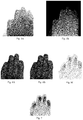
- An example of an image of a plurality of fingers provided by the TCM sensor 101 is represented by the Fig. 5A .
- the parts of the plurality of fingers in contact with the upper face of the transparent blade 100 appear in dark gray.
- the valleys of the fingerprints of the plurality of fingers appear in light gray, even in white.
- Drop shadows appear near the fingers.
- the Fig. 5B represents the image of the Fig. 5A after inverting the gray levels. We realize that a simple inversion of the gray levels does not make it possible to obtain an exploitable image. Indeed, the shadows cast are always present and have only changed the gray level. The presence of drop shadows prevents proper identification of each finger and can create false fingerprint minutiae.
- the processing module 102 deletes each continuous component from the first image in order to obtain a second image.
- a continuous component in an image appears as a uniform area.
- the processing module 102 applies a high pass filter to the first image to obtain the second image.
- the second image is obtained by the processing module 102 by applying a top-hat filter as described in the document “ PT Jackway, improved morphological top-hat ", Electronics Letters, Vol: 36, Issue: 14, 6 July 2000 ) " At the first image to delete each continuous component.
- Applying a top-hat filter to an initial image consists in applying a morphological closure to said initial image and then in calculating a difference between the initial image and the image resulting from the morphological closure.
- FIG. 6A represents an image of a plurality of fingers supplied by a TCM sensor, called the original image, used at the input of a top-hat filter.
- the Fig. 6B represents a result of applying a morphological closure to the original image.
- the Fig. 6C represents a result of applying a top-hat filter to the original image.
- the pixels corresponding to the peaks of the fingerprints appear in dark gray while the pixels corresponding to the valleys appear in light gray, which corresponds to the desired characteristics of the images.
- these interesting pixels are embedded among pixels offering little or no interest for fingerprint recognition. The rest of the process makes it possible to eliminate pixels which are of no interest for the recognition of fingerprints.
- the processing module 102 obtains a third image by applying an averaging filter to the second image.
- An averaging filter replaces each pixel to be filtered with an average calculated from the value of said pixel and the values of neighboring pixels of said pixel.
- the Fig. 7 represents an image corresponding to an application of an averaging filter to the image of the Fig. 6C ( ie in the second image).
- the processing module 102 applies an analysis in components connected to the third image in order to define regions in said third image, each region consisting of pixels having an identical value, hereinafter called representative value.
- a related component analysis applied to an image consists in scanning the pixels of said image, and in giving a label to each pixel. Two neighboring pixels which have the same value are considered to belong to the same region and therefore have the same label. Two neighboring pixels which do not have the same value do not belong to the same region and therefore have different labels.
- the processing module 102 organizes the regions obtained in the form of a hierarchical tree in which the regions are organized according to a parent-child relationship.
- a first region is a parent of a second region, which is then a child of the first region, when at least one pixel of the second region is close to a pixel of the first region and a difference between the representative values of the first and second regions is smaller than a difference between the representative values of the first region and all other regions having at least one pixel neighboring a pixel of the first region.
- the pixels corresponding to the areas of the plurality of fingers most pressed on the upper face of the transparent strip, that is to say corresponding in particular to the crests of the fingerprints are the darkest pixels.
- a dark pixel corresponds to a low gray level value (ie close to "0") while a bright pixel corresponds to a high gray level value ( ie close to "255" for grayscale coded on "8" bits).
- a child region has a representative value (that is to say, the common value of each pixel constituting this region) lower than its parent region.
- the hierarchical tree therefore includes leaves ( ie regions without children) corresponding to the darkest regions.
- the organization of the regions in the form of a hierarchical tree is based for example on a method described in the document " Yongchao Xu, Tree-based shape spaces: definition and applications in image processing and computer vision, liable Paris-Est, 2013 ".
- the Fig. 13A represents an image comprising a set of regions obtained by analysis in connected components of a gray level image.
- the gray level of each region in the Fig. 13A corresponds to the representative value of said region.
- the regions 130 and 134 are the darkest regions and therefore associated with the lowest representative value.
- the region 139 which corresponds to the background of the image of the Fig. 13A is the clearest region and therefore associated with the highest representative value.
- the Fig. 13B corresponds to a hierarchical tree representation of the image of the Fig. 13A .
- the leaves of the tree are made up of regions 130 and 134.
- the root of the tree is made up of region 139.
- the leaf 130, the nodes 131 to 133 and 138 and the root 139 are organized in order of increasing representative values .
- the leaf 134, the nodes 135 to 137 and 138 and the root 139 are organized in order of increasing representative values.
- the hierarchical tree obtained comprises a branch A and a branch B.
- Agglomerating a child region with a parent region consists in determining an agglomerated region corresponding to a union of the parent and child regions.
- the processing module 102 traverses the hierarchical tree in order of increasing representative values and agglomerates a child region with its parent region when at least one predetermined criterion is met.
- a first predetermined criterion is based on an evolution of an area of the regions resulting from the agglomeration. This criterion is based on the assumption that, after the agglomeration of a child region with its parent region, the area of the agglomerated region has greatly increased compared to the area of the child region, then the agglomerated region encompasses several fingers.
- the processing module 102 calculates a percentage increase p of the area of the agglomerated region relative to the area of the child region and compares this percentage increase p with a percentage increase predetermined P.
- a parent region is not agglomerated with a child region if the percentage of increase p is greater than the percentage of predetermined increase P.
- Agglomeration of a child region with its parent region is authorized when the growth coefficient C is less than or equal to a predetermined threshold CMAX. If the growth coefficient C is greater than the predetermined threshold CMAX, agglomeration is not authorized and the child region is considered as a final region.
- the predetermined threshold CMAX is for example equal to "150".
- the child region 130 can be agglomerated with its parent region 131 since the growth coefficient C is less than the predetermined threshold CMAX for this agglomeration. The region resulting from this agglomeration then becomes a child of region 132. For the same reason, agglomeration with regions 132 then 133 is authorized.
- the growth coefficient C being greater than the predetermined threshold CMAX for the agglomeration with region 138, this agglomeration is not authorized.
- the agglomeration for branch A of the hierarchical tree stops and the region resulting from the agglomerations of regions 130 to 133 becomes final.
- the final region for branch B results from the agglomerations of regions 134 to 137.
- a second predetermined criterion is based on a comparison of a gradient value g representative of the parent region to be agglomerated with at least one child region with a predetermined gradient threshold G.
- a parent region is agglomerated with a child region if the gradient g between the value representative of this parent region with the lowest value representing region of the third image is greater than the predetermined gradient threshold G.
- the predetermined gradient threshold is for example equal to "5".
- region 138 could not have been agglomerated with the region resulting from the agglomerations of regions 130 to 133 because the gradient g between region 138 and region 139 is less than the predetermined gradient threshold G.
- Agglomeration as a function of the gradient makes it possible not to not take into account regions with a very low gradient which would be generated by latents left by previous finger applications on the upper face of the transparent blade 100.
- processing module 102 uses the first and / or the second criterion.
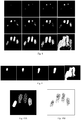
- the Fig. 8 represents a succession of images illustrating a formation of regions in the third image using the hierarchical tree.
- the representative values of the regions have been inverted. So the brightest regions in the pictures of the Fig. 8 correspond to the darkest areas in the third image and the darkest regions correspond to the lightest areas in the third image. The background of the images of the Fig. 8 therefore appears black.
- the images of the Fig. 8 are read from left to right and from top to bottom.
- a first region appears in the first image of the succession. This region corresponds to the darkest area of the third image. Two other regions appear in the second image of the succession, then a fourth in the third image of the succession. These four regions correspond to the four fingers placed on the upper face of the transparent strip 100. Each region corresponds to the darkest zone of a finger.
- the darkest areas in the third image (and therefore the lightest regions in the images in the Fig. 8 ) corresponding to the most pressed finger parts on the upper face of the transparent blade 100, we realize that some fingers are more pressed than others on said upper face.
- the images of the Fig. 8 show that the course of the hierarchical tree and the agglomeration of child regions with their child region allows, as and when agglomerations, to obtain regions corresponding to the fingers.
- the last image of the succession three fingers are agglomerated in the same region located to the left of the last image. This region is to be excluded because it does not meet the predetermined criterion and in particular the first criterion.
- the processing module 102 then considers that the regions of the penultimate image of the succession agglomerated to form the region to be excluded are final regions.
- the Fig. 9 represents a succession of images representing an evolution of a region.
- the images of the Fig. 9 are read from left to right.
- the Fig. 9 typically corresponds to the route of one of the branches of the hierarchical tree. Thus, only one region grows in the images of the Fig. 9 .
- the region obtained in the penultimate image of the succession is a final region because the region obtained in the last image of the succession does not meet the predetermined criterion.
- the Fig. 10A represents regions formed following the course of the hierarchical tree. Four regions corresponding to the four fingers placed on the upper face of the transparent blade 100 were obtained.
- the Fig. 10B represents areas of the second image (ie the image resulting from the top-hat filter) corresponding to the four regions detected following the traversal of the hierarchical tree.
- the regions represented in the Fig. 10A are usable because they are separate which makes it easy to distinguish the four fingers.
- the Fig. 11A represents an image of a plurality of fingers provided by the TCM 101 sensor in which the fingers are glued and the Fig. 11B represents final regions obtained from this image.
- the Fig. 11B represents final regions obtained from this image.
- the Fig. 12A represents one of the regions detected in the image of the Fig. 11A and the Fig. 12B represents a fingerprint corresponding to the region detected. As we can see it in the Fig. 12B , the region of Fig. 12A corresponds to two fingerprints. The application of the predetermined criterion therefore allowed the agglomeration of two regions which should not have been.
- the method of Fig. 4 comprises an optional step 46 and a step 47.
- step 46 the processing module 102 applies morphological erosion to the regions obtained during step 45.
- the erosion is done by a large filter in order to break up the regions obtained during step 45 if there is takes place.
- the processing module 102 applies at least one morphological dilation to the regions obtained during step 46 as long as each region obtained by morphological erosion remains independent. In other words, during step 47, the processing module 102 applies at least one morphological dilation to the regions obtained during step 46, as long as the regions obtained during step 46 do not merge.
- the Fig. 12C represents the region of the Fig. 12A after morphological erosion and, on the right, a result of at least one morphological dilation of the regions obtained by morphological erosion.
- the region of Fig. 12A has been separated into two distinct regions.
- a step 48 the processing module 102 determines a convex envelope for each region obtained during step 45 (or during step 47 if this step has been performed). To do this, the processing module 102 uses a method described in “ AM Andrew, Another efficient algorithm for convex hulls in two dimensions, Information Processing Letters, 1973 ".
- the processing module 102 generates a fourth image by keeping the pixels of the second image (ie the image from the top-hat filter) located in each convex envelope.
- the processing module 102 applies processing to the values of the pixels of the fourth image included in each convex envelope so that these pixels have values lying within a range of predetermined values.
- the processing applied during step 50 consists, for each set of pixels located in a convex envelope, in a histogram enhancement in order to restore a dynamic of the pixel values of said set of pixels, to a dynamic of pixel values d fingerprints provided by a CCD or CMOS sensor.
- the pixel values are distributed between “0” and “255”, the pixels corresponding to the peaks being the darkest and the pixels corresponding to the valleys being the lightest.
- pixels whose value is between “0” and “100” are set to “0” and the pixels whose value is included between “150” and “255” are set to "255”.
- Pixels whose value is between “100” and “150” are set to "0” if a majority of the pixels in their vicinity have a value between "0” and "100” and are set to "255” if a majority of the pixels in their vicinity have a value between “150” and “255”.
- a neighborhood of a pixel is for example a square of pixels with three side pixels centered on said pixel.
Landscapes
- Engineering & Computer Science (AREA)
- Physics & Mathematics (AREA)
- General Physics & Mathematics (AREA)
- Theoretical Computer Science (AREA)
- Computer Vision & Pattern Recognition (AREA)
- Multimedia (AREA)
- Human Computer Interaction (AREA)
- Image Input (AREA)
- Image Processing (AREA)
- Collating Specific Patterns (AREA)
Applications Claiming Priority (1)
| Application Number | Priority Date | Filing Date | Title |
|---|---|---|---|
| FR1857447A FR3084944B1 (fr) | 2018-08-10 | 2018-08-10 | Procede de traitement d'images d'empreintes |
Publications (3)
| Publication Number | Publication Date |
|---|---|
| EP3608835A1 true EP3608835A1 (de) | 2020-02-12 |
| EP3608835B1 EP3608835B1 (de) | 2023-07-12 |
| EP3608835C0 EP3608835C0 (de) | 2023-07-12 |
Family
ID=65494229
Family Applications (1)
| Application Number | Title | Priority Date | Filing Date |
|---|---|---|---|
| EP19189722.2A Active EP3608835B1 (de) | 2018-08-10 | 2019-08-02 | Verfahren zur verarbeitung von bildern von fingerabdrücken |
Country Status (3)
| Country | Link |
|---|---|
| US (1) | US10896312B2 (de) |
| EP (1) | EP3608835B1 (de) |
| FR (1) | FR3084944B1 (de) |
Cited By (1)
| Publication number | Priority date | Publication date | Assignee | Title |
|---|---|---|---|---|
| CN109086769A (zh) * | 2018-07-19 | 2018-12-25 | 武汉科技大学 | 一种断裂粘连激光印刷数字串识别方法 |
Families Citing this family (2)
| Publication number | Priority date | Publication date | Assignee | Title |
|---|---|---|---|---|
| EP4111962B1 (de) | 2004-07-13 | 2023-08-30 | Dexcom, Inc. | Transkutaner analytsensor |
| WO2022197982A1 (en) | 2021-03-19 | 2022-09-22 | Dexcom, Inc. | Drug releasing membrane for analyte sensor |
Citations (1)
| Publication number | Priority date | Publication date | Assignee | Title |
|---|---|---|---|---|
| EP3214601A1 (de) * | 2016-03-04 | 2017-09-06 | Safran Identity & Security | Verfahren zur verbesserung von bildern, das auf bilder von fingerabdrücken angewandt werden kann |
-
2018
- 2018-08-10 FR FR1857447A patent/FR3084944B1/fr active Active
-
2019
- 2019-07-31 US US16/527,957 patent/US10896312B2/en active Active
- 2019-08-02 EP EP19189722.2A patent/EP3608835B1/de active Active
Patent Citations (1)
| Publication number | Priority date | Publication date | Assignee | Title |
|---|---|---|---|---|
| EP3214601A1 (de) * | 2016-03-04 | 2017-09-06 | Safran Identity & Security | Verfahren zur verbesserung von bildern, das auf bilder von fingerabdrücken angewandt werden kann |
Non-Patent Citations (6)
| Title |
|---|
| A. M. ANDREW: "Another efficient algorithm for convex hulls in two dimensions", INFORMATION PROCESSING LETTERS, 1973 |
| A. ROSENFELDJ. PFALTZ: "distance functions in digital pictures", PATTERN RECOGNITION, vol. 1, 1968, pages 33 - 61 |
| CHANG Y-L ET AL: "ADAPTIVE IMAGE REGION-GROWING", IEEE TRANSACTIONS ON IMAGE PROCESSING, IEEE SERVICE CENTER, PISCATAWAY, NJ, US, vol. 3, no. 6, 1 November 1994 (1994-11-01), pages 868 - 872, XP000478144, ISSN: 1057-7149, DOI: 10.1109/83.336259 * |
| P. T. JACKWAY: "improved morphological top-hat", ELECTRONICS LETTERS, vol. 36, no. 14, 6 July 2000 (2000-07-06), XP006015430, doi:10.1049/el:20000873 |
| YONGCHAO XU ET AL: "Two Applications of Shape-Based Morphology: Blood Vessels Segmentation and a Generalization of Constrained Connectivity", 27 May 2013, MATHEMATICAL MORPHOLOGY AND ITS APPLICATIONS TO SIGNAL AND IMAGE PROCESSING, SPRINGER BERLIN HEIDELBERG, BERLIN, HEIDELBERG, PAGE(S) 390 - 401, ISBN: 978-3-642-38293-2, XP047028578 * |
| YONGCHAO XU: "Tree-based shape spaces : définition and applications in image processing and computer vision", 2013, UNIVERSITÉ PARIS-EST |
Cited By (2)
| Publication number | Priority date | Publication date | Assignee | Title |
|---|---|---|---|---|
| CN109086769A (zh) * | 2018-07-19 | 2018-12-25 | 武汉科技大学 | 一种断裂粘连激光印刷数字串识别方法 |
| CN109086769B (zh) * | 2018-07-19 | 2021-11-02 | 武汉科技大学 | 一种断裂粘连激光印刷数字串识别方法 |
Also Published As
| Publication number | Publication date |
|---|---|
| EP3608835B1 (de) | 2023-07-12 |
| FR3084944B1 (fr) | 2021-05-07 |
| FR3084944A1 (fr) | 2020-02-14 |
| US20200050827A1 (en) | 2020-02-13 |
| US10896312B2 (en) | 2021-01-19 |
| EP3608835C0 (de) | 2023-07-12 |
Similar Documents
| Publication | Publication Date | Title |
|---|---|---|
| EP3832535A1 (de) | Verfahren zur detektion mindestens eines sichtbaren elementes von interesse in einem eingangsbild mithilfe eines neuronalen faltungsnetzwerks (convolutional neural network) | |
| CA2957774C (fr) | Procede de securisation et de verification d'un document | |
| EP3620970B1 (de) | Verfahren zur extraktion von merkmalen eines fingerabdrucks, der durch ein eingangsbild dargestellt wird | |
| FR3088467A1 (fr) | Procede de classification d'une image d'entree representative d'un trait biometrique au moyen d'un reseau de neurones a convolution | |
| FR3087558A1 (fr) | Procede d'extraction de caracteristiques d'une empreinte digitale representee par une image d'entree | |
| FR2901898A1 (fr) | Procede d'identification et dispositif d'acquisition pour la mise en oeuvre dudit procede | |
| EP3608835B1 (de) | Verfahren zur verarbeitung von bildern von fingerabdrücken | |
| FR3053500B1 (fr) | Procede de detection de fraude d'un systeme de reconnaissance d'iris | |
| FR3102600A1 (fr) | Procédé de segmentation d’une image d’entrée représentant au moins une empreinte biométrique au moyen d’un réseau de neurones à convolution | |
| EP4099200B1 (de) | Verfahren und vorrichtung zur biometrischen identifizierung und/oder authentifizierung | |
| EP3214601B1 (de) | Verfahren zur verbesserung von bildern, das auf bilder von fingerabdrücken angewandt werden kann | |
| EP2754088A1 (de) | Identifizierung durch iriserkennung | |
| EP3929809A1 (de) | Methode zur erkennung von mindestens einem sichtbaren biometrischen merkmal auf einem eingangsbild mittels eines konvolutionales neurales netzwerk | |
| EP3726423B1 (de) | Vorrichtung und verfahren zur biometrischen erfassung und verarbeitung | |
| FR3088755A1 (fr) | Procede de defloutage d’une image | |
| FR3118243A1 (fr) | Procede d’extraction d’une signature d’une empreinte digitale et dispositif mettant en oeuvre ledit procede | |
| EP3825915A1 (de) | Klassifizierung eines biometrischen drucks, der durch ein eintragsbild vertreten wird | |
| WO2007077175A1 (fr) | Procede de classification d'images par reseaux neuroniques et classifieur d'images prealablement appris, dispositif et programme d'ordinateur correspondants | |
| WO2011089517A1 (fr) | Procede et dispositif de reconnaissance de visages en conditions de poses variables | |
| FR3089662A1 (fr) | Procédé de reconnaissance d’objets tels que des panneaux de signalisation au moyen d’une caméra embarquée dans un véhicule automobile | |
| Krishna et al. | A Method for Image De-Hazing for Vision Based Applications | |
| FR3157636A1 (fr) | Procédé et dispositif de détermination de fraudes dans un système de reconnaissance d’images biométriques. | |
| FR3161973A1 (fr) | Procédé de sécurisation d’accès à une source de données | |
| EP4567643A1 (de) | Verfahren und system zur wasserzeichenmarkierung eines objekterkennungsmodells in einem durch maschinelles lernen gezielten bild | |
| FR3159685A1 (fr) | Méthode et système d’encodage d’une liste de minuties d’un dactylogramme |
Legal Events
| Date | Code | Title | Description |
|---|---|---|---|
| PUAI | Public reference made under article 153(3) epc to a published international application that has entered the european phase |
Free format text: ORIGINAL CODE: 0009012 |
|
| STAA | Information on the status of an ep patent application or granted ep patent |
Free format text: STATUS: REQUEST FOR EXAMINATION WAS MADE |
|
| 17P | Request for examination filed |
Effective date: 20190806 |
|
| AK | Designated contracting states |
Kind code of ref document: A1 Designated state(s): AL AT BE BG CH CY CZ DE DK EE ES FI FR GB GR HR HU IE IS IT LI LT LU LV MC MK MT NL NO PL PT RO RS SE SI SK SM TR |
|
| AX | Request for extension of the european patent |
Extension state: BA ME |
|
| STAA | Information on the status of an ep patent application or granted ep patent |
Free format text: STATUS: EXAMINATION IS IN PROGRESS |
|
| 17Q | First examination report despatched |
Effective date: 20210226 |
|
| REG | Reference to a national code |
Ref country code: DE Ipc: G06T0007110000 Ref country code: DE Ref legal event code: R079 Ref document number: 602019032433 Country of ref document: DE Free format text: PREVIOUS MAIN CLASS: G06K0009000000 Ipc: G06T0007110000 |
|
| GRAP | Despatch of communication of intention to grant a patent |
Free format text: ORIGINAL CODE: EPIDOSNIGR1 |
|
| STAA | Information on the status of an ep patent application or granted ep patent |
Free format text: STATUS: GRANT OF PATENT IS INTENDED |
|
| RIC1 | Information provided on ipc code assigned before grant |
Ipc: G06V 10/26 20220101ALI20230314BHEP Ipc: G06T 7/194 20170101ALI20230314BHEP Ipc: G06T 7/155 20170101ALI20230314BHEP Ipc: G06T 7/11 20170101AFI20230314BHEP Ipc: G06T 7/187 20170101ALI20230314BHEP Ipc: G06V 40/12 20220101ALI20230314BHEP Ipc: G06V 10/52 20220101ALI20230314BHEP |
|
| INTG | Intention to grant announced |
Effective date: 20230329 |
|
| GRAS | Grant fee paid |
Free format text: ORIGINAL CODE: EPIDOSNIGR3 |
|
| GRAA | (expected) grant |
Free format text: ORIGINAL CODE: 0009210 |
|
| STAA | Information on the status of an ep patent application or granted ep patent |
Free format text: STATUS: THE PATENT HAS BEEN GRANTED |
|
| AK | Designated contracting states |
Kind code of ref document: B1 Designated state(s): AL AT BE BG CH CY CZ DE DK EE ES FI FR GB GR HR HU IE IS IT LI LT LU LV MC MK MT NL NO PL PT RO RS SE SI SK SM TR |
|
| REG | Reference to a national code |
Ref country code: CH Ref legal event code: EP |
|
| REG | Reference to a national code |
Ref country code: IE Ref legal event code: FG4D Free format text: LANGUAGE OF EP DOCUMENT: FRENCH |
|
| REG | Reference to a national code |
Ref country code: DE Ref legal event code: R096 Ref document number: 602019032433 Country of ref document: DE |
|
| U01 | Request for unitary effect filed |
Effective date: 20230712 |
|
| U07 | Unitary effect registered |
Designated state(s): AT BE BG DE DK EE FI FR IT LT LU LV MT NL PT SE SI Effective date: 20230720 |
|
| U20 | Renewal fee for the european patent with unitary effect paid |
Year of fee payment: 5 Effective date: 20230816 |
|
| REG | Reference to a national code |
Ref country code: LT Ref legal event code: MG9D |
|
| PG25 | Lapsed in a contracting state [announced via postgrant information from national office to epo] |
Ref country code: GR Free format text: LAPSE BECAUSE OF FAILURE TO SUBMIT A TRANSLATION OF THE DESCRIPTION OR TO PAY THE FEE WITHIN THE PRESCRIBED TIME-LIMIT Effective date: 20231013 |
|
| PG25 | Lapsed in a contracting state [announced via postgrant information from national office to epo] |
Ref country code: ES Free format text: LAPSE BECAUSE OF FAILURE TO SUBMIT A TRANSLATION OF THE DESCRIPTION OR TO PAY THE FEE WITHIN THE PRESCRIBED TIME-LIMIT Effective date: 20230712 |
|
| PG25 | Lapsed in a contracting state [announced via postgrant information from national office to epo] |
Ref country code: IS Free format text: LAPSE BECAUSE OF FAILURE TO SUBMIT A TRANSLATION OF THE DESCRIPTION OR TO PAY THE FEE WITHIN THE PRESCRIBED TIME-LIMIT Effective date: 20231112 |
|
| PG25 | Lapsed in a contracting state [announced via postgrant information from national office to epo] |
Ref country code: RS Free format text: LAPSE BECAUSE OF FAILURE TO SUBMIT A TRANSLATION OF THE DESCRIPTION OR TO PAY THE FEE WITHIN THE PRESCRIBED TIME-LIMIT Effective date: 20230712 Ref country code: NO Free format text: LAPSE BECAUSE OF FAILURE TO SUBMIT A TRANSLATION OF THE DESCRIPTION OR TO PAY THE FEE WITHIN THE PRESCRIBED TIME-LIMIT Effective date: 20231012 Ref country code: IS Free format text: LAPSE BECAUSE OF FAILURE TO SUBMIT A TRANSLATION OF THE DESCRIPTION OR TO PAY THE FEE WITHIN THE PRESCRIBED TIME-LIMIT Effective date: 20231112 Ref country code: HR Free format text: LAPSE BECAUSE OF FAILURE TO SUBMIT A TRANSLATION OF THE DESCRIPTION OR TO PAY THE FEE WITHIN THE PRESCRIBED TIME-LIMIT Effective date: 20230712 Ref country code: GR Free format text: LAPSE BECAUSE OF FAILURE TO SUBMIT A TRANSLATION OF THE DESCRIPTION OR TO PAY THE FEE WITHIN THE PRESCRIBED TIME-LIMIT Effective date: 20231013 Ref country code: ES Free format text: LAPSE BECAUSE OF FAILURE TO SUBMIT A TRANSLATION OF THE DESCRIPTION OR TO PAY THE FEE WITHIN THE PRESCRIBED TIME-LIMIT Effective date: 20230712 |
|
| PG25 | Lapsed in a contracting state [announced via postgrant information from national office to epo] |
Ref country code: PL Free format text: LAPSE BECAUSE OF FAILURE TO SUBMIT A TRANSLATION OF THE DESCRIPTION OR TO PAY THE FEE WITHIN THE PRESCRIBED TIME-LIMIT Effective date: 20230712 |
|
| REG | Reference to a national code |
Ref country code: CH Ref legal event code: PL |
|
| REG | Reference to a national code |
Ref country code: DE Ref legal event code: R097 Ref document number: 602019032433 Country of ref document: DE |
|
| PG25 | Lapsed in a contracting state [announced via postgrant information from national office to epo] |
Ref country code: SM Free format text: LAPSE BECAUSE OF FAILURE TO SUBMIT A TRANSLATION OF THE DESCRIPTION OR TO PAY THE FEE WITHIN THE PRESCRIBED TIME-LIMIT Effective date: 20230712 Ref country code: RO Free format text: LAPSE BECAUSE OF FAILURE TO SUBMIT A TRANSLATION OF THE DESCRIPTION OR TO PAY THE FEE WITHIN THE PRESCRIBED TIME-LIMIT Effective date: 20230712 Ref country code: CZ Free format text: LAPSE BECAUSE OF FAILURE TO SUBMIT A TRANSLATION OF THE DESCRIPTION OR TO PAY THE FEE WITHIN THE PRESCRIBED TIME-LIMIT Effective date: 20230712 Ref country code: MC Free format text: LAPSE BECAUSE OF FAILURE TO SUBMIT A TRANSLATION OF THE DESCRIPTION OR TO PAY THE FEE WITHIN THE PRESCRIBED TIME-LIMIT Effective date: 20230712 Ref country code: SK Free format text: LAPSE BECAUSE OF FAILURE TO SUBMIT A TRANSLATION OF THE DESCRIPTION OR TO PAY THE FEE WITHIN THE PRESCRIBED TIME-LIMIT Effective date: 20230712 Ref country code: CH Free format text: LAPSE BECAUSE OF NON-PAYMENT OF DUE FEES Effective date: 20230831 |
|
| PLBE | No opposition filed within time limit |
Free format text: ORIGINAL CODE: 0009261 |
|
| STAA | Information on the status of an ep patent application or granted ep patent |
Free format text: STATUS: NO OPPOSITION FILED WITHIN TIME LIMIT |
|
| REG | Reference to a national code |
Ref country code: IE Ref legal event code: MM4A |
|
| 26N | No opposition filed |
Effective date: 20240415 |
|
| GBPC | Gb: european patent ceased through non-payment of renewal fee |
Effective date: 20231012 |
|
| PG25 | Lapsed in a contracting state [announced via postgrant information from national office to epo] |
Ref country code: IE Free format text: LAPSE BECAUSE OF NON-PAYMENT OF DUE FEES Effective date: 20230802 |
|
| PG25 | Lapsed in a contracting state [announced via postgrant information from national office to epo] |
Ref country code: GB Free format text: LAPSE BECAUSE OF NON-PAYMENT OF DUE FEES Effective date: 20231012 |
|
| PG25 | Lapsed in a contracting state [announced via postgrant information from national office to epo] |
Ref country code: IE Free format text: LAPSE BECAUSE OF NON-PAYMENT OF DUE FEES Effective date: 20230802 Ref country code: GB Free format text: LAPSE BECAUSE OF NON-PAYMENT OF DUE FEES Effective date: 20231012 |
|
| U20 | Renewal fee for the european patent with unitary effect paid |
Year of fee payment: 6 Effective date: 20240723 |
|
| U1K | Transfer of rights of the unitary patent after the registration of the unitary effect |
Owner name: IDEMIA PUBLIC SECURITY FRANCE; FR |
|
| U1N | Appointed representative for the unitary patent procedure changed after the registration of the unitary effect |
Representative=s name: IPS; FR |
|
| PG25 | Lapsed in a contracting state [announced via postgrant information from national office to epo] |
Ref country code: CY Free format text: LAPSE BECAUSE OF FAILURE TO SUBMIT A TRANSLATION OF THE DESCRIPTION OR TO PAY THE FEE WITHIN THE PRESCRIBED TIME-LIMIT; INVALID AB INITIO Effective date: 20190802 |
|
| PG25 | Lapsed in a contracting state [announced via postgrant information from national office to epo] |
Ref country code: HU Free format text: LAPSE BECAUSE OF FAILURE TO SUBMIT A TRANSLATION OF THE DESCRIPTION OR TO PAY THE FEE WITHIN THE PRESCRIBED TIME-LIMIT; INVALID AB INITIO Effective date: 20190802 |
|
| U20 | Renewal fee for the european patent with unitary effect paid |
Year of fee payment: 7 Effective date: 20250723 |
|
| PG25 | Lapsed in a contracting state [announced via postgrant information from national office to epo] |
Ref country code: TR Free format text: LAPSE BECAUSE OF FAILURE TO SUBMIT A TRANSLATION OF THE DESCRIPTION OR TO PAY THE FEE WITHIN THE PRESCRIBED TIME-LIMIT Effective date: 20230712 |