EP3608738A1 - Laser machining system and laser machining method - Google Patents
Laser machining system and laser machining method Download PDFInfo
- Publication number
- EP3608738A1 EP3608738A1 EP18781542.8A EP18781542A EP3608738A1 EP 3608738 A1 EP3608738 A1 EP 3608738A1 EP 18781542 A EP18781542 A EP 18781542A EP 3608738 A1 EP3608738 A1 EP 3608738A1
- Authority
- EP
- European Patent Office
- Prior art keywords
- image
- product
- processing
- projected
- laser
- Prior art date
- Legal status (The legal status is an assumption and is not a legal conclusion. Google has not performed a legal analysis and makes no representation as to the accuracy of the status listed.)
- Granted
Links
Images


Classifications
-
- G—PHYSICS
- G05—CONTROLLING; REGULATING
- G05B—CONTROL OR REGULATING SYSTEMS IN GENERAL; FUNCTIONAL ELEMENTS OF SUCH SYSTEMS; MONITORING OR TESTING ARRANGEMENTS FOR SUCH SYSTEMS OR ELEMENTS
- G05B19/00—Program-control systems
- G05B19/02—Program-control systems electric
- G05B19/18—Numerical control [NC], i.e. automatically operating machines, in particular machine tools, e.g. in a manufacturing environment, so as to execute positioning, movement or co-ordinated operations by means of program data in numerical form
- G05B19/4093—Numerical control [NC], i.e. automatically operating machines, in particular machine tools, e.g. in a manufacturing environment, so as to execute positioning, movement or co-ordinated operations by means of program data in numerical form characterised by part programming, e.g. entry of geometrical information as taken from a technical drawing, combining this with machining and material information to obtain control information, named part program, for the NC machine
- G05B19/40931—Numerical control [NC], i.e. automatically operating machines, in particular machine tools, e.g. in a manufacturing environment, so as to execute positioning, movement or co-ordinated operations by means of program data in numerical form characterised by part programming, e.g. entry of geometrical information as taken from a technical drawing, combining this with machining and material information to obtain control information, named part program, for the NC machine concerning programming of geometry
- G05B19/40932—Shape input
-
- G—PHYSICS
- G05—CONTROLLING; REGULATING
- G05B—CONTROL OR REGULATING SYSTEMS IN GENERAL; FUNCTIONAL ELEMENTS OF SUCH SYSTEMS; MONITORING OR TESTING ARRANGEMENTS FOR SUCH SYSTEMS OR ELEMENTS
- G05B2219/00—Program-control systems
- G05B2219/30—Nc systems
- G05B2219/35—Nc in input of data, input till input file format
- G05B2219/35162—Determine workpiece placement, nesting in blank, optimize, minimize loss material
-
- G—PHYSICS
- G05—CONTROLLING; REGULATING
- G05B—CONTROL OR REGULATING SYSTEMS IN GENERAL; FUNCTIONAL ELEMENTS OF SUCH SYSTEMS; MONITORING OR TESTING ARRANGEMENTS FOR SUCH SYSTEMS OR ELEMENTS
- G05B2219/00—Program-control systems
- G05B2219/30—Nc systems
- G05B2219/36—Nc in input of data, input key till input tape
- G05B2219/36199—Laser cutting
-
- G—PHYSICS
- G05—CONTROLLING; REGULATING
- G05B—CONTROL OR REGULATING SYSTEMS IN GENERAL; FUNCTIONAL ELEMENTS OF SUCH SYSTEMS; MONITORING OR TESTING ARRANGEMENTS FOR SUCH SYSTEMS OR ELEMENTS
- G05B2219/00—Program-control systems
- G05B2219/30—Nc systems
- G05B2219/45—Nc applications
- G05B2219/45165—Laser machining
-
- Y—GENERAL TAGGING OF NEW TECHNOLOGICAL DEVELOPMENTS; GENERAL TAGGING OF CROSS-SECTIONAL TECHNOLOGIES SPANNING OVER SEVERAL SECTIONS OF THE IPC; TECHNICAL SUBJECTS COVERED BY FORMER USPC CROSS-REFERENCE ART COLLECTIONS [XRACs] AND DIGESTS
- Y02—TECHNOLOGIES OR APPLICATIONS FOR MITIGATION OR ADAPTATION AGAINST CLIMATE CHANGE
- Y02P—CLIMATE CHANGE MITIGATION TECHNOLOGIES IN THE PRODUCTION OR PROCESSING OF GOODS
- Y02P90/00—Enabling technologies with a potential contribution to greenhouse gas [GHG] emissions mitigation
- Y02P90/02—Total factory control, e.g. smart factories, flexible manufacturing systems [FMS] or integrated manufacturing systems [IMS]
Definitions
- the present invention relates to a laser processing system and a laser processing method that lay out a product to process on a plate-like material or a workpiece and conduct laser processing on the material, and particularly, to a laser processing system and a laser processing method capable of efficiently laying out a product to process on a workpiece such as a remainder material.
- a worker may search a remainder yard for a remainder of proper size and use the remainder for laser processing.
- the remainder occurs after forming a product from a material by, for example, blanking.
- the worker places the remainder on a pallet of a laser processor, checks a spot such as an LED marker emitted from a laser head to a laser focal position, positions a processing part so that a product to process may come within a processible range of the remainder, feeds back the positional information to a processing program, and carries out laser processing according to the processing program.
- a spot such as an LED marker emitted from a laser head to a laser focal position
- the worker must first grasp the size of a rectangle of the product, put a tape rule on the remainder, and confirm whether or not the product interferes with the holes of the remainder. These steps take time.
- the holes of the remainder are complicated and if the product to process has a complicated shape, it is difficult to determine whether or not the product is processible without interfering with the holes of the remainder.
- the laser processing may come out of the processible area of the remainder in the middle of the laser processing. In such a case, problems will occur that the remainder must be discarded by halting the laser processing in the middle and that the laser processing must be again carried out.
- an object of the present invention is to provide a laser processing system and a laser processing method capable of, even when employing a remainder for laser-processing a product, efficiently laying out the product on the remainder without skill and without causing process defects.
- a feature of the present invention is a laser processing system for irradiating a material with a laser beam and laser-processing the material, comprising: a projection means to project on the material an image of a product to process; and a correction means to move and correct the image projected by the projection means, wherein after determining a position of the projected image with respect to the material, processing data is generated.
- the projection means projects, together with the image of the product to process, an image of vertex positions of a processing pallet skid on which the material is placed.
- correction means sifts or rotates the image projected by the projection means.
- Another feature of the present invention is that, according to the projected image moved and corrected by the correction means, the processing data is corrected.
- the material is a remainder that occurs after processing a product, and on the remainder, the image of the product to process is projected to determine whether or not a processing position of the product to process is appropriate.
- the projection means projects the image of the product to process selectively on materials placed at different locations.
- Another feature of the present invention is a laser processing method in a laser processing system for irradiating a material with a laser beam and laser-processing the material, comprising: projecting, by a projection means, an image of a product to process on the material; determining whether or not a processing position of the product to process is appropriate; and if the processing position of the product to process is inappropriate, moving and correcting, by a correction means, the projected image on the material, wherein after determining a position of the projected image with respect to the material, and processing data is generated.
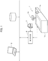
- FIG. 1 is a schematic diagram showing a laser processing system in which a laser processing method is embodied according to the present invention.
- the laser processing system includes a laser processor 1, a CAM 3 serving as an automatic programming system to create a processing program for the laser processor 1, and an NC device 5 to drive the laser processor 1 according to the processing program from the CAM 3.
- the NC device 5 is provided with a fingertip operable wireless mouse 7 to input an instruction from a worker.
- the wireless mouse 7 and NC device 5 form the correction means.
- the laser processor 1 is divided into, as shown in Fig. 1 , a processing side 1a and a preparation side 1b.
- the processing side 1a has a skid-like processing pallet 1a1 on which a material W is placed.
- the material W on the processing pallet 1a1 is laser-processed with a freely movable laser head 1c.
- the preparation side 1b has a skid-like table 1b1 on which a material W is placed.
- a projector 1e is arranged on the processing side 1a in the vicinity of the preparation side 1b.
- Figure 2 is a schematic view showing the processing side 1a of the laser processor 1 shown in Fig. 1 .
- Figure 3 is a functional block diagram showing the NC device 5 shown in Fig. 1 .
- the NC device 5 includes a projection image generating part 5a to generate, according to various information pieces to be explained later, an image to be projected on the material W, a projector driving signal generating part 5b to generate a projector driving signal, a projection image correcting part 5c to move and correct a projection image according to a correction instruction from the worker, a processing program preparing part 5d to prepare a processing program based on the projection image, and a processor driving part 5e to drive the laser processor 1 according to the processing program.
- a projection image generating part 5a to generate, according to various information pieces to be explained later, an image to be projected on the material W
- a projector driving signal generating part 5b to generate a projector driving signal
- a projection image correcting part 5c to move and correct a projection image according to a correction instruction from the worker
- a processing program preparing part 5d to prepare a processing program based on the projection image
- a processor driving part 5e to drive the laser processor 1 according to the processing program.
- the projection image correcting part 5c corrects a position of the projection image according to a projection image correction instruction provided through the fingertip operable wireless mouse 7 used to input a worker's instruction.
- the projection image generating part 5a, projector driving signal generating part 5b, projection image correcting part 5c, processing program preparing part 5d, and processor driving part 5e are constituted by exclusive hardware having the respective functions. Instead, the above-mentioned functions may be realized by software run by a CPU having a RAM and ROM.
- the projector 1e is configured to project an image of a product to process selectively on the material W on the processing pallet 1a1 of the processing side 1a or on the material W on the table 1b1 of the preparation side 1b. Namely, the projector 1e is configured to project an image of a part to process selectively on the materials placed at different locations.
- the projector 1e includes a support post 1e1 fixed to a top face of the processing side 1a in the vicinity of the preparation side 1b, a projecting part 1e3 arranged on the support post 1e1 and freely rotatable by 180 degrees, and a rotational driving part 1e5 to rotate the projecting part 1e3 by 180 degrees around the support post 1e1.
- the rotational driving part 1e5 drives the projecting part 1e3 to selectively orient the projecting part 1e3 to a first position A (indicated with a continuous line) to project an image on the material W on the processing pallet 1a1 of the processing side 1a or to a second position B (indicated with a dot-and-dash line) to project an image on the material W on the table 1b1 of the preparation side 1b.
- the rotational driving part 1e5 includes a motor or the like to rotationally drive the projecting part 1e3 according to a projector driving signal from the NC device 5.
- Figure 4 is a schematic diagram showing the projector 1e shown in Fig. 1 .
- the projector 1e is configured to project, at a given angle, an image C of a part to process selectively on the material Won the processing pallet 1a1 of the processing side 1a or on the material W on the table 1b1 of the preparation side 1b.
- any other configuration is employable.
- the projector may project the image C of the product to process from just above one of the material W on the processing pallet 1a1 of the processing side 1a and the material W on the table 1b1 of the preparation side 1b.
- the projector is moved and set to project the image C of the part to process from just above both the material W on the processing pallet 1a1 of the processing side 1a and the material W on the table 1b1 of the preparation side 1b.
- the projector 1e is configured, as shown in Fig. 5 , to project by projection mapping the image C of the part to process onto a given position of the material W on the processing pallet 1a1 of the processing side 1a or of the material W on the table 1b1 of the preparation side 1b.
- the material W is a remainder having a hole D1 from which a part D has been cut out and a hole E1 from which a part E has been cut out.
- Figure 5 shows a situation to project the image C of the part on the material W on the processing pallet 1a1 of the processing side 1a.
- Figure 5 is an explanatory diagram showing the situation that the projector 1e projects the image C of the part to process on the material W.
- the projector 1e and NC device 5 form the projection means.
- FIG. 6 is a flowchart showing the laser processing method embodied according to the present invention.
- step 101 a processing program generated by the CAM 3 for laser processing to achieve is inputted into the NC device 5.
- the processing program contains product data and the like including processing range information.
- step 103 a worker inputs data about the material W, which is a remainder, into the NC device 5.
- the material data contains shape and thickness data and the like of the material W.
- step 105 the worker inputs into the NC device 5 information about which of the material W on the processing pallet 1a1 of the processing side 1a and the material W on the table 1b1 of the preparation side 1b must be an object to process and positional information about an object material placing skid of the processing pallet 1a1 or of the table 1b1.
- step 107 the worker inputs into the NC device 5 position correction values that are relational parameters of the projected image from the projector 1e, a processing range, and a laser origin.
- step 109 the NC device 5 generates, according to the inputted processing program, material data, and position correction values, a product projection image signal and projector driving signal for the projector 1e.
- a projection height is calculated from the thickness data of the material W, and based on the position correction values and the projection angle information of the projector 1e, a magnification is calculated, adjusted, and set to reduce or enlarge the projection image so that the projection image is displayed at a proper projection location on the material. Then, the projection image signal is generated for the projector 1e.
- the projection image signal for the projector 1e is generated according to boundary information of the product to be drawn with the set magnitude parameter, boundary information of the processing range, and the position correction values.
- the NC device 5 generates, according to the information about on which of the processing pallet 1a1 of the processing side 1a and the table 1b1 of the preparation side 1b is used to place the material W, the projector driving signal to drive the projector 1e so that the projector 1e is oriented to the first position A to illuminate the material W on the processing pallet 1a1 of the processing side 1a or to the second position B to illuminate the material W on the table 1b1 of the preparation side 1b.
- the projection image signal is generated according to the positional information of the skid of the processing pallet 1a1 or of the table 1b1 so that vertex positions of the skid appear as dots on a projected image.
- the projection image signal is generated according to the processible range information related to a movable range of the laser head 1c so that the processible range appears as a line on the projected image.
- the skid vertex positions each are projected as given-sized circles to take account of a skid deformation caused by melting or spattering by laser.
- this embodiment If the skid vertex positions interfere with the projected product image, this embodiment generates the projection image signal so that the interfering positions of the skid are displayed with a different color. Differing the colors of the skid vertexes and projected product image from each other enables the worker to distinguish the interference. Alternatively, the skid vertexes and product projection image may simply be displayed with different colors.
- the product projection image signal for the projector 1e is generated by the projection image generating part 5a of the NC device 5 and the projector driving signal is generated by the projector driving signal generating part 5b of the NC device 5.
- step 111 the projector 1e projects on the material W, according to the projection image signal generated by the NC device 5, the product image together with the dot image of the skid vertex positions and the processible range, i.e., the movable range of the laser head 1c.
- the rotational driving part 1e5 of the projector 1e rotationally drives the projecting part 1e3 according to the projector driving signal generated by the NC device 5 and the projecting part 1e3 of the projector 1e projects the product image on the material W according to the projection image signal for the projector 1e generated by the NC device 5.
- Figure 7 is a schematic plan view showing an example of the product image projected by projection mapping on the material W.
- the product image H is projected by projection mapping.
- the skid vertex positions are projected as spots I, and if some skid vertex positions and the projected product image interfere with each other, the interfering skid vertex positions are displayed with a different color.
- the interfering ones of the skid vertex positions I are depicted with dot lines and the processible range K, i.e., the movable range of the laser head 1c with a dot-and-dash line.
- step 113 the worker inspects the product image H projected on the material W and determines whether or not a position of the projected product image H is proper.
- the worker is able to determine whether or not the product image H is positioned on the part cut-out locations. If the skid vertex positions that are projected on the material W as a dot image interfere with the projected product image, this embodiment displays the interfering skid positions with a different color, and therefore, the worker is able to easily determine the interference between the skid vertex positions and the projected product image.
- the product image H is projected on the material W together with the processible range K, i.e., the movable range of the laser head 1c, and therefore, it is also possible to confirm whether or not the product image H is within the processible range.
- step 115 is achieved.
- step 113 If the above-mentioned step 113 is NO, an instruction is issued in the step 115 to correct the position of the projected product image H.
- the worker uses the fingertip operable wireless mouse 7 to input into the NC device 5 an instruction to move the projected product image H to a proper position.
- the product image H projected by projection mapping on the material W interferes with the projected image of the skid vertex positions I (those indicated with dot lines).
- the wireless mouse 7 is operated to sift the product image H in a lateral direction J by a given distance.
- the product image H is sifted in the lateral direction J by a given distance so that the skid vertex positions I do not interfere with the projected product image.
- Figure 8 is a schematic plan view showing an example of a sifted image of the product projected on the material W by projection mapping.
- the processible range K i.e., the movable range of the laser head 1c is also depicted with a dot-and-dash line.
- This embodiment has explained the case of moving a projected product image so that the projected product image may not interfere with the skid vertex positions I. It is also possible that the worker visually inspects the material W for flaws or spatters that are not known from the data and moves the product image to avoid such flaws or spatters, so that the flaws or spatters are not left on the product.
- Figure 9 is a schematic view showing the fingertip operable wireless mouse 7.
- the wireless mouse 7 is configured to be worn on a finger of a worker and used by the worker and is provided with various buttons. Namely, it has a shift button to sift the projected product image H in a lateral/longitudinal direction, a button to rotate the projected product image H, and the like.
- the means to input a worker's instruction into the NC device 5 is not limited to such a wireless mouse but any other configuration is allowed.
- the above-mentioned step 109 is resumed in which the NC device 5 generates, based on the instruction made in the above-mentioned step 115, i.e., the instruction to sift the projected product image H in the lateral/longitudinal direction or the instruction to rotationally move the projected product image H, a corrected product projection image signal for the projector 1e.
- the generation of the corrected product projection image signal for the projector 1e is made by the projection image correcting part 5c of the NC device 5.
- the projector 1e projects the product image together with the dot image of the skid vertex positions on the material W.
- the product image H is projected on the material W as shown in Fig. 8 with the product image H being sifted in the lateral direction J by a given distance so that the projected product image does not interfere with the skid vertex positions I.
- step 113 the worker inspects the product image H projected on the material W and determines whether or not the position of the projected product image H is proper. If YES (the position of the projected image with respect to the material W is finalized), step 117 is carried out in which the NC device 5 generates and prepares, as processing data, a processing program for the projected product image H.
- the original processing program when no correction has been made on the product projection image for the projector 1e, the original processing program is adopted, and when the product projection image for the projector 1e has been corrected, the original processing program is modified according to the corrected product projection image and the modified processing program is prepared.
- the product image H has been sifted in the lateral direction J by a given distance as shown in Fig. 8 so that the product projection image does not interfere with the skid vertex positions I.
- the positional information is recalculated for the translation, and according to the recalculated positional coordinates, the processing program is prepared.
- the processing program is prepared by the processing program preparing part 5d of the NC device 5.
- step 119 the laser processor is driven according to the processing program prepared in the above-mentioned step 117.
- the processor driving part 5e of the NC device 5 drives the laser processor.
- the projector 1e directly projects on a material W an image of a product to process, and therefore, even if a remainder is used as the material W, a worker is able to easily and surely determine whether or not the position of the image of a part to process is proper.
- a laser processing trace overlaps vertexes of a skid to support a material like the above-mentioned embodiment, it is easy to determine the overlapping of the laser processing trace with the material supporting skid vertexes and correct a processing program so that the laser processing trace does not overlap the material supporting skid vertexes.
- the device to input worker's instructions into the NC device 5, such as an instruction to sift a projected product image in a lateral/longitudinal direction or an instruction to rotationally move the projected product image is not limited to the fingertip operable wireless mouse. It may be, for example, an NC operating screen, a tablet, a pulse generator, or the like.
- the embodiment projects a product image on one piece of material
Landscapes
- Physics & Mathematics (AREA)
- Engineering & Computer Science (AREA)
- Geometry (AREA)
- Human Computer Interaction (AREA)
- Manufacturing & Machinery (AREA)
- General Physics & Mathematics (AREA)
- Automation & Control Theory (AREA)
- Laser Beam Processing (AREA)
- Numerical Control (AREA)
Abstract
Description
- The present invention relates to a laser processing system and a laser processing method that lay out a product to process on a plate-like material or a workpiece and conduct laser processing on the material, and particularly, to a laser processing system and a laser processing method capable of efficiently laying out a product to process on a workpiece such as a remainder material.
- In laser processing by a laser processing system, when the number of products in a lot to process is small or when there is only one piece of product to process, a worker may search a remainder yard for a remainder of proper size and use the remainder for laser processing.
- The remainder occurs after forming a product from a material by, for example, blanking.
- When using such a remainder for laser processing, the worker places the remainder on a pallet of a laser processor, checks a spot such as an LED marker emitted from a laser head to a laser focal position, positions a processing part so that a product to process may come within a processible range of the remainder, feeds back the positional information to a processing program, and carries out laser processing according to the processing program.
-
- Patent Literature 1: Japanese Unexamined Patent Application Publication No.
2000-163111 - Patent Literature 2 : Japanese Unexamined Patent Application Publication No.
2014-48044 - However, the above-mentioned work of positioning a processing part by a worker in the laser processing that uses a workpiece such as a remainder involves a problem of requiring skill and is difficult for an inexperienced worker.
- Namely, when a product to process has a complicated shape or when the product must be rotated and positioned on a remainder which has already been holed, it is hard and requires skill for a worker to position the product on the remainder without interfering with the holes.
- In more detail, the worker must first grasp the size of a rectangle of the product, put a tape rule on the remainder, and confirm whether or not the product interferes with the holes of the remainder. These steps take time. In addition, if the holes of the remainder are complicated and if the product to process has a complicated shape, it is difficult to determine whether or not the product is processible without interfering with the holes of the remainder.
- Also, if a processible area of the remainder is away from a position where the worker stands, it will be difficult for the worker to put the tape rule on the remainder, and when actually carrying out the laser processing, a processed part may overlap the holes of the remainder to cause a problem of producing an unacceptable product.
- Since the program is manually prepared, the laser processing may come out of the processible area of the remainder in the middle of the laser processing. In such a case, problems will occur that the remainder must be discarded by halting the laser processing in the middle and that the laser processing must be again carried out.
- Further, there is a big problem that occurs when a laser processing trace overlaps vertexes of a skid supporting the remainder. If this happens, the remainder and skid are welded together and the vertexes of the skid melt to cause process defects.
- In consideration of the above-mentioned circumstances, an object of the present invention is to provide a laser processing system and a laser processing method capable of, even when employing a remainder for laser-processing a product, efficiently laying out the product on the remainder without skill and without causing process defects.
- In order to solve the problems mentioned above, a feature of the present invention is a laser processing system for irradiating a material with a laser beam and laser-processing the material, comprising: a projection means to project on the material an image of a product to process; and a correction means to move and correct the image projected by the projection means, wherein after determining a position of the projected image with respect to the material, processing data is generated.
- Another feature of the present invention is that the projection means projects, together with the image of the product to process, an image of vertex positions of a processing pallet skid on which the material is placed.
- Another feature of the present invention is that the correction means sifts or rotates the image projected by the projection means.
- Another feature of the present invention is that, according to the projected image moved and corrected by the correction means, the processing data is corrected.
- Another feature of the present invention is that the material is a remainder that occurs after processing a product, and on the remainder, the image of the product to process is projected to determine whether or not a processing position of the product to process is appropriate.
- Another feature of the present invention is that the projection means projects the image of the product to process selectively on materials placed at different locations.
- Another feature of the present invention is a laser processing method in a laser processing system for irradiating a material with a laser beam and laser-processing the material, comprising: projecting, by a projection means, an image of a product to process on the material; determining whether or not a processing position of the product to process is appropriate; and if the processing position of the product to process is inappropriate, moving and correcting, by a correction means, the projected image on the material, wherein after determining a position of the projected image with respect to the material, and processing data is generated.
-
- [
Fig. 1] Fig. 1 is a schematic diagram showing a laser processing system in which a laser processing method is embodied according to the present invention. - [
Fig. 2] Fig. 2 is a schematic diagram showing aprocessing side 1a of a laser processor 1 shown inFig. 1 . - [
Fig. 3] Fig. 3 is a functional block diagram showing anNC device 5 shown inFig. 1 . - [
Fig. 4] Fig. 4 is a schematic diagram showing aprojector 1e shown inFig. 1 . - [
Fig. 5] Fig. 5 is an explanatory diagram showing a state that theprojector 1e shown inFig. 1 projects on a material W an image of a product to process. - [
Fig. 6] Fig. 6 is a flowchart showing a laser processing method embodied according to the present invention. - [
Fig. 7] Fig. 7 is a schematic plan view showing an example of an image of a product projected by projection mapping on a material W. - [
Fig. 8] Fig. 8 is a schematic plan view showing an example of a sifted image of the product projected by projection mapping on the material W. - [
Fig. 9] Fig. 9 is a schematic diagram showing a fingertip operablewireless mouse 7. - Hereinafter, embodiments according to the present invention will be explained with reference to the drawings.
-
Figure 1 is a schematic diagram showing a laser processing system in which a laser processing method is embodied according to the present invention. - As shown in
Fig. 1 , the laser processing system includes a laser processor 1, aCAM 3 serving as an automatic programming system to create a processing program for the laser processor 1, and anNC device 5 to drive the laser processor 1 according to the processing program from theCAM 3. - The
NC device 5 is provided with a fingertip operablewireless mouse 7 to input an instruction from a worker. - The
wireless mouse 7 andNC device 5 form the correction means. - The laser processor 1 is divided into, as shown in
Fig. 1 , aprocessing side 1a and apreparation side 1b. As shown inFig. 2 , theprocessing side 1a has a skid-like processing pallet 1a1 on which a material W is placed. The material W on the processing pallet 1a1 is laser-processed with a freelymovable laser head 1c. Also, thepreparation side 1b has a skid-like table 1b1 on which a material W is placed. - On the
processing side 1a in the vicinity of thepreparation side 1b, aprojector 1e is arranged. -
Figure 2 is a schematic view showing theprocessing side 1a of the laser processor 1 shown inFig. 1 . -
Figure 3 is a functional block diagram showing theNC device 5 shown inFig. 1 . - As shown in
Fig. 3 , theNC device 5 includes a projectionimage generating part 5a to generate, according to various information pieces to be explained later, an image to be projected on the material W, a projector drivingsignal generating part 5b to generate a projector driving signal, a projectionimage correcting part 5c to move and correct a projection image according to a correction instruction from the worker, a processingprogram preparing part 5d to prepare a processing program based on the projection image, and aprocessor driving part 5e to drive the laser processor 1 according to the processing program. - The projection
image correcting part 5c corrects a position of the projection image according to a projection image correction instruction provided through the fingertip operablewireless mouse 7 used to input a worker's instruction. - In
Fig. 3 , the projectionimage generating part 5a, projector drivingsignal generating part 5b, projectionimage correcting part 5c, processingprogram preparing part 5d, andprocessor driving part 5e are constituted by exclusive hardware having the respective functions. Instead, the above-mentioned functions may be realized by software run by a CPU having a RAM and ROM. - The
projector 1e is configured to project an image of a product to process selectively on the material W on the processing pallet 1a1 of theprocessing side 1a or on the material W on the table 1b1 of thepreparation side 1b. Namely, theprojector 1e is configured to project an image of a part to process selectively on the materials placed at different locations. - As shown in
Fig. 4 , theprojector 1e includes a support post 1e1 fixed to a top face of theprocessing side 1a in the vicinity of thepreparation side 1b, a projecting part 1e3 arranged on the support post 1e1 and freely rotatable by 180 degrees, and a rotational driving part 1e5 to rotate the projecting part 1e3 by 180 degrees around the support post 1e1. The rotational driving part 1e5 drives the projecting part 1e3 to selectively orient the projecting part 1e3 to a first position A (indicated with a continuous line) to project an image on the material W on the processing pallet 1a1 of theprocessing side 1a or to a second position B (indicated with a dot-and-dash line) to project an image on the material W on the table 1b1 of thepreparation side 1b. The rotational driving part 1e5 includes a motor or the like to rotationally drive the projecting part 1e3 according to a projector driving signal from theNC device 5. -
Figure 4 is a schematic diagram showing theprojector 1e shown inFig. 1 . - As shown in
Fig. 4 , theprojector 1e according to this embodiment is configured to project, at a given angle, an image C of a part to process selectively on the material Won the processing pallet 1a1 of theprocessing side 1a or on the material W on the table 1b1 of thepreparation side 1b. Instead, any other configuration is employable. - Namely, it is possible to configure so that the projector may project the image C of the product to process from just above one of the material W on the processing pallet 1a1 of the
processing side 1a and the material W on the table 1b1 of thepreparation side 1b. Alternatively, it is possible to configure so that the projector is moved and set to project the image C of the part to process from just above both the material W on the processing pallet 1a1 of theprocessing side 1a and the material W on the table 1b1 of thepreparation side 1b. - The
projector 1e is configured, as shown inFig. 5 , to project by projection mapping the image C of the part to process onto a given position of the material W on the processing pallet 1a1 of theprocessing side 1a or of the material W on the table 1b1 of thepreparation side 1b. InFig. 5 , the material W is a remainder having a hole D1 from which a part D has been cut out and a hole E1 from which a part E has been cut out.Figure 5 shows a situation to project the image C of the part on the material W on the processing pallet 1a1 of theprocessing side 1a. -
Figure 5 is an explanatory diagram showing the situation that theprojector 1e projects the image C of the part to process on the material W. - The
projector 1e andNC device 5 form the projection means. - Next, with reference to
Fig. 6 , the laser processing method embodied according to the present invention will be explained. -
Figure 6 is a flowchart showing the laser processing method embodied according to the present invention. - First, in
step 101, a processing program generated by theCAM 3 for laser processing to achieve is inputted into theNC device 5. Here, the processing program contains product data and the like including processing range information. - In
step 103, a worker inputs data about the material W, which is a remainder, into theNC device 5. Here, the material data contains shape and thickness data and the like of the material W. - Together with this, in
step 105, the worker inputs into theNC device 5 information about which of the material W on the processing pallet 1a1 of theprocessing side 1a and the material W on the table 1b1 of thepreparation side 1b must be an object to process and positional information about an object material placing skid of the processing pallet 1a1 or of the table 1b1. - Next, in
step 107, the worker inputs into theNC device 5 position correction values that are relational parameters of the projected image from theprojector 1e, a processing range, and a laser origin. - In
step 109, theNC device 5 generates, according to the inputted processing program, material data, and position correction values, a product projection image signal and projector driving signal for theprojector 1e. - Here, for the processing program, a projection height is calculated from the thickness data of the material W, and based on the position correction values and the projection angle information of the
projector 1e, a magnification is calculated, adjusted, and set to reduce or enlarge the projection image so that the projection image is displayed at a proper projection location on the material. Then, the projection image signal is generated for theprojector 1e. - Namely, the projection image signal for the
projector 1e is generated according to boundary information of the product to be drawn with the set magnitude parameter, boundary information of the processing range, and the position correction values. - Also, the
NC device 5 generates, according to the information about on which of the processing pallet 1a1 of theprocessing side 1a and the table 1b1 of thepreparation side 1b is used to place the material W, the projector driving signal to drive theprojector 1e so that theprojector 1e is oriented to the first position A to illuminate the material W on the processing pallet 1a1 of theprocessing side 1a or to the second position B to illuminate the material W on the table 1b1 of thepreparation side 1b. - Also, the projection image signal is generated according to the positional information of the skid of the processing pallet 1a1 or of the table 1b1 so that vertex positions of the skid appear as dots on a projected image. In addition, the projection image signal is generated according to the processible range information related to a movable range of the
laser head 1c so that the processible range appears as a line on the projected image. - Here, the skid vertex positions each are projected as given-sized circles to take account of a skid deformation caused by melting or spattering by laser.
- If the skid vertex positions interfere with the projected product image, this embodiment generates the projection image signal so that the interfering positions of the skid are displayed with a different color. Differing the colors of the skid vertexes and projected product image from each other enables the worker to distinguish the interference. Alternatively, the skid vertexes and product projection image may simply be displayed with different colors.
- It is also possible to project the processible range, i.e., the movable range of the
laser head 1c with a different color. - The product projection image signal for the
projector 1e is generated by the projectionimage generating part 5a of theNC device 5 and the projector driving signal is generated by the projector drivingsignal generating part 5b of theNC device 5. - Next, in
step 111, theprojector 1e projects on the material W, according to the projection image signal generated by theNC device 5, the product image together with the dot image of the skid vertex positions and the processible range, i.e., the movable range of thelaser head 1c. - Namely, at first, the rotational driving part 1e5 of the
projector 1e rotationally drives the projecting part 1e3 according to the projector driving signal generated by theNC device 5 and the projecting part 1e3 of theprojector 1e projects the product image on the material W according to the projection image signal for theprojector 1e generated by theNC device 5. -
Figure 7 is a schematic plan view showing an example of the product image projected by projection mapping on the material W. - As shown in
Fig. 7 , on the material W that is a remainder having a hole F1 from which a part F has already been cut out and a hole G1 from which a part G has already been cut out, the product image H is projected by projection mapping. In addition, the skid vertex positions are projected as spots I, and if some skid vertex positions and the projected product image interfere with each other, the interfering skid vertex positions are displayed with a different color. InFig. 7 , the interfering ones of the skid vertex positions I are depicted with dot lines and the processible range K, i.e., the movable range of thelaser head 1c with a dot-and-dash line. - Next, in
step 113, the worker inspects the product image H projected on the material W and determines whether or not a position of the projected product image H is proper. - Namely, the worker is able to determine whether or not the product image H is positioned on the part cut-out locations. If the skid vertex positions that are projected on the material W as a dot image interfere with the projected product image, this embodiment displays the interfering skid positions with a different color, and therefore, the worker is able to easily determine the interference between the skid vertex positions and the projected product image.
- Further, the product image H is projected on the material W together with the processible range K, i.e., the movable range of the
laser head 1c, and therefore, it is also possible to confirm whether or not the product image H is within the processible range. - If the skid vertex positions and projected product image interfere with each other or if the projected product image is on the part cut-out locations, i.e., if the position of the projected product image H is improper (NO in step 113),
step 115 is achieved. - If the above-mentioned
step 113 is NO, an instruction is issued in thestep 115 to correct the position of the projected product image H. - Here, the worker uses the fingertip
operable wireless mouse 7 to input into theNC device 5 an instruction to move the projected product image H to a proper position. - Namely, to move the product image H projected by projection mapping on the material W, an instruction to sift the projected product image H in a lateral/longitudinal direction or an instruction to rotationally move the projected product image H is inputted through the
wireless mouse 7. - For example, as shown in the schematic plan view of
Fig. 7 , the product image H projected by projection mapping on the material W interferes with the projected image of the skid vertex positions I (those indicated with dot lines). In this case, thewireless mouse 7 is operated to sift the product image H in a lateral direction J by a given distance. Namely, as shown inFig. 8 , the product image H is sifted in the lateral direction J by a given distance so that the skid vertex positions I do not interfere with the projected product image. At this movement, it is possible to confirm whether or not the product image H is moved within the processible range K. - When translating the product image H in the lateral direction J by a given distance, it is possible to change the color of the product image H.
- Further, to move the product image H, it is possible to predetermine a moving pitch so that the product image H is moved by the moving pitch whenever a predetermined button of the
wireless mouse 7 is clicked once. -
Figure 8 is a schematic plan view showing an example of a sifted image of the product projected on the material W by projection mapping. InFig. 8 , the processible range K, i.e., the movable range of thelaser head 1c is also depicted with a dot-and-dash line. - This embodiment has explained the case of moving a projected product image so that the projected product image may not interfere with the skid vertex positions I. It is also possible that the worker visually inspects the material W for flaws or spatters that are not known from the data and moves the product image to avoid such flaws or spatters, so that the flaws or spatters are not left on the product.
-
Figure 9 is a schematic view showing the fingertipoperable wireless mouse 7. - As shown in
Fig. 9 , according to this embodiment, thewireless mouse 7 is configured to be worn on a finger of a worker and used by the worker and is provided with various buttons. Namely, it has a shift button to sift the projected product image H in a lateral/longitudinal direction, a button to rotate the projected product image H, and the like. The means to input a worker's instruction into theNC device 5 is not limited to such a wireless mouse but any other configuration is allowed. - Once the instruction to correct the position of the projected product image H is made, the above-mentioned
step 109 is resumed in which theNC device 5 generates, based on the instruction made in the above-mentionedstep 115, i.e., the instruction to sift the projected product image H in the lateral/longitudinal direction or the instruction to rotationally move the projected product image H, a corrected product projection image signal for theprojector 1e. - Here, the generation of the corrected product projection image signal for the
projector 1e is made by the projectionimage correcting part 5c of theNC device 5. - Next, in the above-mentioned
step 111, based on the corrected projection image signal generated by theNC device 5, theprojector 1e projects the product image together with the dot image of the skid vertex positions on the material W. - Accordingly, in the above-mentioned example, the product image H is projected on the material W as shown in
Fig. 8 with the product image H being sifted in the lateral direction J by a given distance so that the projected product image does not interfere with the skid vertex positions I. - Next, in the above-mentioned
step 113, the worker inspects the product image H projected on the material W and determines whether or not the position of the projected product image H is proper. If YES (the position of the projected image with respect to the material W is finalized),step 117 is carried out in which theNC device 5 generates and prepares, as processing data, a processing program for the projected product image H. - Namely, when no correction has been made on the product projection image for the
projector 1e, the original processing program is adopted, and when the product projection image for theprojector 1e has been corrected, the original processing program is modified according to the corrected product projection image and the modified processing program is prepared. - In the above-mentioned example, the product image H has been sifted in the lateral direction J by a given distance as shown in
Fig. 8 so that the product projection image does not interfere with the skid vertex positions I. In this case, the positional information is recalculated for the translation, and according to the recalculated positional coordinates, the processing program is prepared. - Here, the processing program is prepared by the processing
program preparing part 5d of theNC device 5. - Next, in
step 119, the laser processor is driven according to the processing program prepared in the above-mentionedstep 117. Here, theprocessor driving part 5e of theNC device 5 drives the laser processor. - In this way, according to this embodiment, the
projector 1e directly projects on a material W an image of a product to process, and therefore, even if a remainder is used as the material W, a worker is able to easily and surely determine whether or not the position of the image of a part to process is proper. - Namely, when using a remainder in which holes have already been made, it is easy to determine whether or not a part to process interferes with the holes and correct a processing program so that the part to process does not interfere with the holes.
- Further, when a laser processing trace overlaps vertexes of a skid to support a material like the above-mentioned embodiment, it is easy to determine the overlapping of the laser processing trace with the material supporting skid vertexes and correct a processing program so that the laser processing trace does not overlap the material supporting skid vertexes.
- The present invention is not limited to the above-mentioned embodiments and is achievable in other forms by making proper modifications on the present invention.
- Namely, the device to input worker's instructions into the
NC device 5, such as an instruction to sift a projected product image in a lateral/longitudinal direction or an instruction to rotationally move the projected product image is not limited to the fingertip operable wireless mouse. It may be, for example, an NC operating screen, a tablet, a pulse generator, or the like. - Further, although the embodiment projects a product image on one piece of material, it is possible to use the present invention to project a product image on each of a plurality of materials.
- According to the present invention, it is possible to efficiently lay out a product on a remainder so that no processing defects occur.
Claims (7)
- A laser processing system for irradiating a material with a laser beam and laser-processing the material, comprising:a projection means to project on the material an image of a product to process; anda correction means to move and correct the image projected by the projection means,wherein after determining a position of the projected image with respect to the material, processing data is generated.
- The laser processing system according to claim 1, wherein the projection means projects, together with the image of the product to process, an image of vertex positions of a processing pallet skid on which the material is placed.
- The laser processing system according to one of claims 1 and 2, wherein the correction means sifts or rotates the image projected by the projection means.
- The laser processing system according to claim 1, wherein according to the projected image moved and corrected by the correction means, the processing data is corrected.
- The laser processing system according to claim 1, wherein the material is a remainder that occurs after processing a product, and on the remainder, the image of the product to process is projected to determine whether or not a processing position of the product to process is appropriate.
- The laser processing system according to claim 1, wherein the projection means projects the image of the product to process selectively on materials placed at different locations.
- A laser processing method in a laser processing system for irradiating a material with a laser beam and laser-processing the material, comprising:projecting, by a projection means, an image of a product to process on the material;determining whether or not a processing position of the product to process is appropriate; andmoving and correcting, by a correction means, the projected image on the material, if the processing position of the product to process is inappropriate,wherein after determining a position of the projected image with respect to the material, and processing data is generated.
Applications Claiming Priority (2)
| Application Number | Priority Date | Filing Date | Title |
|---|---|---|---|
| JP2017074305A JP6463403B2 (en) | 2017-04-04 | 2017-04-04 | Laser processing system |
| PCT/JP2018/013702 WO2018186301A1 (en) | 2017-04-04 | 2018-03-30 | Laser machining system and laser machining method |
Publications (3)
| Publication Number | Publication Date |
|---|---|
| EP3608738A1 true EP3608738A1 (en) | 2020-02-12 |
| EP3608738A4 EP3608738A4 (en) | 2020-04-08 |
| EP3608738B1 EP3608738B1 (en) | 2021-07-28 |
Family
ID=63713484
Family Applications (1)
| Application Number | Title | Priority Date | Filing Date |
|---|---|---|---|
| EP18781542.8A Active EP3608738B1 (en) | 2017-04-04 | 2018-03-30 | Laser machining system and laser machining method |
Country Status (3)
| Country | Link |
|---|---|
| EP (1) | EP3608738B1 (en) |
| JP (1) | JP6463403B2 (en) |
| WO (1) | WO2018186301A1 (en) |
Family Cites Families (19)
| Publication number | Priority date | Publication date | Assignee | Title |
|---|---|---|---|---|
| JPH03106588A (en) * | 1989-09-21 | 1991-05-07 | Komatsu Ltd | Control method for laser beam machine |
| JPH07299682A (en) * | 1994-04-28 | 1995-11-14 | Nippei Toyama Corp | Processing device and processing method |
| DE19522717C1 (en) * | 1995-06-22 | 1996-12-12 | Duerkopp Adler Ag | Process for cutting or punching individual parts from an animal skin |
| JP3623318B2 (en) * | 1996-07-09 | 2005-02-23 | 株式会社アマダ | Laser punch combined processing machine |
| JP2000163111A (en) | 1998-11-26 | 2000-06-16 | Amada Co Ltd | Blanking graphic compiling method, cnc device with graphic compiling function and storage medium storing program of blaking graphic compiling method |
| JP2001273017A (en) * | 2000-03-24 | 2001-10-05 | Daihen Corp | Machining method of laser beam machine |
| EP1157793A1 (en) * | 2000-05-26 | 2001-11-28 | Thea Felber | Apparatus and method for adjusting a marker to the surface of a material |
| JP2003071580A (en) * | 2001-09-04 | 2003-03-11 | Murata Mach Ltd | Plate material nesting cutting line preparation device and method |
| EP1524063A1 (en) * | 2003-10-08 | 2005-04-20 | Trumpf Werkzeugmaschinen GmbH + Co. KG | Marking device and process of controlled collecting for cut or stamped workpieces of a plate |
| JP2005189932A (en) * | 2003-12-24 | 2005-07-14 | Sekisui House Ltd | Plate material allocating device, plate material allocating program, and computer readable recording medium recording plate material allocating program |
| JP4390622B2 (en) * | 2004-05-13 | 2009-12-24 | 株式会社アイ・エイチ・アイ マリンユナイテッド | Automatic nesting method |
| JP5228954B2 (en) * | 2009-02-03 | 2013-07-03 | 村田機械株式会社 | Nesting equipment and plate processing equipment |
| JP2011018205A (en) * | 2009-07-09 | 2011-01-27 | Amada Co Ltd | Nesting data generation device and nesting data generation method |
| JP2012243045A (en) * | 2011-05-19 | 2012-12-10 | Murata Mach Ltd | Sheet metal process operation support system |
| JP2014048044A (en) | 2012-08-29 | 2014-03-17 | Amada Co Ltd | Material recognition system and its method |
| JP6019986B2 (en) * | 2012-09-19 | 2016-11-02 | 村田機械株式会社 | Board processing system |
| US9789462B2 (en) * | 2013-06-25 | 2017-10-17 | The Boeing Company | Apparatuses and methods for accurate structure marking and marking-assisted structure locating |
| JP6287293B2 (en) * | 2014-02-07 | 2018-03-07 | セイコーエプソン株式会社 | Display system, display device, and display method |
| WO2015159547A1 (en) * | 2014-04-18 | 2015-10-22 | 日本電気株式会社 | Information processing system, control method, and program recording medium |
-
2017
- 2017-04-04 JP JP2017074305A patent/JP6463403B2/en active Active
-
2018
- 2018-03-30 EP EP18781542.8A patent/EP3608738B1/en active Active
- 2018-03-30 WO PCT/JP2018/013702 patent/WO2018186301A1/en not_active Ceased
Also Published As
| Publication number | Publication date |
|---|---|
| EP3608738A4 (en) | 2020-04-08 |
| EP3608738B1 (en) | 2021-07-28 |
| JP2018180616A (en) | 2018-11-15 |
| WO2018186301A1 (en) | 2018-10-11 |
| JP6463403B2 (en) | 2019-01-30 |
Similar Documents
| Publication | Publication Date | Title |
|---|---|---|
| US8706300B2 (en) | Method of controlling a robotic tool | |
| JP5645687B2 (en) | Laser processing apparatus and laser processing method | |
| JP4353219B2 (en) | Laser processing apparatus and control method of laser processing apparatus | |
| JP5154616B2 (en) | Offline teaching method | |
| CN112620926B (en) | Welding spot tracking method and device and storage medium | |
| JP3071758B2 (en) | Three-dimensional laser beam machine and processing control method for processing program in three-dimensional laser beam machine | |
| KR20150117592A (en) | Teaching system, robot system, and teaching method | |
| JP2012135781A (en) | Method and device for teaching laser machining robot | |
| JP2002036177A (en) | Apparatus and method for cutting a combination of sheet members | |
| JP2020006378A (en) | Method of generating database for weld design assistance, weld design assistance method and program | |
| JP4836458B2 (en) | How to create an operation program | |
| KR101563722B1 (en) | Ar based i/o device for machine center | |
| JP5909355B2 (en) | Automatic programming apparatus and method for laser processing machine and laser processing system | |
| JP7289087B2 (en) | Repair welding equipment and repair welding method | |
| CN108928132A (en) | Laser mark figure divides arranging system | |
| EP3608738B1 (en) | Laser machining system and laser machining method | |
| JPH09271977A (en) | Machining control program creation device | |
| JP2000339011A (en) | Three-dimensional linear processing machine and method of controlling creation of processing program in three-dimensional linear processing machine | |
| US20240123537A1 (en) | Offline teaching device and offline teaching method | |
| CN115210036A (en) | Weld bead appearance inspection device, weld bead appearance inspection method, program, and weld bead appearance inspection system | |
| JP4280338B2 (en) | Teaching method and apparatus for YAG laser processing machine | |
| JP2015150655A (en) | Method for teaching laser machining pattern and method for operating robot | |
| JP3203507B2 (en) | Laser processing equipment | |
| TWI803593B (en) | Continuous marking laser marking system | |
| TWM583788U (en) | Laser marking system for continuous bounded marking |
Legal Events
| Date | Code | Title | Description |
|---|---|---|---|
| STAA | Information on the status of an ep patent application or granted ep patent |
Free format text: STATUS: THE INTERNATIONAL PUBLICATION HAS BEEN MADE |
|
| PUAI | Public reference made under article 153(3) epc to a published international application that has entered the european phase |
Free format text: ORIGINAL CODE: 0009012 |
|
| STAA | Information on the status of an ep patent application or granted ep patent |
Free format text: STATUS: REQUEST FOR EXAMINATION WAS MADE |
|
| 17P | Request for examination filed |
Effective date: 20191104 |
|
| AK | Designated contracting states |
Kind code of ref document: A1 Designated state(s): AL AT BE BG CH CY CZ DE DK EE ES FI FR GB GR HR HU IE IS IT LI LT LU LV MC MK MT NL NO PL PT RO RS SE SI SK SM TR |
|
| AX | Request for extension of the european patent |
Extension state: BA ME |
|
| A4 | Supplementary search report drawn up and despatched |
Effective date: 20200306 |
|
| RIC1 | Information provided on ipc code assigned before grant |
Ipc: G05B 19/4093 20060101AFI20200302BHEP |
|
| DAV | Request for validation of the european patent (deleted) | ||
| DAX | Request for extension of the european patent (deleted) | ||
| STAA | Information on the status of an ep patent application or granted ep patent |
Free format text: STATUS: EXAMINATION IS IN PROGRESS |
|
| 17Q | First examination report despatched |
Effective date: 20201020 |
|
| GRAP | Despatch of communication of intention to grant a patent |
Free format text: ORIGINAL CODE: EPIDOSNIGR1 |
|
| STAA | Information on the status of an ep patent application or granted ep patent |
Free format text: STATUS: GRANT OF PATENT IS INTENDED |
|
| INTG | Intention to grant announced |
Effective date: 20210324 |
|
| GRAS | Grant fee paid |
Free format text: ORIGINAL CODE: EPIDOSNIGR3 |
|
| GRAA | (expected) grant |
Free format text: ORIGINAL CODE: 0009210 |
|
| STAA | Information on the status of an ep patent application or granted ep patent |
Free format text: STATUS: THE PATENT HAS BEEN GRANTED |
|
| AK | Designated contracting states |
Kind code of ref document: B1 Designated state(s): AL AT BE BG CH CY CZ DE DK EE ES FI FR GB GR HR HU IE IS IT LI LT LU LV MC MK MT NL NO PL PT RO RS SE SI SK SM TR |
|
| REG | Reference to a national code |
Ref country code: GB Ref legal event code: FG4D |
|
| REG | Reference to a national code |
Ref country code: CH Ref legal event code: EP |
|
| REG | Reference to a national code |
Ref country code: AT Ref legal event code: REF Ref document number: 1415261 Country of ref document: AT Kind code of ref document: T Effective date: 20210815 |
|
| REG | Reference to a national code |
Ref country code: IE Ref legal event code: FG4D |
|
| REG | Reference to a national code |
Ref country code: DE Ref legal event code: R096 Ref document number: 602018020923 Country of ref document: DE |
|
| REG | Reference to a national code |
Ref country code: LT Ref legal event code: MG9D |
|
| REG | Reference to a national code |
Ref country code: NL Ref legal event code: MP Effective date: 20210728 |
|
| REG | Reference to a national code |
Ref country code: AT Ref legal event code: MK05 Ref document number: 1415261 Country of ref document: AT Kind code of ref document: T Effective date: 20210728 |
|
| PG25 | Lapsed in a contracting state [announced via postgrant information from national office to epo] |
Ref country code: SE Free format text: LAPSE BECAUSE OF FAILURE TO SUBMIT A TRANSLATION OF THE DESCRIPTION OR TO PAY THE FEE WITHIN THE PRESCRIBED TIME-LIMIT Effective date: 20210728 Ref country code: RS Free format text: LAPSE BECAUSE OF FAILURE TO SUBMIT A TRANSLATION OF THE DESCRIPTION OR TO PAY THE FEE WITHIN THE PRESCRIBED TIME-LIMIT Effective date: 20210728 Ref country code: HR Free format text: LAPSE BECAUSE OF FAILURE TO SUBMIT A TRANSLATION OF THE DESCRIPTION OR TO PAY THE FEE WITHIN THE PRESCRIBED TIME-LIMIT Effective date: 20210728 Ref country code: ES Free format text: LAPSE BECAUSE OF FAILURE TO SUBMIT A TRANSLATION OF THE DESCRIPTION OR TO PAY THE FEE WITHIN THE PRESCRIBED TIME-LIMIT Effective date: 20210728 Ref country code: FI Free format text: LAPSE BECAUSE OF FAILURE TO SUBMIT A TRANSLATION OF THE DESCRIPTION OR TO PAY THE FEE WITHIN THE PRESCRIBED TIME-LIMIT Effective date: 20210728 Ref country code: NL Free format text: LAPSE BECAUSE OF FAILURE TO SUBMIT A TRANSLATION OF THE DESCRIPTION OR TO PAY THE FEE WITHIN THE PRESCRIBED TIME-LIMIT Effective date: 20210728 Ref country code: NO Free format text: LAPSE BECAUSE OF FAILURE TO SUBMIT A TRANSLATION OF THE DESCRIPTION OR TO PAY THE FEE WITHIN THE PRESCRIBED TIME-LIMIT Effective date: 20211028 Ref country code: PT Free format text: LAPSE BECAUSE OF FAILURE TO SUBMIT A TRANSLATION OF THE DESCRIPTION OR TO PAY THE FEE WITHIN THE PRESCRIBED TIME-LIMIT Effective date: 20211129 Ref country code: LT Free format text: LAPSE BECAUSE OF FAILURE TO SUBMIT A TRANSLATION OF THE DESCRIPTION OR TO PAY THE FEE WITHIN THE PRESCRIBED TIME-LIMIT Effective date: 20210728 Ref country code: BG Free format text: LAPSE BECAUSE OF FAILURE TO SUBMIT A TRANSLATION OF THE DESCRIPTION OR TO PAY THE FEE WITHIN THE PRESCRIBED TIME-LIMIT Effective date: 20211028 Ref country code: AT Free format text: LAPSE BECAUSE OF FAILURE TO SUBMIT A TRANSLATION OF THE DESCRIPTION OR TO PAY THE FEE WITHIN THE PRESCRIBED TIME-LIMIT Effective date: 20210728 |
|
| PG25 | Lapsed in a contracting state [announced via postgrant information from national office to epo] |
Ref country code: PL Free format text: LAPSE BECAUSE OF FAILURE TO SUBMIT A TRANSLATION OF THE DESCRIPTION OR TO PAY THE FEE WITHIN THE PRESCRIBED TIME-LIMIT Effective date: 20210728 Ref country code: LV Free format text: LAPSE BECAUSE OF FAILURE TO SUBMIT A TRANSLATION OF THE DESCRIPTION OR TO PAY THE FEE WITHIN THE PRESCRIBED TIME-LIMIT Effective date: 20210728 Ref country code: GR Free format text: LAPSE BECAUSE OF FAILURE TO SUBMIT A TRANSLATION OF THE DESCRIPTION OR TO PAY THE FEE WITHIN THE PRESCRIBED TIME-LIMIT Effective date: 20211029 |
|
| PG25 | Lapsed in a contracting state [announced via postgrant information from national office to epo] |
Ref country code: DK Free format text: LAPSE BECAUSE OF FAILURE TO SUBMIT A TRANSLATION OF THE DESCRIPTION OR TO PAY THE FEE WITHIN THE PRESCRIBED TIME-LIMIT Effective date: 20210728 |
|
| REG | Reference to a national code |
Ref country code: DE Ref legal event code: R097 Ref document number: 602018020923 Country of ref document: DE |
|
| PG25 | Lapsed in a contracting state [announced via postgrant information from national office to epo] |
Ref country code: SM Free format text: LAPSE BECAUSE OF FAILURE TO SUBMIT A TRANSLATION OF THE DESCRIPTION OR TO PAY THE FEE WITHIN THE PRESCRIBED TIME-LIMIT Effective date: 20210728 Ref country code: SK Free format text: LAPSE BECAUSE OF FAILURE TO SUBMIT A TRANSLATION OF THE DESCRIPTION OR TO PAY THE FEE WITHIN THE PRESCRIBED TIME-LIMIT Effective date: 20210728 Ref country code: RO Free format text: LAPSE BECAUSE OF FAILURE TO SUBMIT A TRANSLATION OF THE DESCRIPTION OR TO PAY THE FEE WITHIN THE PRESCRIBED TIME-LIMIT Effective date: 20210728 Ref country code: EE Free format text: LAPSE BECAUSE OF FAILURE TO SUBMIT A TRANSLATION OF THE DESCRIPTION OR TO PAY THE FEE WITHIN THE PRESCRIBED TIME-LIMIT Effective date: 20210728 Ref country code: CZ Free format text: LAPSE BECAUSE OF FAILURE TO SUBMIT A TRANSLATION OF THE DESCRIPTION OR TO PAY THE FEE WITHIN THE PRESCRIBED TIME-LIMIT Effective date: 20210728 Ref country code: AL Free format text: LAPSE BECAUSE OF FAILURE TO SUBMIT A TRANSLATION OF THE DESCRIPTION OR TO PAY THE FEE WITHIN THE PRESCRIBED TIME-LIMIT Effective date: 20210728 |
|
| PLBE | No opposition filed within time limit |
Free format text: ORIGINAL CODE: 0009261 |
|
| STAA | Information on the status of an ep patent application or granted ep patent |
Free format text: STATUS: NO OPPOSITION FILED WITHIN TIME LIMIT |
|
| 26N | No opposition filed |
Effective date: 20220429 |
|
| PG25 | Lapsed in a contracting state [announced via postgrant information from national office to epo] |
Ref country code: IT Free format text: LAPSE BECAUSE OF FAILURE TO SUBMIT A TRANSLATION OF THE DESCRIPTION OR TO PAY THE FEE WITHIN THE PRESCRIBED TIME-LIMIT Effective date: 20210728 |
|
| PG25 | Lapsed in a contracting state [announced via postgrant information from national office to epo] |
Ref country code: MC Free format text: LAPSE BECAUSE OF FAILURE TO SUBMIT A TRANSLATION OF THE DESCRIPTION OR TO PAY THE FEE WITHIN THE PRESCRIBED TIME-LIMIT Effective date: 20210728 |
|
| REG | Reference to a national code |
Ref country code: CH Ref legal event code: PL |
|
| GBPC | Gb: european patent ceased through non-payment of renewal fee |
Effective date: 20220330 |
|
| REG | Reference to a national code |
Ref country code: BE Ref legal event code: MM Effective date: 20220331 |
|
| PG25 | Lapsed in a contracting state [announced via postgrant information from national office to epo] |
Ref country code: LU Free format text: LAPSE BECAUSE OF NON-PAYMENT OF DUE FEES Effective date: 20220330 Ref country code: LI Free format text: LAPSE BECAUSE OF NON-PAYMENT OF DUE FEES Effective date: 20220331 Ref country code: IE Free format text: LAPSE BECAUSE OF NON-PAYMENT OF DUE FEES Effective date: 20220330 Ref country code: GB Free format text: LAPSE BECAUSE OF NON-PAYMENT OF DUE FEES Effective date: 20220330 Ref country code: FR Free format text: LAPSE BECAUSE OF NON-PAYMENT OF DUE FEES Effective date: 20220331 Ref country code: CH Free format text: LAPSE BECAUSE OF NON-PAYMENT OF DUE FEES Effective date: 20220331 |
|
| PG25 | Lapsed in a contracting state [announced via postgrant information from national office to epo] |
Ref country code: BE Free format text: LAPSE BECAUSE OF NON-PAYMENT OF DUE FEES Effective date: 20220331 |
|
| P01 | Opt-out of the competence of the unified patent court (upc) registered |
Effective date: 20230428 |
|
| PG25 | Lapsed in a contracting state [announced via postgrant information from national office to epo] |
Ref country code: MK Free format text: LAPSE BECAUSE OF FAILURE TO SUBMIT A TRANSLATION OF THE DESCRIPTION OR TO PAY THE FEE WITHIN THE PRESCRIBED TIME-LIMIT Effective date: 20210728 Ref country code: CY Free format text: LAPSE BECAUSE OF FAILURE TO SUBMIT A TRANSLATION OF THE DESCRIPTION OR TO PAY THE FEE WITHIN THE PRESCRIBED TIME-LIMIT Effective date: 20210728 |
|
| PG25 | Lapsed in a contracting state [announced via postgrant information from national office to epo] |
Ref country code: HU Free format text: LAPSE BECAUSE OF FAILURE TO SUBMIT A TRANSLATION OF THE DESCRIPTION OR TO PAY THE FEE WITHIN THE PRESCRIBED TIME-LIMIT; INVALID AB INITIO Effective date: 20180330 |
|
| PG25 | Lapsed in a contracting state [announced via postgrant information from national office to epo] |
Ref country code: TR Free format text: LAPSE BECAUSE OF FAILURE TO SUBMIT A TRANSLATION OF THE DESCRIPTION OR TO PAY THE FEE WITHIN THE PRESCRIBED TIME-LIMIT Effective date: 20210728 |
|
| PG25 | Lapsed in a contracting state [announced via postgrant information from national office to epo] |
Ref country code: MT Free format text: LAPSE BECAUSE OF FAILURE TO SUBMIT A TRANSLATION OF THE DESCRIPTION OR TO PAY THE FEE WITHIN THE PRESCRIBED TIME-LIMIT Effective date: 20210728 |
|
| PGFP | Annual fee paid to national office [announced via postgrant information from national office to epo] |
Ref country code: DE Payment date: 20260319 Year of fee payment: 9 |