EP3608552B1 - Joint pivotant - Google Patents
Joint pivotant Download PDFInfo
- Publication number
- EP3608552B1 EP3608552B1 EP19199949.9A EP19199949A EP3608552B1 EP 3608552 B1 EP3608552 B1 EP 3608552B1 EP 19199949 A EP19199949 A EP 19199949A EP 3608552 B1 EP3608552 B1 EP 3608552B1
- Authority
- EP
- European Patent Office
- Prior art keywords
- inner housing
- housing
- ball joint
- outer housing
- ball
- Prior art date
- Legal status (The legal status is an assumption and is not a legal conclusion. Google has not performed a legal analysis and makes no representation as to the accuracy of the status listed.)
- Active
Links
Images


Classifications
-
- F—MECHANICAL ENGINEERING; LIGHTING; HEATING; WEAPONS; BLASTING
- F16—ENGINEERING ELEMENTS AND UNITS; GENERAL MEASURES FOR PRODUCING AND MAINTAINING EFFECTIVE FUNCTIONING OF MACHINES OR INSTALLATIONS; THERMAL INSULATION IN GENERAL
- F16C—SHAFTS; FLEXIBLE SHAFTS; ELEMENTS OR CRANKSHAFT MECHANISMS; ROTARY BODIES OTHER THAN GEARING ELEMENTS; BEARINGS
- F16C11/00—Pivots; Pivotal connections
- F16C11/04—Pivotal connections
- F16C11/06—Ball-joints; Other joints having more than one degree of angular freedom, i.e. universal joints
- F16C11/0614—Ball-joints; Other joints having more than one degree of angular freedom, i.e. universal joints the female part of the joint being open on two sides
-
- F—MECHANICAL ENGINEERING; LIGHTING; HEATING; WEAPONS; BLASTING
- F16—ENGINEERING ELEMENTS AND UNITS; GENERAL MEASURES FOR PRODUCING AND MAINTAINING EFFECTIVE FUNCTIONING OF MACHINES OR INSTALLATIONS; THERMAL INSULATION IN GENERAL
- F16C—SHAFTS; FLEXIBLE SHAFTS; ELEMENTS OR CRANKSHAFT MECHANISMS; ROTARY BODIES OTHER THAN GEARING ELEMENTS; BEARINGS
- F16C11/00—Pivots; Pivotal connections
- F16C11/04—Pivotal connections
- F16C11/06—Ball-joints; Other joints having more than one degree of angular freedom, i.e. universal joints
- F16C11/0685—Manufacture of ball-joints and parts thereof, e.g. assembly of ball-joints
- F16C11/069—Manufacture of ball-joints and parts thereof, e.g. assembly of ball-joints with at least one separate part to retain the ball member in the socket; Quick-release systems
-
- F—MECHANICAL ENGINEERING; LIGHTING; HEATING; WEAPONS; BLASTING
- F16—ENGINEERING ELEMENTS AND UNITS; GENERAL MEASURES FOR PRODUCING AND MAINTAINING EFFECTIVE FUNCTIONING OF MACHINES OR INSTALLATIONS; THERMAL INSULATION IN GENERAL
- F16C—SHAFTS; FLEXIBLE SHAFTS; ELEMENTS OR CRANKSHAFT MECHANISMS; ROTARY BODIES OTHER THAN GEARING ELEMENTS; BEARINGS
- F16C2326/00—Articles relating to transporting
- F16C2326/01—Parts of vehicles in general
- F16C2326/02—Wheel hubs or castors
-
- F—MECHANICAL ENGINEERING; LIGHTING; HEATING; WEAPONS; BLASTING
- F16—ENGINEERING ELEMENTS AND UNITS; GENERAL MEASURES FOR PRODUCING AND MAINTAINING EFFECTIVE FUNCTIONING OF MACHINES OR INSTALLATIONS; THERMAL INSULATION IN GENERAL
- F16C—SHAFTS; FLEXIBLE SHAFTS; ELEMENTS OR CRANKSHAFT MECHANISMS; ROTARY BODIES OTHER THAN GEARING ELEMENTS; BEARINGS
- F16C2326/00—Articles relating to transporting
- F16C2326/01—Parts of vehicles in general
- F16C2326/05—Vehicle suspensions, e.g. bearings, pivots or connecting rods used therein
-
- F—MECHANICAL ENGINEERING; LIGHTING; HEATING; WEAPONS; BLASTING
- F16—ENGINEERING ELEMENTS AND UNITS; GENERAL MEASURES FOR PRODUCING AND MAINTAINING EFFECTIVE FUNCTIONING OF MACHINES OR INSTALLATIONS; THERMAL INSULATION IN GENERAL
- F16C—SHAFTS; FLEXIBLE SHAFTS; ELEMENTS OR CRANKSHAFT MECHANISMS; ROTARY BODIES OTHER THAN GEARING ELEMENTS; BEARINGS
- F16C2326/00—Articles relating to transporting
- F16C2326/20—Land vehicles
- F16C2326/24—Steering systems, e.g. steering rods or columns
Definitions
- the invention relates to a ball joint which can be used as part of the chassis in particular in the field of motor vehicles.
- it is a so-called press-fit ball joint that can be pressed into a wheel carrier, trailing arm, wishbone or similar suspension component and is used to connect this component to another in such a way that a certain degree of mobility relative to one another is possible.
- Ball joints have been known in various designs for decades. The usual requirements are a long service life, low wear, controlled and as low as possible frictional forces as well as high pull-out strength of the ball stud accommodated in the housing of the ball joint. Added to this are the lowest possible manufacturing costs and the lowest possible weight.
- the object of the invention is therefore to create a ball joint that meets all the usual requirements with regard to the operating parameters and is additionally characterized by a low weight and low manufacturing costs.
- a ball joint with an annular outer housing which consists of at least one sheet metal sleeve, an annular inner housing which is firmly received in the outer housing in the axial direction and which consists of at least one metal sleeve, a bearing shell received in the inner housing and a ball stud which is received in the bearing shell.
- Two support rings are provided between the inner housing and the outer housing, which are connected to the inner housing and are welded to the outer housing. Furthermore, there is a free space between the inner wall of the outer housing and the outer wall of the inner housing.
- the support rings increase the strength of the housing considerably.
- the free space enables the outer housing to deform elastically relative to the inner housing without any deformation being passed on directly to the inner housing; thus there is no reaction on the frictional forces during the adjustment of the ball pivot within the housing when the outer housing is deformed.
- the aforementioned deformation of the outer housing can occur in particular when the ball joint is pressed into a receiving opening, for example in a chassis component.
- the invention is also based on the basic idea of producing the housing from two comparatively thin-walled and therefore lightweight components, namely a sheet metal sleeve for the outer housing and a second metal sleeve for the inner housing.
- a sheet metal sleeve for the outer housing Compared to the constructions known from the prior art, which use very massive components for the housing, there is a considerable weight advantage.
- the manufacturing costs are low, since sheet metal components can be manufactured and formed comparatively easily. Depending on the blanks used, there may be the advantage that no machining is required.
- the inner housing is also a sheet metal sleeve. This reduces the manufacturing costs.
- the inner sleeve is a rotating part. In this way, particularly tight tolerances can be maintained.
- the inner housing preferably has a radial expansion at its axial ends, each of which serves as a seat for a sealing bellows.
- This seat can be attached to the inner housing with very little additional effort, so that the sealing bellows can be reliably mounted on the housing of the ball joint.
- the outer housing consists of a one-piece sleeve. This reduces the manufacturing effort.
- the inner housing can be formed from two half-shells welded to one another, between which the bearing shell can then be arranged with little effort.
- Both the outer housing and the inner housing can consist of pipe sections which are cut from a pipe with a suitable length.
- the outer housing and / or the inner housing can consist of a sheet metal strip which is formed into a sleeve, with two mutually opposite longitudinal edges extending in the axial direction being welded to one another. This configuration results in particularly low manufacturing costs.
- the ball stud can be made hollow. This is particularly advantageous in the case of a press-in joint, since a fastening bolt or the like can extend through the ball stud, with which the ball joint can be connected to a chassis part.
- a ball joint 10 is shown schematically, which has a housing, generally provided with the reference numeral 12, in which a ball stud 14 is attached.
- the housing 12 is provided in particular to be pressed into a receiving opening of a chassis part.
- the ball stud 14 is hollow and is intended to be connected to a chassis part, for example a transverse or trailing arm.
- the housing 12 has an outer housing 16 and an inner housing 18.
- the inner housing 18 is fixedly mounted within the outer housing 16, in particular with regard to pull-out forces that act in the axial direction.
- a bearing shell 20 is mounted inside the inner housing 18.
- the bearing shell 20 encloses a ball section 22 of the ball stud 14.
- the ball stud 14 is a known component, in particular made of steel.
- the bearing shell 20 is also known per se with regard to the materials used.
- the inner housing 18 is a component made of sheet metal. It has the shape of a sleeve concentric to the central axis of the ball joint.
- the inner housing 18 has on its outer circumference a collar 24 running around the circumference. Accordingly, the wall thickness of the inner housing 18 is greater in this area than at the axial ends.
- the inner housing 18 is produced in that a sheet metal strip is suitably rolled, so that the collar 24 is formed, and is then formed into a sleeve, the longitudinal edges of which are opposite one another in the axial direction are welded.
- the inner housing 18 is therefore a sheet metal component which is characterized by a very low weight.
- a turned part can also be used for the inner housing.
- the bearing shell 20 and the inner housing 18 are assembled around the ball section 22, and the inner housing 18 is deformed in such a way that it presses the bearing shell 20 against the ball section 22 with a defined contact pressure.
- the inner housing 18 is reshaped at its axial ends in such a way that it adapts to the contour of the spherical section 22 (with the bearing shell 20 lying in between).
- the outer housing 16 is then assembled.
- the outer housing 16 can be produced in a similar way to the inner housing 18 in that a sheet-metal strip is formed into a sleeve and then welded at its longitudinal edges.
- the outer housing 16 is then arranged around the inner housing 18 (see the middle illustration in Figure 3 ).
- the outer diameter of the inner housing 18 in the region of the collar 24 corresponds to the inner diameter of the outer housing 16.
- the outer housing 16 is connected to the inner housing 18. This is done here in that two inwardly extending beads 26 running around the circumference are produced on the outer housing 16, which act on one side and the other of the collar 24 without play. As a result, the collar 24 and, accordingly, the inner housing 18, together with the bearing shell 20 and the ball stud 14, are fastened to the outer housing 16 in the axial direction.
- the outer housing 16 is pre-stamped at the points where the beads 26 are to be formed and that the outer housing 16 is then compressed in the axial direction (see the arrows P in the right-hand illustration of FIG Figure 3 ).
- beads 26 are produced in the outer housing 16 by roller burnishing.
- the two beads 26 are arranged at such a distance from one another that the collar 24 is received between them without play in the axial direction.
- the difference between the first and the second embodiment is that in the second embodiment the inner housing 18 has a radial widening 28 at its axial ends, so that together with the outer housing 16 a seat for one sealing bellows 30 is formed.
- the sealing bellows 30 has a circumferential bead 32, 34 at each of its ends, the bead 32 being firmly clamped between the inner housing 18 and the outer housing 16. The bead 34 is then fixed on the ball stud 14.
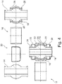
- the outer housing 16 is made in two parts. It consists of two sleeves 16A, 16B which each have an inwardly protruding shoulder 36 on the axial side that faces away from the center of the ball joint in the assembled state.
- the shoulders 36 functionally have the same effect as the radial widenings 28 on the inner housing 18 in the second embodiment: a seat for the bead 32 of the sealing bellows 30 is formed.
- the two sleeves 16A, 16B of the outer housing 16 are welded to the inner housing 18.
- circumferential weld seams 38 can be used which establish a connection between the corresponding sleeve 16A, 16B and the circumferential collar 24 of the inner housing 18.
- the shoulders 36 engage here in a circumferential groove in the bead 32 of the sealing bellows 30.
- Other connection configurations can also be used at this point.
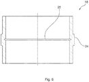
- the inner housing 18 is designed with a radial widening 28.
- the plastic deformation leads to a "fold" in the wall of the inner housing, which can be seen on the inside as a circumferential groove 25.
- the fold can be produced by locally pressing the blank of the inner housing 18 in the radial direction outward, or by axially compressing the entire blank in such a way that the wall deviates outward at the desired point.
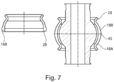
- Figure 7 the inner housing for a ball joint according to a fourth embodiment is shown in a schematic cross section.
- the same reference numerals are used for the components and features known from the previous embodiments, and reference is made to the above explanations.
- the inner housing 18 is composed of two half-shells 18A, 18B.
- the two half-shells 18A, 18B are fastened to one another by being welded to one another (see the schematically indicated weld seam 40). This extends in the circumferential direction at the "equator" of the ball joint.
- Each of the half-shells 18A, 18B can be provided with a radial widening 28 in order to be able to accommodate a bead of a sealing bellows there.
- the difference between the fifth embodiment and the previous embodiments is that the inner housing is not provided with a circumferential collar 24 which is used to fasten the outer housing 16 to the inner housing 18. Instead, two support rings 42 are used, which are arranged at the axial ends of the housing 12 and are welded to both the outer housing 16 and the inner housing 18 (see the weld seams 44 indicated schematically).
- the housing formed in this way is very rigid overall and at the same time has a very low weight.
- a particular advantage is that there is a small free space F in the radial direction between the outer surface of the inner housing 18 and the inner surface of the outer housing 16 in the area of the equator of the ball joint. If the outer housing 16 is slightly deformed inwards in this area, this deformation is not transferred to the inner housing 18. Accordingly, deformation of the outer housing 16 does not result in a change in the frictional force of the ball joint.
Landscapes
- Engineering & Computer Science (AREA)
- General Engineering & Computer Science (AREA)
- Mechanical Engineering (AREA)
- Pivots And Pivotal Connections (AREA)
Claims (8)
- Articulation sphérique (10) comprenant un boîtier extérieur annulaire (16) qui est composé d'au moins une douille en tôle, un boîtier intérieur annulaire (18) qui est reçu de manière solidaire dans le boîtier extérieur (16) dans le sens axial et qui est composé d'au moins une douille métallique, un coussinet de palier (20) qui est reçu dans le boîtier intérieur (18), et un tourillon sphérique (14) qui est reçu dans le coussinet de palier (20), caractérisée en ce que deux anneaux de support (42) qui sont soudés au boîtier intérieur (18) et au boîtier extérieur (16) sont prévus entre le boîtier intérieur (18) et le boîtier extérieur (16), un espace libre (F) étant présent entre la paroi intérieure du boîtier extérieur (16) et la paroi extérieure du boîtier intérieur (18).
- Articulation sphérique selon la revendication 1, caractérisée en ce que le boîtier intérieur (18) est une pièce en tôle.
- Articulation sphérique (10) selon l'une des revendications précédentes, caractérisée en ce que le boîtier intérieur (18) présente à ses extrémités axiales un évasement radial (28), qui sert respectivement de siège pour un soufflet d'étanchéité (30).
- Articulation sphérique (10) selon l'une des revendications précédentes, caractérisée en ce que le boîtier extérieur (16) est composé d'une douille réalisée d'un seul tenant.
- Articulation sphérique (10) selon l'une des revendications précédentes, caractérisée en ce que le boîtier intérieur (18) est formé de deux demi-coquilles (18A, 18B) soudées l'une à l'autre.
- Articulation sphérique (10) selon l'une des revendications précédentes, caractérisée en ce que le boîtier extérieur (16) est composé d'une bande de tôle qui est façonnée de manière à former une douille, deux bords longitudinaux opposés l'un à l'autre et s'étendant dans le sens axial étant soudés l'un à l'autre.
- Articulation sphérique (10) selon l'une des revendications précédentes, caractérisée en ce que le boîtier intérieur (18) est composé d'une bande de tôle qui est façonnée de manière à former une douille, deux bords longitudinaux opposés l'un à l'autre et s'étendant dans le sens axial étant soudés l'un à l'autre.
- Articulation sphérique (10) selon l'une des revendications précédentes, caractérisée en ce que le tourillon sphérique (14) est creux et en ce qu'il s'agit d'une articulation à enfoncer.
Applications Claiming Priority (2)
| Application Number | Priority Date | Filing Date | Title |
|---|---|---|---|
| DE102017118030.3A DE102017118030A1 (de) | 2017-08-08 | 2017-08-08 | Kugelgelenk |
| EP18184511.6A EP3441633B1 (fr) | 2017-08-08 | 2018-07-19 | Joint pivotant |
Related Parent Applications (2)
| Application Number | Title | Priority Date | Filing Date |
|---|---|---|---|
| EP18184511.6A Division EP3441633B1 (fr) | 2017-08-08 | 2018-07-19 | Joint pivotant |
| EP18184511.6A Division-Into EP3441633B1 (fr) | 2017-08-08 | 2018-07-19 | Joint pivotant |
Publications (2)
| Publication Number | Publication Date |
|---|---|
| EP3608552A1 EP3608552A1 (fr) | 2020-02-12 |
| EP3608552B1 true EP3608552B1 (fr) | 2021-02-17 |
Family
ID=63012922
Family Applications (2)
| Application Number | Title | Priority Date | Filing Date |
|---|---|---|---|
| EP19199949.9A Active EP3608552B1 (fr) | 2017-08-08 | 2018-07-19 | Joint pivotant |
| EP18184511.6A Active EP3441633B1 (fr) | 2017-08-08 | 2018-07-19 | Joint pivotant |
Family Applications After (1)
| Application Number | Title | Priority Date | Filing Date |
|---|---|---|---|
| EP18184511.6A Active EP3441633B1 (fr) | 2017-08-08 | 2018-07-19 | Joint pivotant |
Country Status (3)
| Country | Link |
|---|---|
| EP (2) | EP3608552B1 (fr) |
| DE (1) | DE102017118030A1 (fr) |
| ES (1) | ES2817839T3 (fr) |
Cited By (1)
| Publication number | Priority date | Publication date | Assignee | Title |
|---|---|---|---|---|
| US11286975B2 (en) * | 2020-04-24 | 2022-03-29 | THK RHYTHM AUTOMOTIVE GmbH | Ball stud and method of manufacturing a ball stud |
Family Cites Families (9)
| Publication number | Priority date | Publication date | Assignee | Title |
|---|---|---|---|---|
| DE1552120A1 (de) * | 1965-07-19 | 1969-11-20 | White Charles Samuel | Verfahren und Vorrichtung zum Herstellen von Ringlagern |
| US3418706A (en) * | 1967-09-25 | 1968-12-31 | Charles S. White | Method and apparatus for making bearings |
| DE3613808A1 (de) * | 1986-04-24 | 1987-10-29 | Ilie Chivari | Kugelgelenk |
| DE3731586A1 (de) * | 1987-09-19 | 1989-04-06 | Durbal Gmbh & Co | Gelenklager und verfahren zur herstellung desselben |
| DE10358763B4 (de) * | 2003-12-12 | 2005-12-29 | Zf Friedrichshafen Ag | Kugelhülsengelenk |
| US8985604B2 (en) * | 2010-07-07 | 2015-03-24 | Ford Global Technologies, Llc | Cross axis joint with elastomeric isolation |
| WO2012026778A2 (fr) * | 2010-08-27 | 2012-03-01 | 주식회사 센트랄엘티에스 | Joint à rotule à coussinet pour automobile |
| DE102010041306A1 (de) * | 2010-09-24 | 2012-03-29 | Zf Friedrichshafen Ag | Verfahren zum Herstellen eines Kugelhülsengelenks |
| DE102012207527B4 (de) * | 2012-05-07 | 2022-12-29 | Zf Friedrichshafen Ag | Hülsengelenk für ein Fahrzeug |
-
2017
- 2017-08-08 DE DE102017118030.3A patent/DE102017118030A1/de not_active Withdrawn
-
2018
- 2018-07-19 EP EP19199949.9A patent/EP3608552B1/fr active Active
- 2018-07-19 EP EP18184511.6A patent/EP3441633B1/fr active Active
- 2018-07-19 ES ES18184511T patent/ES2817839T3/es active Active
Non-Patent Citations (1)
| Title |
|---|
| None * |
Cited By (1)
| Publication number | Priority date | Publication date | Assignee | Title |
|---|---|---|---|---|
| US11286975B2 (en) * | 2020-04-24 | 2022-03-29 | THK RHYTHM AUTOMOTIVE GmbH | Ball stud and method of manufacturing a ball stud |
Also Published As
| Publication number | Publication date |
|---|---|
| EP3441633A1 (fr) | 2019-02-13 |
| DE102017118030A1 (de) | 2019-02-14 |
| EP3608552A1 (fr) | 2020-02-12 |
| ES2817839T3 (es) | 2021-04-08 |
| EP3441633B1 (fr) | 2020-06-17 |
Similar Documents
| Publication | Publication Date | Title |
|---|---|---|
| EP2449274B1 (fr) | Joint à rotule | |
| DE69215290T2 (de) | Verstellbare Buchse | |
| EP1781957A1 (fr) | Articulation a douille a rotule et procede pour sa production | |
| DE60019662T2 (de) | Lager für Radnabe eines Motorfahrzeuges und Befestigungsverfahren des Lagers in einer Motorfahrzeugaufhängung | |
| DE10115373C1 (de) | Gelenkstütze für ein Kolben-Zylinderaggregat | |
| EP2018280B1 (fr) | Système d'assemblage sur un véhicule automobile entre une bague extérieure d'un palier à roulement et un support de roue et procédé de fabrication d'un système d'assemblage de ce type | |
| EP1502011B1 (fr) | Came monobloc, son procede de fabrication, et assemblage d'un arbre de commande ou arbre a came | |
| EP1456544B1 (fr) | Articulation spherique | |
| DE102009031738B4 (de) | Kugelgelenk | |
| EP2265834A1 (fr) | Cage pour palier à roulement | |
| EP3608552B1 (fr) | Joint pivotant | |
| EP1815155A1 (fr) | Ensemble d'articulation et/ou de logement | |
| WO2018050351A1 (fr) | Procédé de fabrication d'une pièce de véhicule | |
| EP1818560B1 (fr) | Articulation, en particulier pour suspension de roue avant indépendante dans un véhicule industriel | |
| DE3332771C2 (fr) | ||
| DE202006000285U1 (de) | Elastomer-Metall-Gelenklager, insbesondere als Zentralgelenklager eines Dreieckslenkers zur Verbindung eines Achskörpers mit einem Fahrzeugaufbau | |
| WO2018192601A1 (fr) | Stabilisateur de roulis pour véhicule automobile | |
| EP3554867B1 (fr) | Articulation pour un véhicule et procédé permettant de fabriquer une telle articulation | |
| EP3988352A1 (fr) | Bras de liaison pour un châssis d'un véhicule automobile | |
| BE1030972B1 (de) | Verfahren zur Herstellung einer Verbindung zwischen einer Welle und einer Gelenkgabel eines Lenksystems für ein Kraftfahrzeug und Lenksystem für ein Kraftfahrzeug | |
| EP1454073A1 (fr) | Joint a rotule | |
| DE102020111280A1 (de) | Kugelzapfen sowie Verfahren zur Herstellung eines Kugelzapfens | |
| EP4585821A2 (fr) | Ensemble palier et procédé de fabrication d'un ensemble palier | |
| WO2011110154A1 (fr) | Cage d'articulation à rotule et articulation à rotule | |
| DE102021201721A1 (de) | Mehrpunktlenker für ein Fahrwerk |
Legal Events
| Date | Code | Title | Description |
|---|---|---|---|
| PUAI | Public reference made under article 153(3) epc to a published international application that has entered the european phase |
Free format text: ORIGINAL CODE: 0009012 |
|
| STAA | Information on the status of an ep patent application or granted ep patent |
Free format text: STATUS: THE APPLICATION HAS BEEN PUBLISHED |
|
| STAA | Information on the status of an ep patent application or granted ep patent |
Free format text: STATUS: REQUEST FOR EXAMINATION WAS MADE |
|
| AC | Divisional application: reference to earlier application |
Ref document number: 3441633 Country of ref document: EP Kind code of ref document: P |
|
| AK | Designated contracting states |
Kind code of ref document: A1 Designated state(s): AL AT BE BG CH CY CZ DE DK EE ES FI FR GB GR HR HU IE IS IT LI LT LU LV MC MK MT NL NO PL PT RO RS SE SI SK SM TR |
|
| AX | Request for extension of the european patent |
Extension state: BA ME |
|
| 17P | Request for examination filed |
Effective date: 20200117 |
|
| RBV | Designated contracting states (corrected) |
Designated state(s): AL AT BE BG CH CY CZ DE DK EE ES FI FR GB GR HR HU IE IS IT LI LT LU LV MC MK MT NL NO PL PT RO RS SE SI SK SM TR |
|
| STAA | Information on the status of an ep patent application or granted ep patent |
Free format text: STATUS: EXAMINATION IS IN PROGRESS |
|
| 17Q | First examination report despatched |
Effective date: 20200702 |
|
| GRAP | Despatch of communication of intention to grant a patent |
Free format text: ORIGINAL CODE: EPIDOSNIGR1 |
|
| STAA | Information on the status of an ep patent application or granted ep patent |
Free format text: STATUS: GRANT OF PATENT IS INTENDED |
|
| INTG | Intention to grant announced |
Effective date: 20200831 |
|
| GRAS | Grant fee paid |
Free format text: ORIGINAL CODE: EPIDOSNIGR3 |
|
| GRAA | (expected) grant |
Free format text: ORIGINAL CODE: 0009210 |
|
| STAA | Information on the status of an ep patent application or granted ep patent |
Free format text: STATUS: THE PATENT HAS BEEN GRANTED |
|
| AC | Divisional application: reference to earlier application |
Ref document number: 3441633 Country of ref document: EP Kind code of ref document: P |
|
| AK | Designated contracting states |
Kind code of ref document: B1 Designated state(s): AL AT BE BG CH CY CZ DE DK EE ES FI FR GB GR HR HU IE IS IT LI LT LU LV MC MK MT NL NO PL PT RO RS SE SI SK SM TR |
|
| REG | Reference to a national code |
Ref country code: GB Ref legal event code: FG4D Free format text: NOT ENGLISH |
|
| REG | Reference to a national code |
Ref country code: CH Ref legal event code: EP |
|
| REG | Reference to a national code |
Ref country code: DE Ref legal event code: R096 Ref document number: 502018003943 Country of ref document: DE |
|
| REG | Reference to a national code |
Ref country code: AT Ref legal event code: REF Ref document number: 1361872 Country of ref document: AT Kind code of ref document: T Effective date: 20210315 |
|
| REG | Reference to a national code |
Ref country code: IE Ref legal event code: FG4D Free format text: LANGUAGE OF EP DOCUMENT: GERMAN |
|
| REG | Reference to a national code |
Ref country code: LT Ref legal event code: MG9D |
|
| REG | Reference to a national code |
Ref country code: NL Ref legal event code: MP Effective date: 20210217 |
|
| PG25 | Lapsed in a contracting state [announced via postgrant information from national office to epo] |
Ref country code: LT Free format text: LAPSE BECAUSE OF FAILURE TO SUBMIT A TRANSLATION OF THE DESCRIPTION OR TO PAY THE FEE WITHIN THE PRESCRIBED TIME-LIMIT Effective date: 20210217 Ref country code: NO Free format text: LAPSE BECAUSE OF FAILURE TO SUBMIT A TRANSLATION OF THE DESCRIPTION OR TO PAY THE FEE WITHIN THE PRESCRIBED TIME-LIMIT Effective date: 20210517 Ref country code: PT Free format text: LAPSE BECAUSE OF FAILURE TO SUBMIT A TRANSLATION OF THE DESCRIPTION OR TO PAY THE FEE WITHIN THE PRESCRIBED TIME-LIMIT Effective date: 20210617 Ref country code: BG Free format text: LAPSE BECAUSE OF FAILURE TO SUBMIT A TRANSLATION OF THE DESCRIPTION OR TO PAY THE FEE WITHIN THE PRESCRIBED TIME-LIMIT Effective date: 20210517 Ref country code: HR Free format text: LAPSE BECAUSE OF FAILURE TO SUBMIT A TRANSLATION OF THE DESCRIPTION OR TO PAY THE FEE WITHIN THE PRESCRIBED TIME-LIMIT Effective date: 20210217 Ref country code: GR Free format text: LAPSE BECAUSE OF FAILURE TO SUBMIT A TRANSLATION OF THE DESCRIPTION OR TO PAY THE FEE WITHIN THE PRESCRIBED TIME-LIMIT Effective date: 20210518 Ref country code: FI Free format text: LAPSE BECAUSE OF FAILURE TO SUBMIT A TRANSLATION OF THE DESCRIPTION OR TO PAY THE FEE WITHIN THE PRESCRIBED TIME-LIMIT Effective date: 20210217 |
|
| PG25 | Lapsed in a contracting state [announced via postgrant information from national office to epo] |
Ref country code: SE Free format text: LAPSE BECAUSE OF FAILURE TO SUBMIT A TRANSLATION OF THE DESCRIPTION OR TO PAY THE FEE WITHIN THE PRESCRIBED TIME-LIMIT Effective date: 20210217 Ref country code: RS Free format text: LAPSE BECAUSE OF FAILURE TO SUBMIT A TRANSLATION OF THE DESCRIPTION OR TO PAY THE FEE WITHIN THE PRESCRIBED TIME-LIMIT Effective date: 20210217 Ref country code: PL Free format text: LAPSE BECAUSE OF FAILURE TO SUBMIT A TRANSLATION OF THE DESCRIPTION OR TO PAY THE FEE WITHIN THE PRESCRIBED TIME-LIMIT Effective date: 20210217 Ref country code: NL Free format text: LAPSE BECAUSE OF FAILURE TO SUBMIT A TRANSLATION OF THE DESCRIPTION OR TO PAY THE FEE WITHIN THE PRESCRIBED TIME-LIMIT Effective date: 20210217 Ref country code: LV Free format text: LAPSE BECAUSE OF FAILURE TO SUBMIT A TRANSLATION OF THE DESCRIPTION OR TO PAY THE FEE WITHIN THE PRESCRIBED TIME-LIMIT Effective date: 20210217 |
|
| PG25 | Lapsed in a contracting state [announced via postgrant information from national office to epo] |
Ref country code: IS Free format text: LAPSE BECAUSE OF FAILURE TO SUBMIT A TRANSLATION OF THE DESCRIPTION OR TO PAY THE FEE WITHIN THE PRESCRIBED TIME-LIMIT Effective date: 20210617 |
|
| PG25 | Lapsed in a contracting state [announced via postgrant information from national office to epo] |
Ref country code: EE Free format text: LAPSE BECAUSE OF FAILURE TO SUBMIT A TRANSLATION OF THE DESCRIPTION OR TO PAY THE FEE WITHIN THE PRESCRIBED TIME-LIMIT Effective date: 20210217 Ref country code: CZ Free format text: LAPSE BECAUSE OF FAILURE TO SUBMIT A TRANSLATION OF THE DESCRIPTION OR TO PAY THE FEE WITHIN THE PRESCRIBED TIME-LIMIT Effective date: 20210217 Ref country code: SM Free format text: LAPSE BECAUSE OF FAILURE TO SUBMIT A TRANSLATION OF THE DESCRIPTION OR TO PAY THE FEE WITHIN THE PRESCRIBED TIME-LIMIT Effective date: 20210217 |
|
| REG | Reference to a national code |
Ref country code: DE Ref legal event code: R097 Ref document number: 502018003943 Country of ref document: DE |
|
| PG25 | Lapsed in a contracting state [announced via postgrant information from national office to epo] |
Ref country code: SK Free format text: LAPSE BECAUSE OF FAILURE TO SUBMIT A TRANSLATION OF THE DESCRIPTION OR TO PAY THE FEE WITHIN THE PRESCRIBED TIME-LIMIT Effective date: 20210217 Ref country code: RO Free format text: LAPSE BECAUSE OF FAILURE TO SUBMIT A TRANSLATION OF THE DESCRIPTION OR TO PAY THE FEE WITHIN THE PRESCRIBED TIME-LIMIT Effective date: 20210217 Ref country code: DK Free format text: LAPSE BECAUSE OF FAILURE TO SUBMIT A TRANSLATION OF THE DESCRIPTION OR TO PAY THE FEE WITHIN THE PRESCRIBED TIME-LIMIT Effective date: 20210217 |
|
| PLBE | No opposition filed within time limit |
Free format text: ORIGINAL CODE: 0009261 |
|
| STAA | Information on the status of an ep patent application or granted ep patent |
Free format text: STATUS: NO OPPOSITION FILED WITHIN TIME LIMIT |
|
| 26N | No opposition filed |
Effective date: 20211118 |
|
| PG25 | Lapsed in a contracting state [announced via postgrant information from national office to epo] |
Ref country code: ES Free format text: LAPSE BECAUSE OF FAILURE TO SUBMIT A TRANSLATION OF THE DESCRIPTION OR TO PAY THE FEE WITHIN THE PRESCRIBED TIME-LIMIT Effective date: 20210217 Ref country code: AL Free format text: LAPSE BECAUSE OF FAILURE TO SUBMIT A TRANSLATION OF THE DESCRIPTION OR TO PAY THE FEE WITHIN THE PRESCRIBED TIME-LIMIT Effective date: 20210217 |
|
| PG25 | Lapsed in a contracting state [announced via postgrant information from national office to epo] |
Ref country code: SI Free format text: LAPSE BECAUSE OF FAILURE TO SUBMIT A TRANSLATION OF THE DESCRIPTION OR TO PAY THE FEE WITHIN THE PRESCRIBED TIME-LIMIT Effective date: 20210217 |
|
| REG | Reference to a national code |
Ref country code: CH Ref legal event code: PL |
|
| PG25 | Lapsed in a contracting state [announced via postgrant information from national office to epo] |
Ref country code: MC Free format text: LAPSE BECAUSE OF FAILURE TO SUBMIT A TRANSLATION OF THE DESCRIPTION OR TO PAY THE FEE WITHIN THE PRESCRIBED TIME-LIMIT Effective date: 20210217 |
|
| REG | Reference to a national code |
Ref country code: BE Ref legal event code: MM Effective date: 20210731 |
|
| PG25 | Lapsed in a contracting state [announced via postgrant information from national office to epo] |
Ref country code: LI Free format text: LAPSE BECAUSE OF NON-PAYMENT OF DUE FEES Effective date: 20210731 Ref country code: CH Free format text: LAPSE BECAUSE OF NON-PAYMENT OF DUE FEES Effective date: 20210731 |
|
| PG25 | Lapsed in a contracting state [announced via postgrant information from national office to epo] |
Ref country code: IS Free format text: LAPSE BECAUSE OF FAILURE TO SUBMIT A TRANSLATION OF THE DESCRIPTION OR TO PAY THE FEE WITHIN THE PRESCRIBED TIME-LIMIT Effective date: 20210617 Ref country code: LU Free format text: LAPSE BECAUSE OF NON-PAYMENT OF DUE FEES Effective date: 20210719 |
|
| PG25 | Lapsed in a contracting state [announced via postgrant information from national office to epo] |
Ref country code: IE Free format text: LAPSE BECAUSE OF NON-PAYMENT OF DUE FEES Effective date: 20210719 Ref country code: BE Free format text: LAPSE BECAUSE OF NON-PAYMENT OF DUE FEES Effective date: 20210731 |
|
| PG25 | Lapsed in a contracting state [announced via postgrant information from national office to epo] |
Ref country code: CY Free format text: LAPSE BECAUSE OF FAILURE TO SUBMIT A TRANSLATION OF THE DESCRIPTION OR TO PAY THE FEE WITHIN THE PRESCRIBED TIME-LIMIT Effective date: 20210217 |
|
| PG25 | Lapsed in a contracting state [announced via postgrant information from national office to epo] |
Ref country code: HU Free format text: LAPSE BECAUSE OF FAILURE TO SUBMIT A TRANSLATION OF THE DESCRIPTION OR TO PAY THE FEE WITHIN THE PRESCRIBED TIME-LIMIT; INVALID AB INITIO Effective date: 20180719 |
|
| PGFP | Annual fee paid to national office [announced via postgrant information from national office to epo] |
Ref country code: GB Payment date: 20230721 Year of fee payment: 6 |
|
| PG25 | Lapsed in a contracting state [announced via postgrant information from national office to epo] |
Ref country code: MK Free format text: LAPSE BECAUSE OF FAILURE TO SUBMIT A TRANSLATION OF THE DESCRIPTION OR TO PAY THE FEE WITHIN THE PRESCRIBED TIME-LIMIT Effective date: 20210217 |
|
| PG25 | Lapsed in a contracting state [announced via postgrant information from national office to epo] |
Ref country code: TR Free format text: LAPSE BECAUSE OF FAILURE TO SUBMIT A TRANSLATION OF THE DESCRIPTION OR TO PAY THE FEE WITHIN THE PRESCRIBED TIME-LIMIT Effective date: 20210217 |
|
| REG | Reference to a national code |
Ref country code: AT Ref legal event code: MM01 Ref document number: 1361872 Country of ref document: AT Kind code of ref document: T Effective date: 20230719 |
|
| PG25 | Lapsed in a contracting state [announced via postgrant information from national office to epo] |
Ref country code: MT Free format text: LAPSE BECAUSE OF FAILURE TO SUBMIT A TRANSLATION OF THE DESCRIPTION OR TO PAY THE FEE WITHIN THE PRESCRIBED TIME-LIMIT Effective date: 20210217 |
|
| PGFP | Annual fee paid to national office [announced via postgrant information from national office to epo] |
Ref country code: DE Payment date: 20240718 Year of fee payment: 7 |
|
| PGFP | Annual fee paid to national office [announced via postgrant information from national office to epo] |
Ref country code: FR Payment date: 20240730 Year of fee payment: 7 |
|
| PG25 | Lapsed in a contracting state [announced via postgrant information from national office to epo] |
Ref country code: AT Free format text: LAPSE BECAUSE OF NON-PAYMENT OF DUE FEES Effective date: 20230719 |
|
| PG25 | Lapsed in a contracting state [announced via postgrant information from national office to epo] |
Ref country code: AT Free format text: LAPSE BECAUSE OF NON-PAYMENT OF DUE FEES Effective date: 20230719 |
|
| PGFP | Annual fee paid to national office [announced via postgrant information from national office to epo] |
Ref country code: IT Payment date: 20240725 Year of fee payment: 7 |
|
| GBPC | Gb: european patent ceased through non-payment of renewal fee |
Effective date: 20240719 |
|
| PG25 | Lapsed in a contracting state [announced via postgrant information from national office to epo] |
Ref country code: GB Free format text: LAPSE BECAUSE OF NON-PAYMENT OF DUE FEES Effective date: 20240719 |
|
| REG | Reference to a national code |
Ref country code: DE Ref legal event code: R119 Ref document number: 502018003943 Country of ref document: DE |
|
| PG25 | Lapsed in a contracting state [announced via postgrant information from national office to epo] |
Ref country code: DE Free format text: LAPSE BECAUSE OF NON-PAYMENT OF DUE FEES Effective date: 20260203 |
|
| PGFP | Annual fee paid to national office [announced via postgrant information from national office to epo] |
Ref country code: AT Payment date: 20260410 Year of fee payment: 5 |
|
| PG25 | Lapsed in a contracting state [announced via postgrant information from national office to epo] |
Ref country code: FR Free format text: LAPSE BECAUSE OF NON-PAYMENT OF DUE FEES Effective date: 20250731 |