EP3608512A1 - Gas turbine engine with sealing surface for blade outer air seal - Google Patents
Gas turbine engine with sealing surface for blade outer air seal Download PDFInfo
- Publication number
- EP3608512A1 EP3608512A1 EP19189443.5A EP19189443A EP3608512A1 EP 3608512 A1 EP3608512 A1 EP 3608512A1 EP 19189443 A EP19189443 A EP 19189443A EP 3608512 A1 EP3608512 A1 EP 3608512A1
- Authority
- EP
- European Patent Office
- Prior art keywords
- sealing surface
- seal
- gas turbine
- radially
- turbine engine
- Prior art date
- Legal status (The legal status is an assumption and is not a legal conclusion. Google has not performed a legal analysis and makes no representation as to the accuracy of the status listed.)
- Granted
Links
Images


Classifications
-
- F—MECHANICAL ENGINEERING; LIGHTING; HEATING; WEAPONS; BLASTING
- F01—MACHINES OR ENGINES IN GENERAL; ENGINE PLANTS IN GENERAL; STEAM ENGINES
- F01D—NON-POSITIVE DISPLACEMENT MACHINES OR ENGINES, e.g. STEAM TURBINES
- F01D11/00—Preventing or minimising internal leakage of working-fluid, e.g. between stages
- F01D11/08—Preventing or minimising internal leakage of working-fluid, e.g. between stages for sealing space between rotor blade tips and stator
-
- F—MECHANICAL ENGINEERING; LIGHTING; HEATING; WEAPONS; BLASTING
- F01—MACHINES OR ENGINES IN GENERAL; ENGINE PLANTS IN GENERAL; STEAM ENGINES
- F01D—NON-POSITIVE DISPLACEMENT MACHINES OR ENGINES, e.g. STEAM TURBINES
- F01D11/00—Preventing or minimising internal leakage of working-fluid, e.g. between stages
- F01D11/005—Sealing means between non relatively rotating elements
-
- F—MECHANICAL ENGINEERING; LIGHTING; HEATING; WEAPONS; BLASTING
- F01—MACHINES OR ENGINES IN GENERAL; ENGINE PLANTS IN GENERAL; STEAM ENGINES
- F01D—NON-POSITIVE DISPLACEMENT MACHINES OR ENGINES, e.g. STEAM TURBINES
- F01D25/00—Component parts, details, or accessories, not provided for in, or of interest apart from, other groups
- F01D25/24—Casings; Casing parts, e.g. diaphragms, casing fastenings
- F01D25/246—Fastening of diaphragms or stator-rings
-
- F—MECHANICAL ENGINEERING; LIGHTING; HEATING; WEAPONS; BLASTING
- F05—INDEXING SCHEMES RELATING TO ENGINES OR PUMPS IN VARIOUS SUBCLASSES OF CLASSES F01-F04
- F05D—INDEXING SCHEME FOR ASPECTS RELATING TO NON-POSITIVE-DISPLACEMENT MACHINES OR ENGINES, GAS-TURBINES OR JET-PROPULSION PLANTS
- F05D2220/00—Application
- F05D2220/30—Application in turbines
- F05D2220/32—Application in turbines in gas turbines
- F05D2220/323—Application in turbines in gas turbines for aircraft propulsion, e.g. jet engines
-
- F—MECHANICAL ENGINEERING; LIGHTING; HEATING; WEAPONS; BLASTING
- F05—INDEXING SCHEMES RELATING TO ENGINES OR PUMPS IN VARIOUS SUBCLASSES OF CLASSES F01-F04
- F05D—INDEXING SCHEME FOR ASPECTS RELATING TO NON-POSITIVE-DISPLACEMENT MACHINES OR ENGINES, GAS-TURBINES OR JET-PROPULSION PLANTS
- F05D2240/00—Components
- F05D2240/10—Stators
- F05D2240/11—Shroud seal segments
-
- F—MECHANICAL ENGINEERING; LIGHTING; HEATING; WEAPONS; BLASTING
- F05—INDEXING SCHEMES RELATING TO ENGINES OR PUMPS IN VARIOUS SUBCLASSES OF CLASSES F01-F04
- F05D—INDEXING SCHEME FOR ASPECTS RELATING TO NON-POSITIVE-DISPLACEMENT MACHINES OR ENGINES, GAS-TURBINES OR JET-PROPULSION PLANTS
- F05D2240/00—Components
- F05D2240/55—Seals
-
- F—MECHANICAL ENGINEERING; LIGHTING; HEATING; WEAPONS; BLASTING
- F05—INDEXING SCHEMES RELATING TO ENGINES OR PUMPS IN VARIOUS SUBCLASSES OF CLASSES F01-F04
- F05D—INDEXING SCHEME FOR ASPECTS RELATING TO NON-POSITIVE-DISPLACEMENT MACHINES OR ENGINES, GAS-TURBINES OR JET-PROPULSION PLANTS
- F05D2240/00—Components
- F05D2240/55—Seals
- F05D2240/56—Brush seals
-
- F—MECHANICAL ENGINEERING; LIGHTING; HEATING; WEAPONS; BLASTING
- F05—INDEXING SCHEMES RELATING TO ENGINES OR PUMPS IN VARIOUS SUBCLASSES OF CLASSES F01-F04
- F05D—INDEXING SCHEME FOR ASPECTS RELATING TO NON-POSITIVE-DISPLACEMENT MACHINES OR ENGINES, GAS-TURBINES OR JET-PROPULSION PLANTS
- F05D2240/00—Components
- F05D2240/55—Seals
- F05D2240/57—Leaf seals
-
- F—MECHANICAL ENGINEERING; LIGHTING; HEATING; WEAPONS; BLASTING
- F05—INDEXING SCHEMES RELATING TO ENGINES OR PUMPS IN VARIOUS SUBCLASSES OF CLASSES F01-F04
- F05D—INDEXING SCHEME FOR ASPECTS RELATING TO NON-POSITIVE-DISPLACEMENT MACHINES OR ENGINES, GAS-TURBINES OR JET-PROPULSION PLANTS
- F05D2250/00—Geometry
- F05D2250/70—Shape
- F05D2250/75—Shape given by its similarity to a letter, e.g. T-shaped
-
- F—MECHANICAL ENGINEERING; LIGHTING; HEATING; WEAPONS; BLASTING
- F05—INDEXING SCHEMES RELATING TO ENGINES OR PUMPS IN VARIOUS SUBCLASSES OF CLASSES F01-F04
- F05D—INDEXING SCHEME FOR ASPECTS RELATING TO NON-POSITIVE-DISPLACEMENT MACHINES OR ENGINES, GAS-TURBINES OR JET-PROPULSION PLANTS
- F05D2300/00—Materials; Properties thereof
- F05D2300/10—Metals, alloys or intermetallic compounds
- F05D2300/16—Other metals not provided for in groups F05D2300/11 - F05D2300/15
-
- F—MECHANICAL ENGINEERING; LIGHTING; HEATING; WEAPONS; BLASTING
- F05—INDEXING SCHEMES RELATING TO ENGINES OR PUMPS IN VARIOUS SUBCLASSES OF CLASSES F01-F04
- F05D—INDEXING SCHEME FOR ASPECTS RELATING TO NON-POSITIVE-DISPLACEMENT MACHINES OR ENGINES, GAS-TURBINES OR JET-PROPULSION PLANTS
- F05D2300/00—Materials; Properties thereof
- F05D2300/10—Metals, alloys or intermetallic compounds
- F05D2300/17—Alloys
-
- F—MECHANICAL ENGINEERING; LIGHTING; HEATING; WEAPONS; BLASTING
- F05—INDEXING SCHEMES RELATING TO ENGINES OR PUMPS IN VARIOUS SUBCLASSES OF CLASSES F01-F04
- F05D—INDEXING SCHEME FOR ASPECTS RELATING TO NON-POSITIVE-DISPLACEMENT MACHINES OR ENGINES, GAS-TURBINES OR JET-PROPULSION PLANTS
- F05D2300/00—Materials; Properties thereof
- F05D2300/60—Properties or characteristics given to material by treatment or manufacturing
- F05D2300/603—Composites; e.g. fibre-reinforced
- F05D2300/6033—Ceramic matrix composites [CMC]
Definitions
- This application relates to a sealing surface associated with a forward hook in a ceramic matrix composite blade outer air seal.
- Gas turbine engines typically include a fan delivering air into a compressor. The air is compressed and delivered into a combustion section where it is mixed with fuel and ignited. Products of the combustion pass downstream over turbine rotors, driving them to rotate.
- BOAS blade outer air seal
- seals are associated with the blade outer air seal.
- the seals prevent leakage radially outwardly around the BOAS.
- a gas turbine engine that includes a turbine section having a turbine rotor and at least one blade extending outwardly of the turbine rotor.
- the turbine rotor rotates about an axis of rotation.
- a blade outer air seal is positioned radially outward of the at least one blade.
- the blade outer air seal has an axially forward hook and an axially aft hook supported to static structure.
- An axial seal is attached to static structure forward of the forward hook, and has a sealing portion extending in an aft direction.
- a sealing surface member is positioned intermediate an aft end of the axial seal and a forward end of the forward hook to provide a sealing surface for sealing between the seal and the blade outer air seal.
- the blade outer air seal is formed of ceramic matrix composite materials.
- the forward hook has a curved portion extending from a blade outer air seal body into the forward hook.
- the seal is radially aligned with the curved portion such that the sealing surface member provides a sealing surface in place of the curved portion.
- the sealing surface member has a generally radially extending portion extending radially inwardly to a curved sealing surface member portion curving in a forward direction relative to the generally radially extending portion.
- the sealing surface portion is formed of one of a ceramic matrix composite material or a cobalt based alloy.
- the seal is a bristle seal having bristles with an aft end in contact with the sealing surface member.
- the bristles are formed of a cobalt alloy or cobalt steel.
- the seal is supported on a vane support which is located forward of the blade.
- the seal has a radially inwardly extending ledge.
- the radially inwardly extending ledge has a radially innermost extent which is radially inward of a radially outermost extent of a forward end of the curved portion of the seal surface member.
- the radially inwardly extending ledge has a radially innermost extent which is radially outward of a radially outermost extent of a forward end of the curved portion of the seal surface member.
- an aft extending tab extends from the generally radially extending portion of the sealing surface member and is positioned radially between the forward hook of the blade outer air seal and the static structure.
- the sealing surface member has circumferentially spaced tabs to prevent rotation relative to the static surface.
- the forward hook has a curved portion extending from a blade outer air seal body into the forward hook.
- the seal is radially aligned with the curved portion such that the sealing surface member provides a sealing surface in place of the curved portion.
- the sealing surface member has a generally radially extending portion extending radially inwardly to a curved sealing surface member portion curving in a forward direction relative to the generally radially extending portion.
- the seal is a bristle seal having bristles with an aft end in contact with the sealing surface member.
- the seal has a radially inwardly extending ledge.
- the radially inwardly extending ledge has a radially innermost extent which is radially inward of a radially outermost extent of a forward end of the curved portion of the seal surface member.
- the radially inwardly extending ledge has a radially innermost extent which is radially outward of a radially outermost extent of a forward end of the curved portion of the seal surface member.
- an aft extending tab extends from the generally radially extending portion of the sealing surface member and is positioned radially between the forward hook of the blade outer air seal and the static structure.
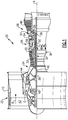
- FIG. 1 schematically illustrates a gas turbine engine 20.
- the gas turbine engine 20 is disclosed herein as a two-spool turbofan that generally incorporates a fan section 22, a compressor section 24, a combustor section 26 and a turbine section 28.
- the fan section 22 drives air along a bypass flow path B in a bypass duct defined within a nacelle 15, and also drives air along a core flow path C for compression and communication into the combustor section 26 then expansion through the turbine section 28.
- FIG. 1 schematically illustrates a gas turbine engine 20.
- the gas turbine engine 20 is disclosed herein as a two-spool turbofan that generally incorporates a fan section 22, a compressor section 24, a combustor section 26 and a turbine section 28.
- the fan section 22 drives air along a bypass flow path B in a bypass duct defined within a nacelle 15, and also drives air along a core flow path C for compression and communication into the combustor section 26 then expansion through the turbine section 28.
- FIG. 1 schematic
- the exemplary engine 20 generally includes a low speed spool 30 and a high speed spool 32 mounted for rotation about an engine central longitudinal axis A relative to an engine static structure 36 via several bearing systems 38. It should be understood that various bearing systems 38 at various locations may alternatively or additionally be provided, and the location of bearing systems 38 may be varied as appropriate to the application.
- the low speed spool 30 generally includes an inner shaft 40 that interconnects, a first (or low) pressure compressor 44 and a first (or low) pressure turbine 46.
- the inner shaft 40 is connected to the fan 42 through a speed change mechanism, which in exemplary gas turbine engine 20 is illustrated as a geared architecture 48 to drive a fan 42 at a lower speed than the low speed spool 30.
- the high speed spool 32 includes an outer shaft 50 that interconnects a second (or high) pressure compressor 52 and a second (or high) pressure turbine 54.
- a combustor 56 is arranged in exemplary gas turbine 20 between the high pressure compressor 52 and the high pressure turbine 54.
- a mid-turbine frame 57 of the engine static structure 36 may be arranged generally between the high pressure turbine 54 and the low pressure turbine 46.
- the mid-turbine frame 57 further supports bearing systems 38 in the turbine section 28.
- the inner shaft 40 and the outer shaft 50 are concentric and rotate via bearing systems 38 about the engine central longitudinal axis A which is colline
- the core airflow is compressed by the low pressure compressor 44 then the high pressure compressor 52, mixed and burned with fuel in the combustor 56, then expanded over the high pressure turbine 54 and low pressure turbine 46.
- the mid-turbine frame 57 includes airfoils 59 which are in the core airflow path C.
- the turbines 46, 54 rotationally drive the respective low speed spool 30 and high speed spool 32 in response to the expansion.
- gear system 48 may be located aft of the low pressure compressor, or aft of the combustor section 26 or even aft of turbine section 28, and fan 42 may be positioned forward or aft of the location of gear system 48.
- the engine 20 in one example is a high-bypass geared aircraft engine.
- the engine 20 bypass ratio is greater than about six, with an example embodiment being greater than about ten
- the geared architecture 48 is an epicyclic gear train, such as a planetary gear system or other gear system, with a gear reduction ratio of greater than about 2.3 and the low pressure turbine 46 has a pressure ratio that is greater than about five.
- the engine 20 bypass ratio is greater than about ten
- the fan diameter is significantly larger than that of the low pressure compressor 44
- the low pressure turbine 46 has a pressure ratio that is greater than about five.
- Low pressure turbine 46 pressure ratio is pressure measured prior to inlet of low pressure turbine 46 as related to the pressure at the outlet of the low pressure turbine 46 prior to an exhaust nozzle.
- the geared architecture 48 may be an epicycle gear train, such as a planetary gear system or other gear system, with a gear reduction ratio of greater than about 2.3:1 and less than about 5:1. It should be understood, however, that the above parameters are only exemplary of one embodiment of a geared architecture engine and that the present invention is applicable to other gas turbine engines including direct drive turbofans.
- the fan section 22 of the engine 20 is designed for a particular flight condition -- typically cruise at about 0.8 Mach and about 35,000 feet (10,668 meters).
- the flight condition of 0.8 Mach and 35,000 ft (10,668 meters), with the engine at its best fuel consumption - also known as "bucket cruise Thrust Specific Fuel Consumption ('TSFC')" - is the industry standard parameter of lbm of fuel being burned divided by lbf of thrust the engine produces at that minimum point.
- "Low fan pressure ratio” is the pressure ratio across the fan blade alone, without a Fan Exit Guide Vane (“FEGV”) system.
- the low fan pressure ratio as disclosed herein according to one non-limiting embodiment is less than about 1.45.
- the "Low corrected fan tip speed” as disclosed herein according to one non-limiting embodiment is less than about 1150 ft / second (350.5 meters/second).
- FIG. 2 shows a turbine section 100.
- a turbine blade 102 has a radially outer extent 103.
- a BOAS 104 is positioned radially outward of the tip 103.
- the BOAS 104 has a forward hook 106 and an aft hook 108.
- a support or attachment block 110 has surfaces 112 and 114 supporting the hooks 106 and 108.
- the attachment block 110 further has forward mount portion 115 and aft mount portion 116 mounting the attachment block and, hence the BOAS 104, into static structure 118.
- FIG. 3 shows an assembly according to one embodiment of this disclosure.
- a vane support 120 is attached to a static vane 121, shown schematically, and axially forward of the blade 102.
- a seal 122 is mounted on the vane support 120.
- An outer seal attachment portion 124 is shown, as is an inwardly extending lip 126.
- a seal 128 extends in an aft direction from the vane support 120 and provides a seal against hook 106.
- the bristles of seal 128 may be formed of cobalt based materials including Haynes 25 or other cobalt alloys or steels, as examples. Such materials may raise concerns if sealing against a hook 106 formed of CMC materials. (The CMC materials may also be formed from laminates.) Also, the CMC materials may be monolithic CMCs. Also, the BOAS materials may be monolithic ceramics.
- a sealing surface member 130 is positioned between an aft end 139 of the seal 128 and the hook 106.
- the sealing surface member 130 provides a surface to ensure a good seal.
- the hook 106 has a curved portion 107 in the approximate radial extent of the bristle seal 128.
- Sealing surface member 130 may be formed of an appropriate wear resistant material such as Haynes 242, a cobalt based alloy or a ceramic matrix composite material having sufficient compliance for the intended application.
- a notch 132 in static structure 118 secures the sealing surface member 130.
- the sealing surface member 130 has a radially inwardly extending straight portion 134 and a hook portion 136 that curves in a forward direction from said straight portion 134 such that the overall shape of the sealing surface member 130 is generally a J-shape.
- the inwardly extending flange 126 has a radially innermost extent 127, which is radially inward of a radially outermost extent 129 of the hook 136 at its forward most end. This provides additional support.
- the sealing surface member 130 sits between the hook 106 and the bristle seal 128. Moreover, the notch 132 provides support to secure the sealing surface member 130.
- Figure 5 shows an alternative embodiment.
- the inwardly extending flange 226 of the seal 222 has a radially inner end 250, which is radially outward of a radially outermost point 252 of the forward most end of the hook 236 of the sealing surface member 230.
- Sealing surface member 230 has a more complex tab structure 232, as will be explained below.
- tab 240 extending in an aft direction from the straight portion 234, and positioned radially intermediate the hook 106 and a portion of the support 118, which is radially inward of the hook portion 115 of the attachment block 110.
- the sealing surface member 230 has circumferentially intermediate tabs 260 extending outwardly of portions 261.
- Figures 7 shows notch 232 in static structure 118 to receive portion 261 from sealing surface member 230.
- Tabs 260 sit in anti-rotation notches 262 to prevent rotation of sealing surface member 230.
- sealing surface members are particularly valuable when utilized in combination with CMC BOAS, they may have application in metallic BOAS, or BOAS formed of other materials.
Landscapes
- Engineering & Computer Science (AREA)
- Mechanical Engineering (AREA)
- General Engineering & Computer Science (AREA)
- Turbine Rotor Nozzle Sealing (AREA)
Abstract
Description
- This application relates to a sealing surface associated with a forward hook in a ceramic matrix composite blade outer air seal.
- Gas turbine engines are known and typically include a fan delivering air into a compressor. The air is compressed and delivered into a combustion section where it is mixed with fuel and ignited. Products of the combustion pass downstream over turbine rotors, driving them to rotate.
- It is desirable to maximize the percentage of the products of combustion that pass over turbine blades on the turbine rotors. Thus, it is known to provide a blade outer air seal ("BOAS") radially outwardly of the turbine blade.
- To further maximize the percentage of the products of combustion directed across the turbine blades, seals are associated with the blade outer air seal. The seals prevent leakage radially outwardly around the BOAS.
- It has been proposed to form BOAS of ceramic matrix composite ("CMC") materials.
- In one aspect, there is provided a gas turbine engine that includes a turbine section having a turbine rotor and at least one blade extending outwardly of the turbine rotor. The turbine rotor rotates about an axis of rotation. A blade outer air seal is positioned radially outward of the at least one blade. The blade outer air seal has an axially forward hook and an axially aft hook supported to static structure. An axial seal is attached to static structure forward of the forward hook, and has a sealing portion extending in an aft direction. A sealing surface member is positioned intermediate an aft end of the axial seal and a forward end of the forward hook to provide a sealing surface for sealing between the seal and the blade outer air seal.
- In an embodiment according to the above, the blade outer air seal is formed of ceramic matrix composite materials.
- In another embodiment according to any of the above, the forward hook has a curved portion extending from a blade outer air seal body into the forward hook. The seal is radially aligned with the curved portion such that the sealing surface member provides a sealing surface in place of the curved portion.
- In another embodiment according to any of the above, the sealing surface member has a generally radially extending portion extending radially inwardly to a curved sealing surface member portion curving in a forward direction relative to the generally radially extending portion.
- In another embodiment according to any of the above, the sealing surface portion is formed of one of a ceramic matrix composite material or a cobalt based alloy.
- In another embodiment according to any of the above, the seal is a bristle seal having bristles with an aft end in contact with the sealing surface member.
- In another embodiment according to any of the above, the bristles are formed of a cobalt alloy or cobalt steel.
- In another embodiment according to any of the above, the seal is supported on a vane support which is located forward of the blade.
- In another embodiment according to any of the above, the seal has a radially inwardly extending ledge.
- In another embodiment according to any of the above, the radially inwardly extending ledge has a radially innermost extent which is radially inward of a radially outermost extent of a forward end of the curved portion of the seal surface member.
- In another embodiment according to any of the above, the radially inwardly extending ledge has a radially innermost extent which is radially outward of a radially outermost extent of a forward end of the curved portion of the seal surface member.
- In another embodiment according to any of the above, an aft extending tab extends from the generally radially extending portion of the sealing surface member and is positioned radially between the forward hook of the blade outer air seal and the static structure.
- In another embodiment according to any of the above, the sealing surface member has circumferentially spaced tabs to prevent rotation relative to the static surface.
- In another embodiment according to any of the above, the forward hook has a curved portion extending from a blade outer air seal body into the forward hook. The seal is radially aligned with the curved portion such that the sealing surface member provides a sealing surface in place of the curved portion.
- In another embodiment according to any of the above, the sealing surface member has a generally radially extending portion extending radially inwardly to a curved sealing surface member portion curving in a forward direction relative to the generally radially extending portion.
- In another embodiment according to any of the above, the seal is a bristle seal having bristles with an aft end in contact with the sealing surface member.
- In another embodiment according to any of the above, the seal has a radially inwardly extending ledge.
- In another embodiment according to any of the above, the radially inwardly extending ledge has a radially innermost extent which is radially inward of a radially outermost extent of a forward end of the curved portion of the seal surface member.
- In another embodiment according to any of the above, the radially inwardly extending ledge has a radially innermost extent which is radially outward of a radially outermost extent of a forward end of the curved portion of the seal surface member.
- In another embodiment according to any of the above, an aft extending tab extends from the generally radially extending portion of the sealing surface member and is positioned radially between the forward hook of the blade outer air seal and the static structure.
- These and other features may be best understood from the following drawings and specification.
-
-
Figure 1 schematically shows a gas turbine engine. -
Figure 2 is a schematic view of a known turbine section. -
Figure 3 shows an area of a forward hook. -
Figure 4 shows a disclosed assembly in a blade outer air seal. -
Figure 5 shows an alternative embodiment. -
Figure 6 shows an assembly of the alternative embodiment. -
Figure 7 shows a detail of theFigure 6 embodiment. -
Figure 1 schematically illustrates agas turbine engine 20. Thegas turbine engine 20 is disclosed herein as a two-spool turbofan that generally incorporates afan section 22, acompressor section 24, a combustor section 26 and aturbine section 28. Thefan section 22 drives air along a bypass flow path B in a bypass duct defined within anacelle 15, and also drives air along a core flow path C for compression and communication into the combustor section 26 then expansion through theturbine section 28. Although depicted as a two-spool turbofan gas turbine engine in the disclosed non-limiting embodiment, it should be understood that the concepts described herein are not limited to use with two-spool turbofans as the teachings may be applied to other types of turbine engines including three-spool architectures. - The
exemplary engine 20 generally includes alow speed spool 30 and ahigh speed spool 32 mounted for rotation about an engine central longitudinal axis A relative to an enginestatic structure 36 viaseveral bearing systems 38. It should be understood thatvarious bearing systems 38 at various locations may alternatively or additionally be provided, and the location ofbearing systems 38 may be varied as appropriate to the application. - The
low speed spool 30 generally includes aninner shaft 40 that interconnects, a first (or low)pressure compressor 44 and a first (or low)pressure turbine 46. Theinner shaft 40 is connected to thefan 42 through a speed change mechanism, which in exemplarygas turbine engine 20 is illustrated as a gearedarchitecture 48 to drive afan 42 at a lower speed than thelow speed spool 30. Thehigh speed spool 32 includes anouter shaft 50 that interconnects a second (or high)pressure compressor 52 and a second (or high)pressure turbine 54. Acombustor 56 is arranged inexemplary gas turbine 20 between thehigh pressure compressor 52 and thehigh pressure turbine 54. Amid-turbine frame 57 of the enginestatic structure 36 may be arranged generally between thehigh pressure turbine 54 and thelow pressure turbine 46. Themid-turbine frame 57 further supports bearingsystems 38 in theturbine section 28. Theinner shaft 40 and theouter shaft 50 are concentric and rotate viabearing systems 38 about the engine central longitudinal axis A which is collinear with their longitudinal axes. - The core airflow is compressed by the
low pressure compressor 44 then thehigh pressure compressor 52, mixed and burned with fuel in thecombustor 56, then expanded over thehigh pressure turbine 54 andlow pressure turbine 46. Themid-turbine frame 57 includesairfoils 59 which are in the core airflow path C. Theturbines low speed spool 30 andhigh speed spool 32 in response to the expansion. It will be appreciated that each of the positions of thefan section 22,compressor section 24, combustor section 26,turbine section 28, and fandrive gear system 48 may be varied. For example,gear system 48 may be located aft of the low pressure compressor, or aft of the combustor section 26 or even aft ofturbine section 28, andfan 42 may be positioned forward or aft of the location ofgear system 48. - The
engine 20 in one example is a high-bypass geared aircraft engine. In a further example, theengine 20 bypass ratio is greater than about six, with an example embodiment being greater than about ten, the gearedarchitecture 48 is an epicyclic gear train, such as a planetary gear system or other gear system, with a gear reduction ratio of greater than about 2.3 and thelow pressure turbine 46 has a pressure ratio that is greater than about five. In one disclosed embodiment, theengine 20 bypass ratio is greater than about ten, the fan diameter is significantly larger than that of thelow pressure compressor 44, and thelow pressure turbine 46 has a pressure ratio that is greater than about five.Low pressure turbine 46 pressure ratio is pressure measured prior to inlet oflow pressure turbine 46 as related to the pressure at the outlet of thelow pressure turbine 46 prior to an exhaust nozzle. The gearedarchitecture 48 may be an epicycle gear train, such as a planetary gear system or other gear system, with a gear reduction ratio of greater than about 2.3:1 and less than about 5:1. It should be understood, however, that the above parameters are only exemplary of one embodiment of a geared architecture engine and that the present invention is applicable to other gas turbine engines including direct drive turbofans. - A significant amount of thrust is provided by the bypass flow B due to the high bypass ratio. The
fan section 22 of theengine 20 is designed for a particular flight condition -- typically cruise at about 0.8 Mach and about 35,000 feet (10,668 meters). The flight condition of 0.8 Mach and 35,000 ft (10,668 meters), with the engine at its best fuel consumption - also known as "bucket cruise Thrust Specific Fuel Consumption ('TSFC')" - is the industry standard parameter of lbm of fuel being burned divided by lbf of thrust the engine produces at that minimum point. "Low fan pressure ratio" is the pressure ratio across the fan blade alone, without a Fan Exit Guide Vane ("FEGV") system. The low fan pressure ratio as disclosed herein according to one non-limiting embodiment is less than about 1.45. "Low corrected fan tip speed" is the actual fan tip speed in ft/sec divided by an industry standard temperature correction of [(Tram °R) / (518.7 °R)]0.5(where °R = K x 9/5). The "Low corrected fan tip speed" as disclosed herein according to one non-limiting embodiment is less than about 1150 ft / second (350.5 meters/second). -
Figure 2 shows aturbine section 100. Aturbine blade 102 has a radially outer extent 103. ABOAS 104 is positioned radially outward of the tip 103. TheBOAS 104 has aforward hook 106 and anaft hook 108. A support orattachment block 110 hassurfaces hooks attachment block 110 further hasforward mount portion 115 andaft mount portion 116 mounting the attachment block and, hence theBOAS 104, intostatic structure 118. - The structure as generally shown in
Figure 2 is known. It is desirable to prevent leakage at the forward end from moving radially outwardly in the direction of the arrow L. -
Figure 3 shows an assembly according to one embodiment of this disclosure. Avane support 120 is attached to astatic vane 121, shown schematically, and axially forward of theblade 102. Aseal 122 is mounted on thevane support 120. An outerseal attachment portion 124 is shown, as is an inwardly extendinglip 126. Aseal 128 extends in an aft direction from thevane support 120 and provides a seal againsthook 106. - It has been proposed to form
BOAS 104 of CMC materials. It has further been proposed to utilize a bristle seal for theseal 128. Various steels are being proposed for thebristle seal 128. In one proposal, the bristles ofseal 128 may be formed of cobalt based materials including Haynes 25 or other cobalt alloys or steels, as examples. Such materials may raise concerns if sealing against ahook 106 formed of CMC materials. (The CMC materials may also be formed from laminates.) Also, the CMC materials may be monolithic CMCs. Also, the BOAS materials may be monolithic ceramics. - Thus, a sealing
surface member 130 is positioned between anaft end 139 of theseal 128 and thehook 106. The sealingsurface member 130 provides a surface to ensure a good seal. As can be appreciated fromFigure 3 , thehook 106 has acurved portion 107 in the approximate radial extent of thebristle seal 128. Thus, a complex, or insufficiently tall, sealing surface might be experienced in the absence of the additionalsealing surface member 130. Sealingsurface member 130 may be formed of an appropriate wear resistant material such as Haynes 242, a cobalt based alloy or a ceramic matrix composite material having sufficient compliance for the intended application. - A
notch 132 instatic structure 118 secures the sealingsurface member 130. In an embodiment, the sealingsurface member 130 has a radially inwardly extendingstraight portion 134 and ahook portion 136 that curves in a forward direction from saidstraight portion 134 such that the overall shape of the sealingsurface member 130 is generally a J-shape. - In this embodiment, the inwardly extending
flange 126 has a radiallyinnermost extent 127, which is radially inward of a radiallyoutermost extent 129 of thehook 136 at its forward most end. This provides additional support. - As shown in
Figure 4 , the sealingsurface member 130 sits between thehook 106 and thebristle seal 128. Moreover, thenotch 132 provides support to secure the sealingsurface member 130. -
Figure 5 shows an alternative embodiment. In the alternative embodiment, the inwardly extendingflange 226 of theseal 222 has a radiallyinner end 250, which is radially outward of a radiallyoutermost point 252 of the forward most end of thehook 236 of the sealingsurface member 230. - Sealing
surface member 230 has a morecomplex tab structure 232, as will be explained below. In addition, there is atab 240 extending in an aft direction from thestraight portion 234, and positioned radially intermediate thehook 106 and a portion of thesupport 118, which is radially inward of thehook portion 115 of theattachment block 110. - As shown in
Figure 6 , the sealingsurface member 230 has circumferentiallyintermediate tabs 260 extending outwardly ofportions 261. -
Figures 7 shows notch 232 instatic structure 118 to receiveportion 261 from sealingsurface member 230.Tabs 260 sit inanti-rotation notches 262 to prevent rotation of sealingsurface member 230. - While the sealing surface members are particularly valuable when utilized in combination with CMC BOAS, they may have application in metallic BOAS, or BOAS formed of other materials.
- Although an embodiment of this invention has been disclosed, a worker of ordinary skill in this art would recognize that certain modifications would come within the scope of this disclosure. For that reason, the following claims should be studied to determine the true scope and content of this disclosure.
Claims (13)
- A gas turbine engine (20) comprising:a turbine section (28; 100) having a turbine rotor and at least one blade (102) extending outwardly of said turbine rotor, said turbine rotor rotating about an axis of rotation (A);a blade outer air seal (104) positioned radially outward of said at least one blade (102), said blade outer air seal (104) having an axially forward hook (106) and an axially aft hook (108) supported to a static structure (118);an axial seal (122, 128; 222) attached to said static structure (118) forward of said forward hook (106), and having a sealing portion extending in an aft direction; anda sealing surface member (130; 230) positioned intermediate an aft end (139) of said axial seal (122, 128; 222) and a forward end of said forward hook (106) to provide a sealing surface for sealing between said axial seal (122, 128; 222) and said blade outer air seal (104).
- The gas turbine engine (20) as set forth in claim 1, wherein said blade outer air seal (104) is formed of ceramic matrix composite materials.
- The gas turbine engine (20) as set forth in claim 1 or 2, wherein said forward hook (106) has a curved portion (107) extending from a blade outer air seal body into said forward hook (106), and said axial seal (122, 128; 222) is radially aligned with said curved portion (107) such that said sealing surface member (130; 230) provides a sealing surface in place of said curved portion (107).
- The gas turbine engine (20) as set forth in any preceding claim, wherein said sealing surface member (130; 230) has a generally radially extending portion (134; 234) extending radially inwardly to a curved sealing surface member portion (136; 236) curving in a forward direction relative to said generally radially extending portion (134; 234).
- The gas turbine engine (20) as set forth in claim 4, wherein an aft extending tab (240) extends from said generally radially extending portion (234) of said sealing surface member (230) and is positioned radially between said forward hook (106) of said blade outer air seal (104) and said static structure (118).
- The gas turbine engine (20) as set forth in claim 5, wherein said sealing surface member (230) has circumferentially spaced tabs (260) to prevent rotation relative to said static structure (118).
- The gas turbine engine (20) as set forth in any preceding claim, wherein said sealing surface member (130; 230) is formed of one of a ceramic matrix composite material or a cobalt based alloy.
- The gas turbine engine (20) as set forth in any preceding claim, wherein said axial seal (122, 128; 222) is a bristle seal (122, 128; 222) having bristles with an aft end (139) in contact with said sealing surface member (130; 230).
- The gas turbine engine (20) as set forth in claim 8, wherein said bristles are formed of a cobalt alloy or cobalt steel.
- The gas turbine engine (20) as set forth in any preceding claim, wherein said axial seal (122, 128; 222) is supported on a vane support (120) which is located forward of said blade (102).
- The gas turbine engine (20) as set forth in any preceding claim, wherein said axial seal (122, 128; 222) has a radially inwardly extending ledge (126; 226).
- The gas turbine engine (20) as set forth in claim 11, wherein said radially inwardly extending ledge (126) has a radially innermost extent (127) which is radially inward of a radially outermost extent of a forward end (129) of said curved portion (136) of said seal surface member (130).
- The gas turbine engine (20) as set forth in claim 11, wherein said radially inwardly extending ledge (226) has a radially innermost extent (250) which is radially outward of a radially outermost extent of a forward end (252) of said curved portion (236) of said seal surface member (230).
Applications Claiming Priority (1)
| Application Number | Priority Date | Filing Date | Title |
|---|---|---|---|
| US16/050,625 US10633995B2 (en) | 2018-07-31 | 2018-07-31 | Sealing surface for ceramic matrix composite blade outer air seal |
Publications (2)
| Publication Number | Publication Date |
|---|---|
| EP3608512A1 true EP3608512A1 (en) | 2020-02-12 |
| EP3608512B1 EP3608512B1 (en) | 2022-01-12 |
Family
ID=67514429
Family Applications (1)
| Application Number | Title | Priority Date | Filing Date |
|---|---|---|---|
| EP19189443.5A Active EP3608512B1 (en) | 2018-07-31 | 2019-07-31 | Gas turbine engine with sealing surface for blade outer air seal |
Country Status (2)
| Country | Link |
|---|---|
| US (2) | US10633995B2 (en) |
| EP (1) | EP3608512B1 (en) |
Families Citing this family (2)
| Publication number | Priority date | Publication date | Assignee | Title |
|---|---|---|---|---|
| US12467629B1 (en) * | 2025-01-15 | 2025-11-11 | Rtx Corporation | CMC component with cover plate |
| US12613034B1 (en) * | 2025-01-29 | 2026-04-28 | Rtx Corporation | Ceramic matrix composite component with corrugated wall |
Citations (6)
| Publication number | Priority date | Publication date | Assignee | Title |
|---|---|---|---|---|
| US6076835A (en) * | 1997-05-21 | 2000-06-20 | Allison Advanced Development Company | Interstage van seal apparatus |
| WO2015002673A2 (en) * | 2013-02-20 | 2015-01-08 | United Technologies Corporation | Gas turbine engine seal assembly |
| EP2990699A1 (en) * | 2014-08-28 | 2016-03-02 | United Technologies Corporation | Dual-ended brush seal assembly and method of manufacture |
| EP3085901A1 (en) * | 2015-04-22 | 2016-10-26 | United Technologies Corporation | Seal |
| EP3219924A1 (en) * | 2016-03-16 | 2017-09-20 | United Technologies Corporation | Turbine engine blade outer air seal with load transmitting cover plate |
| EP3315731A1 (en) * | 2016-10-31 | 2018-05-02 | United Technologies Corporation | W-seal for a gas turbine engine |
Family Cites Families (10)
| Publication number | Priority date | Publication date | Assignee | Title |
|---|---|---|---|---|
| US5074748A (en) | 1990-07-30 | 1991-12-24 | General Electric Company | Seal assembly for segmented turbine engine structures |
| US5480162A (en) * | 1993-09-08 | 1996-01-02 | United Technologies Corporation | Axial load carrying brush seal |
| US5609469A (en) * | 1995-11-22 | 1997-03-11 | United Technologies Corporation | Rotor assembly shroud |
| US6170831B1 (en) * | 1998-12-23 | 2001-01-09 | United Technologies Corporation | Axial brush seal for gas turbine engines |
| US9879557B2 (en) * | 2014-08-15 | 2018-01-30 | United Technologies Corporation | Inner stage turbine seal for gas turbine engine |
| US9896955B2 (en) * | 2015-04-13 | 2018-02-20 | United Technologies Corporation | Static axial brush seal with dual bristle packs |
| US9863538B2 (en) * | 2015-04-27 | 2018-01-09 | United Technologies Corporation | Gas turbine engine brush seal with supported tip |
| US9963990B2 (en) | 2015-05-26 | 2018-05-08 | Rolls-Royce North American Technologies, Inc. | Ceramic matrix composite seal segment for a gas turbine engine |
| US10633994B2 (en) * | 2018-03-21 | 2020-04-28 | United Technologies Corporation | Feather seal assembly |
| US10787923B2 (en) * | 2018-08-27 | 2020-09-29 | Raytheon Technologies Corporation | Axially preloaded seal |
-
2018
- 2018-07-31 US US16/050,625 patent/US10633995B2/en active Active
-
2019
- 2019-07-31 EP EP19189443.5A patent/EP3608512B1/en active Active
-
2020
- 2020-02-20 US US16/795,738 patent/US11371376B2/en active Active
Patent Citations (6)
| Publication number | Priority date | Publication date | Assignee | Title |
|---|---|---|---|---|
| US6076835A (en) * | 1997-05-21 | 2000-06-20 | Allison Advanced Development Company | Interstage van seal apparatus |
| WO2015002673A2 (en) * | 2013-02-20 | 2015-01-08 | United Technologies Corporation | Gas turbine engine seal assembly |
| EP2990699A1 (en) * | 2014-08-28 | 2016-03-02 | United Technologies Corporation | Dual-ended brush seal assembly and method of manufacture |
| EP3085901A1 (en) * | 2015-04-22 | 2016-10-26 | United Technologies Corporation | Seal |
| EP3219924A1 (en) * | 2016-03-16 | 2017-09-20 | United Technologies Corporation | Turbine engine blade outer air seal with load transmitting cover plate |
| EP3315731A1 (en) * | 2016-10-31 | 2018-05-02 | United Technologies Corporation | W-seal for a gas turbine engine |
Also Published As
| Publication number | Publication date |
|---|---|
| US10633995B2 (en) | 2020-04-28 |
| US20200040751A1 (en) | 2020-02-06 |
| EP3608512B1 (en) | 2022-01-12 |
| US11371376B2 (en) | 2022-06-28 |
| US20200300106A1 (en) | 2020-09-24 |
Similar Documents
| Publication | Publication Date | Title |
|---|---|---|
| EP3779131B1 (en) | Flow path component assembly and corresponding turbine section for a gas turbine engine | |
| US11326463B2 (en) | BOAS thermal baffle | |
| US11255208B2 (en) | Feather seal for CMC BOAS | |
| US11421558B2 (en) | Gas turbine engine component | |
| EP3587740B1 (en) | Seal assembly for a gas turbine engine and method of assembling | |
| EP3608514B1 (en) | Structural support for blade outer air seal assembly | |
| US11371376B2 (en) | Sealing surface for ceramic matrix composite blade outer air seal | |
| EP3819527B1 (en) | Double angled brush seal for a gas turbine engine | |
| EP3012411B1 (en) | Integrally bladed rotor having axial arm and pocket | |
| EP2955332B1 (en) | Geared turbofan engine with gearbox seal | |
| EP3011141B1 (en) | Turbine vane with platform pad | |
| EP2904217B1 (en) | Static guide vane and corresponding gas turbine engine | |
| EP3597870B1 (en) | Gas turbine engine | |
| EP3620611B1 (en) | Unified boas support and vane platform | |
| EP3611352A2 (en) | Attachment block for blade outer air seal providing convection cooling | |
| EP3599347B1 (en) | Attachment block for blade outer air seal providing impingement cooling | |
| EP3084142B1 (en) | Shortened support for compressor variable vane |
Legal Events
| Date | Code | Title | Description |
|---|---|---|---|
| PUAI | Public reference made under article 153(3) epc to a published international application that has entered the european phase |
Free format text: ORIGINAL CODE: 0009012 |
|
| STAA | Information on the status of an ep patent application or granted ep patent |
Free format text: STATUS: THE APPLICATION HAS BEEN PUBLISHED |
|
| AK | Designated contracting states |
Kind code of ref document: A1 Designated state(s): AL AT BE BG CH CY CZ DE DK EE ES FI FR GB GR HR HU IE IS IT LI LT LU LV MC MK MT NL NO PL PT RO RS SE SI SK SM TR |
|
| AX | Request for extension of the european patent |
Extension state: BA ME |
|
| STAA | Information on the status of an ep patent application or granted ep patent |
Free format text: STATUS: REQUEST FOR EXAMINATION WAS MADE |
|
| 17P | Request for examination filed |
Effective date: 20200731 |
|
| RBV | Designated contracting states (corrected) |
Designated state(s): AL AT BE BG CH CY CZ DE DK EE ES FI FR GB GR HR HU IE IS IT LI LT LU LV MC MK MT NL NO PL PT RO RS SE SI SK SM TR |
|
| GRAP | Despatch of communication of intention to grant a patent |
Free format text: ORIGINAL CODE: EPIDOSNIGR1 |
|
| STAA | Information on the status of an ep patent application or granted ep patent |
Free format text: STATUS: GRANT OF PATENT IS INTENDED |
|
| INTG | Intention to grant announced |
Effective date: 20210215 |
|
| RAP1 | Party data changed (applicant data changed or rights of an application transferred) |
Owner name: RAYTHEON TECHNOLOGIES CORPORATION |
|
| GRAJ | Information related to disapproval of communication of intention to grant by the applicant or resumption of examination proceedings by the epo deleted |
Free format text: ORIGINAL CODE: EPIDOSDIGR1 |
|
| STAA | Information on the status of an ep patent application or granted ep patent |
Free format text: STATUS: REQUEST FOR EXAMINATION WAS MADE |
|
| INTC | Intention to grant announced (deleted) | ||
| GRAP | Despatch of communication of intention to grant a patent |
Free format text: ORIGINAL CODE: EPIDOSNIGR1 |
|
| STAA | Information on the status of an ep patent application or granted ep patent |
Free format text: STATUS: GRANT OF PATENT IS INTENDED |
|
| INTG | Intention to grant announced |
Effective date: 20210810 |
|
| RIN1 | Information on inventor provided before grant (corrected) |
Inventor name: CLARK, THOMAS E. Inventor name: BARKER, WILLIAM M. |
|
| GRAS | Grant fee paid |
Free format text: ORIGINAL CODE: EPIDOSNIGR3 |
|
| GRAA | (expected) grant |
Free format text: ORIGINAL CODE: 0009210 |
|
| STAA | Information on the status of an ep patent application or granted ep patent |
Free format text: STATUS: THE PATENT HAS BEEN GRANTED |
|
| AK | Designated contracting states |
Kind code of ref document: B1 Designated state(s): AL AT BE BG CH CY CZ DE DK EE ES FI FR GB GR HR HU IE IS IT LI LT LU LV MC MK MT NL NO PL PT RO RS SE SI SK SM TR |
|
| REG | Reference to a national code |
Ref country code: GB Ref legal event code: FG4D |
|
| REG | Reference to a national code |
Ref country code: CH Ref legal event code: EP |
|
| REG | Reference to a national code |
Ref country code: DE Ref legal event code: R096 Ref document number: 602019010810 Country of ref document: DE |
|
| REG | Reference to a national code |
Ref country code: IE Ref legal event code: FG4D |
|
| REG | Reference to a national code |
Ref country code: AT Ref legal event code: REF Ref document number: 1462518 Country of ref document: AT Kind code of ref document: T Effective date: 20220215 |
|
| REG | Reference to a national code |
Ref country code: LT Ref legal event code: MG9D |
|
| REG | Reference to a national code |
Ref country code: NL Ref legal event code: MP Effective date: 20220112 |
|
| REG | Reference to a national code |
Ref country code: AT Ref legal event code: MK05 Ref document number: 1462518 Country of ref document: AT Kind code of ref document: T Effective date: 20220112 |
|
| PG25 | Lapsed in a contracting state [announced via postgrant information from national office to epo] |
Ref country code: NL Free format text: LAPSE BECAUSE OF FAILURE TO SUBMIT A TRANSLATION OF THE DESCRIPTION OR TO PAY THE FEE WITHIN THE PRESCRIBED TIME-LIMIT Effective date: 20220112 |
|
| PG25 | Lapsed in a contracting state [announced via postgrant information from national office to epo] |
Ref country code: SE Free format text: LAPSE BECAUSE OF FAILURE TO SUBMIT A TRANSLATION OF THE DESCRIPTION OR TO PAY THE FEE WITHIN THE PRESCRIBED TIME-LIMIT Effective date: 20220112 Ref country code: RS Free format text: LAPSE BECAUSE OF FAILURE TO SUBMIT A TRANSLATION OF THE DESCRIPTION OR TO PAY THE FEE WITHIN THE PRESCRIBED TIME-LIMIT Effective date: 20220112 Ref country code: PT Free format text: LAPSE BECAUSE OF FAILURE TO SUBMIT A TRANSLATION OF THE DESCRIPTION OR TO PAY THE FEE WITHIN THE PRESCRIBED TIME-LIMIT Effective date: 20220512 Ref country code: NO Free format text: LAPSE BECAUSE OF FAILURE TO SUBMIT A TRANSLATION OF THE DESCRIPTION OR TO PAY THE FEE WITHIN THE PRESCRIBED TIME-LIMIT Effective date: 20220412 Ref country code: LT Free format text: LAPSE BECAUSE OF FAILURE TO SUBMIT A TRANSLATION OF THE DESCRIPTION OR TO PAY THE FEE WITHIN THE PRESCRIBED TIME-LIMIT Effective date: 20220112 Ref country code: HR Free format text: LAPSE BECAUSE OF FAILURE TO SUBMIT A TRANSLATION OF THE DESCRIPTION OR TO PAY THE FEE WITHIN THE PRESCRIBED TIME-LIMIT Effective date: 20220112 Ref country code: ES Free format text: LAPSE BECAUSE OF FAILURE TO SUBMIT A TRANSLATION OF THE DESCRIPTION OR TO PAY THE FEE WITHIN THE PRESCRIBED TIME-LIMIT Effective date: 20220112 Ref country code: BG Free format text: LAPSE BECAUSE OF FAILURE TO SUBMIT A TRANSLATION OF THE DESCRIPTION OR TO PAY THE FEE WITHIN THE PRESCRIBED TIME-LIMIT Effective date: 20220412 |
|
| PG25 | Lapsed in a contracting state [announced via postgrant information from national office to epo] |
Ref country code: PL Free format text: LAPSE BECAUSE OF FAILURE TO SUBMIT A TRANSLATION OF THE DESCRIPTION OR TO PAY THE FEE WITHIN THE PRESCRIBED TIME-LIMIT Effective date: 20220112 Ref country code: LV Free format text: LAPSE BECAUSE OF FAILURE TO SUBMIT A TRANSLATION OF THE DESCRIPTION OR TO PAY THE FEE WITHIN THE PRESCRIBED TIME-LIMIT Effective date: 20220112 Ref country code: GR Free format text: LAPSE BECAUSE OF FAILURE TO SUBMIT A TRANSLATION OF THE DESCRIPTION OR TO PAY THE FEE WITHIN THE PRESCRIBED TIME-LIMIT Effective date: 20220413 Ref country code: FI Free format text: LAPSE BECAUSE OF FAILURE TO SUBMIT A TRANSLATION OF THE DESCRIPTION OR TO PAY THE FEE WITHIN THE PRESCRIBED TIME-LIMIT Effective date: 20220112 Ref country code: AT Free format text: LAPSE BECAUSE OF FAILURE TO SUBMIT A TRANSLATION OF THE DESCRIPTION OR TO PAY THE FEE WITHIN THE PRESCRIBED TIME-LIMIT Effective date: 20220112 |
|
| PG25 | Lapsed in a contracting state [announced via postgrant information from national office to epo] |
Ref country code: IS Free format text: LAPSE BECAUSE OF FAILURE TO SUBMIT A TRANSLATION OF THE DESCRIPTION OR TO PAY THE FEE WITHIN THE PRESCRIBED TIME-LIMIT Effective date: 20220512 |
|
| REG | Reference to a national code |
Ref country code: DE Ref legal event code: R097 Ref document number: 602019010810 Country of ref document: DE |
|
| PG25 | Lapsed in a contracting state [announced via postgrant information from national office to epo] |
Ref country code: SM Free format text: LAPSE BECAUSE OF FAILURE TO SUBMIT A TRANSLATION OF THE DESCRIPTION OR TO PAY THE FEE WITHIN THE PRESCRIBED TIME-LIMIT Effective date: 20220112 Ref country code: SK Free format text: LAPSE BECAUSE OF FAILURE TO SUBMIT A TRANSLATION OF THE DESCRIPTION OR TO PAY THE FEE WITHIN THE PRESCRIBED TIME-LIMIT Effective date: 20220112 Ref country code: RO Free format text: LAPSE BECAUSE OF FAILURE TO SUBMIT A TRANSLATION OF THE DESCRIPTION OR TO PAY THE FEE WITHIN THE PRESCRIBED TIME-LIMIT Effective date: 20220112 Ref country code: EE Free format text: LAPSE BECAUSE OF FAILURE TO SUBMIT A TRANSLATION OF THE DESCRIPTION OR TO PAY THE FEE WITHIN THE PRESCRIBED TIME-LIMIT Effective date: 20220112 Ref country code: DK Free format text: LAPSE BECAUSE OF FAILURE TO SUBMIT A TRANSLATION OF THE DESCRIPTION OR TO PAY THE FEE WITHIN THE PRESCRIBED TIME-LIMIT Effective date: 20220112 Ref country code: CZ Free format text: LAPSE BECAUSE OF FAILURE TO SUBMIT A TRANSLATION OF THE DESCRIPTION OR TO PAY THE FEE WITHIN THE PRESCRIBED TIME-LIMIT Effective date: 20220112 |
|
| PLBE | No opposition filed within time limit |
Free format text: ORIGINAL CODE: 0009261 |
|
| STAA | Information on the status of an ep patent application or granted ep patent |
Free format text: STATUS: NO OPPOSITION FILED WITHIN TIME LIMIT |
|
| PG25 | Lapsed in a contracting state [announced via postgrant information from national office to epo] |
Ref country code: AL Free format text: LAPSE BECAUSE OF FAILURE TO SUBMIT A TRANSLATION OF THE DESCRIPTION OR TO PAY THE FEE WITHIN THE PRESCRIBED TIME-LIMIT Effective date: 20220112 |
|
| 26N | No opposition filed |
Effective date: 20221013 |
|
| PG25 | Lapsed in a contracting state [announced via postgrant information from national office to epo] |
Ref country code: SI Free format text: LAPSE BECAUSE OF FAILURE TO SUBMIT A TRANSLATION OF THE DESCRIPTION OR TO PAY THE FEE WITHIN THE PRESCRIBED TIME-LIMIT Effective date: 20220112 Ref country code: MC Free format text: LAPSE BECAUSE OF FAILURE TO SUBMIT A TRANSLATION OF THE DESCRIPTION OR TO PAY THE FEE WITHIN THE PRESCRIBED TIME-LIMIT Effective date: 20220112 |
|
| REG | Reference to a national code |
Ref country code: CH Ref legal event code: PL |
|
| REG | Reference to a national code |
Ref country code: BE Ref legal event code: MM Effective date: 20220731 |
|
| PG25 | Lapsed in a contracting state [announced via postgrant information from national office to epo] |
Ref country code: LU Free format text: LAPSE BECAUSE OF NON-PAYMENT OF DUE FEES Effective date: 20220731 Ref country code: LI Free format text: LAPSE BECAUSE OF NON-PAYMENT OF DUE FEES Effective date: 20220731 Ref country code: CH Free format text: LAPSE BECAUSE OF NON-PAYMENT OF DUE FEES Effective date: 20220731 |
|
| PG25 | Lapsed in a contracting state [announced via postgrant information from national office to epo] |
Ref country code: BE Free format text: LAPSE BECAUSE OF NON-PAYMENT OF DUE FEES Effective date: 20220731 |
|
| P01 | Opt-out of the competence of the unified patent court (upc) registered |
Effective date: 20230521 |
|
| PG25 | Lapsed in a contracting state [announced via postgrant information from national office to epo] |
Ref country code: IT Free format text: LAPSE BECAUSE OF FAILURE TO SUBMIT A TRANSLATION OF THE DESCRIPTION OR TO PAY THE FEE WITHIN THE PRESCRIBED TIME-LIMIT Effective date: 20220112 Ref country code: IE Free format text: LAPSE BECAUSE OF NON-PAYMENT OF DUE FEES Effective date: 20220731 |
|
| PG25 | Lapsed in a contracting state [announced via postgrant information from national office to epo] |
Ref country code: HU Free format text: LAPSE BECAUSE OF FAILURE TO SUBMIT A TRANSLATION OF THE DESCRIPTION OR TO PAY THE FEE WITHIN THE PRESCRIBED TIME-LIMIT; INVALID AB INITIO Effective date: 20190731 |
|
| PG25 | Lapsed in a contracting state [announced via postgrant information from national office to epo] |
Ref country code: MK Free format text: LAPSE BECAUSE OF FAILURE TO SUBMIT A TRANSLATION OF THE DESCRIPTION OR TO PAY THE FEE WITHIN THE PRESCRIBED TIME-LIMIT Effective date: 20220112 Ref country code: CY Free format text: LAPSE BECAUSE OF FAILURE TO SUBMIT A TRANSLATION OF THE DESCRIPTION OR TO PAY THE FEE WITHIN THE PRESCRIBED TIME-LIMIT Effective date: 20220112 |
|
| PG25 | Lapsed in a contracting state [announced via postgrant information from national office to epo] |
Ref country code: TR Free format text: LAPSE BECAUSE OF FAILURE TO SUBMIT A TRANSLATION OF THE DESCRIPTION OR TO PAY THE FEE WITHIN THE PRESCRIBED TIME-LIMIT Effective date: 20220112 |
|
| PG25 | Lapsed in a contracting state [announced via postgrant information from national office to epo] |
Ref country code: MT Free format text: LAPSE BECAUSE OF FAILURE TO SUBMIT A TRANSLATION OF THE DESCRIPTION OR TO PAY THE FEE WITHIN THE PRESCRIBED TIME-LIMIT Effective date: 20220112 |
|
| PGFP | Annual fee paid to national office [announced via postgrant information from national office to epo] |
Ref country code: GB Payment date: 20250619 Year of fee payment: 7 |
|
| PGFP | Annual fee paid to national office [announced via postgrant information from national office to epo] |
Ref country code: FR Payment date: 20250620 Year of fee payment: 7 |
|
| REG | Reference to a national code |
Ref country code: DE Ref legal event code: R081 Ref document number: 602019010810 Country of ref document: DE Owner name: RTX CORPORATION (N.D.GES.D. STAATES DELAWARE),, US Free format text: FORMER OWNER: RAYTHEON TECHNOLOGIES CORPORATION, FARMINGTON, CT, US |
|
| PGFP | Annual fee paid to national office [announced via postgrant information from national office to epo] |
Ref country code: DE Payment date: 20250620 Year of fee payment: 7 |