EP2990699A1 - Dual-ended brush seal assembly and method of manufacture - Google Patents
Dual-ended brush seal assembly and method of manufacture Download PDFInfo
- Publication number
- EP2990699A1 EP2990699A1 EP15182770.6A EP15182770A EP2990699A1 EP 2990699 A1 EP2990699 A1 EP 2990699A1 EP 15182770 A EP15182770 A EP 15182770A EP 2990699 A1 EP2990699 A1 EP 2990699A1
- Authority
- EP
- European Patent Office
- Prior art keywords
- brush seal
- bristle
- pack
- dual
- set forth
- Prior art date
- Legal status (The legal status is an assumption and is not a legal conclusion. Google has not performed a legal analysis and makes no representation as to the accuracy of the status listed.)
- Granted
Links
- 238000004519 manufacturing process Methods 0.000 title claims description 9
- 238000000034 method Methods 0.000 title description 4
- 238000007789 sealing Methods 0.000 claims abstract description 35
- PXHVJJICTQNCMI-UHFFFAOYSA-N Nickel Chemical compound [Ni] PXHVJJICTQNCMI-UHFFFAOYSA-N 0.000 claims description 12
- 229910045601 alloy Inorganic materials 0.000 claims description 8
- 239000000956 alloy Substances 0.000 claims description 8
- 229910052759 nickel Inorganic materials 0.000 claims description 6
- 238000007667 floating Methods 0.000 claims description 5
- 238000002788 crimping Methods 0.000 claims description 4
- 238000005520 cutting process Methods 0.000 claims description 3
- 229910001119 inconels 625 Inorganic materials 0.000 claims description 3
- 238000005452 bending Methods 0.000 claims description 2
- 238000003466 welding Methods 0.000 claims description 2
- 241000270299 Boa Species 0.000 claims 1
- 241000283216 Phocidae Species 0.000 description 36
- 239000000446 fuel Substances 0.000 description 4
- 230000008901 benefit Effects 0.000 description 3
- 238000001816 cooling Methods 0.000 description 3
- 239000000463 material Substances 0.000 description 3
- 229910000601 superalloy Inorganic materials 0.000 description 3
- 238000011144 upstream manufacturing Methods 0.000 description 3
- 230000005540 biological transmission Effects 0.000 description 2
- 238000005336 cracking Methods 0.000 description 2
- 238000006073 displacement reaction Methods 0.000 description 2
- 239000000203 mixture Substances 0.000 description 2
- 229910018487 Ni—Cr Inorganic materials 0.000 description 1
- WAIPAZQMEIHHTJ-UHFFFAOYSA-N [Cr].[Co] Chemical compound [Cr].[Co] WAIPAZQMEIHHTJ-UHFFFAOYSA-N 0.000 description 1
- 230000001154 acute effect Effects 0.000 description 1
- 230000000712 assembly Effects 0.000 description 1
- 238000000429 assembly Methods 0.000 description 1
- VNNRSPGTAMTISX-UHFFFAOYSA-N chromium nickel Chemical compound [Cr].[Ni] VNNRSPGTAMTISX-UHFFFAOYSA-N 0.000 description 1
- 229910017052 cobalt Inorganic materials 0.000 description 1
- 239000010941 cobalt Substances 0.000 description 1
- GUTLYIVDDKVIGB-UHFFFAOYSA-N cobalt atom Chemical compound [Co] GUTLYIVDDKVIGB-UHFFFAOYSA-N 0.000 description 1
- 238000004891 communication Methods 0.000 description 1
- 230000006835 compression Effects 0.000 description 1
- 238000007906 compression Methods 0.000 description 1
- 238000012937 correction Methods 0.000 description 1
- 238000013461 design Methods 0.000 description 1
- 230000009977 dual effect Effects 0.000 description 1
- 238000009760 electrical discharge machining Methods 0.000 description 1
- 238000005516 engineering process Methods 0.000 description 1
- NPURPEXKKDAKIH-UHFFFAOYSA-N iodoimino(oxo)methane Chemical compound IN=C=O NPURPEXKKDAKIH-UHFFFAOYSA-N 0.000 description 1
- 230000013011 mating Effects 0.000 description 1
- 229910001092 metal group alloy Inorganic materials 0.000 description 1
- 238000012986 modification Methods 0.000 description 1
- 230000004048 modification Effects 0.000 description 1
- 230000002265 prevention Effects 0.000 description 1
- 230000003068 static effect Effects 0.000 description 1
- 229910001247 waspaloy Inorganic materials 0.000 description 1
Images
Classifications
-
- F—MECHANICAL ENGINEERING; LIGHTING; HEATING; WEAPONS; BLASTING
- F16—ENGINEERING ELEMENTS AND UNITS; GENERAL MEASURES FOR PRODUCING AND MAINTAINING EFFECTIVE FUNCTIONING OF MACHINES OR INSTALLATIONS; THERMAL INSULATION IN GENERAL
- F16J—PISTONS; CYLINDERS; SEALINGS
- F16J15/00—Sealings
- F16J15/16—Sealings between relatively-moving surfaces
- F16J15/32—Sealings between relatively-moving surfaces with elastic sealings, e.g. O-rings
- F16J15/3284—Sealings between relatively-moving surfaces with elastic sealings, e.g. O-rings characterised by their structure; Selection of materials
- F16J15/3288—Filamentary structures, e.g. brush seals
-
- B—PERFORMING OPERATIONS; TRANSPORTING
- B23—MACHINE TOOLS; METAL-WORKING NOT OTHERWISE PROVIDED FOR
- B23K—SOLDERING OR UNSOLDERING; WELDING; CLADDING OR PLATING BY SOLDERING OR WELDING; CUTTING BY APPLYING HEAT LOCALLY, e.g. FLAME CUTTING; WORKING BY LASER BEAM
- B23K31/00—Processes relevant to this subclass, specially adapted for particular articles or purposes, but not covered by only one of the preceding main groups
- B23K31/02—Processes relevant to this subclass, specially adapted for particular articles or purposes, but not covered by only one of the preceding main groups relating to soldering or welding
-
- F—MECHANICAL ENGINEERING; LIGHTING; HEATING; WEAPONS; BLASTING
- F01—MACHINES OR ENGINES IN GENERAL; ENGINE PLANTS IN GENERAL; STEAM ENGINES
- F01D—NON-POSITIVE DISPLACEMENT MACHINES OR ENGINES, e.g. STEAM TURBINES
- F01D11/00—Preventing or minimising internal leakage of working-fluid, e.g. between stages
- F01D11/005—Sealing means between non relatively rotating elements
-
- F—MECHANICAL ENGINEERING; LIGHTING; HEATING; WEAPONS; BLASTING
- F01—MACHINES OR ENGINES IN GENERAL; ENGINE PLANTS IN GENERAL; STEAM ENGINES
- F01D—NON-POSITIVE DISPLACEMENT MACHINES OR ENGINES, e.g. STEAM TURBINES
- F01D25/00—Component parts, details, or accessories, not provided for in, or of interest apart from, other groups
- F01D25/24—Casings; Casing parts, e.g. diaphragms, casing fastenings
- F01D25/246—Fastening of diaphragms or stator-rings
-
- F—MECHANICAL ENGINEERING; LIGHTING; HEATING; WEAPONS; BLASTING
- F16—ENGINEERING ELEMENTS AND UNITS; GENERAL MEASURES FOR PRODUCING AND MAINTAINING EFFECTIVE FUNCTIONING OF MACHINES OR INSTALLATIONS; THERMAL INSULATION IN GENERAL
- F16J—PISTONS; CYLINDERS; SEALINGS
- F16J15/00—Sealings
- F16J15/16—Sealings between relatively-moving surfaces
- F16J15/32—Sealings between relatively-moving surfaces with elastic sealings, e.g. O-rings
- F16J15/3268—Mounting of sealing rings
-
- F—MECHANICAL ENGINEERING; LIGHTING; HEATING; WEAPONS; BLASTING
- F16—ENGINEERING ELEMENTS AND UNITS; GENERAL MEASURES FOR PRODUCING AND MAINTAINING EFFECTIVE FUNCTIONING OF MACHINES OR INSTALLATIONS; THERMAL INSULATION IN GENERAL
- F16J—PISTONS; CYLINDERS; SEALINGS
- F16J15/00—Sealings
- F16J15/16—Sealings between relatively-moving surfaces
- F16J15/32—Sealings between relatively-moving surfaces with elastic sealings, e.g. O-rings
- F16J15/328—Manufacturing methods specially adapted for elastic sealings
-
- F—MECHANICAL ENGINEERING; LIGHTING; HEATING; WEAPONS; BLASTING
- F05—INDEXING SCHEMES RELATING TO ENGINES OR PUMPS IN VARIOUS SUBCLASSES OF CLASSES F01-F04
- F05D—INDEXING SCHEME FOR ASPECTS RELATING TO NON-POSITIVE-DISPLACEMENT MACHINES OR ENGINES, GAS-TURBINES OR JET-PROPULSION PLANTS
- F05D2240/00—Components
- F05D2240/10—Stators
- F05D2240/11—Shroud seal segments
-
- F—MECHANICAL ENGINEERING; LIGHTING; HEATING; WEAPONS; BLASTING
- F05—INDEXING SCHEMES RELATING TO ENGINES OR PUMPS IN VARIOUS SUBCLASSES OF CLASSES F01-F04
- F05D—INDEXING SCHEME FOR ASPECTS RELATING TO NON-POSITIVE-DISPLACEMENT MACHINES OR ENGINES, GAS-TURBINES OR JET-PROPULSION PLANTS
- F05D2240/00—Components
- F05D2240/55—Seals
- F05D2240/56—Brush seals
-
- F—MECHANICAL ENGINEERING; LIGHTING; HEATING; WEAPONS; BLASTING
- F05—INDEXING SCHEMES RELATING TO ENGINES OR PUMPS IN VARIOUS SUBCLASSES OF CLASSES F01-F04
- F05D—INDEXING SCHEME FOR ASPECTS RELATING TO NON-POSITIVE-DISPLACEMENT MACHINES OR ENGINES, GAS-TURBINES OR JET-PROPULSION PLANTS
- F05D2300/00—Materials; Properties thereof
- F05D2300/10—Metals, alloys or intermetallic compounds
- F05D2300/17—Alloys
- F05D2300/175—Superalloys
Definitions
- the present disclosure relates to a seal assembly and, more particularly, to a thermally protected seal assembly for a turbine engine.
- a turbine engine includes a plurality of seals of varying sizes and shapes to control leakage and gas flow. Many of the seals seal gaps between parts that may be exposed to hot air temperatures and temperature differentials that cause thermal displacement. Accordingly, any seal is required to seal against undesired leakage, but also accommodate relative movement between parts. Moreover, each seal should provide a level of durability capable of withstanding wear encountered as a result of relative movement, vibration and high temperature.
- a dual-ended brush seal assembly includes a first structure including a first surface; a second structure including a second surface; and a brush seal including a bent bristle-pack having a first end projecting in a first direction and in sealing contact with the first surface and an opposite second end projecting in a second direction and in sealing contact with the second surface, wherein the first and second directions traverse one-another.
- the first structure is a BOAS ring and the second structure is a vane shroud ring.
- the brush seal is generally annular.
- the first surface is orientated substantially normal to the second surface.
- the brush seal is free-floating.
- the brush seal includes first and second sheets each having an arcuate cross section with the bristle-pack extending therebetween.
- the brush seal includes a weld that fuses the bristle-pack and at least one of the first and second sheets together.
- the first and second structures are generally annular and concentric to one-another with the first surface spanning substantially axially and the second surface spanning substantially radially.
- the assembly includes at least one resilient member disposed axially between a third surface of the first structure that opposes the second surface, and the brush seal for biasing the second end against the second surface.
- the resilient member is an annular wave-spring.
- the brush seal includes first and second sheets each having an arcuate cross section with the bristle-pack extending therebetween and at least one of the first and second sheets are made of a non-hardenable nickel-based alloy.
- the non-hardenable nickel-based alloy is at least one of INCONEL 625 (AMS 5599), HASTALOY X (AMS 5536) and HAYNES 188 (AMS 5891).
- a dual-ended brush seal includes an annular bristle-pack having a sealing first end and an opposite sealing second end; and first and second sheets each having an arcuate cross section with the bristle-pack extending therebetween.
- the seal includes a weld that fuses the bristle-pack and at least one of the first and second sheets together.
- the first end is constructed and arranged to seal in a direction that generally traverses a sealing direction of the second end.
- the first and second ends are constructed and arranged to seal substantially radially.
- the second sheet includes a plurality of tabs for crimping against the bristle-pack.
- a method of manufacturing a dual-ended brush seal includes the steps of bending a bristle-pack about a bent first sheet; sliding a second sheet over the bristle-pack such that the bristle-pack is located between the first and second sheets and opposite distal ends of the bristle pack project outward from the first and second sheets; and crimping the second sheet toward the first sheet and against the bristle pack.
- the method includes the step of welding at least one of the first and second sheets to the bristle-pack.
- the method includes the step of cutting the distal ends into prescribed final dimensions.
- FIG. 1 schematically illustrates a gas turbine engine 20 disclosed as a two-spool turbo fan that generally incorporates a fan section 22, a compressor section 24, a combustor section 26 and a turbine section 28.
- the fan section 22 drives air along a bypass flowpath while the compressor section 24 drives air along a core flowpath for compression and communication into the combustor section 26 then expansion through the turbine section 28.
- a turbofan in the disclosed non-limiting embodiment, it should be understood that the concepts described herein are not limited to use with turbofans as the teachings may be applied to other types of turbine engine architecture such as turbojets, turboshafts, three-spool turbofans, land-based turbine engines, and others.
- the engine 20 generally includes a low spool 30 and a high spool 32 mounted for rotation about an engine axis A via several bearing structures 38 and relative to a static engine case 36.
- the low spool 30 generally includes an inner shaft 40 that interconnects a fan 42 of the fan section 22, a low pressure compressor 44 ("LPC") of the compressor section 24 and a low pressure turbine 46 ("LPT") of the turbine section 28.
- the inner shaft 40 drives the fan 42 directly, or, through a geared architecture 48 to drive the fan 42 at a lower speed than the low spool 30.
- An exemplary reduction transmission may be an epicyclic transmission, namely a planetary or star gear system.
- the high spool 32 includes an outer shaft 50 that interconnects a high pressure compressor 52 ("HPC") of the compressor section 24 and a high pressure turbine 54 ("HPT") of the turbine section 28.
- a combustor 56 of the combustor section 26 is arranged between the HPC 52 and the HPT 54.
- the inner shaft 40 and the outer shaft 50 are concentric and rotate about the engine axis A. Core airflow is compressed by the LPC 44 then the HPC 52, mixed with the fuel and burned in the combustor 56, then expanded over the HPT 54 and the LPT 46.
- the LPT 46 and HPT 54 rotationally drive the respective low spool 30 and high spool 32 in response to the expansion.
- the gas turbine engine 20 is a high-bypass geared aircraft engine.
- the gas turbine engine 20 bypass ratio is greater than about six (6:1).
- the geared architecture 48 can include an epicyclic gear train, such as a planetary gear system or other gear system.
- the example epicyclic gear train has a gear reduction ratio of greater than about 2.3:1, and in another example is greater than about 2.5:1.
- the geared turbofan enables operation of the low spool 30 at higher speeds that can increase the operational efficiency of the LPC 44 and LPT 46 and render increased pressure in a fewer number of stages.
- a pressure ratio associated with the LPT 46 is pressure measured prior to the inlet of the LPT 46 as related to the pressure at the outlet of the LPT 46 prior to an exhaust nozzle of the gas turbine engine 20.
- the bypass ratio of the gas turbine engine 20 is greater than about ten (10:1); the fan diameter is significantly larger than the LPC 44; and the LPT 46 has a pressure ratio that is greater than about five (5:1). It should be understood; however, that the above parameters are only exemplary of one example of a geared architecture engine and that the present disclosure is applicable to other gas turbine engines including direct drive turbofans.
- a significant amount of thrust is provided by the bypass flow path 'B' due to the high bypass ratio.
- the fan section 22 of the gas turbine engine 20 is designed for a particular flight condition - typically cruise at about 0.8 Mach and about 35,000 feet (10,668 meters). This flight condition, with the gas turbine engine 20 at its best fuel consumption, is also known as Thrust Specific Fuel consumption (TSFC).
- TSFC Thrust Specific Fuel consumption
- Fan Pressure Ratio is the pressure ratio across a blade of the fan section 22 without the use of a fan exit guide vane system.
- the low Fan Pressure Ratio according to one, non-limiting, example of the gas turbine engine 20 is less than 1.45:1.
- Low Corrected Fan Tip Speed is the actual fan tip speed divided by an industry standard temperature correction of (T/518.7) 0.5 , where "T" represents the ambient temperature in degrees Rankine.
- the Low Corrected Fan Tip Speed according to one non-limiting example of the gas turbine engine 20 is less than about 1150 feet per second (351 meters per second).
- the turbine section 28 may include a plurality of stages 58 each having a forward, stationary, vane assembly 60 and an axially aft blade assembly 62 generally in the core flowpath. As illustrated, one complete stage 58 is shown along with a vane assembly 60 of an adjacent and downstream stage. Each vane assembly 60 has a plurality of vanes 64 spaced circumferentially from one-another and radially extending between, and supported by, circumferentially extending inner and outer structures or shroud rings 66 disposed concentrically to engine axis A (only the outer shroud ring shown).
- the shroud rings 66 along with the vanes 64 may be formed as one unitary piece, or each vane 64 or any number of vanes may be formed to individual, circumferential, segments of the shroud ring 66, that when assembled, form a complete ring.
- Each blade assembly 62 has a plurality of rotating blades 68 and a stationary structure or blade outer air seal (BOAS) ring 70 that may be segmented circumferentially.
- the blades 68 are spaced circumferentially from one-another and project radially outward from, and engaged to, a rotor (not shown) centered to the engine axis A and to a distal tip 72 of the blade 68.
- the distal tip 72 is in close association with the BOAS ring 70 to minimize or eliminate any flow leakage or bypass of hot core engine air flowing (i.e. between the ring 70 and tip 72) through an engine core flowpath 74 generally defined radially between the inner and outer shroud rings 66 of the vane assemblies 60 and the BOAS ring 70 and blade platforms of the blades 68 (not shown).
- At least one annular, brush seal, assembly 76 may be located between the outer shroud ring 66 of the vane assembly 60 and the BOAS ring 70 of the blade assembly 62 for the prevention of unwanted cooling air leakage from a secondary cooling flowpath 78 (generally defined radially between the engine case 36 and the rings 66, 70) and into the hot core flowpath 74.
- a secondary cooling flowpath 78 generally defined radially between the engine case 36 and the rings 66, 70
- such sealing is accomplished through W-shaped seals, and/or seals without bristle-packs, typically made of hardened metal alloys and very thin sheet stock that are susceptible to cracking and wear.
- the brush seal assembly 76 may generally include a first surface 80 carried by the structure or BOAS ring 70, a second surface 82 carried by the structure or shroud ring 66, a dual-ended brush seal 84 in sealing relationship between the surfaces 80, 82, and a resilient member 86 located between a third surface 88 of the BOAS ring 70 and the dual-ended brush seal 84 for biasing the seal 84 against the second surface 82. It is further contemplated and understood that the component relationships may be interchanged.
- the resilient member 86 may be located between a third surface of the ring 66 (not shown) and the dual-ended brush seal 84.
- application of the brush seal assembly 76 may not be limited to sealing between a shroud ring 66 and a BOAS ring 70 but any stationary structures that may be part of a gas turbine engine or otherwise.
- the first surface 80 of the BOAS ring 70 in the present example, is generally annular and faces substantially in an axial direction.
- the second surface 82 of the outer shroud ring 66 may be circumferentially continuous and faces radially outward with respect to axis A, and the third surface 88 of the BOAS ring 70 may be annular, substantially normal to the first surface 80, and opposed to the second surface 82.
- the dual-ended brush seal 84 is annular, may be generally L-shaped in cross section, and extends circumferentially with respect to axis A.
- Seal 84 includes a bristle-pack 90 that is compressed, or otherwise engaged between two metallic sheets 92, 94.
- the bristle-pack 90 may be continuous, and thus spans between opposite first and second ends 96, 98 each projecting outward from the sheets 92, 94 in respective directions that may traverse one-another.
- the first end 96 may be in sealing contact with the first surface 80 of the BOAS ring 70 and the second end 98 may be in sealing contact with the second surface 82 of the shroud ring 66.
- either one or both of the surfaces 80, 82 may not be planar and may further be stair-stepped or contoured with the brush ends 96, 98, respectively, contoured to provide sufficient sealing.
- Each wire of the bristle-pack 90 may be about 0.002 inches (0.051 millimeters) in diameter with a material composition of a superalloy such as cobalt-based HAYNES 25 (AMS 5759).
- ⁇ -based superalloy a nickel-based superalloy
- Waspaloy a United States registered trademark of United Technologies Corporation, Hartford, Connecticut
- nickel-chromium based superalloy INCO 625
- the radially outer and inner sheets 92, 94 are arcuate in cross section.
- the arcuate cross sections of each sheet 92, 94 are convoluted having multiple bends (three bends illustrated) for guiding the ends 96, 98 in the appropriate directions. More specifically and during manufacture, a circumferential series of angled bristle tufts of the annular bristle-pack 90 may be bent around the convoluted inner sheet 94.
- the annular outer sheet 92 may be slid axially over the bristle pack and a cylindrical portion of the outer sheet 92 may then be bent radially inward to conform to and/or crimp the bristles.
- the sheets 92, 94 and bristle-pack 90 may then be laser welded together forming a weld 100 at a radially outward location, and the brush ends 96, 98 cut and formed to final dimensions.
- a cutting technique is electrical discharge machining (EDM).
- At least the outer sheet 92 may further include a series of open ended and circumferentially spaced slots that divide an axially downstream portion of the outer sheet 92 into a plurality of axially extending tabs 102 that may be crimped radially inward against the bristle-pack 90 during manufacture. It is further contemplated and understood that in addition to the outer sheet 92, or alternatively, the inner sheet 94 may have similar slots and tabs.
- Each sheet 92, 94 may be made of high temperature resistant and lower strength (contrary to more traditional seals for such applications) alloys.
- alloys include non-hardenable nickel-based alloys such as INCONEL 625 (AMS 5599), HASTALOY X (AMS 5536) and HAYNES 188 (AMS 5891). These materials are more resistant to wear and cracking, and are more compatible with the higher operating temperatures of more current turbine engines such as the geared gas turbine engine previously described.
- the seal 84 is less structurally challenged than traditional brush seals, higher temperature capable and lower cost alloys can be used.
- seal 84 may have at least one circumferential split or splice 97 that maintains a pressure loaded, radial, contact regardless of relative thermal displacements.
- the split 97 may generally be defined between two generally opposing end portions 99, 101 of the seal 84 that are substantially parallel to one-another and cut at a substantial angle.
- the split 97 may be generally sealed by a sliding bridge 103 that spans circumferentially across the split 97 and limits leakage at the splice location.
- the bridge 103 may generally be located radially inward of the inner sheet 94, rigidly attached to the inner sheet 94 at the end portion 99 location (e.g. resistance welded), and may further be in a sliding relationship with the inner sheet 94 at the end portion 101 location.
- the cross sectional contour of the bridge 103 may generally conform to the cross sectional contour of the inner sheet 94. It is further contemplated and understood that the seal 84 may not require a split. Furthermore, the bridge 103 may be located radially outward of the outer sheet 92 and thus attached to the outer sheet 92 at the end portion 99.
- the seal 84 may generally be free-floating and the pressure differential between the secondary cooling flowpath 78 and the core flowpath 74 loads the seal 84 against the axial (i.e. cylindrical) surface 80 and the radial (i.e. annular) surface 82.
- the brush ends 96, 98 of the bristle-pack 90 deflect against and slide along the mating surfaces to maintain sealing.
- the resilient member 86 may be a wave spring that may be generally annular and circumferentially continuous. The member 86 is compressed axially, with respect to axis A, between the third surface 88 of the BOAS ring 70 and the outer sheet 92 of the seal 84. In operation, the resilient member 86 applies a relatively light axial load during assembly to ensure the seal 84 is immediately pressure-energized during engine start-up. Other than the contact of the member 86 with the seal 84, the seal may generally be free floating with respect to the rings 66, 70 while maintaining a sealing contact thereto.
- a brush seal assembly 76' of the second embodiment includes a first surface 80' carried by a BOAS ring 70', a second surface 82' carried by a shroud ring 66', a dual-ended brush seal 84' in sealing relationship between the surfaces 80', 82', and a resilient member 86' located between a third surface 88' of the BOAS ring 70' and the dual-ended brush seal 84'.
- Seal 84' includes a bristle-pack 90' engaged between two sheets 92', 94'.
- the bristle-pack 90' has projecting first and second ends 96', 98' with the first end 96' in sealing contact with the first surface 80' of the BOAS ring 70' and the second end 98' in sealing contact with the second surface 82' of the shroud ring 66'.
- the seal 84' may generally be bent at an acute angle with the first end 96' projecting in a radially inward direction that is substantially normal to the first surface 80' and the second end 98' projecting in both an axial and radially inward direction such that the second end 98' is generally angled with respect to the second surface 82'. As previously described, the second end 98' may be cut and formed to final dimensions enabling a sealing contact upon the second surface 82'.
- the seal 84' is generally compact, easy to manufacture, and has resilient characteristics.
- a brush seal assembly 76" of the third embodiment includes a first surface 80" carried by a BOAS ring 70", a second surface 82" carried by a shroud ring 66", a dual-ended brush seal 84" in sealing relationship between the surfaces 80", 82", and a resilient member 86" located between a third surface 88" of the BOAS ring 70" and the dual-ended brush seal 84".
- Seal 84" includes a bristle-pack 90" engaged between radially outer and inner sheets 92", 94".
- the bristle-pack 90" has projecting first and second ends 96", 98" with the first end 96" in sealing contact with the first surface 80" of the BOAS ring 70" and the second end 98" in sealing contact with the second surface 82" of the shroud ring 66".
- the seal 84" may generally be bent at an obtuse angle with the first end 96" projecting in both an axial and radially inward direction such that the first end 96" is generally angled with respect to the first surface 80" and the second end 98" projects in an axial direction that is substantially normal to the second surface 82".
- the outer sheet 92" has an axially upstream portion 104, a downstream portion 106, a generally outward face 108 and an opposite face 110.
- the upstream portion 104 is generally bent and projects radially outward from the downstream portion 106, away from (i.e. spaced from) the bristle-pack 90", and is in biased contact with the resilient member 86". More specifically, face 110, which is carried by both portions 104, 106, may be in direct contact with both the bristle pack 90" and the resilient member 86".
- the seal 84" may enable positioning at more optimum sealing locations in the engine.
- a brush seal assembly 76"' of the fourth embodiment includes a first surface 80"' carried by a BOAS ring 70"', a second surface 82"' carried by a shroud ring 66"', and a dual-ended brush seal 84'" in sealing relationship between the surfaces 80"', 82"'.
- Seal 84"' includes a bristle-pack 90"' engaged between radially outer and inner sheets 92"', 94"'.
- the bristle-pack 90"' has projecting first and second ends 96"', 98"' with the first end 96"' in sealing contact with the first surface 80"' of the BOAS ring 70"' and the second end 98"' in sealing contact with the second surface 82"' of the shroud ring 66"'.
- the first and second surfaces 80"', 82"' are both substantially cylindrical and face radially outward.
- the seal 84'" may generally be bent at about a right angle with the first end 96"' projecting in both an axial upstream and radially inward direction such that the first end 96"' is generally angled with respect to the first surface 80"'.
- the second end 98"' projects in in both an axial downstream and radially inward direction with the second end 98"' angled with respect to the second surface 82"'. Because of the circular/annular orientation of the rings 66"', 70"' and seal 84"', the seal may generally be free floating with respect to the rings. Advantages of seal 84'" include, but are not limited to, sealing against two radial surfaces and a low radial profile.
- the inner sheet 94"' of the seal 84"' may have opposite edges positioned radially outward from the respective sealing surfaces 80"', 82"' by a predetermined distance or gap 112.
- the gap 112 may be minimized to further reduce air leakage during normal engine operation and as the bristles wear.
- a brush seal assembly 76A of the fifth embodiment includes a BOAS ring 70A that generally holds and positions a resilient member 86A to exert a biasing force against a dual ended brush seal 84A.
- This biasing force is generally in an angled direction with respect to the engine axis A, and is in both a radially inward direction and an axial direction.
- the member 86A may be a wave spring. The biasing force direction (i.e. angled) enables a compact design of the assembly 76A and ensures the first and second ends 96A, 98A remain in sealing contact with the respective first and second surfaces 80A, 82A.
- a brush seal assembly 76B of the sixth embodiment includes a BOAS ring 70B having a cantilevered portion 114 that extends axially and radially over the outer sheet 92B to protect and generally hold the brush seal 84B in place.
- the sheet 92B may further contact the cantilevered portion 114 thereby biasing the bristles against the respective sealing surfaces.
Landscapes
- Engineering & Computer Science (AREA)
- General Engineering & Computer Science (AREA)
- Mechanical Engineering (AREA)
- Manufacturing & Machinery (AREA)
- Sealing Devices (AREA)
- Turbine Rotor Nozzle Sealing (AREA)
Abstract
Description
- The present disclosure relates to a seal assembly and, more particularly, to a thermally protected seal assembly for a turbine engine.
- A turbine engine includes a plurality of seals of varying sizes and shapes to control leakage and gas flow. Many of the seals seal gaps between parts that may be exposed to hot air temperatures and temperature differentials that cause thermal displacement. Accordingly, any seal is required to seal against undesired leakage, but also accommodate relative movement between parts. Moreover, each seal should provide a level of durability capable of withstanding wear encountered as a result of relative movement, vibration and high temperature.
- A dual-ended brush seal assembly according to a, non-limiting, embodiment of the present disclosure includes a first structure including a first surface; a second structure including a second surface; and a brush seal including a bent bristle-pack having a first end projecting in a first direction and in sealing contact with the first surface and an opposite second end projecting in a second direction and in sealing contact with the second surface, wherein the first and second directions traverse one-another.
- Additionally to the foregoing embodiment, the first structure is a BOAS ring and the second structure is a vane shroud ring.
- In the alternative or additionally thereto, in the foregoing embodiment, the brush seal is generally annular.
- In the alternative or additionally thereto, in the foregoing embodiment, the first surface is orientated substantially normal to the second surface.
- In the alternative or additionally thereto, in the foregoing embodiment, the brush seal is free-floating.
- In the alternative or additionally thereto, in the foregoing embodiment, the brush seal includes first and second sheets each having an arcuate cross section with the bristle-pack extending therebetween.
- In the alternative or additionally thereto, in the foregoing embodiment, the brush seal includes a weld that fuses the bristle-pack and at least one of the first and second sheets together.
- In the alternative or additionally thereto, in the foregoing embodiment, the first and second structures are generally annular and concentric to one-another with the first surface spanning substantially axially and the second surface spanning substantially radially.
- In the alternative or additionally thereto, in the foregoing embodiment, the assembly includes at least one resilient member disposed axially between a third surface of the first structure that opposes the second surface, and the brush seal for biasing the second end against the second surface.
- In the alternative or additionally thereto, in the foregoing embodiment, the resilient member is an annular wave-spring.
- In the alternative or additionally thereto, in the foregoing embodiment, the brush seal includes first and second sheets each having an arcuate cross section with the bristle-pack extending therebetween and at least one of the first and second sheets are made of a non-hardenable nickel-based alloy.
- In the alternative or additionally thereto, in the foregoing embodiment, the non-hardenable nickel-based alloy is at least one of INCONEL 625 (AMS 5599), HASTALOY X (AMS 5536) and HAYNES 188 (AMS 5891).
- A dual-ended brush seal according to another, non-limiting, embodiment includes an annular bristle-pack having a sealing first end and an opposite sealing second end; and first and second sheets each having an arcuate cross section with the bristle-pack extending therebetween.
- Additionally to the foregoing embodiment, the seal includes a weld that fuses the bristle-pack and at least one of the first and second sheets together.
- In the alternative or additionally thereto, in the foregoing embodiment, the first end is constructed and arranged to seal in a direction that generally traverses a sealing direction of the second end.
- In the alternative or additionally thereto, in the foregoing embodiment, the first and second ends are constructed and arranged to seal substantially radially.
- In the alternative or additionally thereto, in the foregoing embodiment, the second sheet includes a plurality of tabs for crimping against the bristle-pack.
- A method of manufacturing a dual-ended brush seal according to another, non-limiting, embodiment includes the steps of bending a bristle-pack about a bent first sheet; sliding a second sheet over the bristle-pack such that the bristle-pack is located between the first and second sheets and opposite distal ends of the bristle pack project outward from the first and second sheets; and crimping the second sheet toward the first sheet and against the bristle pack.
- Additionally to the foregoing embodiment, the method includes the step of welding at least one of the first and second sheets to the bristle-pack.
- In the alternative or additionally thereto, in the foregoing embodiment, the method includes the step of cutting the distal ends into prescribed final dimensions.
- The foregoing features and elements may be combined in various combination without exclusivity, unless expressly indicated otherwise. These features and elements as well as the operation thereof will become more apparent in light of the following description and the accompanying drawings. It should be understood, however, the following description and figures are intended to be exemplary in nature and non-limiting.
- Various features will become apparent to those skilled in the art from the following detailed description of the disclosed non-limiting embodiments. The drawings that accompany the detailed description can be briefly described as follows:
-
FIG. 1 is a schematic cross section of a gas turbine engine; -
FIG. 2 is a partial sectional view of a turbine section of the engine according to one, non-limiting embodiment of the present disclosure; -
FIG. 3 is an enlarged cross section of a seal assembly taken fromcircle 3 ofFIG. 2 ; -
FIG. 4 is a plan view of a sliding bridge of the seal assembly; -
FIG. 5 is a second embodiment of a seal assembly; -
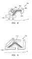
FIG. 6 is a third embodiment of a seal assembly; -
FIG. 7 is a fourth embodiment of a seal assembly; -
FIG. 8 is a fifth embodiment of a seal assembly; and -
FIG. 9 is a sixth embodiment of a seal assembly. -
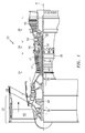
FIG. 1 schematically illustrates agas turbine engine 20 disclosed as a two-spool turbo fan that generally incorporates afan section 22, acompressor section 24, acombustor section 26 and aturbine section 28. Thefan section 22 drives air along a bypass flowpath while thecompressor section 24 drives air along a core flowpath for compression and communication into thecombustor section 26 then expansion through theturbine section 28. Although depicted as a turbofan in the disclosed non-limiting embodiment, it should be understood that the concepts described herein are not limited to use with turbofans as the teachings may be applied to other types of turbine engine architecture such as turbojets, turboshafts, three-spool turbofans, land-based turbine engines, and others. - The
engine 20 generally includes alow spool 30 and ahigh spool 32 mounted for rotation about an engine axis A viaseveral bearing structures 38 and relative to astatic engine case 36. Thelow spool 30 generally includes aninner shaft 40 that interconnects afan 42 of thefan section 22, a low pressure compressor 44 ("LPC") of thecompressor section 24 and a low pressure turbine 46 ("LPT") of theturbine section 28. Theinner shaft 40 drives thefan 42 directly, or, through a gearedarchitecture 48 to drive thefan 42 at a lower speed than thelow spool 30. An exemplary reduction transmission may be an epicyclic transmission, namely a planetary or star gear system. - The
high spool 32 includes anouter shaft 50 that interconnects a high pressure compressor 52 ("HPC") of thecompressor section 24 and a high pressure turbine 54 ("HPT") of theturbine section 28. Acombustor 56 of thecombustor section 26 is arranged between the HPC 52 and the HPT 54. Theinner shaft 40 and theouter shaft 50 are concentric and rotate about the engine axis A. Core airflow is compressed by theLPC 44 then the HPC 52, mixed with the fuel and burned in thecombustor 56, then expanded over the HPT 54 and theLPT 46. TheLPT 46 and HPT 54 rotationally drive the respectivelow spool 30 andhigh spool 32 in response to the expansion. - In one non-limiting example, the
gas turbine engine 20 is a high-bypass geared aircraft engine. In a further example, thegas turbine engine 20 bypass ratio is greater than about six (6:1). The gearedarchitecture 48 can include an epicyclic gear train, such as a planetary gear system or other gear system. The example epicyclic gear train has a gear reduction ratio of greater than about 2.3:1, and in another example is greater than about 2.5:1. The geared turbofan enables operation of thelow spool 30 at higher speeds that can increase the operational efficiency of theLPC 44 andLPT 46 and render increased pressure in a fewer number of stages. - A pressure ratio associated with the
LPT 46 is pressure measured prior to the inlet of theLPT 46 as related to the pressure at the outlet of theLPT 46 prior to an exhaust nozzle of thegas turbine engine 20. In one non-limiting example, the bypass ratio of thegas turbine engine 20 is greater than about ten (10:1); the fan diameter is significantly larger than theLPC 44; and theLPT 46 has a pressure ratio that is greater than about five (5:1). It should be understood; however, that the above parameters are only exemplary of one example of a geared architecture engine and that the present disclosure is applicable to other gas turbine engines including direct drive turbofans. - In one non-limiting example, a significant amount of thrust is provided by the bypass flow path 'B' due to the high bypass ratio. The
fan section 22 of thegas turbine engine 20 is designed for a particular flight condition - typically cruise at about 0.8 Mach and about 35,000 feet (10,668 meters). This flight condition, with thegas turbine engine 20 at its best fuel consumption, is also known as Thrust Specific Fuel consumption (TSFC). TSFC is an industry standard parameter of fuel consumption per unit of thrust. - Fan Pressure Ratio is the pressure ratio across a blade of the
fan section 22 without the use of a fan exit guide vane system. The low Fan Pressure Ratio according to one, non-limiting, example of thegas turbine engine 20 is less than 1.45:1. Low Corrected Fan Tip Speed is the actual fan tip speed divided by an industry standard temperature correction of (T/518.7)0.5, where "T" represents the ambient temperature in degrees Rankine. The Low Corrected Fan Tip Speed according to one non-limiting example of thegas turbine engine 20 is less than about 1150 feet per second (351 meters per second). - Referring to
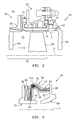
FIG. 2 , theturbine section 28 may include a plurality ofstages 58 each having a forward, stationary,vane assembly 60 and an axiallyaft blade assembly 62 generally in the core flowpath. As illustrated, onecomplete stage 58 is shown along with avane assembly 60 of an adjacent and downstream stage. Eachvane assembly 60 has a plurality ofvanes 64 spaced circumferentially from one-another and radially extending between, and supported by, circumferentially extending inner and outer structures or shroud rings 66 disposed concentrically to engine axis A (only the outer shroud ring shown). The shroud rings 66 along with thevanes 64 may be formed as one unitary piece, or eachvane 64 or any number of vanes may be formed to individual, circumferential, segments of theshroud ring 66, that when assembled, form a complete ring. - Each
blade assembly 62 has a plurality ofrotating blades 68 and a stationary structure or blade outer air seal (BOAS)ring 70 that may be segmented circumferentially. Theblades 68 are spaced circumferentially from one-another and project radially outward from, and engaged to, a rotor (not shown) centered to the engine axis A and to adistal tip 72 of theblade 68. Thedistal tip 72 is in close association with theBOAS ring 70 to minimize or eliminate any flow leakage or bypass of hot core engine air flowing (i.e. between thering 70 and tip 72) through anengine core flowpath 74 generally defined radially between the inner and outer shroud rings 66 of thevane assemblies 60 and theBOAS ring 70 and blade platforms of the blades 68 (not shown). - Referring to
FIGS. 2 and 3 , at least one annular, brush seal,assembly 76 may be located between theouter shroud ring 66 of thevane assembly 60 and theBOAS ring 70 of theblade assembly 62 for the prevention of unwanted cooling air leakage from a secondary cooling flowpath 78 (generally defined radially between theengine case 36 and therings 66, 70) and into thehot core flowpath 74. Traditionally, such sealing is accomplished through W-shaped seals, and/or seals without bristle-packs, typically made of hardened metal alloys and very thin sheet stock that are susceptible to cracking and wear. - The
brush seal assembly 76 may generally include afirst surface 80 carried by the structure orBOAS ring 70, asecond surface 82 carried by the structure orshroud ring 66, a dual-endedbrush seal 84 in sealing relationship between thesurfaces resilient member 86 located between athird surface 88 of theBOAS ring 70 and the dual-endedbrush seal 84 for biasing theseal 84 against thesecond surface 82. It is further contemplated and understood that the component relationships may be interchanged. For example, theresilient member 86 may be located between a third surface of the ring 66 (not shown) and the dual-endedbrush seal 84. Furthermore, application of thebrush seal assembly 76 may not be limited to sealing between ashroud ring 66 and aBOAS ring 70 but any stationary structures that may be part of a gas turbine engine or otherwise. - The
first surface 80 of theBOAS ring 70, in the present example, is generally annular and faces substantially in an axial direction. Thesecond surface 82 of theouter shroud ring 66 may be circumferentially continuous and faces radially outward with respect to axis A, and thethird surface 88 of theBOAS ring 70 may be annular, substantially normal to thefirst surface 80, and opposed to thesecond surface 82. - The dual-ended
brush seal 84 is annular, may be generally L-shaped in cross section, and extends circumferentially with respect toaxis A. Seal 84 includes a bristle-pack 90 that is compressed, or otherwise engaged between twometallic sheets pack 90 may be continuous, and thus spans between opposite first and second ends 96, 98 each projecting outward from thesheets first end 96 may be in sealing contact with thefirst surface 80 of theBOAS ring 70 and thesecond end 98 may be in sealing contact with thesecond surface 82 of theshroud ring 66. Unlike that required for more traditional W-shaped seals, either one or both of thesurfaces pack 90 may be about 0.002 inches (0.051 millimeters) in diameter with a material composition of a superalloy such as cobalt-based HAYNES 25 (AMS 5759). Other high temperature material compositions for the bristle-pack may include a nickel-based superalloy, Waspaloy (a United States registered trademark of United Technologies Corporation, Hartford, Connecticut) and a nickel-chromium based superalloy, INCO 625, depending on temperature exposure and deflection requirements of a particular application. - The radially outer and
inner sheets sheet ends pack 90 may be bent around the convolutedinner sheet 94. The annularouter sheet 92 may be slid axially over the bristle pack and a cylindrical portion of theouter sheet 92 may then be bent radially inward to conform to and/or crimp the bristles. Thesheets pack 90 may then be laser welded together forming aweld 100 at a radially outward location, and the brush ends 96, 98 cut and formed to final dimensions. One example of a cutting technique is electrical discharge machining (EDM). - Unlike more traditional brush seals, subsequent manufacturing heat treat cycle(s) of
seal 84 may not be necessary since theseal 84 may not develop hoop stresses typical of a diametrally snapped-in seals. At least theouter sheet 92 may further include a series of open ended and circumferentially spaced slots that divide an axially downstream portion of theouter sheet 92 into a plurality of axially extendingtabs 102 that may be crimped radially inward against the bristle-pack 90 during manufacture. It is further contemplated and understood that in addition to theouter sheet 92, or alternatively, theinner sheet 94 may have similar slots and tabs. - Each
sheet seal 84 is less structurally challenged than traditional brush seals, higher temperature capable and lower cost alloys can be used. - Referring to
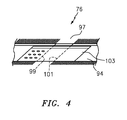
FIG. 4 , seal 84 may have at least one circumferential split orsplice 97 that maintains a pressure loaded, radial, contact regardless of relative thermal displacements. Thesplit 97 may generally be defined between two generally opposingend portions seal 84 that are substantially parallel to one-another and cut at a substantial angle. Thesplit 97 may be generally sealed by a slidingbridge 103 that spans circumferentially across thesplit 97 and limits leakage at the splice location. Thebridge 103 may generally be located radially inward of theinner sheet 94, rigidly attached to theinner sheet 94 at theend portion 99 location (e.g. resistance welded), and may further be in a sliding relationship with theinner sheet 94 at theend portion 101 location. The cross sectional contour of thebridge 103 may generally conform to the cross sectional contour of theinner sheet 94. It is further contemplated and understood that theseal 84 may not require a split. Furthermore, thebridge 103 may be located radially outward of theouter sheet 92 and thus attached to theouter sheet 92 at theend portion 99. - In operation, the
seal 84 may generally be free-floating and the pressure differential between thesecondary cooling flowpath 78 and the core flowpath 74 loads theseal 84 against the axial (i.e. cylindrical)surface 80 and the radial (i.e. annular)surface 82. As theBOAS ring 70 andshroud ring 66 move axially and radially relative to each other, the brush ends 96, 98 of the bristle-pack 90 deflect against and slide along the mating surfaces to maintain sealing. - The
resilient member 86 may be a wave spring that may be generally annular and circumferentially continuous. Themember 86 is compressed axially, with respect to axis A, between thethird surface 88 of theBOAS ring 70 and theouter sheet 92 of theseal 84. In operation, theresilient member 86 applies a relatively light axial load during assembly to ensure theseal 84 is immediately pressure-energized during engine start-up. Other than the contact of themember 86 with theseal 84, the seal may generally be free floating with respect to therings - Referring to
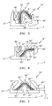
FIG. 5 , a second embodiment of the present disclosure is illustrated wherein like elements to the first embodiment have like identifying numerals except with the addition of a prime symbol. A brush seal assembly 76' of the second embodiment includes a first surface 80' carried by a BOAS ring 70', a second surface 82' carried by a shroud ring 66', a dual-ended brush seal 84' in sealing relationship between the surfaces 80', 82', and a resilient member 86' located between a third surface 88' of the BOAS ring 70' and the dual-ended brush seal 84'. Seal 84' includes a bristle-pack 90' engaged between two sheets 92', 94'. The bristle-pack 90' has projecting first and second ends 96', 98' with the first end 96' in sealing contact with the first surface 80' of the BOAS ring 70' and the second end 98' in sealing contact with the second surface 82' of the shroud ring 66'. - The seal 84' may generally be bent at an acute angle with the first end 96' projecting in a radially inward direction that is substantially normal to the first surface 80' and the second end 98' projecting in both an axial and radially inward direction such that the second end 98' is generally angled with respect to the second surface 82'. As previously described, the second end 98' may be cut and formed to final dimensions enabling a sealing contact upon the second surface 82'. The seal 84' is generally compact, easy to manufacture, and has resilient characteristics.
- Referring to
FIG. 6 , a third embodiment of the present disclosure is illustrated wherein like elements to the first embodiment have like identifying numerals except with the addition of a double prime symbol. Abrush seal assembly 76" of the third embodiment includes afirst surface 80" carried by aBOAS ring 70", asecond surface 82" carried by ashroud ring 66", a dual-endedbrush seal 84" in sealing relationship between thesurfaces 80", 82", and aresilient member 86" located between athird surface 88" of theBOAS ring 70" and the dual-endedbrush seal 84".Seal 84" includes a bristle-pack 90" engaged between radially outer andinner sheets 92", 94". The bristle-pack 90" has projecting first and second ends 96", 98" with thefirst end 96" in sealing contact with thefirst surface 80" of theBOAS ring 70" and thesecond end 98" in sealing contact with thesecond surface 82" of theshroud ring 66". - The
seal 84" may generally be bent at an obtuse angle with thefirst end 96" projecting in both an axial and radially inward direction such that thefirst end 96" is generally angled with respect to thefirst surface 80" and thesecond end 98" projects in an axial direction that is substantially normal to thesecond surface 82". Theouter sheet 92" has an axiallyupstream portion 104, adownstream portion 106, a generally outward face 108 and anopposite face 110. Theupstream portion 104 is generally bent and projects radially outward from thedownstream portion 106, away from (i.e. spaced from) the bristle-pack 90", and is in biased contact with theresilient member 86". More specifically,face 110, which is carried by bothportions bristle pack 90" and theresilient member 86". Theseal 84" may enable positioning at more optimum sealing locations in the engine. - Referring to
FIG. 7 , a fourth embodiment of the present disclosure is illustrated wherein like elements to the first embodiment have like identifying numerals except with the addition of a triple prime symbol. Abrush seal assembly 76"' of the fourth embodiment includes afirst surface 80"' carried by aBOAS ring 70"', asecond surface 82"' carried by ashroud ring 66"', and a dual-ended brush seal 84'" in sealing relationship between thesurfaces 80"', 82"'.Seal 84"' includes a bristle-pack 90"' engaged between radially outer andinner sheets 92"', 94"'. The bristle-pack 90"' has projecting first and second ends 96"', 98"' with thefirst end 96"' in sealing contact with thefirst surface 80"' of theBOAS ring 70"' and thesecond end 98"' in sealing contact with thesecond surface 82"' of theshroud ring 66"'. - The first and
second surfaces 80"', 82"' are both substantially cylindrical and face radially outward. The seal 84'" may generally be bent at about a right angle with thefirst end 96"' projecting in both an axial upstream and radially inward direction such that thefirst end 96"' is generally angled with respect to thefirst surface 80"'. Similarly, thesecond end 98"' projects in in both an axial downstream and radially inward direction with thesecond end 98"' angled with respect to thesecond surface 82"'. Because of the circular/annular orientation of therings 66"', 70"' and seal 84"', the seal may generally be free floating with respect to the rings. Advantages of seal 84'" include, but are not limited to, sealing against two radial surfaces and a low radial profile. - The
inner sheet 94"' of theseal 84"' may have opposite edges positioned radially outward from the respective sealing surfaces 80"', 82"' by a predetermined distance orgap 112. Thegap 112 may be minimized to further reduce air leakage during normal engine operation and as the bristles wear. - Referring to
FIG. 8 , a fifth embodiment of the present disclosure is illustrated that is similar to the third embodiment ofFIG. 5 , and wherein like elements to the third embodiment have like identifying numerals except with the new suffix "A". Abrush seal assembly 76A of the fifth embodiment includes aBOAS ring 70A that generally holds and positions aresilient member 86A to exert a biasing force against a dual endedbrush seal 84A. This biasing force is generally in an angled direction with respect to the engine axis A, and is in both a radially inward direction and an axial direction. Themember 86A may be a wave spring. The biasing force direction (i.e. angled) enables a compact design of theassembly 76A and ensures the first and second ends 96A, 98A remain in sealing contact with the respective first andsecond surfaces - Referring to
FIG. 9 , a sixth embodiment of the present disclosure is illustrated that is similar to the fourth embodiment ofFIG. 6 , and wherein like elements to the fourth embodiment have like identifying numerals except with the new suffix "B". Abrush seal assembly 76B of the sixth embodiment includes aBOAS ring 70B having a cantileveredportion 114 that extends axially and radially over theouter sheet 92B to protect and generally hold the brush seal 84B in place. Thesheet 92B may further contact the cantileveredportion 114 thereby biasing the bristles against the respective sealing surfaces. - It is understood that relative positional terms such as "forward," "aft," "upper," "lower," "above," "below," and the like are with reference to the normal operational attitude and should not be considered otherwise limiting. It is also understood that like reference numerals identify corresponding or similar elements throughout the several drawings. It should be understood that although a particular component arrangement is disclosed in the illustrated embodiment, other arrangements will also benefit. Although particular step sequences may be shown, described, and claimed, it is understood that steps may be performed in any order, separated or combined unless otherwise indicated and will still benefit from the present disclosure.
- The foregoing description is exemplary rather than defined by the limitations described. Various non-limiting embodiments are disclosed; however, one of ordinary skill in the art would recognize that various modifications and variations in light of the above teachings will fall within the scope of the appended claims. It is therefore understood that within the scope of the appended claims, the disclosure may be practiced other than as specifically described. For this reason, the appended claims should be studied to determine true scope and content.
Claims (15)
- A dual-ended brush seal assembly comprising:a first structure (70) including a first surface (80);a second structure (66) including a second surface (82); anda brush seal (84) including a bent bristle-pack (90) having a first end (96) projecting in a first direction and in sealing contact with the first surface (80) and an opposite second end (98) projecting in a second direction and in sealing contact with the second surface (82), wherein the first and second directions traverse one-another.
- The dual-ended brush seal assembly set forth in claim 1, wherein the first structure (70) is a BOAS ring and the second structure (66) is a vane shroud ring.
- The dual-ended brush seal assembly set forth in claim 1 or 2, wherein the brush seal (84) is generally annular.
- The dual-ended brush seal assembly set forth in claim 1, 2 or 3, wherein the first surface (80) is orientated substantially normal to the second surface (82).
- The dual-ended brush seal assembly set forth in any preceding claim, wherein the brush seal (84) is free-floating.
- The dual-ended brush seal assembly set forth in any preceding claim, wherein the brush seal (84) includes first and second sheets (92,94) each having an arcuate cross section with the bristle-pack (90) extending therebetween and at least one of the first and second sheets (92,94) are made of a non-hardenable nickel-based alloy;
wherein optionally the non-hardenable nickel-based alloy is at least one of INCONEL 625 (AMS 5599), HASTALOY X (AMS 5536) and HAYNES 188 (AMS 5891). - The dual-ended brush seal assembly set forth in any of claims 1-5, wherein the brush seal (84) includes first and second sheets (92,94) each having an arcuate cross section with the bristle-pack (91) extending therebetween;
wherein optionally the brush seal (84) includes a weld (100) that fuses the bristle-pack (90) and at least one of the first and second sheets (92,94) together. - The dual-ended brush seal assembly set forth in any preceding claim, wherein the first and second structures (70,66) are generally annular and concentric to one-another with the first surface (80) spanning substantially axially and the second surface (82) spanning substantially radially.
- The dual-ended brush seal assembly set forth in claim 7 or 8 further comprising:at least one resilient member (86) disposed axially between a third surface (88) of the first structure (70) that opposes the second surface (82), and the brush seal (84) for biasing the second end (98) against the second surface (82);
wherein optionally the resilient member (86) is an annular wave-spring. - A dual-ended brush seal comprising:an annular bristle-pack (90) having a sealing first end (96) and an opposite sealing second end (98); andfirst and second sheets (92,94) each having an arcuate cross section with the bristle-pack (90) extending therebetween.
- The dual-ended brush seal set forth in claim 10 further comprising:a weld (100) that fuses the bristle-pack (90) and at least one of the first and second sheets (92,94) together.
- The dual-ended brush seal set forth in claim 10 or 11, wherein the first end (96) is constructed and arranged to seal in a direction that generally traverses a sealing direction of the second end (98); and/or
wherein the first and second ends (96,98) are constructed and arranged to seal substantially radially; and/or
wherein the second sheet (94) includes a plurality of tabs (102) for crimping against the bristle-pack (90). - A method of manufacturing a dual-ended brush seal comprising the steps of:bending a bristle-pack (90) about a bent first sheet (92);sliding a second sheet (94) over the bristle-pack (90) such that the bristle-pack (90) is located between the first and second sheets (92,94) and opposite distal ends (96,98) of the bristle pack (90) project outward from the first and second sheets (92,94); andcrimping the second sheet (94) toward the first sheet (92) and against the bristle pack (90).
- The method of manufacturing set forth in claim 13 comprising the further step of:welding at least one of the first and second sheets (92,94) to the bristle-pack (90).
- The method of manufacturing set forth in claim 13 or 14 comprising the further step of:cutting the distal ends (96,98) into prescribed final dimensions.
Priority Applications (1)
| Application Number | Priority Date | Filing Date | Title |
|---|---|---|---|
| EP18191467.2A EP3431835B8 (en) | 2014-08-28 | 2015-08-27 | Dual-ended brush seal assembly and method of manufacture |
Applications Claiming Priority (1)
| Application Number | Priority Date | Filing Date | Title |
|---|---|---|---|
| US201462043117P | 2014-08-28 | 2014-08-28 |
Related Child Applications (2)
| Application Number | Title | Priority Date | Filing Date |
|---|---|---|---|
| EP18191467.2A Division EP3431835B8 (en) | 2014-08-28 | 2015-08-27 | Dual-ended brush seal assembly and method of manufacture |
| EP18191467.2A Division-Into EP3431835B8 (en) | 2014-08-28 | 2015-08-27 | Dual-ended brush seal assembly and method of manufacture |
Publications (2)
| Publication Number | Publication Date |
|---|---|
| EP2990699A1 true EP2990699A1 (en) | 2016-03-02 |
| EP2990699B1 EP2990699B1 (en) | 2018-10-17 |
Family
ID=54012068
Family Applications (2)
| Application Number | Title | Priority Date | Filing Date |
|---|---|---|---|
| EP15182770.6A Active EP2990699B1 (en) | 2014-08-28 | 2015-08-27 | Dual-ended brush seal assembly and method of manufacture |
| EP18191467.2A Active EP3431835B8 (en) | 2014-08-28 | 2015-08-27 | Dual-ended brush seal assembly and method of manufacture |
Family Applications After (1)
| Application Number | Title | Priority Date | Filing Date |
|---|---|---|---|
| EP18191467.2A Active EP3431835B8 (en) | 2014-08-28 | 2015-08-27 | Dual-ended brush seal assembly and method of manufacture |
Country Status (2)
| Country | Link |
|---|---|
| US (2) | US10400896B2 (en) |
| EP (2) | EP2990699B1 (en) |
Cited By (6)
| Publication number | Priority date | Publication date | Assignee | Title |
|---|---|---|---|---|
| EP3228828A1 (en) * | 2016-04-07 | 2017-10-11 | United Technologies Corporation | Integrated brush seals |
| EP3431715A1 (en) * | 2017-07-19 | 2019-01-23 | United Technologies Corporation | Compact brush seal |
| EP3550183A1 (en) * | 2018-04-05 | 2019-10-09 | United Technologies Corporation | Multi-plane brush seal |
| EP3608512A1 (en) * | 2018-07-31 | 2020-02-12 | United Technologies Corporation | Gas turbine engine with sealing surface for blade outer air seal |
| EP3670845A1 (en) * | 2018-12-21 | 2020-06-24 | MTU Aero Engines GmbH | Static seal assembly and turbomachine |
| EP3819527A1 (en) * | 2019-11-11 | 2021-05-12 | Raytheon Technologies Corporation | Double angled brush seal |
Families Citing this family (17)
| Publication number | Priority date | Publication date | Assignee | Title |
|---|---|---|---|---|
| US9863538B2 (en) * | 2015-04-27 | 2018-01-09 | United Technologies Corporation | Gas turbine engine brush seal with supported tip |
| DE102015217078A1 (en) * | 2015-09-07 | 2017-03-09 | MTU Aero Engines AG | Device for limiting a flow channel of a turbomachine |
| US10352183B2 (en) | 2016-04-25 | 2019-07-16 | United Technologies Corporation | High temperature seal and method |
| US10519794B2 (en) * | 2016-07-12 | 2019-12-31 | General Electric Company | Sealing system for sealing against a non-cylindrical surface |
| US10962117B2 (en) * | 2017-12-18 | 2021-03-30 | Raytheon Technologies Corporation | Brush seal with spring-loaded backing plate |
| US11035470B2 (en) * | 2018-04-05 | 2021-06-15 | Raytheon Technologies Corporation | Multi-plane brush seal |
| US11085316B2 (en) * | 2018-08-22 | 2021-08-10 | Raytheon Technologies Corporation | Blade outer air seal formed of laminate and having radial support hooks |
| US10787923B2 (en) * | 2018-08-27 | 2020-09-29 | Raytheon Technologies Corporation | Axially preloaded seal |
| US10822964B2 (en) | 2018-11-13 | 2020-11-03 | Raytheon Technologies Corporation | Blade outer air seal with non-linear response |
| US10934941B2 (en) | 2018-11-19 | 2021-03-02 | Raytheon Technologies Corporation | Air seal interface with AFT engagement features and active clearance control for a gas turbine engine |
| US10920618B2 (en) * | 2018-11-19 | 2021-02-16 | Raytheon Technologies Corporation | Air seal interface with forward engagement features and active clearance control for a gas turbine engine |
| US10989059B2 (en) * | 2019-04-10 | 2021-04-27 | Raytheon Technologies Corporation | CMC BOAS arrangement |
| US11428323B2 (en) * | 2019-04-16 | 2022-08-30 | Raytheon Technologies Corporation | Floating brush seal assembly |
| US11624441B2 (en) | 2021-04-30 | 2023-04-11 | Raytheon Technologies Corporation | Reinforced brush seal assembly |
| US11619138B2 (en) * | 2021-04-30 | 2023-04-04 | Raytheon Technologies Corporation | Double brush seal assembly |
| US20230265767A1 (en) * | 2022-02-22 | 2023-08-24 | General Electric Company | Seal for a rotor |
| US11879340B1 (en) * | 2022-09-30 | 2024-01-23 | Rtx Corporation | Angled brush seal and gas turbine engine component combination |
Citations (3)
| Publication number | Priority date | Publication date | Assignee | Title |
|---|---|---|---|---|
| EP1013887A1 (en) * | 1998-12-23 | 2000-06-28 | United Technologies Corporation | A brush seal for gas turbine engines |
| US20040100033A1 (en) * | 2002-11-27 | 2004-05-27 | Wei Tong | Sealing apparatus for electrical generator ventilation system |
| US20100327535A1 (en) * | 2004-03-16 | 2010-12-30 | General Electric Company | Fiber seal for ceramic matrix composite components |
Family Cites Families (26)
| Publication number | Priority date | Publication date | Assignee | Title |
|---|---|---|---|---|
| US5114159A (en) * | 1991-08-05 | 1992-05-19 | United Technologies Corporation | Brush seal and damper |
| DE19618475B4 (en) * | 1996-05-08 | 2005-10-20 | Mtu Aero Engines Gmbh | brush seal |
| DE59710884D1 (en) * | 1996-10-02 | 2003-11-27 | Mtu Aero Engines Gmbh | brush seal |
| US6406027B1 (en) * | 1999-07-22 | 2002-06-18 | General Electric Company | Brush seal and machine having a brush seal |
| DE19962316C2 (en) * | 1999-12-23 | 2002-07-18 | Mtu Aero Engines Gmbh | brush seal |
| GB9930620D0 (en) * | 1999-12-24 | 2000-02-16 | Cross Mfg Co | Brush seals |
| US6711858B1 (en) * | 2000-09-07 | 2004-03-30 | Ultrafab, Inc. | Pile weatherstripping |
| US6502825B2 (en) * | 2000-12-26 | 2003-01-07 | General Electric Company | Pressure activated cloth seal |
| US20100007093A1 (en) * | 2001-02-23 | 2010-01-14 | Grondahl Clayton M | Seal Assembly and Rotary Machine Containing Such Seal |
| GB0203492D0 (en) * | 2002-02-14 | 2002-04-03 | Rolls Royce Plc | Brush seal |
| FR2865012B1 (en) * | 2004-01-12 | 2006-03-17 | Snecma Moteurs | SEALING DEVICE FOR TURBOMACHINE HIGH-PRESSURE TURBINE |
| US20080128996A1 (en) * | 2004-03-16 | 2008-06-05 | General Electric Company | Silicon carbide fiber seal for ceramic matrix composite components |
| ES2583083T3 (en) * | 2004-04-27 | 2016-09-19 | Tsuchiya Tsco Co., Ltd. | Two-part brush strip that contains two base strips connected by brush fibers |
| DE102006049634A1 (en) * | 2006-10-20 | 2008-04-24 | Mtu Aero Engines Gmbh | sealing arrangement |
| US8568091B2 (en) * | 2008-02-18 | 2013-10-29 | United Technologies Corporation | Gas turbine engine systems and methods involving blade outer air seals |
| US8474827B2 (en) * | 2010-06-11 | 2013-07-02 | Cmg Tech, Llc | Film riding pressure actuated leaf seal assembly |
| US9121297B2 (en) * | 2011-03-28 | 2015-09-01 | General Electric Company | Rotating brush seal |
| US20130170979A1 (en) * | 2012-01-04 | 2013-07-04 | General Electric Company | Double ended brush seal assembly for a compressor |
| US10138742B2 (en) * | 2012-12-29 | 2018-11-27 | United Technologies Corporation | Multi-ply finger seal |
| WO2014123190A1 (en) * | 2013-02-06 | 2014-08-14 | イーグル工業株式会社 | Brush seal device |
| FR3003301B1 (en) * | 2013-03-14 | 2018-01-05 | Safran Helicopter Engines | TURBINE RING FOR TURBOMACHINE |
| WO2015005972A1 (en) * | 2013-07-11 | 2015-01-15 | United Technologies Corporation | Stationary non-rotating brush seals |
| US9322287B2 (en) * | 2014-06-03 | 2016-04-26 | General Electric Company | Brush seal for turbine |
| US10370993B2 (en) * | 2014-10-24 | 2019-08-06 | United Technologies Corporation | Sliding seal |
| US9957827B2 (en) * | 2014-10-24 | 2018-05-01 | United Technologies Corporation | Conformal seal |
| EP3073058B1 (en) * | 2015-03-27 | 2020-06-10 | Ansaldo Energia Switzerland AG | Sealing arrangements in gas turbines |
-
2015
- 2015-08-26 US US14/836,302 patent/US10400896B2/en active Active
- 2015-08-27 EP EP15182770.6A patent/EP2990699B1/en active Active
- 2015-08-27 EP EP18191467.2A patent/EP3431835B8/en active Active
-
2019
- 2019-07-18 US US16/515,548 patent/US10935139B2/en active Active
Patent Citations (3)
| Publication number | Priority date | Publication date | Assignee | Title |
|---|---|---|---|---|
| EP1013887A1 (en) * | 1998-12-23 | 2000-06-28 | United Technologies Corporation | A brush seal for gas turbine engines |
| US20040100033A1 (en) * | 2002-11-27 | 2004-05-27 | Wei Tong | Sealing apparatus for electrical generator ventilation system |
| US20100327535A1 (en) * | 2004-03-16 | 2010-12-30 | General Electric Company | Fiber seal for ceramic matrix composite components |
Cited By (11)
| Publication number | Priority date | Publication date | Assignee | Title |
|---|---|---|---|---|
| EP3228828A1 (en) * | 2016-04-07 | 2017-10-11 | United Technologies Corporation | Integrated brush seals |
| EP3431715A1 (en) * | 2017-07-19 | 2019-01-23 | United Technologies Corporation | Compact brush seal |
| US11486497B2 (en) | 2017-07-19 | 2022-11-01 | Raytheon Technologies Corporation | Compact brush seal |
| EP3550183A1 (en) * | 2018-04-05 | 2019-10-09 | United Technologies Corporation | Multi-plane brush seal |
| EP3608512A1 (en) * | 2018-07-31 | 2020-02-12 | United Technologies Corporation | Gas turbine engine with sealing surface for blade outer air seal |
| US10633995B2 (en) | 2018-07-31 | 2020-04-28 | United Technologies Corporation | Sealing surface for ceramic matrix composite blade outer air seal |
| US11371376B2 (en) | 2018-07-31 | 2022-06-28 | Raytheon Technologies Corporation | Sealing surface for ceramic matrix composite blade outer air seal |
| EP3670845A1 (en) * | 2018-12-21 | 2020-06-24 | MTU Aero Engines GmbH | Static seal assembly and turbomachine |
| US11208908B2 (en) | 2018-12-21 | 2021-12-28 | MTU Aero Engines AG | Static seal arrangement and turbomachine |
| EP3819527A1 (en) * | 2019-11-11 | 2021-05-12 | Raytheon Technologies Corporation | Double angled brush seal |
| US11261971B2 (en) | 2019-11-11 | 2022-03-01 | Raytheon Technologies Corporation | Double angled brush seal |
Also Published As
| Publication number | Publication date |
|---|---|
| US10935139B2 (en) | 2021-03-02 |
| US20200103036A1 (en) | 2020-04-02 |
| EP3431835B8 (en) | 2021-04-07 |
| EP3431835A3 (en) | 2019-10-02 |
| EP3431835A1 (en) | 2019-01-23 |
| EP3431835B1 (en) | 2021-02-17 |
| US10400896B2 (en) | 2019-09-03 |
| EP2990699B1 (en) | 2018-10-17 |
| US20160061330A1 (en) | 2016-03-03 |
Similar Documents
| Publication | Publication Date | Title |
|---|---|---|
| US10935139B2 (en) | Dual-ended brush seal assembly and method of manufacture | |
| EP2949874B1 (en) | Dual walled seal assembly | |
| US9957827B2 (en) | Conformal seal | |
| US10088049B2 (en) | Thermally protected seal assembly | |
| EP2984296B1 (en) | Blade outer air seal with secondary air sealing | |
| US10487943B2 (en) | Multi-ply seal ring | |
| EP3249170B1 (en) | Seal assembly with seal rings for gas turbine engines | |
| US10094244B2 (en) | Ceramic matrix composite ring shroud retention methods-wiggle strip spring seal | |
| US9708922B1 (en) | Seal ring for gas turbine engines | |
| EP3085901A1 (en) | Seal | |
| US11073034B2 (en) | Seal assembly for sealing an axial gap between components | |
| EP3147462A1 (en) | Gas turbine engine sealing assembly with a seal having a shield member and a spring member made of different materials and corresponding gas turbine engine | |
| US10273821B2 (en) | Advanced stationary sealing cooled cross-section for axial retention of ceramic matrix composite shrouds | |
| EP3543469B1 (en) | Blade outer air seal assembly with feather seal | |
| US10280777B2 (en) | System and method including a circumferential seal assembly to facilitate sealing in a turbine | |
| US11608752B2 (en) | Sealing apparatus for an axial flow turbomachine | |
| US10036269B2 (en) | Leaf seal reach over spring with retention mechanism | |
| US11300209B2 (en) | Wire mesh brush seal windage cover | |
| US20220268166A1 (en) | Non-contacting seal assembly with internal coating |
Legal Events
| Date | Code | Title | Description |
|---|---|---|---|
| PUAI | Public reference made under article 153(3) epc to a published international application that has entered the european phase |
Free format text: ORIGINAL CODE: 0009012 |
|
| AK | Designated contracting states |
Kind code of ref document: A1 Designated state(s): AL AT BE BG CH CY CZ DE DK EE ES FI FR GB GR HR HU IE IS IT LI LT LU LV MC MK MT NL NO PL PT RO RS SE SI SK SM TR |
|
| AX | Request for extension of the european patent |
Extension state: BA ME |
|
| 17P | Request for examination filed |
Effective date: 20160901 |
|
| RBV | Designated contracting states (corrected) |
Designated state(s): AL AT BE BG CH CY CZ DE DK EE ES FI FR GB GR HR HU IE IS IT LI LT LU LV MC MK MT NL NO PL PT RO RS SE SI SK SM TR |
|
| RAP1 | Party data changed (applicant data changed or rights of an application transferred) |
Owner name: UNITED TECHNOLOGIES CORPORATION |
|
| STAA | Information on the status of an ep patent application or granted ep patent |
Free format text: STATUS: EXAMINATION IS IN PROGRESS |
|
| 17Q | First examination report despatched |
Effective date: 20170522 |
|
| GRAP | Despatch of communication of intention to grant a patent |
Free format text: ORIGINAL CODE: EPIDOSNIGR1 |
|
| STAA | Information on the status of an ep patent application or granted ep patent |
Free format text: STATUS: GRANT OF PATENT IS INTENDED |
|
| INTG | Intention to grant announced |
Effective date: 20180503 |
|
| GRAS | Grant fee paid |
Free format text: ORIGINAL CODE: EPIDOSNIGR3 |
|
| GRAA | (expected) grant |
Free format text: ORIGINAL CODE: 0009210 |
|
| STAA | Information on the status of an ep patent application or granted ep patent |
Free format text: STATUS: THE PATENT HAS BEEN GRANTED |
|
| AK | Designated contracting states |
Kind code of ref document: B1 Designated state(s): AL AT BE BG CH CY CZ DE DK EE ES FI FR GB GR HR HU IE IS IT LI LT LU LV MC MK MT NL NO PL PT RO RS SE SI SK SM TR |
|
| REG | Reference to a national code |
Ref country code: GB Ref legal event code: FG4D |
|
| REG | Reference to a national code |
Ref country code: CH Ref legal event code: EP |
|
| REG | Reference to a national code |
Ref country code: IE Ref legal event code: FG4D |
|
| REG | Reference to a national code |
Ref country code: DE Ref legal event code: R096 Ref document number: 602015018192 Country of ref document: DE Ref country code: AT Ref legal event code: REF Ref document number: 1054438 Country of ref document: AT Kind code of ref document: T Effective date: 20181115 |
|
| REG | Reference to a national code |
Ref country code: NL Ref legal event code: MP Effective date: 20181017 |
|
| REG | Reference to a national code |
Ref country code: LT Ref legal event code: MG4D |
|
| REG | Reference to a national code |
Ref country code: AT Ref legal event code: MK05 Ref document number: 1054438 Country of ref document: AT Kind code of ref document: T Effective date: 20181017 |
|
| PG25 | Lapsed in a contracting state [announced via postgrant information from national office to epo] |
Ref country code: NL Free format text: LAPSE BECAUSE OF FAILURE TO SUBMIT A TRANSLATION OF THE DESCRIPTION OR TO PAY THE FEE WITHIN THE PRESCRIBED TIME-LIMIT Effective date: 20181017 |
|
| PG25 | Lapsed in a contracting state [announced via postgrant information from national office to epo] |
Ref country code: LV Free format text: LAPSE BECAUSE OF FAILURE TO SUBMIT A TRANSLATION OF THE DESCRIPTION OR TO PAY THE FEE WITHIN THE PRESCRIBED TIME-LIMIT Effective date: 20181017 Ref country code: AT Free format text: LAPSE BECAUSE OF FAILURE TO SUBMIT A TRANSLATION OF THE DESCRIPTION OR TO PAY THE FEE WITHIN THE PRESCRIBED TIME-LIMIT Effective date: 20181017 Ref country code: ES Free format text: LAPSE BECAUSE OF FAILURE TO SUBMIT A TRANSLATION OF THE DESCRIPTION OR TO PAY THE FEE WITHIN THE PRESCRIBED TIME-LIMIT Effective date: 20181017 Ref country code: HR Free format text: LAPSE BECAUSE OF FAILURE TO SUBMIT A TRANSLATION OF THE DESCRIPTION OR TO PAY THE FEE WITHIN THE PRESCRIBED TIME-LIMIT Effective date: 20181017 Ref country code: PL Free format text: LAPSE BECAUSE OF FAILURE TO SUBMIT A TRANSLATION OF THE DESCRIPTION OR TO PAY THE FEE WITHIN THE PRESCRIBED TIME-LIMIT Effective date: 20181017 Ref country code: LT Free format text: LAPSE BECAUSE OF FAILURE TO SUBMIT A TRANSLATION OF THE DESCRIPTION OR TO PAY THE FEE WITHIN THE PRESCRIBED TIME-LIMIT Effective date: 20181017 Ref country code: IS Free format text: LAPSE BECAUSE OF FAILURE TO SUBMIT A TRANSLATION OF THE DESCRIPTION OR TO PAY THE FEE WITHIN THE PRESCRIBED TIME-LIMIT Effective date: 20190217 Ref country code: NO Free format text: LAPSE BECAUSE OF FAILURE TO SUBMIT A TRANSLATION OF THE DESCRIPTION OR TO PAY THE FEE WITHIN THE PRESCRIBED TIME-LIMIT Effective date: 20190117 Ref country code: BG Free format text: LAPSE BECAUSE OF FAILURE TO SUBMIT A TRANSLATION OF THE DESCRIPTION OR TO PAY THE FEE WITHIN THE PRESCRIBED TIME-LIMIT Effective date: 20190117 Ref country code: FI Free format text: LAPSE BECAUSE OF FAILURE TO SUBMIT A TRANSLATION OF THE DESCRIPTION OR TO PAY THE FEE WITHIN THE PRESCRIBED TIME-LIMIT Effective date: 20181017 |
|
| PG25 | Lapsed in a contracting state [announced via postgrant information from national office to epo] |
Ref country code: GR Free format text: LAPSE BECAUSE OF FAILURE TO SUBMIT A TRANSLATION OF THE DESCRIPTION OR TO PAY THE FEE WITHIN THE PRESCRIBED TIME-LIMIT Effective date: 20190118 Ref country code: RS Free format text: LAPSE BECAUSE OF FAILURE TO SUBMIT A TRANSLATION OF THE DESCRIPTION OR TO PAY THE FEE WITHIN THE PRESCRIBED TIME-LIMIT Effective date: 20181017 Ref country code: SE Free format text: LAPSE BECAUSE OF FAILURE TO SUBMIT A TRANSLATION OF THE DESCRIPTION OR TO PAY THE FEE WITHIN THE PRESCRIBED TIME-LIMIT Effective date: 20181017 Ref country code: AL Free format text: LAPSE BECAUSE OF FAILURE TO SUBMIT A TRANSLATION OF THE DESCRIPTION OR TO PAY THE FEE WITHIN THE PRESCRIBED TIME-LIMIT Effective date: 20181017 Ref country code: PT Free format text: LAPSE BECAUSE OF FAILURE TO SUBMIT A TRANSLATION OF THE DESCRIPTION OR TO PAY THE FEE WITHIN THE PRESCRIBED TIME-LIMIT Effective date: 20190217 |
|
| REG | Reference to a national code |
Ref country code: DE Ref legal event code: R097 Ref document number: 602015018192 Country of ref document: DE |
|
| PG25 | Lapsed in a contracting state [announced via postgrant information from national office to epo] |
Ref country code: DK Free format text: LAPSE BECAUSE OF FAILURE TO SUBMIT A TRANSLATION OF THE DESCRIPTION OR TO PAY THE FEE WITHIN THE PRESCRIBED TIME-LIMIT Effective date: 20181017 Ref country code: CZ Free format text: LAPSE BECAUSE OF FAILURE TO SUBMIT A TRANSLATION OF THE DESCRIPTION OR TO PAY THE FEE WITHIN THE PRESCRIBED TIME-LIMIT Effective date: 20181017 Ref country code: IT Free format text: LAPSE BECAUSE OF FAILURE TO SUBMIT A TRANSLATION OF THE DESCRIPTION OR TO PAY THE FEE WITHIN THE PRESCRIBED TIME-LIMIT Effective date: 20181017 |
|
| PLBE | No opposition filed within time limit |
Free format text: ORIGINAL CODE: 0009261 |
|
| STAA | Information on the status of an ep patent application or granted ep patent |
Free format text: STATUS: NO OPPOSITION FILED WITHIN TIME LIMIT |
|
| PG25 | Lapsed in a contracting state [announced via postgrant information from national office to epo] |
Ref country code: RO Free format text: LAPSE BECAUSE OF FAILURE TO SUBMIT A TRANSLATION OF THE DESCRIPTION OR TO PAY THE FEE WITHIN THE PRESCRIBED TIME-LIMIT Effective date: 20181017 Ref country code: SM Free format text: LAPSE BECAUSE OF FAILURE TO SUBMIT A TRANSLATION OF THE DESCRIPTION OR TO PAY THE FEE WITHIN THE PRESCRIBED TIME-LIMIT Effective date: 20181017 Ref country code: EE Free format text: LAPSE BECAUSE OF FAILURE TO SUBMIT A TRANSLATION OF THE DESCRIPTION OR TO PAY THE FEE WITHIN THE PRESCRIBED TIME-LIMIT Effective date: 20181017 Ref country code: SK Free format text: LAPSE BECAUSE OF FAILURE TO SUBMIT A TRANSLATION OF THE DESCRIPTION OR TO PAY THE FEE WITHIN THE PRESCRIBED TIME-LIMIT Effective date: 20181017 |
|
| 26N | No opposition filed |
Effective date: 20190718 |
|
| PG25 | Lapsed in a contracting state [announced via postgrant information from national office to epo] |
Ref country code: SI Free format text: LAPSE BECAUSE OF FAILURE TO SUBMIT A TRANSLATION OF THE DESCRIPTION OR TO PAY THE FEE WITHIN THE PRESCRIBED TIME-LIMIT Effective date: 20181017 |
|
| PG25 | Lapsed in a contracting state [announced via postgrant information from national office to epo] |
Ref country code: TR Free format text: LAPSE BECAUSE OF FAILURE TO SUBMIT A TRANSLATION OF THE DESCRIPTION OR TO PAY THE FEE WITHIN THE PRESCRIBED TIME-LIMIT Effective date: 20181017 |
|
| PG25 | Lapsed in a contracting state [announced via postgrant information from national office to epo] |
Ref country code: MC Free format text: LAPSE BECAUSE OF FAILURE TO SUBMIT A TRANSLATION OF THE DESCRIPTION OR TO PAY THE FEE WITHIN THE PRESCRIBED TIME-LIMIT Effective date: 20181017 Ref country code: LI Free format text: LAPSE BECAUSE OF NON-PAYMENT OF DUE FEES Effective date: 20190831 Ref country code: LU Free format text: LAPSE BECAUSE OF NON-PAYMENT OF DUE FEES Effective date: 20190827 Ref country code: CH Free format text: LAPSE BECAUSE OF NON-PAYMENT OF DUE FEES Effective date: 20190831 |
|
| REG | Reference to a national code |
Ref country code: BE Ref legal event code: MM Effective date: 20190831 |
|
| PG25 | Lapsed in a contracting state [announced via postgrant information from national office to epo] |
Ref country code: IE Free format text: LAPSE BECAUSE OF NON-PAYMENT OF DUE FEES Effective date: 20190827 |
|
| PG25 | Lapsed in a contracting state [announced via postgrant information from national office to epo] |
Ref country code: BE Free format text: LAPSE BECAUSE OF NON-PAYMENT OF DUE FEES Effective date: 20190831 |
|
| PG25 | Lapsed in a contracting state [announced via postgrant information from national office to epo] |
Ref country code: CY Free format text: LAPSE BECAUSE OF FAILURE TO SUBMIT A TRANSLATION OF THE DESCRIPTION OR TO PAY THE FEE WITHIN THE PRESCRIBED TIME-LIMIT Effective date: 20181017 |
|
| PG25 | Lapsed in a contracting state [announced via postgrant information from national office to epo] |
Ref country code: MT Free format text: LAPSE BECAUSE OF FAILURE TO SUBMIT A TRANSLATION OF THE DESCRIPTION OR TO PAY THE FEE WITHIN THE PRESCRIBED TIME-LIMIT Effective date: 20181017 Ref country code: HU Free format text: LAPSE BECAUSE OF FAILURE TO SUBMIT A TRANSLATION OF THE DESCRIPTION OR TO PAY THE FEE WITHIN THE PRESCRIBED TIME-LIMIT; INVALID AB INITIO Effective date: 20150827 |
|
| PG25 | Lapsed in a contracting state [announced via postgrant information from national office to epo] |
Ref country code: MK Free format text: LAPSE BECAUSE OF FAILURE TO SUBMIT A TRANSLATION OF THE DESCRIPTION OR TO PAY THE FEE WITHIN THE PRESCRIBED TIME-LIMIT Effective date: 20181017 |
|
| REG | Reference to a national code |
Ref country code: DE Ref legal event code: R081 Ref document number: 602015018192 Country of ref document: DE Owner name: RAYTHEON TECHNOLOGIES CORPORATION (N.D.GES.D.S, US Free format text: FORMER OWNER: UNITED TECHNOLOGIES CORPORATION, FARMINGTON, CONN., US |
|
| P01 | Opt-out of the competence of the unified patent court (upc) registered |
Effective date: 20230520 |
|
| PGFP | Annual fee paid to national office [announced via postgrant information from national office to epo] |
Ref country code: GB Payment date: 20230720 Year of fee payment: 9 |
|
| PGFP | Annual fee paid to national office [announced via postgrant information from national office to epo] |
Ref country code: FR Payment date: 20230720 Year of fee payment: 9 Ref country code: DE Payment date: 20230720 Year of fee payment: 9 |