EP3608197A1 - Climbing safety device with protective shield element - Google Patents
Climbing safety device with protective shield element Download PDFInfo
- Publication number
- EP3608197A1 EP3608197A1 EP19187061.7A EP19187061A EP3608197A1 EP 3608197 A1 EP3608197 A1 EP 3608197A1 EP 19187061 A EP19187061 A EP 19187061A EP 3608197 A1 EP3608197 A1 EP 3608197A1
- Authority
- EP
- European Patent Office
- Prior art keywords
- climbing
- rail vehicle
- protective shield
- shield element
- area
- Prior art date
- Legal status (The legal status is an assumption and is not a legal conclusion. Google has not performed a legal analysis and makes no representation as to the accuracy of the status listed.)
- Granted
Links
- 230000009194 climbing Effects 0.000 title claims abstract description 44
- 230000001681 protective effect Effects 0.000 title claims abstract description 38
- 239000000872 buffer Substances 0.000 claims abstract description 47
- 230000004888 barrier function Effects 0.000 claims description 7
- 210000000078 claw Anatomy 0.000 claims description 7
- 238000010168 coupling process Methods 0.000 description 8
- 230000008878 coupling Effects 0.000 description 7
- 238000005859 coupling reaction Methods 0.000 description 7
- 239000007789 gas Substances 0.000 description 4
- 238000011161 development Methods 0.000 description 3
- 230000018109 developmental process Effects 0.000 description 3
- 239000007788 liquid Substances 0.000 description 3
- 230000002787 reinforcement Effects 0.000 description 3
- 238000013459 approach Methods 0.000 description 2
- 238000005452 bending Methods 0.000 description 2
- 230000000694 effects Effects 0.000 description 2
- 239000007787 solid Substances 0.000 description 2
- 230000000903 blocking effect Effects 0.000 description 1
- 230000001419 dependent effect Effects 0.000 description 1
- 230000003203 everyday effect Effects 0.000 description 1
- 230000003137 locomotive effect Effects 0.000 description 1
- 238000005555 metalworking Methods 0.000 description 1
- 239000000203 mixture Substances 0.000 description 1
- 230000003014 reinforcing effect Effects 0.000 description 1
- 238000010561 standard procedure Methods 0.000 description 1
Images


Classifications
-
- B—PERFORMING OPERATIONS; TRANSPORTING
- B61—RAILWAYS
- B61G—COUPLINGS; DRAUGHT AND BUFFING APPLIANCES
- B61G11/00—Buffers
-
- B—PERFORMING OPERATIONS; TRANSPORTING
- B61—RAILWAYS
- B61F—RAIL VEHICLE SUSPENSIONS, e.g. UNDERFRAMES, BOGIES OR ARRANGEMENTS OF WHEEL AXLES; RAIL VEHICLES FOR USE ON TRACKS OF DIFFERENT WIDTH; PREVENTING DERAILING OF RAIL VEHICLES; WHEEL GUARDS, OBSTRUCTION REMOVERS OR THE LIKE FOR RAIL VEHICLES
- B61F1/00—Underframes
Definitions
- the invention relates to a climbing protection device for preventing climbing on collision for movable or fixed support structures of rail vehicles according to the preamble of claim 1 and a rail vehicle according to the preamble of claim 7.
- Climbing protection devices on railroad buffers are known from the prior art which, for example, have a horizontally running groove or corrugation structure in the lateral region of rail vehicles, so that when two rail vehicles collide, they clamp together and one rail vehicle does not slide over the other (climb on). can.
- Different tank wagons offer a reinforcement of the tank wall in case of climbing in the event of a collision or are equipped with additional barriers in front of the tank.
- the object of the invention is to be able to provide a particularly effective climbing protection for movable or fixed support structures of rail vehicles, in particular for freight or tank wagons and / or container wagons.
- the anti-climbing device according to the invention for preventing climbing in the event of a collision is intended for movable and fixed support structures for rail vehicles, that is to say basically for locomotives or railcars, for freight wagons, but especially for tank wagons and / or container wagons which are equipped with a tank and in which there is basically a high risk of accidents, since tank loads, in particular liquids, can leak in the event of a collision in which one rail vehicle climbs onto another.
- tank loads in particular liquids
- the same hazard potential exists, of course, in so-called compressed gas wagons, with which gases under pressure or mixed mixtures of gas and liquid gas are transported in a tank. Because there is a risk that the tank wall tears as a result of the direct collision with the climbing vehicle.
- the anti-climbing device on solid structures such as buffers.
- These support structures generally have at least two railroad buffers in the lateral area, that is to say in the area in which the support structures can also come into contact with one another when a car is traveling over the rail, for absorbing forces when they collide with a rail vehicle. If, for example, two rail vehicles are coupled together, the vehicles usually collide with the buffers. With the controlled Coupling the bumps to one another is comparatively weak, however, and the buffers are designed to cushion the bumps in this operating case without the buffers and in particular the rail vehicles being damaged.
- At least two anti-climbing elements are initially provided, each of which can be attached in the area of the railway buffers in such a way that they protrude at least partially in the area above the railway buffers in or against the direction of travel.
- a lateral anti-climbing module can develop its intended function in particular if it is either installed only once per vehicle end or is designed asymmetrically on both sides to the right and left in the direction of travel in the transverse direction of the vehicle and is always coupled to a corresponding anti-climbing module and thus conjugated , or if it protrudes less than the railway buffer than it represents the end of the regular deflection and the railway buffer is designed as a so-called crash buffer, which has an additional deflection in the form of its crash deformability in the event of stronger collisions and thus allows the required approach between the opponents of the collision.
- a protective shield element is arranged between the two anti-climbing elements that covers at least part of the area, in particular completely, the area between the anti-climbing elements transverse to the direction of travel.
- the climbing protection elements serve first of all to prevent climbing by e.g. Have groove or corrugated structures which run essentially in the horizontal direction.
- the anti-climbing devices that are attached to the respective support structures can get caught. So that climbing cannot take place, the corrugated structures that are pressed against each other would have to slide past one another, which is at least not easily possible or requires a great deal of energy. Nevertheless, the anti-climbing elements according to the prior art are conventionally comparatively small.
- the effectiveness of the anti-climber elements is not always precisely predictable, in particular when two supporting structures of different designs collide, which have different anti-climbing elements or of which one supporting structure is not equipped with anti-climbing elements, for example.
- the additional protective shield element between the two anti-climbing elements makes it possible for the colliding rail vehicle or its support structure to be intercepted prematurely before the actual climbing takes place.
- the protective shield element according to the invention forms an additional barrier, since the rail vehicle would have to break through or overcome this protective shield element in the lateral area with the supporting structure. In principle, therefore, it already offers an advantage over a tank wall reinforcement or over a barrier attached to the rail vehicle, since this can only be effective when the rail vehicle has already climbed at least partially.
- the anti-climbing device according to the invention can be used to overcome the technical prejudice that in the lateral area between the railway buffers, any available space must be kept free.
- a person In the case of not fully automated coupling of rail vehicles, a person must regularly stand between the respective supporting structures of the rail vehicles in order to monitor or control the coupling process.
- the two subspaces between the respective railway buffer and the coupling which is usually attached in the middle of the supporting structure, are available between the supporting structures in the area of the contacting vehicle ends.
- this room (the so-called "Bern room”) must therefore be kept clear so that the person there is not squeezed when the vehicles are coupled.
- the distance between the vehicle and a fully pressed-in buffer i.e.
- the protective shield element can preferably have its own fastening device for fastening to the rail vehicle.
- a fastening which is independent of the fastening of the climbing protection can be obtained, in particular if, in the event of a collision, the impact energy is so great that the railway buffer and / or the supporting structure is / are damaged or destroyed.
- an improved support can also be achieved, since the entire width of the support structure or at least a large part thereof may be available for fastening the protective shield element (depending on the type of support structure).
- a common fastening device for fastening to the supporting structure can also be provided for at least two or all three components, namely firstly the railway buffer, secondly the anti-climbing element and thirdly the protective shield element, so that the anti-climbing device forms a compact component.
- the protective shield element can be designed differently depending on the embodiment of the invention. Basically, it can be a closed wall, which can have a high degree of stability and also offers a high degree of shielding, especially against individual parts emerging in the event of a collision. Instead, however, a grid or even a net can in principle be used which, depending on the strength of the grid bars, can bring about a weight advantage. In principle, rods can also be provided instead of a grid. If the bars or bars are too thin, this can not only have a negative effect on the stability, but it can also be difficult to attach such a structure stably. The same fastening problems can occur with a network, which, however, is usually very easy. However, if the bars or rods are comparatively thick or even solid, they can have high bending moments and thus also offer excellent protection against climbing.
- the protective shield element can have a cranked section which is inclined away from the rail vehicle and / or the supporting structure, to which the anti-climbing device can be fastened, or is inclined on the impact side. Since such a cranked section is again inclined towards the impact side, it is even more difficult for a climbing vehicle To overcome the obstacle accordingly. The climbing vehicle can thus be intercepted early and effectively.
- the protective shield element can also have a claw, which can be attached in particular to the shortened section and which is preferably equipped with a corrugated structure.
- the corrugated structure offers the additional advantage that this usually horizontal structure has to be overcome.
- the corresponding claw is regularly inclined once more on the thrust side, so that an even stronger mechanical obstacle is made available. The effectiveness and safety can thus be improved.
- the claw can be produced, for example, by bending, flanging or folding the corresponding area of the protective shield element, that is to say advantageously by means of inexpensive standard methods of metalworking.
- the protective shield element can in principle also be attached to at least one of the anti-climbing elements. As a result, additional flexibility can be achieved when fastening to the vehicle, since no additional fastening structures are required for the protective shield element. However, it is also conceivable that the protective shield element is additionally or exclusively attached to it.
- a rail vehicle according to the invention in particular a freight wagon, respectively Tank car characterized in that a climbing protection device according to the invention or according to an embodiment of the invention is provided, which is attached to the head piece of the rail vehicle, with at least two railroad buffers for absorbing forces in the event of a collision being present in the lateral area and at least two climbing protection elements in each case are attached in the area of the railway buffers so that they protrude at least partially from the respective railway buffer in or against the direction of travel.
- the anti-climbing device according to the invention advantageously does not require the space required for these purposes. In the same way, use with container wagons is possible.
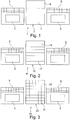
- FIGS. 1-4 show different embodiments of anti-climbing devices according to the invention.
- Figure 1 shows a climbing protection device 1 with a protective shield element 2, which is arranged between two railway buffers 3, 4 and their respective climbing protection elements 5, 6.
- the protective shield element 2 comprises a shield 7 and a cranked section 8.
- the shield 7 is on the impact side (in Fig. 1 against the plane of the drawing, with the upper edge inclined towards the viewer), but the cranked section 8 is even more inclined.
- Shield 7 and cranked section 8, that is to say the entire protective shield element 2 are designed as a continuous surface.
- Figure 2 shows a similar arrangement with a climbing protection device 11, in which the protective shield element 12 is also arranged between the buffers 3, 4 and the climbing protection elements 5, 6. Furthermore, the protective shield element 12 likewise comprises a shield 17 and a cranked section 18, the cranked section 18 and the shield 17 not being designed as a continuous surface, but instead consisting of horizontally extending rods.
- the anti-climbing device 21 comprises a protective shield element 22 with a shield 27 and a cranked section 28, likewise as shown in FIGS Figures 1 and 2 is shown, but shield 27 and cranked section 28 are formed as a lattice structure.
- FIG. 4 A special embodiment is in Figure 4 shown, in which the anti-climbing device 31 has a protective shield element 32, which is also located between the railway buffers 3, 4 and the anti-climbing elements 5, 6.
- the shield 37 is arranged completely between the anti-climbing elements 5, 6.
- the cranked section 38 also additionally projects in a horizontal direction beyond the anti-climbing elements 5, 6, so that a supporting structure can be covered over the entire width by the anti-climbing device 31 and, for example, shields the tank of a tank car.
- Figure 5 is shown schematically in side view how the individual sections of a climbing protection device 1 are inclined on the butt side, while the cranked section 8 is inclined even more on the butt side.
- a claw 9 which is equipped with horizontally running groove structures.
- a rail vehicle 40 is shown that has a support structure 41, on which two buffers 43, 44 are arranged in the lateral area, the Bern area in turn is limited by the geometric specification of how far the plungers 45, 46 of the buffers 43, 44 are pressed can be. In addition, a certain distance from the support structure 41 must be specified. The height of the Bern area is usually assumed to be approx. 2 m. Berner Room B is thus shown in broken lines in a top view and consists of two sub-rooms to the right and left of coupling 47, in which a person can be present when coupling.
- a protective shield element is arranged between the two anti-climbing elements and covers at least part of the area between the anti-climbing elements on the transverse direction of travel.
Abstract
Aufkletterschutzvorrichtung (1, 11, 21 ,31) zum Verhindern des Aufkletterns bei einem Zusammenstoß für bewegliche oder feste Tragstrukturen (41) von Schienenfahrzeugen (40), insbesondere für Güterwagen und/oder Kesselwagen und/oder Container-Tragwagen, welche im seitlichen Bereich wenigstens zwei Eisenbahnpuffer (3, 4, 43, 44) zur Aufnahme von Kräften beim Zusammenstoß mit einem Schienenfahrzeug aufweisen, wobei wenigstens zwei Aufkletterschutzelemente (5, 6) vorgesehen sind, die jeweils so im Bereich der Eisenbahnpuffer (3, 4, 43, 44) anbringbar sind, dass sie den jeweiligen Eisenbahnpuffer in und/oder entgegen der Fahrtrichtung im Bereich oberhalb der Eisenbahnpuffer wenigstens teilweise überragen, dadurch gekennzeichnet, dass zwischen den beiden Aufkletterschutzelementen (5, 6) ein Schutzschildelement (2, 12, 22, 32) angeordnet ist, das wenigstens einen Teil der Fläche, insbesondere vollständig die Fläche zwischen den Aufkletterschutzelementen (5, 6) quer zur Fahrtrichtung abdeckt.Climbing protection device (1, 11, 21, 31) for preventing climbing in the event of a collision for movable or fixed support structures (41) of rail vehicles (40), in particular for freight wagons and / or tank wagons and / or container wagons, which at least in the lateral area Have two railway buffers (3, 4, 43, 44) for absorbing forces when colliding with a rail vehicle, at least two anti-climbing elements (5, 6) being provided, each in the area of the railway buffers (3, 4, 43, 44) can be attached in such a way that they protrude at least partially from the respective railway buffer in and / or against the direction of travel in the area above the railway buffer, characterized in that a protective shield element (2, 12, 22, 32) is arranged between the two anti-climbing elements (5, 6) , the at least part of the area, in particular completely the area between the anti-climbing elements (5, 6) transverse to the direction of travel covers.
Description
Die Erfindung betrifft eine Aufkletterschutzvorrichtung zum Verhindern des Aufkletterns beim Zusammenstoß für bewegliche oder feste Tragstrukturen von Schienenfahrzeugen nach dem Oberbegriff des Anspruchs 1 sowie ein Schienenfahrzeug nach dem Oberbegriff des Anspruchs 7.The invention relates to a climbing protection device for preventing climbing on collision for movable or fixed support structures of rail vehicles according to the preamble of
Aus dem Stand der Technik sind Aufkletterschutzvorrichtungen an Eisenbahnpuffern bekannt, die zum Beispiel eine horizontal verlaufende Rillen- bzw. Riffelstruktur im seitlichen Bereich von Schienenfahrzeugen aufweisen, sodass diese sich beim Zusammenstoß zweier Schienenfahrzeuge miteinander verkrallen und ein Schienenfahrzeug sich nicht über das andere schieben (aufklettern) kann. Verschiedene Kesselwagen bieten für den Fall des Aufkletterns bei einer Kollision eine Verstärkung der Tankwand oder sind mit zusätzlichen Barrieren vor dem Tank ausgerüstet.Climbing protection devices on railroad buffers are known from the prior art which, for example, have a horizontally running groove or corrugation structure in the lateral region of rail vehicles, so that when two rail vehicles collide, they clamp together and one rail vehicle does not slide over the other (climb on). can. Different tank wagons offer a reinforcement of the tank wall in case of climbing in the event of a collision or are equipped with additional barriers in front of the tank.
Aufgabe der Erfindung ist es, für bewegliche oder feste Tragstrukturen von Schienenfahrzeugen, insbesondere für Güter- bzw. Kesselwagen und/oder Container-Tragwagen, einen besonders wirksamen Aufkletterschutz zur Verfügung stellen zu können.The object of the invention is to be able to provide a particularly effective climbing protection for movable or fixed support structures of rail vehicles, in particular for freight or tank wagons and / or container wagons.
Die Erfindung wird, ausgehend von Aufkletterschutzvorrichtungen der eingangs genannten Art, durch die kennzeichnenden Merkmale des Anspruchs 1 bzw. durch die kennzeichnenden Merkmale des Anspruchs 7 gelöst.Starting from anti-climbing devices of the type mentioned at the outset, the invention is achieved by the characterizing features of
Durch die in den abhängigen Ansprüchen genannten Maßnahmen sind vorteilhafte Ausführungen und Weiterbildungen der Erfindung möglich.Advantageous designs and developments of the invention are possible through the measures mentioned in the dependent claims.
Die erfindungsgemäße Aufkletterschutzvorrichtung zum Verhindern des Aufkletterns bei einem Zusammenstoß ist für bewegliche und feste Tragstrukturen von Schienenfahrzeugen gedacht, also grundsätzlich für Lokomotiven bzw. Triebwagen, für Güterwagen, vor allem jedoch für Kesselwagen und/oder Container-Tragwagen, die mit einem Tank ausgestattet sind und bei denen grundsätzlich ein hohes Gefahrenpotential bei Unfällen besteht, da beispielsweise Tankladungen, insbesondere Flüssigkeiten, im Falle einer Kollision, bei der ein Schienenfahrzeug auf ein anderes aufklettert, auslaufen können. Das gleiche Gefahrenpotential besteht freilich bei sog. Druckgaswagen, mit denen Gase unter Druck bzw. Ladungsgemische aus Gas und Flüssiggas in einem Tank transportiert werden. Denn es besteht das Risiko, dass die Tankwand infolge der unmittelbaren Kollision mit dem aufkletternden Fahrzeug reißt.The anti-climbing device according to the invention for preventing climbing in the event of a collision is intended for movable and fixed support structures for rail vehicles, that is to say basically for locomotives or railcars, for freight wagons, but especially for tank wagons and / or container wagons which are equipped with a tank and in which there is basically a high risk of accidents, since tank loads, in particular liquids, can leak in the event of a collision in which one rail vehicle climbs onto another. The same hazard potential exists, of course, in so-called compressed gas wagons, with which gases under pressure or mixed mixtures of gas and liquid gas are transported in a tank. Because there is a risk that the tank wall tears as a result of the direct collision with the climbing vehicle.
Grundsätzlich ist es auch denkbar, die erfindungsgemäße Aufkletterschutzvorrichtung an festen Strukturen wie Prellböcken einzusetzen. Diese Tragstrukturen besitzen in der Regel im seitlichen Bereich, also in dem Bereich, in welchem die Tragstrukturen bei der Fahrt eines Wagens über die Schiene auch miteinander in Verbindung kommen können, wenigstens zwei Eisenbahnpuffer zur Aufnahme von Kräften beim Zusammenstoß mit einem Schienenfahrzeug. Werden zum Beispiel zwei Schienenfahrzeuge miteinander gekoppelt, so stoßen die Fahrzeuge in der Regel mit den Puffern gegeneinander. Beim kontrollierten Aneinanderkoppeln sind die Stöße jedoch vergleichsweise schwach, und die Puffer sind für diesen Betriebsfall dazu ausgebildet, die Stöße abzufedern, ohne dass der Puffer und insbesondere die Schienenfahrzeuge Schaden nehmen. Bei ungewollten Kollisionen im Fahrbetrieb, bei denen die Fahrzeuge weitaus höhere Geschwindigkeiten besitzen und bei einer Kollision wesentlich höhere Energien verzehrt werden müssen, sollen derartige Eisenbahnpuffer ebenfalls in der Lage sein, zumindest einen Teil dieser Energie beim Stoß zu verzehren. Die Eisenbahnpuffer können somit dafür sorgen, dass der Stoß gemildert wird und die Schäden bei den Schienenfahrzeugen und gegebenenfalls den Personen geringer ausfallen, auch wenn oftmals bei schweren Kollisionen und heftigen Stößen nicht die gesamte Energie aus dem Stoß durch die Eisenbahnpuffer aufgebraucht werden kann. Bei derart starken Kollisionen ist aber gewollt, dass zunächst der Eisenbahnpuffer Schaden nimmt, bevor weitere Schäden am Fahrzeug eintreten.In principle, it is also conceivable to use the anti-climbing device according to the invention on solid structures such as buffers. These support structures generally have at least two railroad buffers in the lateral area, that is to say in the area in which the support structures can also come into contact with one another when a car is traveling over the rail, for absorbing forces when they collide with a rail vehicle. If, for example, two rail vehicles are coupled together, the vehicles usually collide with the buffers. With the controlled Coupling the bumps to one another is comparatively weak, however, and the buffers are designed to cushion the bumps in this operating case without the buffers and in particular the rail vehicles being damaged. In the event of undesired collisions during driving, in which the vehicles have much higher speeds and in the event of a collision, significantly higher energies have to be consumed, such railway buffers should also be able to consume at least part of this energy during impact. The railroad buffers can thus ensure that the impact is mitigated and the damage to the rail vehicles and, if necessary, to the people is less, even if the entire energy from the impact cannot be used up by the railroad buffers in the event of severe collisions and violent impacts. With such strong collisions, however, the intention is that the railway buffer is damaged before further damage to the vehicle occurs.
Vielmehr kann es bei heftigen Zusammenstößen sogar dazu kommen, dass die Energie beim Stoß so groß ist, dass sich ein Schienenfahrzeug über das andere schiebt, was generell ein besonderes Problem darstellt, da das aufkletternde Schienenfahrzeug bei einem Personenwagen somit in den Bereich gelangt, in dem sich die Insassen befinden bzw. bei einem Kesselwagen in den Bereich des Tanks, sodass die Gefahr besteht, dass aus dem Tank etwa eine Flüssigkeit ausläuft.Rather, in the event of violent collisions, the energy during the impact can be so great that one rail vehicle pushes over the other, which is generally a particular problem, since the climbing rail vehicle in a passenger car thus reaches the area in which the occupants are in the area of the tank or in the case of a tank wagon, so there is a risk that a liquid might leak out of the tank.
Aus diesem Grund sind erfindungsgemäß zunächst wenigstens zwei Aufkletterschutzelemente vorgesehen, die jeweils so im Bereich der Eisenbahnpuffer anbringbar sind, dass sie den jeweiligen Eisenbahnpuffer in bzw. entgegen der Fahrtrichtung wenigstens teilweise im Bereich oberhalb der Eisenbahnpuffer überragen.For this reason, according to the invention, at least two anti-climbing elements are initially provided, each of which can be attached in the area of the railway buffers in such a way that they protrude at least partially in the area above the railway buffers in or against the direction of travel.
Seitliche Aufkletterschutzmodule bieten i.d.R. den eigentlichen Schutz gegen Aufklettern. Dazu überragen sie den Puffer über seinen Einfederungsweg hinaus. Sonst wird bei einer Kollision gar keine ausreichende Überlappung der beiden Unfallgegner in Fahrzeuglängsrichtung erreicht, die aber erforderlich ist, damit in der Vertikalrichtung die gewünschte Blockadefunktion zwischen Aufkletterschutzmodul und gegnerischem Fahrzeug/Eisenbahnpuffer eintritt. Nun ist es aber andererseits erforderlich, dass im Alltagsbetrieb kein Verhaken stattfinden darf und deshalb das Aufkletterschutzmodul den regulären Einfederungsweg unter keinen Umständen blockieren darf. Daraus folgt, dass ein seitliches Aufkletterschutzmodul insbesondere dann seine beabsichtigte Funktion entwickeln kann, wenn es entweder nur einmal pro Fahrzeugende installiert wird oder in Fahrzeugquerrichtung asymmetrisch zu beiden Seiten rechts und links in Fahrtrichtung ausgeführt wird und stets gegen ein entsprechendes Aufkletterschutzmodul gekuppelt und damit konjugiert gepaart wird, oder aber wenn es den Eisenbahnpuffer weniger weit überragt als es das Ende des regulären Einfederungswegs darstellt und der Eisenbahnpuffer als sog. Crashpuffer ausgeführt ist, der bei stärkeren Kollisionen einen zusätzlichen Einfederungsweg in Form seiner Crashdeformationsfähigkeit besitzt und damit die erforderliche Annäherung zwischen den Kollisionsgegnern erlaubt.Side climbing protection modules usually offer the actual protection against climbing. To do this, they protrude the buffer beyond its deflection path. Otherwise, in the event of a collision, the two opponents of the accident do not sufficiently overlap in the longitudinal direction of the vehicle, but this is necessary so that the desired blocking function between the anti-climbing module and the opposing vehicle / railway buffer occurs in the vertical direction. Now, on the other hand, it is necessary that no snagging may occur in everyday operation and therefore the climbing protection module must not block the regular deflection path under any circumstances. It follows that a lateral anti-climbing module can develop its intended function in particular if it is either installed only once per vehicle end or is designed asymmetrically on both sides to the right and left in the direction of travel in the transverse direction of the vehicle and is always coupled to a corresponding anti-climbing module and thus conjugated , or if it protrudes less than the railway buffer than it represents the end of the regular deflection and the railway buffer is designed as a so-called crash buffer, which has an additional deflection in the form of its crash deformability in the event of stronger collisions and thus allows the required approach between the opponents of the collision.
Um die Wirksamkeit des Aufkletterschutzes noch steigern zu können, ist zwischen den beiden Aufkletterschutzelementen ein Schutzschildelement angeordnet, dass wenigstens einen Teil der Fläche, insbesondere vollständig die Fläche zwischen den Aufkletterschutzelementen quer zur Fahrtrichtung abdeckt. Diese Vorrichtung ist zunächst mit einem vergleichbar geringen baulichen Aufwand verbunden, da entweder eine einfache Befestigung im seitlichen Bereich der Tragstruktur ausreicht, gegebenenfalls sogar eine Befestigung an der Aufkletterschutzvorrichtung selbst denkbar ist.In order to be able to increase the effectiveness of the anti-climbing protection, a protective shield element is arranged between the two anti-climbing elements that covers at least part of the area, in particular completely, the area between the anti-climbing elements transverse to the direction of travel. This device is initially of a comparably small size structural effort, since either a simple attachment in the lateral area of the support structure is sufficient, possibly even an attachment to the anti-climbing device itself is conceivable.
Die Aufkletterschutzelemente dienen zunächst dazu, das Aufklettern zu verhindern, indem diese z.B. Rillen- bzw. Riffelstrukturen aufweisen, welche im Wesentlichen in horizontaler Richtung verlaufen. Insbesondere dann, wenn zwei Tragstrukturen gleicher Bauart miteinander kollidieren, können die Aufkletterschutzvorrichtungen miteinander verhaken, die an den jeweiligen Tragstrukturen angebracht sind. Damit sodann dennoch kein Aufklettern stattfinden kann, müssten die gegeneinander gedrückten Riffelstrukturen aneinander vorbei gleiten, was zumindest nicht ohne Weiteres möglich ist bzw. sehr viel Energie erfordert. Dennoch sind die Aufkletterschutzelemente nach dem Stand der Technik herkömmlicherweise vergleichsweise klein.The climbing protection elements serve first of all to prevent climbing by e.g. Have groove or corrugated structures which run essentially in the horizontal direction. In particular, when two support structures of the same type collide with one another, the anti-climbing devices that are attached to the respective support structures can get caught. So that climbing cannot take place, the corrugated structures that are pressed against each other would have to slide past one another, which is at least not easily possible or requires a great deal of energy. Nevertheless, the anti-climbing elements according to the prior art are conventionally comparatively small.
Grundsätzlich gibt es die seitlichen Aufkletterschutzmodule in verschiedenen Ansätzen: Allen gemein ist, dass sie den Puffer nach oben (optional oder/und unten) zumindest teilweise überragen. Dabei müssen sie aber nicht unbedingt eine horizontale Riffelstruktur aufweisen, damit sie sich verhaken. Mitunter handelt es sich nur um eine Ausführung mit nur einer horizontalen Ebene, da man hier davon ausgeht, dass gegenüberliegende Aufkletterschutzmodule damit ein minimales Risiko haben, sich in Fahrzeuglängsrichtung im Weg zu stehen. Es reicht ein minimaler vertikaler Höhenversatz, dass diese aneinander vorbeigleiten können. Der "Verhakungseffekt" tritt dann durch räumliche Überlappung in Fahrzeuglängsrichtung und gegenständliche Überdeckung und damit Blockade in vertikaler Richtung nach möglichst geringer Vertikaler Bewegung statt. Derlei ausgeführte Aufkletterschutzmodule weisen dann auch in Längsrichtung keine kontrollierte Nachgiebigkeit auf, sondern sind vielmehr überaus steif und penetrieren damit ggf. den Kollisionsgegner.Basically, there are different approaches to the side climbing protection modules: What they all have in common is that they at least partially protrude above the buffer (optional or / and below). However, they do not necessarily have to have a horizontal corrugated structure for them to get caught. Sometimes it is only a version with only one horizontal level, since it is assumed here that opposite climbing protection modules have a minimal risk of standing in the way of the vehicle in the longitudinal direction. A minimal vertical height offset is enough for them to slide past each other. The "hooking effect" then occurs due to spatial overlap in the longitudinal direction of the vehicle and physical coverage and thus blockage in the vertical Direction after as little vertical movement as possible. Climbing protection modules of this type then do not have any controlled flexibility in the longitudinal direction, but rather are extremely stiff and thus penetrate the collision opponent, if necessary.
Zudem ist die Wirksamkeit der Aufkletterschutzelemente nicht immer präzise vorhersagbar, insbesondere dann, wenn zwei Tragstrukturen unterschiedlicher Bauart kollidieren, die unterschiedliche Aufkletternschutzelemente aufweisen oder von denen eine Tragstruktur zum Beispiel nicht mit Aufkletterschutzelementen ausgestattet ist.In addition, the effectiveness of the anti-climber elements is not always precisely predictable, in particular when two supporting structures of different designs collide, which have different anti-climbing elements or of which one supporting structure is not equipped with anti-climbing elements, for example.
Gerade im Fall von Kesselwagen werden daher oft auf dem Schienenfahrzeug unmittelbar vor dem Tank zusätzliche Barrieren errichtet oder es wird die Tankwand selbst noch einmal verstärkt.Especially in the case of tank wagons, additional barriers are often built on the rail vehicle directly in front of the tank or the tank wall itself is reinforced again.
Erfindungsgemäß wird durch das zusätzliche Schutzschildelement zwischen den beiden Aufkletterschutzelementen ermöglicht, dass das kollidierende Schienenfahrzeug bzw. dessen Tragstruktur vorzeitig abgefangen werden kann, bevor das eigentliche Aufklettern erfolgt. Das erfindungsgemäße Schutzschildelement bildet eine zusätzliche Barriere, da das Schienenfahrzeug im seitlichen Bereich voran mit der Tragstruktur dieses Schutzschildelement durchbrechen bzw. überwinden müsste. Es bietet daher grundsätzlich bereits einen Vorteil gegenüber einer Tankwandverstärkung bzw. gegenüber einer auf dem Schienenfahrzeug angebrachten Barriere, da diese erst ihre Wirksamkeit entfalten kann, wenn das Schienenfahrzeug bereits zumindest teilweise aufgeklettert ist.According to the invention, the additional protective shield element between the two anti-climbing elements makes it possible for the colliding rail vehicle or its support structure to be intercepted prematurely before the actual climbing takes place. The protective shield element according to the invention forms an additional barrier, since the rail vehicle would have to break through or overcome this protective shield element in the lateral area with the supporting structure. In principle, therefore, it already offers an advantage over a tank wall reinforcement or over a barrier attached to the rail vehicle, since this can only be effective when the rail vehicle has already climbed at least partially.
Darüber hinaus bietet sie gegenüber Tankwandverstärkungen und insbesondere gegenüber zusätzlichen Barrieren auf dem Schienenfahrzeug einen entscheidenden Platzvorteil, da dieser Bereich in der Regel dazu genutzt werden kann oder soll, dass Personen bei der Arbeit mit dem Schienenfahrzeug diesen Bereich betreten können oder müssen.In addition, it offers a decisive space advantage compared to tank wall reinforcements and, in particular, additional barriers on the rail vehicle, since this area can or should generally be used to enable people to or have to enter this area when working with the rail vehicle.
Zudem kann mit der erfindungsgemäßen Aufkletterschutzvorrichtung das technische Vorurteil überwunden werden, dass im seitlichen Bereich zwischen den Eisenbahnpuffern per se jeglicher, zur Verfügung stehender Platz freizuhalten ist. Beim nicht vollautomatisierten Kuppeln von Schienenfahrzeugen muss regelmäßig eine Person zwischen den jeweiligen Tragstrukturen der Schienenfahrzeuge stehen, um den Kupplungsvorgang zu überwachen bzw. zu steuern. Zur Verfügung stehen hierzu zwischen den Tragstrukturen im Bereich der sich berührenden Fahrzeug-Enden die beiden Teilräume zwischen dem jeweiligen Eisenbahnpuffer und der Kupplung, die in der Regel in der Mitte der Tragstruktur angebracht ist. Aus Sicherheitsgründen ist dieser Raum (der sog. "Berner Raum") folglich freizuhalten, damit die dort befindliche Person beim Kuppeln der Fahrzeuge nicht eingequetscht wird. In Schienenrichtung beträgt der Abstand zwischen dem Fahrzeug und einem vollständig eingedrückten Puffer (das heißt bis zu dem Punkt eingedrückt, an dem der Puffer den Stoß beim Kuppeln höchstens noch elastisch abfedern kann) etwa 30 cm. Es ist also möglich, in diesem Bereich gegebenenfalls auch über die gesamte Breite der Tragstruktur eine zusätzliche Struktur wie ein Schutzschildelement anzubringen, ohne den Berner Raum damit zu verletzen und die Sicherheit von Personen zu gefährden.In addition, the anti-climbing device according to the invention can be used to overcome the technical prejudice that in the lateral area between the railway buffers, any available space must be kept free. In the case of not fully automated coupling of rail vehicles, a person must regularly stand between the respective supporting structures of the rail vehicles in order to monitor or control the coupling process. For this purpose, the two subspaces between the respective railway buffer and the coupling, which is usually attached in the middle of the supporting structure, are available between the supporting structures in the area of the contacting vehicle ends. For safety reasons, this room (the so-called "Bern room") must therefore be kept clear so that the person there is not squeezed when the vehicles are coupled. In the direction of the rail, the distance between the vehicle and a fully pressed-in buffer (i.e. pressed in to the point at which the buffer can at most elastically cushion the impact when coupling) is approximately 30 cm. It is therefore possible to install an additional structure such as a protective element in this area, if necessary, over the entire width of the supporting structure, without thereby injuring the Bern area and endangering the safety of people.
Wird der Berner Raum beim automatisierten Kuppeln nicht benötigt, können entsprechende Strukturen, wie das erfindungsgemäße Schutzschildelement, ohnehin angebracht werden.If the Bern area is not required for automated coupling, appropriate structures, such as the protective shield element according to the invention, can be attached anyway.
Bei einem Ausführungsbeispiel der Erfindung kann in bevorzugter Weise das Schutzschildelement eine eigene Befestigungsvorrichtung zur Befestigung am Schienenfahrzeug aufweisen. Hierdurch kann eine von der Befestigung des Aufkletterschutzes unabhängige Befestigung erhalten werden, insbesondere, wenn im Falle einer Kollision die Stoßenergie so groß ist, dass der Eisenbahnpuffer und/oder die Tragstruktur beschädigt bzw. zerstört wird/werden. Darüber hinaus kann auch eine verbesserte Abstützung erzielt werden, da zur Befestigung des Schutzschildelementes (je nach Bauart der Tragstruktur) gegebenenfalls die gesamte Breite der Tragstruktur oder zumindest ein großer Teil davon zur Verfügung steht.In one embodiment of the invention, the protective shield element can preferably have its own fastening device for fastening to the rail vehicle. In this way, a fastening which is independent of the fastening of the climbing protection can be obtained, in particular if, in the event of a collision, the impact energy is so great that the railway buffer and / or the supporting structure is / are damaged or destroyed. In addition, an improved support can also be achieved, since the entire width of the support structure or at least a large part thereof may be available for fastening the protective shield element (depending on the type of support structure).
Es kann auch für wenigstens zwei oder alle drei Bauteile, nämlich erstens den Eisenbahnpuffer, zweitens das Aufkletterschutzelement und drittens das Schutzschildelement jeweils eine gemeinsame Befestigungsvorrichtung zur Befestigung an der Tragstruktur vorgesehen sein, sodass die Aufkletterschutzvorrichtung ein kompaktes Bauteil ausbildet.A common fastening device for fastening to the supporting structure can also be provided for at least two or all three components, namely firstly the railway buffer, secondly the anti-climbing element and thirdly the protective shield element, so that the anti-climbing device forms a compact component.
Grundsätzlich ist es auch denkbar, das Schutzschildelement auf der Oberseite des Schienenfahrzeugs gegebenenfalls zusätzlich abzustützen. Diese Maßnahme kann dann vorgesehen werden, wenn auf dem Schienenfahrzeug ausreichend Platz vorhanden ist, um eine solche Abstützung vorzunehmen. Im Grunde genügt es in vielen Fällen, wenn die Abstützung lediglich im Randbereich des Schienenfahrzeugs auf dessen Oberfläche erfolgt. Da die Kräfte beim Aufklettern zusätzlich eine Komponente in vertikaler Richtung besitzen, kann gegebenenfalls ein Schutzschildelement somit noch besser und wirkungsvoller abgestützt werden.In principle, it is also conceivable to optionally additionally support the protective shield element on the top of the rail vehicle. This measure can be provided if there is sufficient space on the rail vehicle to carry out such a support. Basically, it is sufficient in many cases if the support is carried out only in the edge region of the rail vehicle on its surface. Because the forces when climbing additionally have a component in the vertical direction, a protective shield element can thus be supported even better and more effectively.
Das Schutzschildelement kann je nach Ausführungsform der Erfindung verschieden ausgebildet sein. Grundsätzlich kann es sich um eine geschlossene Wand handeln, die ein hohes Maß an Stabilität besitzen kann und auch ein hohes Maß an Abschirmung, gerade auch gegenüber heraustretenden Einzelteilen bei einer Kollision, bietet. Stattdessen kann grundsätzlich aber auch ein Gitter oder sogar ein Netz verwendet werden, welches je nach Stärke der Gitterstäbe einen Gewichtsvorteil mit sich bringen kann. Statt einem Gitter können grundsätzlich auch Stangen vorgesehen sein. Sind die Gitterstäbe oder die Stangen zu dünn gewählt, kann sich dies grundsätzlich nicht nur negativ auf die Stabilität auswirken, sondern es kann auch schwierig sein, eine solche Struktur stabil zu befestigen. Gleiche Befestigungsschwierigkeiten können bei einem Netz auftreten, das dafür allerdings auch in der Regel sehr leicht ist. Sind die Stangen bzw. Stäbe jedoch vergleichsweise dick bzw. sogar noch massiv ausgebildet, können diese hohe Biegemomente aufweisen und auch somit einen hervorragenden Schutz gegen das Aufklettern bieten.The protective shield element can be designed differently depending on the embodiment of the invention. Basically, it can be a closed wall, which can have a high degree of stability and also offers a high degree of shielding, especially against individual parts emerging in the event of a collision. Instead, however, a grid or even a net can in principle be used which, depending on the strength of the grid bars, can bring about a weight advantage. In principle, rods can also be provided instead of a grid. If the bars or bars are too thin, this can not only have a negative effect on the stability, but it can also be difficult to attach such a structure stably. The same fastening problems can occur with a network, which, however, is usually very easy. However, if the bars or rods are comparatively thick or even solid, they can have high bending moments and thus also offer excellent protection against climbing.
Um die Wirksamkeit, Stabilität und Widerstandsfähigkeit noch einmal erhöhen zu können, kann das Schutzschildelement einen gekröpften Abschnitt aufweisen, der insbesondere vom Schienenfahrzeug und/oder der Tragstruktur, an welcher die Aufkletterschutzvorrichtung befestigbar ist, weg geneigt ist bzw. stoßseitig geneigt ist. Da ein solcher gekröpfter Abschnitt noch einmal zur Stoßseite hin geneigt ist, ist es bei einem aufkletternden Fahrzeug noch einmal schwieriger, dieses Hindernis entsprechend zu überwinden. Das aufkletternde Fahrzeug kann somit vorzeitig und wirksam abgefangen werden.In order to be able to increase the effectiveness, stability and resilience once again, the protective shield element can have a cranked section which is inclined away from the rail vehicle and / or the supporting structure, to which the anti-climbing device can be fastened, or is inclined on the impact side. Since such a cranked section is again inclined towards the impact side, it is even more difficult for a climbing vehicle To overcome the obstacle accordingly. The climbing vehicle can thus be intercepted early and effectively.
Im Übrigen kann bei einer bevorzugten Weiterbildung der Erfindung auch das Schutzschildelement eine Kralle aufweisen, die insbesondere am gekürzten Abschnitt angebracht sein kann, und welche vorzugsweise mit einer Riffelstruktur ausgestattet ist. Durch die Riffelstruktur wird noch einmal zusätzlich der Vorteil geboten, dass diese in der Regel horizontale Struktur überwunden werden muss. Zudem ist regelmäßig die entsprechende Kralle noch einmal mehr stoßseitig geneigt, sodass ein noch stärkeres mechanisches Hindernis zur Verfügung gestellt wird. Die Wirksamkeit und Sicherheit können somit verbessert werden.In addition, in a preferred development of the invention, the protective shield element can also have a claw, which can be attached in particular to the shortened section and which is preferably equipped with a corrugated structure. The corrugated structure offers the additional advantage that this usually horizontal structure has to be overcome. In addition, the corresponding claw is regularly inclined once more on the thrust side, so that an even stronger mechanical obstacle is made available. The effectiveness and safety can thus be improved.
Die Kralle kann zum Beispiel durch Umbiegen, Umbördeln oder Abkanten des entsprechenden Bereichs des Schutzschildelements gefertigt werden, vorteilhafterweise also durch kostengünstige Standardverfahren der Metallbearbeitung.The claw can be produced, for example, by bending, flanging or folding the corresponding area of the protective shield element, that is to say advantageously by means of inexpensive standard methods of metalworking.
Wie bereits dargestellt, kann das Schutzschildelement grundsätzlich auch an wenigstens einem der Aufkletterschutzelemente befestigt sein. Hierdurch kann eine zusätzliche Flexibilität beim Befestigen am Fahrzeug erreicht werden, da keine zusätzlichen Befestigungsstrukturen für das Schutzschildelement notwendig sind. Es ist aber auch denkbar, dass das Schutzschildelement zusätzlich oder ausschließlich daran befestigt ist.As already shown, the protective shield element can in principle also be attached to at least one of the anti-climbing elements. As a result, additional flexibility can be achieved when fastening to the vehicle, since no additional fastening structures are required for the protective shield element. However, it is also conceivable that the protective shield element is additionally or exclusively attached to it.
Dementsprechend zeichnet sich ein erfindungsgemäßes Schienenfahrzeug, insbesondere ein Güterwagen beziehungsweise Kesselwagen dadurch aus, dass eine Aufkletterschutzvorrichtung gemäß der Erfindung bzw. gemäß einem Ausführungsbeispiel der Erfindung vorgesehen ist, welche am Kopfstück des Schienenfahrzeug angebracht ist, wobei im seitlichen Bereich wenigstens zwei Eisenbahnpuffer zur Aufnahme von Kräften bei einem Zusammenstoß vorhanden sind und wenigstens zwei Aufkletterschutzelemente jeweils so im Bereich der Eisenbahnpuffer angebracht sind, dass sie den jeweiligen Eisenbahnpuffer in bzw. entgegen der Fahrtrichtung wenigstens teilweise überragen. Mit einem derartigen Schienenfahrzeug können die zuvor genannten Vorteile erreicht werden.Accordingly, a rail vehicle according to the invention, in particular a freight wagon, respectively Tank car characterized in that a climbing protection device according to the invention or according to an embodiment of the invention is provided, which is attached to the head piece of the rail vehicle, with at least two railroad buffers for absorbing forces in the event of a collision being present in the lateral area and at least two climbing protection elements in each case are attached in the area of the railway buffers so that they protrude at least partially from the respective railway buffer in or against the direction of travel. The advantages mentioned above can be achieved with such a rail vehicle.
Eine besondere Verwendung kommt gerade im Zusammenhang mit einem Kesselwagen in Betracht. Sollte der Inhalt des Tanks des Kesselwagens ein besonderes Gefahrenpotential bieten, so können gegebenenfalls auch herkömmliche Sicherheitsmaßnahmen wie eine Verstärkung der Tankwand oder eine zusätzliche Barriere noch hinzugefügt werden. Die erfindungsgemäße Aufkletterschutzvorrichtung benötigt nämlich grundsätzlich vorteilhafterweise nicht den für diese Zwecke erforderlichen Raum. In gleicher Weise ist ein Einsatz bei Container-Tragwagen möglich.A particular use comes into consideration in connection with a tank car. If the content of the tank car tank poses a special hazard potential, conventional safety measures such as reinforcing the tank wall or an additional barrier can also be added if necessary. In principle, the anti-climbing device according to the invention advantageously does not require the space required for these purposes. In the same way, use with container wagons is possible.
Darüber hinaus bzw. zusätzlich kann das Schutzschildelement an der Kopfseite des Schienenfahrzeugs grundsätzlich auch auf dem Schienenfahrzeug abgestützt sein, um im Kollisionsfall eine verbesserte mechanische Stabilität zu erhalten.In addition or in addition, the protective shield element on the head side of the rail vehicle can in principle also be supported on the rail vehicle in order to obtain improved mechanical stability in the event of a collision.
Ausführungsbeispiele der Erfindung sind in den Zeichnungen dargestellt und werden nachstehend unter Angabe weiterer Einzelheiten und Vorteile näher erläutert. Im Einzelnen zeigen:
- Fig. 1-4:
- verschiedene Aufkletterschutzvorrichtungen gemäß der Erfindung (gesehen in Fahrtrichtung),
- Fig. 5
- eine Seitenansicht eine Aufkletterschutzvorrichtung gemäß der Erfindung mit gekröpftem Abschnitt und Kralle, sowie
- Fig. 6:
- eine Darstellung des Berner Raumes bei einem Schienenfahrzeug.
- Fig. 1-4:
- various anti-climbing devices according to the invention (viewed in the direction of travel),
- Fig. 5
- a side view of a climbing protection device according to the invention with a cranked portion and claw, and
- Fig. 6:
- a representation of the Bern area in a rail vehicle.
Die
Die Aufkletterschutzvorrichtung 21 umfasst ein Schutzschildelement 22 mit einem Schild 27 und einen gekröpften Abschnitt 28, ebenfalls wie es in den
Eine besondere Ausführungsform ist in
In
In
Allen Ausführungsbeispielen und Weiterbildungen der Erfindung ist gemeinsam, dass zwischen den beiden Aufkletterschutzelementen ein Schutzschildelement angeordnet ist das wenigstens einen Teil der Fläche zwischen den auf Kletterschutzelementen quer zur Fahrtrichtung abdeckt.All of the exemplary embodiments and developments of the invention have in common that a protective shield element is arranged between the two anti-climbing elements and covers at least part of the area between the anti-climbing elements on the transverse direction of travel.
- 11
- AufkletterschutzvorrichtungAufkletterschutzvorrichtung
- 22
- SchutzschildelementShield element
- 3, 43, 4
- EisenbahnpufferRailway buffer
- 5, 65, 6
- AufkletterschutzelementeAufkletterschutzelemente
- 77
- Schildsign
- 88th
- gekröpfter Abschnittcranked section
- 99
- Kralleclaw
- 1111
- AufkletterschutzvorrichtungAufkletterschutzvorrichtung
- 1212
- SchutzschildelementShield element
- 1717
- Schildsign
- 1818
- gekröpfter Abschnittcranked section
- 2121
- AufkletterschutzvorrichtungAufkletterschutzvorrichtung
- 2222
- SchutzschildelementShield element
- 2727
- Schildsign
- 2828
- gekröpfter Abschnittcranked section
- 3131
- AufkletterschutzvorrichtungAufkletterschutzvorrichtung
- 3232
- SchutzschildelementShield element
- 3737
- Schildsign
- 3838
- gekröpfter Abschnittcranked section
- 4040
- Schienenfahrzeugtrack vehicle
- 4141
- Tragstruktursupporting structure
- 43, 4443, 44
- Pufferbuffer
- 45, 4645, 46
- Stößeltappet
- 4747
- Kupplungclutch
- BB
- Berner RaumBern area
Claims (9)
Priority Applications (1)
| Application Number | Priority Date | Filing Date | Title |
|---|---|---|---|
| PL19187061T PL3608197T3 (en) | 2018-08-07 | 2019-07-18 | Climbing safety device with protective shield element |
Applications Claiming Priority (1)
| Application Number | Priority Date | Filing Date | Title |
|---|---|---|---|
| EP18187772 | 2018-08-07 |
Publications (2)
| Publication Number | Publication Date |
|---|---|
| EP3608197A1 true EP3608197A1 (en) | 2020-02-12 |
| EP3608197B1 EP3608197B1 (en) | 2022-03-02 |
Family
ID=63173974
Family Applications (1)
| Application Number | Title | Priority Date | Filing Date |
|---|---|---|---|
| EP19187061.7A Active EP3608197B1 (en) | 2018-08-07 | 2019-07-18 | Climbing safety device with protective shield element |
Country Status (3)
| Country | Link |
|---|---|
| EP (1) | EP3608197B1 (en) |
| HU (1) | HUE058948T2 (en) |
| PL (1) | PL3608197T3 (en) |
Citations (6)
| Publication number | Priority date | Publication date | Assignee | Title |
|---|---|---|---|---|
| DE19833935A1 (en) * | 1997-07-28 | 1999-02-04 | Hutchinson | Protective device for container or tank on railway wagon |
| DE102006050028A1 (en) * | 2006-10-24 | 2008-04-30 | Sieghard Schneider | Anti-climbing protective device for rail vehicles, has molded parts, which projects out of vehicle front, and has catch made of cells that are formed by level rods in direction of travel |
| EP2163454A1 (en) * | 2008-09-16 | 2010-03-17 | Vossloh Locomotives GmbH | Anti-climb device for locomotive bumpers |
| DE102013009121B3 (en) * | 2013-05-29 | 2014-07-31 | Waggonbau Graaff Gmbh | Overfill protection for rail vehicles |
| WO2015120882A1 (en) * | 2014-02-11 | 2015-08-20 | Siemens Aktiengesellschaft | Override protection device for a rail vehicle |
| RU177726U1 (en) * | 2016-12-27 | 2018-03-06 | РЕЙЛ 1520 АйПи ЛТД | WAGON TANK |
-
2019
- 2019-07-18 PL PL19187061T patent/PL3608197T3/en unknown
- 2019-07-18 HU HUE19187061A patent/HUE058948T2/en unknown
- 2019-07-18 EP EP19187061.7A patent/EP3608197B1/en active Active
Patent Citations (6)
| Publication number | Priority date | Publication date | Assignee | Title |
|---|---|---|---|---|
| DE19833935A1 (en) * | 1997-07-28 | 1999-02-04 | Hutchinson | Protective device for container or tank on railway wagon |
| DE102006050028A1 (en) * | 2006-10-24 | 2008-04-30 | Sieghard Schneider | Anti-climbing protective device for rail vehicles, has molded parts, which projects out of vehicle front, and has catch made of cells that are formed by level rods in direction of travel |
| EP2163454A1 (en) * | 2008-09-16 | 2010-03-17 | Vossloh Locomotives GmbH | Anti-climb device for locomotive bumpers |
| DE102013009121B3 (en) * | 2013-05-29 | 2014-07-31 | Waggonbau Graaff Gmbh | Overfill protection for rail vehicles |
| WO2015120882A1 (en) * | 2014-02-11 | 2015-08-20 | Siemens Aktiengesellschaft | Override protection device for a rail vehicle |
| RU177726U1 (en) * | 2016-12-27 | 2018-03-06 | РЕЙЛ 1520 АйПи ЛТД | WAGON TANK |
Also Published As
| Publication number | Publication date |
|---|---|
| HUE058948T2 (en) | 2022-09-28 |
| PL3608197T3 (en) | 2022-07-11 |
| EP3608197B1 (en) | 2022-03-02 |
Similar Documents
| Publication | Publication Date | Title |
|---|---|---|
| WO2008034745A1 (en) | Head module for a rail vehicle | |
| DE102018133181B3 (en) | Personal protection device for fastening to the underside of a rail vehicle | |
| EP2277762B1 (en) | Railway vehicle with crash absorber, in particular tramway | |
| DE4224998C1 (en) | Protective crash barrier for highways - comprises posts anchored in ground, deformation profile on road side, upper and lower longitudinal rails | |
| CH658631A5 (en) | RAIL VEHICLE WITH CENTER BUFFER COUPLING. | |
| DE602005004131T2 (en) | DEFORMABLE FRAME FOR A VEHICLE CABIN | |
| DE102006050028B4 (en) | Device on the vehicle front of rail vehicles | |
| DE102015111995B4 (en) | Bumper arrangement with closing plate | |
| EP0612647B1 (en) | Device for protection for passengers from injuries during a collision of railway trains | |
| EP2999609B1 (en) | Rail vehicle with a completely retractable coupling | |
| EP1633615B1 (en) | Anti-climbing device for railway carriages | |
| DE102013009121B3 (en) | Overfill protection for rail vehicles | |
| DE102006056498B4 (en) | Rear underride guard | |
| DE4406129A1 (en) | Vehicle impact damping equipment | |
| DE4332289A1 (en) | Device for preventing rail vehicles from being pushed upwards as a consequence of an impact resulting from an accident | |
| DE102012221313B3 (en) | Over-buffering protection device for crash buffer arranged between lower frame for railway carriage and buffer, has lateral web on both sides of base plate projecting beyond beveled portion of base plate, and ribs above folded base plate | |
| EP3640113A1 (en) | Energy receiving device and rail vehicle | |
| EP3608197B1 (en) | Climbing safety device with protective shield element | |
| EP2808222B1 (en) | Buffer override protection for rail vehicles | |
| EP0370459B1 (en) | Front part of a railway car | |
| EP0816197B1 (en) | Protective gear for vessels of railroad cars, especially for tank cars or closed bulk freight wagons | |
| EP3560787A1 (en) | Rail vehicle | |
| DE202008011203U1 (en) | Vehicle restraint system on traffic routes | |
| DE19855830C1 (en) | Collision absorber for tram has shock absorber and crumple zone in from of chassis to support buffer | |
| EP3071468A1 (en) | Override protection device for a rail vehicle |
Legal Events
| Date | Code | Title | Description |
|---|---|---|---|
| PUAI | Public reference made under article 153(3) epc to a published international application that has entered the european phase |
Free format text: ORIGINAL CODE: 0009012 |
|
| STAA | Information on the status of an ep patent application or granted ep patent |
Free format text: STATUS: THE APPLICATION HAS BEEN PUBLISHED |
|
| AK | Designated contracting states |
Kind code of ref document: A1 Designated state(s): AL AT BE BG CH CY CZ DE DK EE ES FI FR GB GR HR HU IE IS IT LI LT LU LV MC MK MT NL NO PL PT RO RS SE SI SK SM TR |
|
| AX | Request for extension of the european patent |
Extension state: BA ME |
|
| STAA | Information on the status of an ep patent application or granted ep patent |
Free format text: STATUS: REQUEST FOR EXAMINATION WAS MADE |
|
| 17P | Request for examination filed |
Effective date: 20200505 |
|
| RBV | Designated contracting states (corrected) |
Designated state(s): AL AT BE BG CH CY CZ DE DK EE ES FI FR GB GR HR HU IE IS IT LI LT LU LV MC MK MT NL NO PL PT RO RS SE SI SK SM TR |
|
| GRAP | Despatch of communication of intention to grant a patent |
Free format text: ORIGINAL CODE: EPIDOSNIGR1 |
|
| STAA | Information on the status of an ep patent application or granted ep patent |
Free format text: STATUS: GRANT OF PATENT IS INTENDED |
|
| INTG | Intention to grant announced |
Effective date: 20211019 |
|
| GRAS | Grant fee paid |
Free format text: ORIGINAL CODE: EPIDOSNIGR3 |
|
| GRAA | (expected) grant |
Free format text: ORIGINAL CODE: 0009210 |
|
| STAA | Information on the status of an ep patent application or granted ep patent |
Free format text: STATUS: THE PATENT HAS BEEN GRANTED |
|
| AK | Designated contracting states |
Kind code of ref document: B1 Designated state(s): AL AT BE BG CH CY CZ DE DK EE ES FI FR GB GR HR HU IE IS IT LI LT LU LV MC MK MT NL NO PL PT RO RS SE SI SK SM TR |
|
| REG | Reference to a national code |
Ref country code: GB Ref legal event code: FG4D Free format text: NOT ENGLISH |
|
| REG | Reference to a national code |
Ref country code: CH Ref legal event code: EP Ref country code: AT Ref legal event code: REF Ref document number: 1472024 Country of ref document: AT Kind code of ref document: T Effective date: 20220315 |
|
| REG | Reference to a national code |
Ref country code: DE Ref legal event code: R096 Ref document number: 502019003538 Country of ref document: DE |
|
| REG | Reference to a national code |
Ref country code: IE Ref legal event code: FG4D Free format text: LANGUAGE OF EP DOCUMENT: GERMAN |
|
| REG | Reference to a national code |
Ref country code: RO Ref legal event code: EPE |
|
| REG | Reference to a national code |
Ref country code: LT Ref legal event code: MG9D |
|
| REG | Reference to a national code |
Ref country code: SE Ref legal event code: TRGR |
|
| REG | Reference to a national code |
Ref country code: NL Ref legal event code: MP Effective date: 20220302 |
|
| PG25 | Lapsed in a contracting state [announced via postgrant information from national office to epo] |
Ref country code: RS Free format text: LAPSE BECAUSE OF FAILURE TO SUBMIT A TRANSLATION OF THE DESCRIPTION OR TO PAY THE FEE WITHIN THE PRESCRIBED TIME-LIMIT Effective date: 20220302 Ref country code: NO Free format text: LAPSE BECAUSE OF FAILURE TO SUBMIT A TRANSLATION OF THE DESCRIPTION OR TO PAY THE FEE WITHIN THE PRESCRIBED TIME-LIMIT Effective date: 20220602 Ref country code: LT Free format text: LAPSE BECAUSE OF FAILURE TO SUBMIT A TRANSLATION OF THE DESCRIPTION OR TO PAY THE FEE WITHIN THE PRESCRIBED TIME-LIMIT Effective date: 20220302 Ref country code: HR Free format text: LAPSE BECAUSE OF FAILURE TO SUBMIT A TRANSLATION OF THE DESCRIPTION OR TO PAY THE FEE WITHIN THE PRESCRIBED TIME-LIMIT Effective date: 20220302 Ref country code: ES Free format text: LAPSE BECAUSE OF FAILURE TO SUBMIT A TRANSLATION OF THE DESCRIPTION OR TO PAY THE FEE WITHIN THE PRESCRIBED TIME-LIMIT Effective date: 20220302 Ref country code: BG Free format text: LAPSE BECAUSE OF FAILURE TO SUBMIT A TRANSLATION OF THE DESCRIPTION OR TO PAY THE FEE WITHIN THE PRESCRIBED TIME-LIMIT Effective date: 20220602 |
|
| PG25 | Lapsed in a contracting state [announced via postgrant information from national office to epo] |
Ref country code: LV Free format text: LAPSE BECAUSE OF FAILURE TO SUBMIT A TRANSLATION OF THE DESCRIPTION OR TO PAY THE FEE WITHIN THE PRESCRIBED TIME-LIMIT Effective date: 20220302 Ref country code: GR Free format text: LAPSE BECAUSE OF FAILURE TO SUBMIT A TRANSLATION OF THE DESCRIPTION OR TO PAY THE FEE WITHIN THE PRESCRIBED TIME-LIMIT Effective date: 20220603 Ref country code: FI Free format text: LAPSE BECAUSE OF FAILURE TO SUBMIT A TRANSLATION OF THE DESCRIPTION OR TO PAY THE FEE WITHIN THE PRESCRIBED TIME-LIMIT Effective date: 20220302 |
|
| REG | Reference to a national code |
Ref country code: HU Ref legal event code: AG4A Ref document number: E058948 Country of ref document: HU |
|
| PG25 | Lapsed in a contracting state [announced via postgrant information from national office to epo] |
Ref country code: NL Free format text: LAPSE BECAUSE OF FAILURE TO SUBMIT A TRANSLATION OF THE DESCRIPTION OR TO PAY THE FEE WITHIN THE PRESCRIBED TIME-LIMIT Effective date: 20220302 |
|
| PG25 | Lapsed in a contracting state [announced via postgrant information from national office to epo] |
Ref country code: SM Free format text: LAPSE BECAUSE OF FAILURE TO SUBMIT A TRANSLATION OF THE DESCRIPTION OR TO PAY THE FEE WITHIN THE PRESCRIBED TIME-LIMIT Effective date: 20220302 Ref country code: SK Free format text: LAPSE BECAUSE OF FAILURE TO SUBMIT A TRANSLATION OF THE DESCRIPTION OR TO PAY THE FEE WITHIN THE PRESCRIBED TIME-LIMIT Effective date: 20220302 Ref country code: PT Free format text: LAPSE BECAUSE OF FAILURE TO SUBMIT A TRANSLATION OF THE DESCRIPTION OR TO PAY THE FEE WITHIN THE PRESCRIBED TIME-LIMIT Effective date: 20220704 Ref country code: EE Free format text: LAPSE BECAUSE OF FAILURE TO SUBMIT A TRANSLATION OF THE DESCRIPTION OR TO PAY THE FEE WITHIN THE PRESCRIBED TIME-LIMIT Effective date: 20220302 |
|
| PG25 | Lapsed in a contracting state [announced via postgrant information from national office to epo] |
Ref country code: IS Free format text: LAPSE BECAUSE OF FAILURE TO SUBMIT A TRANSLATION OF THE DESCRIPTION OR TO PAY THE FEE WITHIN THE PRESCRIBED TIME-LIMIT Effective date: 20220702 Ref country code: AL Free format text: LAPSE BECAUSE OF FAILURE TO SUBMIT A TRANSLATION OF THE DESCRIPTION OR TO PAY THE FEE WITHIN THE PRESCRIBED TIME-LIMIT Effective date: 20220302 |
|
| REG | Reference to a national code |
Ref country code: DE Ref legal event code: R097 Ref document number: 502019003538 Country of ref document: DE |
|
| PLBE | No opposition filed within time limit |
Free format text: ORIGINAL CODE: 0009261 |
|
| STAA | Information on the status of an ep patent application or granted ep patent |
Free format text: STATUS: NO OPPOSITION FILED WITHIN TIME LIMIT |
|
| PG25 | Lapsed in a contracting state [announced via postgrant information from national office to epo] |
Ref country code: DK Free format text: LAPSE BECAUSE OF FAILURE TO SUBMIT A TRANSLATION OF THE DESCRIPTION OR TO PAY THE FEE WITHIN THE PRESCRIBED TIME-LIMIT Effective date: 20220302 |
|
| 26N | No opposition filed |
Effective date: 20221205 |
|
| PG25 | Lapsed in a contracting state [announced via postgrant information from national office to epo] |
Ref country code: SI Free format text: LAPSE BECAUSE OF FAILURE TO SUBMIT A TRANSLATION OF THE DESCRIPTION OR TO PAY THE FEE WITHIN THE PRESCRIBED TIME-LIMIT Effective date: 20220302 Ref country code: MC Free format text: LAPSE BECAUSE OF FAILURE TO SUBMIT A TRANSLATION OF THE DESCRIPTION OR TO PAY THE FEE WITHIN THE PRESCRIBED TIME-LIMIT Effective date: 20220302 |
|
| REG | Reference to a national code |
Ref country code: CH Ref legal event code: PL |
|
| REG | Reference to a national code |
Ref country code: BE Ref legal event code: MM Effective date: 20220731 |
|
| PG25 | Lapsed in a contracting state [announced via postgrant information from national office to epo] |
Ref country code: LU Free format text: LAPSE BECAUSE OF NON-PAYMENT OF DUE FEES Effective date: 20220718 Ref country code: LI Free format text: LAPSE BECAUSE OF NON-PAYMENT OF DUE FEES Effective date: 20220731 Ref country code: CH Free format text: LAPSE BECAUSE OF NON-PAYMENT OF DUE FEES Effective date: 20220731 |
|
| PG25 | Lapsed in a contracting state [announced via postgrant information from national office to epo] |
Ref country code: BE Free format text: LAPSE BECAUSE OF NON-PAYMENT OF DUE FEES Effective date: 20220731 |
|
| P01 | Opt-out of the competence of the unified patent court (upc) registered |
Effective date: 20230524 |
|
| PG25 | Lapsed in a contracting state [announced via postgrant information from national office to epo] |
Ref country code: IT Free format text: LAPSE BECAUSE OF FAILURE TO SUBMIT A TRANSLATION OF THE DESCRIPTION OR TO PAY THE FEE WITHIN THE PRESCRIBED TIME-LIMIT Effective date: 20220302 Ref country code: IE Free format text: LAPSE BECAUSE OF NON-PAYMENT OF DUE FEES Effective date: 20220718 |
|
| PGFP | Annual fee paid to national office [announced via postgrant information from national office to epo] |
Ref country code: RO Payment date: 20230712 Year of fee payment: 5 Ref country code: GB Payment date: 20230724 Year of fee payment: 5 Ref country code: CZ Payment date: 20230707 Year of fee payment: 5 |
|
| PGFP | Annual fee paid to national office [announced via postgrant information from national office to epo] |
Ref country code: SE Payment date: 20230724 Year of fee payment: 5 Ref country code: PL Payment date: 20230717 Year of fee payment: 5 Ref country code: HU Payment date: 20230717 Year of fee payment: 5 Ref country code: FR Payment date: 20230724 Year of fee payment: 5 Ref country code: DE Payment date: 20230720 Year of fee payment: 5 |