EP3608182B1 - Hydraulic operating device for a cycle or for a motorcycle comprising a float valve - Google Patents
Hydraulic operating device for a cycle or for a motorcycle comprising a float valve Download PDFInfo
- Publication number
- EP3608182B1 EP3608182B1 EP19190985.2A EP19190985A EP3608182B1 EP 3608182 B1 EP3608182 B1 EP 3608182B1 EP 19190985 A EP19190985 A EP 19190985A EP 3608182 B1 EP3608182 B1 EP 3608182B1
- Authority
- EP
- European Patent Office
- Prior art keywords
- duct
- axial
- operating device
- hydraulic operating
- plug
- Prior art date
- Legal status (The legal status is an assumption and is not a legal conclusion. Google has not performed a legal analysis and makes no representation as to the accuracy of the status listed.)
- Active
Links
Images



Classifications
-
- F—MECHANICAL ENGINEERING; LIGHTING; HEATING; WEAPONS; BLASTING
- F15—FLUID-PRESSURE ACTUATORS; HYDRAULICS OR PNEUMATICS IN GENERAL
- F15B—SYSTEMS ACTING BY MEANS OF FLUIDS IN GENERAL; FLUID-PRESSURE ACTUATORS, e.g. SERVOMOTORS; DETAILS OF FLUID-PRESSURE SYSTEMS, NOT OTHERWISE PROVIDED FOR
- F15B15/00—Fluid-actuated devices for displacing a member from one position to another; Gearing associated therewith
- F15B15/08—Characterised by the construction of the motor unit
- F15B15/14—Characterised by the construction of the motor unit of the straight-cylinder type
- F15B15/1404—Characterised by the construction of the motor unit of the straight-cylinder type in clusters, e.g. multiple cylinders in one block
-
- B—PERFORMING OPERATIONS; TRANSPORTING
- B60—VEHICLES IN GENERAL
- B60T—VEHICLE BRAKE CONTROL SYSTEMS OR PARTS THEREOF; BRAKE CONTROL SYSTEMS OR PARTS THEREOF, IN GENERAL; ARRANGEMENT OF BRAKING ELEMENTS ON VEHICLES IN GENERAL; PORTABLE DEVICES FOR PREVENTING UNWANTED MOVEMENT OF VEHICLES; VEHICLE MODIFICATIONS TO FACILITATE COOLING OF BRAKES
- B60T11/00—Transmitting braking action from initiating means to ultimate brake actuator without power assistance or drive or where such assistance or drive is irrelevant
- B60T11/10—Transmitting braking action from initiating means to ultimate brake actuator without power assistance or drive or where such assistance or drive is irrelevant transmitting by fluid means, e.g. hydraulic
- B60T11/16—Master control, e.g. master cylinders
- B60T11/22—Master control, e.g. master cylinders characterised by being integral with reservoir
-
- B—PERFORMING OPERATIONS; TRANSPORTING
- B60—VEHICLES IN GENERAL
- B60T—VEHICLE BRAKE CONTROL SYSTEMS OR PARTS THEREOF; BRAKE CONTROL SYSTEMS OR PARTS THEREOF, IN GENERAL; ARRANGEMENT OF BRAKING ELEMENTS ON VEHICLES IN GENERAL; PORTABLE DEVICES FOR PREVENTING UNWANTED MOVEMENT OF VEHICLES; VEHICLE MODIFICATIONS TO FACILITATE COOLING OF BRAKES
- B60T11/00—Transmitting braking action from initiating means to ultimate brake actuator without power assistance or drive or where such assistance or drive is irrelevant
- B60T11/10—Transmitting braking action from initiating means to ultimate brake actuator without power assistance or drive or where such assistance or drive is irrelevant transmitting by fluid means, e.g. hydraulic
- B60T11/16—Master control, e.g. master cylinders
- B60T11/165—Single master cylinders for pressurised systems
-
- B—PERFORMING OPERATIONS; TRANSPORTING
- B60—VEHICLES IN GENERAL
- B60T—VEHICLE BRAKE CONTROL SYSTEMS OR PARTS THEREOF; BRAKE CONTROL SYSTEMS OR PARTS THEREOF, IN GENERAL; ARRANGEMENT OF BRAKING ELEMENTS ON VEHICLES IN GENERAL; PORTABLE DEVICES FOR PREVENTING UNWANTED MOVEMENT OF VEHICLES; VEHICLE MODIFICATIONS TO FACILITATE COOLING OF BRAKES
- B60T17/00—Component parts, details, or accessories of power brake systems not covered by groups B60T8/00, B60T13/00 or B60T15/00, or presenting other characteristic features
- B60T17/18—Safety devices; Monitoring
- B60T17/22—Devices for monitoring or checking brake systems; Signal devices
- B60T17/221—Procedure or apparatus for checking or keeping in a correct functioning condition of brake systems
- B60T17/222—Procedure or apparatus for checking or keeping in a correct functioning condition of brake systems by filling or bleeding of hydraulic systems
-
- B—PERFORMING OPERATIONS; TRANSPORTING
- B62—LAND VEHICLES FOR TRAVELLING OTHERWISE THAN ON RAILS
- B62L—BRAKES SPECIALLY ADAPTED FOR CYCLES
- B62L1/00—Brakes; Arrangements thereof
- B62L1/005—Brakes; Arrangements thereof constructional features of brake elements, e.g. fastening of brake blocks in their holders
-
- B—PERFORMING OPERATIONS; TRANSPORTING
- B62—LAND VEHICLES FOR TRAVELLING OTHERWISE THAN ON RAILS
- B62L—BRAKES SPECIALLY ADAPTED FOR CYCLES
- B62L3/00—Brake-actuating mechanisms; Arrangements thereof
- B62L3/02—Brake-actuating mechanisms; Arrangements thereof for control by a hand lever
- B62L3/023—Brake-actuating mechanisms; Arrangements thereof for control by a hand lever acting on fluid pressure systems
-
- F—MECHANICAL ENGINEERING; LIGHTING; HEATING; WEAPONS; BLASTING
- F15—FLUID-PRESSURE ACTUATORS; HYDRAULICS OR PNEUMATICS IN GENERAL
- F15B—SYSTEMS ACTING BY MEANS OF FLUIDS IN GENERAL; FLUID-PRESSURE ACTUATORS, e.g. SERVOMOTORS; DETAILS OF FLUID-PRESSURE SYSTEMS, NOT OTHERWISE PROVIDED FOR
- F15B15/00—Fluid-actuated devices for displacing a member from one position to another; Gearing associated therewith
- F15B15/08—Characterised by the construction of the motor unit
- F15B15/14—Characterised by the construction of the motor unit of the straight-cylinder type
- F15B15/1414—Characterised by the construction of the motor unit of the straight-cylinder type with non-rotatable piston
-
- F—MECHANICAL ENGINEERING; LIGHTING; HEATING; WEAPONS; BLASTING
- F15—FLUID-PRESSURE ACTUATORS; HYDRAULICS OR PNEUMATICS IN GENERAL
- F15B—SYSTEMS ACTING BY MEANS OF FLUIDS IN GENERAL; FLUID-PRESSURE ACTUATORS, e.g. SERVOMOTORS; DETAILS OF FLUID-PRESSURE SYSTEMS, NOT OTHERWISE PROVIDED FOR
- F15B15/00—Fluid-actuated devices for displacing a member from one position to another; Gearing associated therewith
- F15B15/08—Characterised by the construction of the motor unit
- F15B15/14—Characterised by the construction of the motor unit of the straight-cylinder type
- F15B15/149—Fluid interconnections, e.g. fluid connectors, passages
-
- F—MECHANICAL ENGINEERING; LIGHTING; HEATING; WEAPONS; BLASTING
- F16—ENGINEERING ELEMENTS AND UNITS; GENERAL MEASURES FOR PRODUCING AND MAINTAINING EFFECTIVE FUNCTIONING OF MACHINES OR INSTALLATIONS; THERMAL INSULATION IN GENERAL
- F16D—COUPLINGS FOR TRANSMITTING ROTATION; CLUTCHES; BRAKES
- F16D25/00—Fluid-actuated clutches
- F16D25/06—Fluid-actuated clutches in which the fluid actuates a piston incorporated in, i.e. rotating with the clutch
-
- F—MECHANICAL ENGINEERING; LIGHTING; HEATING; WEAPONS; BLASTING
- F16—ENGINEERING ELEMENTS AND UNITS; GENERAL MEASURES FOR PRODUCING AND MAINTAINING EFFECTIVE FUNCTIONING OF MACHINES OR INSTALLATIONS; THERMAL INSULATION IN GENERAL
- F16D—COUPLINGS FOR TRANSMITTING ROTATION; CLUTCHES; BRAKES
- F16D25/00—Fluid-actuated clutches
- F16D25/12—Details not specific to one of the before-mentioned types
Definitions
- the present invention relates to a hydraulic operating device for a cycle or for a motorcycle comprising a float valve.
- Hydraulic operating devices for hydraulic bicycle brakes or for a motorcycle clutch are known in the state of the art.
- a hydraulic braking system for a bicycle comprises a brake caliper and a hydraulic operating device for brakes that comprises a brake lever adapted to rotate about a pin, a piston that slides in a main cylinder of a cartridge in conformity with the rotation of the brake lever.
- the fluid oil, for example
- a hydraulic operating device for a hydraulic brake system with a floating plug in a second chamber for replenishing the primary pressure chamber is known from German Patent DE 872 455 C1 .
- a hydraulic operating device 10 for a hydraulic system fluid of a cycle or of a motorcycle is shown; figures 1 to 10 in particular show a hydraulic operating device 10 for a hydraulic system fluid for a bicycle brake.
- the hydraulic operating device 10 acts as actuator of brake calipers.
- the hydraulic operating device 10 comprises a first chamber 11 and a second chamber 12 which are in fluid communication by means of a first channel 13.
- the first chamber 11 and the second chamber 12 are carved in a body 100 of the hydraulic operating device 10.
- the first channel 13 is carved in the body 100 between the first 11 and the second chamber 12.
- the first chamber 11 comprises a longitudinal dimension carved in the body 100 along a first longitudinal axis L.
- the second chamber 12 comprises a longitudinal dimension carved in the body 100 along a second longitudinal axis M.
- the first longitudinal axis L and the second longitudinal axis L are parallel to each other so as to advantageously reduce the dimensions of the hydraulic operating device 10.
- the first chamber 11 is enclosed by walls of the body 100 that are cylindrical in shape.
- the first chamber 11 is closed at the back by means of a rear wall 118 of the body 100 and is open at the front by means of a front opening 111 of the body 100.
- the front opening 111 has dimensions adapted for the insertion of other elements of the hydraulic operating device 10.
- the second chamber 12 is enclosed by walls of the body 100.
- the second chamber 12 is closed at the front by means of a front wall 128 of the body 100 and is open at the back by means of a rear opening 112 of the body 100.
- the rear opening 112 has dimensions adapted for the insertion of further other elements of the hydraulic operating device 10.
- the second chamber 12 is a tank for the hydraulic system fluid.
- the first channel 13 is carved in the body along a transverse direction which is perpendicular both to the first longitudinal axis L and to the second longitudinal axis M.
- the body 100 of the hydraulic operating device 10 comprises two connectors 110 that are through openings that put the outside of the body 100 in fluid communication with the first chamber 11 and that are adapted to mount respective connectors 200 of the hydraulic system.
- the connectors 110 of the body 100 are adapted to make the hydraulic system fluid exiting from the first chamber 11 or entering the first chamber 11 pass through them.
- the two connectors 110 are carved in the body 100 along two different transverse directions arranged along two respective transverse axes S and T.
- the two transverse axes S and T are perpendicular to the first L and to the second M longitudinal axis L.
- the two transverse axes S and T lie on a transverse geometric plane perpendicular to the longitudinal axes L and M, wherein an angle ⁇ is shown between a first transverse axis S and a second transverse axis T of the two transverse axes.
- the angle ⁇ between the first transverse axis S and the second transverse axis S is comprised between 0 and 360 sexagesimal degrees.
- the hydraulic operating device 10 may indeed provide different connectors 110 arranged at different angles ⁇ with respect to the ones shown in particular in figure 3 .
- the angle ⁇ is of 0 sexagesimal degrees
- one connector 110 alone arranged towards the bottom with respect to figure 3
- one connector 100 alone is provided in place of the two connectors 110.
- the body 100 of the hydraulic operating device 10 comprises a slotted portion 14 comprising two through slots 15.
- the slotted portion 14 is arranged in the upper front part of the body 100 of the hydraulic operating device 10.
- the hydraulic operating device 10 comprises a control lever 20 and a pin 25, wherein the control lever 20 is rotatably mounted by means of the pin 25 with the two through slots 15 of the slotted portion 14 of the body 100.
- the hydraulic operating device 10 comprises the other elements of the hydraulic operating device 10 adapted to be inserted inside the first chamber 11.
- the other elements of the hydraulic operating device 10 are a distribution body 80 of the hydraulic system fluid, a cartridge 40, a first elastic element 70 and a piston 30.
- the distribution body 80, the cartridge 40, the first elastic element 70 and the piston 30 are mounted inside the first chamber 11 of the hydraulic operating device 10 along the direction of the first longitudinal axis L, making them pass in sequence through the front through opening 111 of the body 100.
- the first chamber 11 comprises a rear part 17 and a front part 19.
- the rear part 17 of the first chamber 11 has a smaller diameter with respect to the front part 19.
- the rear part 17 of the first chamber 11 is adapted to allow the sealable insertion of the distribution body 80 until a rear wall 82 of the distribution body 80 is stopped in contact with the rear wall 118 of the body 100.
- the second part 19 of the first chamber 11 is adapted to allow the insertion of the cartridge 40.
- a step 24 is formed between the first part 17 and the second part 19 of the first chamber 11, which step is adapted to act as a stop for an open rear end in the rear through opening 44 of the cartridge 40.
- the first part 17 of the first chamber 11 comprises the two connectors 110 for the hydraulic system fluid.
- the cartridge 40 is a hollow cylinder comprising a front through opening 46 and the rear through opening 44.
- the cartridge 40 comprises an outer surface comprising a first groove 43 that decreases the outer diameter of the outer surface of the cartridge 40.
- a first through opening 41 and a second through opening 42 are carved in the body of the cartridge 40, starting from the first groove 43 up to reaching the inner surface of the cartridge 40.
- the inner part of the hollow cartridge 40 identifies a cavity 47 of the cartridge 40.
- the first groove 43 of the cartridge 40 is arranged at the first channel 13 of the body 100.
- the first groove 43 of the cartridge 40 is in fluid communication with the first channel 13 of the body 100.
- the first through opening 41 and the second through opening 42 are in fluid communication with the first channel 13 of the body 100 and are adapted to make the fluid pass between the first groove 43 and the inner surface of the cartridge 40.
- the first through opening 41 and the second through opening 43 are carved in the body of the cartridge 40 along transverse axes that are perpendicular to the first longitudinal axis L.
- the hydraulic operating device 10 also comprises a stopping grub screw 46.
- the cartridge 40 comprises a second groove 45 adapted to be engaged by the stopping grub screw 46 that engages in a through opening 16 in the body of the hydraulic operating device 10 to lock the cartridge 40 inside the first chamber 11, thus preventing it from sliding inside the front part 19 of the first chamber 11, therefore locking the cartridge 40 with the body 100.
- the cavity 47 of the cartridge 40 is adapted to allow the sliding of the piston 30 and the compression and relaxation movement of the first elastic element 70.
- the front through opening 46 of the cartridge 40 has suitable dimensions for the insertion of the first elastic element 70 and of the piston 30.
- the control lever 20 comprises a pressing portion 23 that is adapted to switch from a multiplicity of positions during the rotation of the control lever 20 about the pin 25.
- the pressing portion 23 of the control lever 20 is adapted to push a front part 33 of the piston 30 of the hydraulic operating device 10 inside the front part 19 of the first chamber 11 along the direction of the first longitudinal axis L and towards the rear wall 118 of the body 100.
- the piston 30 is slidably mounted with said cavity 47 of the cartridge 40 and is adapted to make the first elastic element 70 switch from at least one compressed position to at least one more compressed position.
- the piston 30 comprises the front part 33 facing towards the front opening 111 of the body 100 and a rear part comprising a stem 31 that mounts a front end 71 of the first elastic element 70.
- a rear end 72 of the first elastic element 70 is mounted against a front wall 81 of the distribution body 80.
- the first elastic element 70 is a helical spring. Other types of elastic elements may also be provided.
- the distribution body 80 has the shape of a cylinder and is mounted inside the rear part 17 of the first chamber 11 of the hydraulic operating device 10 by means of two O-rings 83, and the rear wall 82 of the distribution body 80 is in contact with the rear wall 118 of the body 100.
- the distribution body 80 comprises two seats 84 carved on its outer wall, wherein each of these two seats 84 is adapted to house one of the two O-rings 83, respectively.
- the seats 84 for the O-rings 83 are coaxial.
- the distribution body 80 comprises an axial duct 85 carved inside the distribution body 80 along the first longitudinal axis L.
- the axial duct 85 is in fluid communication with the first chamber 11 and with the cavity 47 of the cartridge 40.
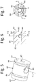
- the distribution body 80 comprises two transverse ducts 86 arranged along the transverse axes S and T, as shown in particular in figure 7 , wherein also the angle ⁇ is shown.
- the transverse ducts 86 of the distribution body are arranged along the same first S and second T transverse axes of the connectors 110 of the body 100 of the hydraulic operating device 10.
- the transverse ducts 86 are in fluid communication with the axial duct 85 and with the two respective connectors 110.
- the distribution body 80 is not made in one piece with the cartridge 40 so that should the angle ⁇ of the connectors 110 of the hydraulic operating device 10 changes, it is sufficient to replace only the distribution body 80 that has transverse ducts 86 arranged according to the same angle ⁇ as the connectors 110, it not being necessary to replace the cartridge 40, which is universal.
- a front plug 101 engages with the front opening 111 of the first chamber 11 so as to keep inside the hydraulic system fluid and the other elements of the hydraulic device 80, 70, 30, 40.
- the cartridge 40 provides engaging elements for the front plug 101.
- the front plug 101 comprises a through opening 113 adapted for the front part 33 of the piston 30 to pass through it to be pushed by the pressing portion 23 of the control lever 20.
- the hydraulic operating device 10 comprises a floating plug 90 which is slidably mounted inside the second chamber 12 of the hydraulic operating device 10 by means of two interlocking O-rings 93.
- the floating plug 90 is mounted inside the second chamber 12, making it pass through the rear opening 112.
- the further other elements of the hydraulic operating device 10 adapted to be inserted into the rear opening 112 of the second chamber 12 of the body 100 of the hydraulic operating device 10 are the floating plug 90, two interlocking O-rings 93, a sphere 95, a second elastic element 75, a rear O-ring 96 and a rear plug 102.
- the floating plug 90 comprises two seats 94 carved on its outer wall, wherein each of these two seats 94 is adapted to house one of the two interlocking O-rings 93, respectively.
- the seats 94 for the interlocking O-rings 93 are coaxial.
- the two seats 94 for the respective two interlocking O-rings 93 are a front seat 94 arranged respectively on a front part of the outer wall of the floating plug 90 and a rear seat 94 arranged respectively on a rear part of the outer wall of the floating plug 90, so that the floating plug 90 may slide inside the second chamber 12, keeping stopped the sliding axis, which is the second longitudinal axis M.
- the floating plug 90 comprises an axial through duct 91 carved inside the body of the floating plug 90 along the second longitudinal axis M.
- the axial through duct 91 is in fluid communication with the second chamber 12 and with the first channel 13 of the body 100 of the hydraulic operating device 10, and is in communication with the outside of the hydraulic operating device 10.
- the axial duct 91 comprises a cylindrical central part 912 that widens forwards forming a front part 911, wherein this front part 911 gradually widens its inner dimension to be better adapted to the inner dimensions and to the shape of the second chamber 12.
- the front part 911 of the axial duct 91 is in fluid communication with the second chamber 12.
- the rear verse of the central part 912 is in fluid communication with a part with an increased diameter 97 of the axial duct 91, wherein this part with an increased diameter 97 is adapted to provide a holding step 92 between the lower diameter of the central part 912 of the axial duct 91 and the part with an increased diameter 97.
- Such holding step 92 is adapted to serve as stop at a front end 76 of the second elastic element 75 of the floating plug 90.
- a rear end 77 of the second elastic element 75 is mounted with the sphere 95 of the floating plug 90.
- the sphere 95 is mounted in roto-translation with the axial duct 91.
- the part with an increased diameter 97 of the axial duct 91 has a diameter adapted to allow the rolling and/or the sliding of the sphere 95 inside it.
- the part with an increased diameter 97 of the axial duct 91 of the floating plug 90 is a housing for the sphere 95.
- the floating plug 90 comprises a rear opening 918 from which the second elastic element 75, the sphere 95, the rear O-ring 96 and the rear plug 102 can be inserted.
- the part with an increased diameter 97 of the axial duct 91 comprises a rear part that comprises six radial channels 910 arranged along radial directions that start from the centre of the axial duct 91 wherein there is the second longitudinal axis M, outwards of the floating plug 90.
- Such radial channels 910 gradually widen their cross section to directions parallel to the second longitudinal axis M.
- each radial channel 910 of the six radial channels 910 gradually widens a cross section of the radial channel 910 in a linear way and a longitudinal section of the radial channel 910 has a triangular shape.
- the cross section of the radial channels 910 has a geometric quadrangular shape.
- the part with an increased diameter 97 of the axial through duct 91 further widens with a second step 913 in a rear part 909 of the axial through duct 91, wherein the rear part 909 has a greater diameter than the part with an increased diameter 97 of the axial through duct 91.
- the rear part 909 of the axial through duct 91 comprises a front part 98 and a rear part 99 that comprise inner threaded walls which is the seat of the rear plug 102 that comprises outer threaded walls adapted to be screwed with the inner walls of the rear part 99 of the rear part 909 of the axial through duct 91.
- the rear plug 102 is a hollow cylinder comprising a rear through opening 103.
- the rear through opening 103 is carved inside the body of the rear plug 102 along the second longitudinal axis M.
- Inner walls of the rear plug 102 comprise a seat 104 for the rear O-ring 96 adapted to lock the sphere 95 between the rear plug 102 and the part with an increased diameter 97 of the axial through duct 91 of the floating plug 90.
- Inner walls of the rear plug 102 comprise an inner wall 105 that reduces the inner diameter of the rear through opening 103 of the rear plug 102.
- the rear plug 102 is mounted with said axial through duct 91 and is adapted to retain the sphere 95 inside the axial through duct 91.
- the inner wall 105 prevents the sphere 95 from coming out through the rear through opening 103 of the rear plug 102, retaining the sphere 96 inside the axial through duct 91.
- the rear O-ring 96 is mounted with the sphere 95 and is pressed by the sphere 95 which in turn is pressed by the second elastic element 75 against the inner wall 105 of the rear plug 102, serving as sealing gasket to avoid the fluid of the second chamber 12 from exiting outwards.
- the sphere 95 is adapted to make the second elastic element 75 switch from at least a compressed position to at least a more compressed position, wherein the compressed position of the second elastic element 75 provides for the sphere 95 to push the rear O-ring 96 to lock the fluid from coming out of the axial through duct 91, while the more compressed position of the second elastic element 75 allows the sphere 95 to roto-translate and allows the fluid to come out of the axial through duct 91.
- the control lever 20 rotates about the pin 25 and the pressing portion 23 pushes the front part 33 of the piston 30 towards the inside of the first chamber 11, making the piston 30 slide inside the inner walls of the cartridge 40 in conformity with the rotation of the control lever 20.
- the hydraulic system fluid is ejected from the first chamber 11 through the axial duct 85 of the distribution body 80, passing through the two transverse ducts 86 of the distribution body 80 towards the hydraulic system to control the brake caliper.
- a grub screw pushes the sphere 95, compressing the second elastic element 75 until the rear through opening 103 is in fluid communication with the axial duct 91 to clean the fluid present in the second chamber 12 or to fill the second chamber 12 with the fluid from the rear through opening 103.
- the grub screw stops compressing the sphere 95, it is pushed into the initial position against the inner wall 105 of the rear plug 102 by the elastic force of the second elastic element 75 of the floating plug 90, keeping the second chamber 12 closed.
- the floating plug 90 is adapted to slide inside the second chamber 12 so as to keep the floating plug 90 under pressure against the fluid present inside the second chamber 12 also when the quantity of fluid, and therefore the volume of fluid of the second chamber 12 decreases following the use of the hydraulic operating device 10, and more generally, of the hydraulic system of the cycle or motorcycle brake or of the clutch of the motorcycle. Measuring the position of the floating plug 90 with respect to the body 100 of the hydraulic operating device 10, it is possible to establish the level of fluid present in the second chamber 12.
- the floating plug 90 adheres with the inner wall of the second chamber 12 and being slidably mounted with this inner wall of the second chamber 12 by means of the O-rings 93, it may translate along the second longitudinal axis M, dragged by the changes of volume of the fluid inside the second chamber 12 caused by the introduction of the fluid.
- a grub screw 114 shown in figure 3 , adapted to make the floating plug 90 slide towards the front or towards the back of the second chamber 12.
- the hydraulic operating device 10 it is possible to provide for the hydraulic operating device 10 to be for a hydraulic system fluid of a clutch of a motorcycle.
- the cartridge 40 is made in one piece with the body of the hydraulic operating device 10.
- this alternative provides for the cartridge 40 not to be required, rather for it to have a different spatial arrangement of the connectors 110 in the presence of a different hydraulic operating device 10, which is sufficient to replace the distribution body 80 alone with another one comprising transverse ducts 86 reproducing the spatial arrangement of the connectors 110 of the hydraulic operating device 10.
- the connectors 110 it is possible to provide for the connectors 110 not to lie on the same geometric plane, rather to be arranged according to any spatial distribution. In such alternative, it is sufficient to replace the distribution body 80 alone with one that comprises transverse ducts 86 that reproduce the different spatial arrangement of the connectors 110 of the hydraulic operating device 10.
- sealing elements 83, 93, 96 may be provided in place of the O-rings 83, 93, 96.
Landscapes
- Engineering & Computer Science (AREA)
- Mechanical Engineering (AREA)
- General Engineering & Computer Science (AREA)
- Physics & Mathematics (AREA)
- Fluid Mechanics (AREA)
- Transportation (AREA)
- Transmission Of Braking Force In Braking Systems (AREA)
- Actuator (AREA)
- Auxiliary Drives, Propulsion Controls, And Safety Devices (AREA)
Description
- The present invention relates to a hydraulic operating device for a cycle or for a motorcycle comprising a float valve.
- Hydraulic operating devices for hydraulic bicycle brakes or for a motorcycle clutch are known in the state of the art.
- For example, a hydraulic braking system for a bicycle comprises a brake caliper and a hydraulic operating device for brakes that comprises a brake lever adapted to rotate about a pin, a piston that slides in a main cylinder of a cartridge in conformity with the rotation of the brake lever. When the piston slides, the fluid (oil, for example) is ejected from the main cylinder to control the brake caliper
- A hydraulic operating device for a hydraulic brake system with a floating plug in a second chamber for replenishing the primary pressure chamber, is known from German Patent
DE 872 455 C1 . - It is the object of the present invention to make a hydraulic operating device that is easy to fill with a hydraulic system fluid and is easy to clean, which allows detecting a quantity of fluid present in a tank-chamber.
- According to the invention, this object is achieved by a hydraulic operating device according to claim 1.
- Other features are provided in the dependent claims.
- The features and advantages of the present invention will be more apparent from the following description, which is to be understood as exemplifying and not limiting, with reference to the appended schematic drawings, wherein:
-
figure 1 is an exploded perspective view of a hydraulic operating device for a cycle or for a motorcycle according to the present invention; -
figure 2 is a side view of the hydraulic operating device; -
figure 3 is a rear view of the hydraulic operating device; -
figure 4 is a section view according to the line IV-IV offigure 3 ; -
figure 5 is a perspective view of a float valve of the hydraulic operating device; -
figure 6 shows a section view of the float valve offigure 5 , according to the line IV-IV offigure 3 ; -
figure 7 shows a section view of the float valve according to the line VII-VII offigure 6 ; -
figure 8 shows a perspective view of a distribution body of hydraulic fluid of the hydraulic operating device; -
figure 9 shows a section view of the distribution body offigure 8 , according to the line IV-IV offigure 3 ; -
figure 10 shows a rear view of the distribution body. - With reference to the mentioned drawings, a
hydraulic operating device 10 for a hydraulic system fluid of a cycle or of a motorcycle is shown;figures 1 to 10 in particular show ahydraulic operating device 10 for a hydraulic system fluid for a bicycle brake. Thehydraulic operating device 10 acts as actuator of brake calipers. - As shown in particular in
figure 4 , thehydraulic operating device 10 comprises afirst chamber 11 and asecond chamber 12 which are in fluid communication by means of afirst channel 13. - The
first chamber 11 and thesecond chamber 12 are carved in abody 100 of thehydraulic operating device 10. - The
first channel 13 is carved in thebody 100 between the first 11 and thesecond chamber 12. - The
first chamber 11 comprises a longitudinal dimension carved in thebody 100 along a first longitudinal axis L. - The
second chamber 12 comprises a longitudinal dimension carved in thebody 100 along a second longitudinal axis M. - The first longitudinal axis L and the second longitudinal axis L are parallel to each other so as to advantageously reduce the dimensions of the
hydraulic operating device 10. - The
first chamber 11 is enclosed by walls of thebody 100 that are cylindrical in shape. - As shown in particular in
figures 1 to 4 , thefirst chamber 11 is closed at the back by means of arear wall 118 of thebody 100 and is open at the front by means of a front opening 111 of thebody 100. - The
front opening 111 has dimensions adapted for the insertion of other elements of thehydraulic operating device 10. - The
second chamber 12 is enclosed by walls of thebody 100. - The
second chamber 12 is closed at the front by means of afront wall 128 of thebody 100 and is open at the back by means of arear opening 112 of thebody 100. Therear opening 112 has dimensions adapted for the insertion of further other elements of thehydraulic operating device 10. - The
second chamber 12 is a tank for the hydraulic system fluid. - The
first channel 13 is carved in the body along a transverse direction which is perpendicular both to the first longitudinal axis L and to the second longitudinal axis M. - The
body 100 of thehydraulic operating device 10 comprises twoconnectors 110 that are through openings that put the outside of thebody 100 in fluid communication with thefirst chamber 11 and that are adapted to mountrespective connectors 200 of the hydraulic system. Theconnectors 110 of thebody 100 are adapted to make the hydraulic system fluid exiting from thefirst chamber 11 or entering thefirst chamber 11 pass through them. - As shown in particular in
figure 3 , the twoconnectors 110 are carved in thebody 100 along two different transverse directions arranged along two respective transverse axes S and T. The two transverse axes S and T are perpendicular to the first L and to the second M longitudinal axis L. The two transverse axes S and T lie on a transverse geometric plane perpendicular to the longitudinal axes L and M, wherein an angle θ is shown between a first transverse axis S and a second transverse axis T of the two transverse axes. - The angle θ between the first transverse axis S and the second transverse axis S is comprised between 0 and 360 sexagesimal degrees. The
hydraulic operating device 10 may indeed providedifferent connectors 110 arranged at different angles θ with respect to the ones shown in particular infigure 3 . For example, when the angle θ is of 0 sexagesimal degrees, then oneconnector 110 alone, arranged towards the bottom with respect tofigure 3 , is provided in place of the twoconnectors 110. For example, when the angle θ is of 360 sexagesimal degrees, then oneconnector 100 alone, arranged towards the top with respect tofigure 3 , is provided in place of the twoconnectors 110. - As shown in particular in
figures 1 to 4 , thebody 100 of thehydraulic operating device 10 comprises aslotted portion 14 comprising two throughslots 15. The slottedportion 14 is arranged in the upper front part of thebody 100 of thehydraulic operating device 10. - The
hydraulic operating device 10 comprises acontrol lever 20 and apin 25, wherein thecontrol lever 20 is rotatably mounted by means of thepin 25 with the two throughslots 15 of the slottedportion 14 of thebody 100. - The
hydraulic operating device 10 comprises the other elements of thehydraulic operating device 10 adapted to be inserted inside thefirst chamber 11. The other elements of thehydraulic operating device 10 are adistribution body 80 of the hydraulic system fluid, acartridge 40, a firstelastic element 70 and apiston 30. - The
distribution body 80, thecartridge 40, the firstelastic element 70 and thepiston 30 are mounted inside thefirst chamber 11 of thehydraulic operating device 10 along the direction of the first longitudinal axis L, making them pass in sequence through the front throughopening 111 of thebody 100. - As shown in particular in
figure 4 , thefirst chamber 11 comprises arear part 17 and afront part 19. Therear part 17 of thefirst chamber 11 has a smaller diameter with respect to thefront part 19. - The
rear part 17 of thefirst chamber 11 is adapted to allow the sealable insertion of thedistribution body 80 until arear wall 82 of thedistribution body 80 is stopped in contact with therear wall 118 of thebody 100. - The
second part 19 of thefirst chamber 11 is adapted to allow the insertion of thecartridge 40. - A
step 24 is formed between thefirst part 17 and thesecond part 19 of thefirst chamber 11, which step is adapted to act as a stop for an open rear end in the rear through opening 44 of thecartridge 40. - The
first part 17 of thefirst chamber 11 comprises the twoconnectors 110 for the hydraulic system fluid. - As shown in particular in
figures 1 ,4 , thecartridge 40 is a hollow cylinder comprising a front throughopening 46 and the rear throughopening 44. - The
cartridge 40 comprises an outer surface comprising afirst groove 43 that decreases the outer diameter of the outer surface of thecartridge 40. A first through opening 41 and a second throughopening 42 are carved in the body of thecartridge 40, starting from thefirst groove 43 up to reaching the inner surface of thecartridge 40. - The inner part of the
hollow cartridge 40 identifies acavity 47 of thecartridge 40. - The
first groove 43 of thecartridge 40 is arranged at thefirst channel 13 of thebody 100. - The
first groove 43 of thecartridge 40 is in fluid communication with thefirst channel 13 of thebody 100. - The first through opening 41 and the second through
opening 42 are in fluid communication with thefirst channel 13 of thebody 100 and are adapted to make the fluid pass between thefirst groove 43 and the inner surface of thecartridge 40. - The first through opening 41 and the second through
opening 43 are carved in the body of thecartridge 40 along transverse axes that are perpendicular to the first longitudinal axis L. - As shown in particular in
figures 1 ,2 ,4 , thehydraulic operating device 10 also comprises a stoppinggrub screw 46. - The
cartridge 40 comprises asecond groove 45 adapted to be engaged by the stoppinggrub screw 46 that engages in a through opening 16 in the body of thehydraulic operating device 10 to lock thecartridge 40 inside thefirst chamber 11, thus preventing it from sliding inside thefront part 19 of thefirst chamber 11, therefore locking thecartridge 40 with thebody 100. - The
cavity 47 of thecartridge 40 is adapted to allow the sliding of thepiston 30 and the compression and relaxation movement of the firstelastic element 70. - The front through opening 46 of the
cartridge 40 has suitable dimensions for the insertion of the firstelastic element 70 and of thepiston 30. - The
control lever 20 comprises apressing portion 23 that is adapted to switch from a multiplicity of positions during the rotation of thecontrol lever 20 about thepin 25. Thepressing portion 23 of thecontrol lever 20 is adapted to push afront part 33 of thepiston 30 of thehydraulic operating device 10 inside thefront part 19 of thefirst chamber 11 along the direction of the first longitudinal axis L and towards therear wall 118 of thebody 100. - The
piston 30 is slidably mounted with saidcavity 47 of thecartridge 40 and is adapted to make the firstelastic element 70 switch from at least one compressed position to at least one more compressed position. Thepiston 30 comprises thefront part 33 facing towards thefront opening 111 of thebody 100 and a rear part comprising astem 31 that mounts afront end 71 of the firstelastic element 70. - A
rear end 72 of the firstelastic element 70 is mounted against afront wall 81 of thedistribution body 80. - The first
elastic element 70 is a helical spring. Other types of elastic elements may also be provided. - As shown in particular in
figures 1 ,4 to 7 , thedistribution body 80 has the shape of a cylinder and is mounted inside therear part 17 of thefirst chamber 11 of thehydraulic operating device 10 by means of two O-rings 83, and therear wall 82 of thedistribution body 80 is in contact with therear wall 118 of thebody 100. - The
distribution body 80 comprises twoseats 84 carved on its outer wall, wherein each of these twoseats 84 is adapted to house one of the two O-rings 83, respectively. Theseats 84 for the O-rings 83 are coaxial. Once the two O-rings 83 are mounted in the tworespective seats 84 of thedistribution body 80, thedistribution body 80 is mounted with therear part 17 of thefirst chamber 11 so that the two O-rings 83 interlock thedistribution body 80 with the inner walls of therear part 17 of thefirst chamber 11. - The
distribution body 80 comprises anaxial duct 85 carved inside thedistribution body 80 along the first longitudinal axis L. Theaxial duct 85 is in fluid communication with thefirst chamber 11 and with thecavity 47 of thecartridge 40. - The
distribution body 80 comprises twotransverse ducts 86 arranged along the transverse axes S and T, as shown in particular infigure 7 , wherein also the angle θ is shown. Thetransverse ducts 86 of the distribution body are arranged along the same first S and second T transverse axes of theconnectors 110 of thebody 100 of thehydraulic operating device 10. - The
transverse ducts 86 are in fluid communication with theaxial duct 85 and with the tworespective connectors 110. - Advantageously, the
distribution body 80 is not made in one piece with thecartridge 40 so that should the angle θ of theconnectors 110 of thehydraulic operating device 10 changes, it is sufficient to replace only thedistribution body 80 that hastransverse ducts 86 arranged according to the same angle θ as theconnectors 110, it not being necessary to replace thecartridge 40, which is universal. - As shown in particular in
figures 1 and4 , afront plug 101 engages with thefront opening 111 of thefirst chamber 11 so as to keep inside the hydraulic system fluid and the other elements of thehydraulic device - In particular as shown in
figure 4 , thecartridge 40 provides engaging elements for thefront plug 101. - The
front plug 101 comprises a throughopening 113 adapted for thefront part 33 of thepiston 30 to pass through it to be pushed by thepressing portion 23 of thecontrol lever 20. - As shown in particular in
figures 1 ,8 to 10 , thehydraulic operating device 10 comprises a floatingplug 90 which is slidably mounted inside thesecond chamber 12 of thehydraulic operating device 10 by means of two interlocking O-rings 93. The floatingplug 90 is mounted inside thesecond chamber 12, making it pass through therear opening 112. - The further other elements of the
hydraulic operating device 10 adapted to be inserted into therear opening 112 of thesecond chamber 12 of thebody 100 of thehydraulic operating device 10 are the floatingplug 90, two interlocking O-rings 93, asphere 95, a secondelastic element 75, a rear O-ring 96 and arear plug 102. - The floating
plug 90 comprises twoseats 94 carved on its outer wall, wherein each of these twoseats 94 is adapted to house one of the two interlocking O-rings 93, respectively. Theseats 94 for the interlocking O-rings 93 are coaxial. Once the two interlocking O-rings 93 are mounted in the tworespective seats 94 of the floatingplug 90, the floatingplug 90 is slidably mounted with the inner walls of thesecond chamber 12 so that the two interlocking O-rings 93 interlock the floatingplug 90 with the inner walls of thesecond chamber 12. - The two
seats 94 for the respective two interlocking O-rings 93 are afront seat 94 arranged respectively on a front part of the outer wall of the floatingplug 90 and arear seat 94 arranged respectively on a rear part of the outer wall of the floatingplug 90, so that the floatingplug 90 may slide inside thesecond chamber 12, keeping stopped the sliding axis, which is the second longitudinal axis M. - The floating
plug 90 comprises an axial throughduct 91 carved inside the body of the floatingplug 90 along the second longitudinal axis M. The axial throughduct 91 is in fluid communication with thesecond chamber 12 and with thefirst channel 13 of thebody 100 of thehydraulic operating device 10, and is in communication with the outside of thehydraulic operating device 10. - The
axial duct 91 comprises a cylindricalcentral part 912 that widens forwards forming afront part 911, wherein thisfront part 911 gradually widens its inner dimension to be better adapted to the inner dimensions and to the shape of thesecond chamber 12. Thefront part 911 of theaxial duct 91 is in fluid communication with thesecond chamber 12. - The rear verse of the
central part 912 is in fluid communication with a part with an increaseddiameter 97 of theaxial duct 91, wherein this part with an increaseddiameter 97 is adapted to provide a holdingstep 92 between the lower diameter of thecentral part 912 of theaxial duct 91 and the part with an increaseddiameter 97. Such holdingstep 92 is adapted to serve as stop at afront end 76 of the secondelastic element 75 of the floatingplug 90. Arear end 77 of the secondelastic element 75 is mounted with thesphere 95 of the floatingplug 90. - The
sphere 95 is mounted in roto-translation with theaxial duct 91. The part with an increaseddiameter 97 of theaxial duct 91 has a diameter adapted to allow the rolling and/or the sliding of thesphere 95 inside it. The part with an increaseddiameter 97 of theaxial duct 91 of the floatingplug 90 is a housing for thesphere 95. - The floating
plug 90 comprises arear opening 918 from which the secondelastic element 75, thesphere 95, the rear O-ring 96 and therear plug 102 can be inserted. - The part with an increased
diameter 97 of theaxial duct 91 comprises a rear part that comprises sixradial channels 910 arranged along radial directions that start from the centre of theaxial duct 91 wherein there is the second longitudinal axis M, outwards of the floatingplug 90. Suchradial channels 910 gradually widen their cross section to directions parallel to the second longitudinal axis M. - In particular as shown in
figure 9 , eachradial channel 910 of the sixradial channels 910 gradually widens a cross section of theradial channel 910 in a linear way and a longitudinal section of theradial channel 910 has a triangular shape. - As shown instead in
figure 10 , the cross section of theradial channels 910 has a geometric quadrangular shape. - As shown in particular in
figure 9 , the part with an increaseddiameter 97 of the axial throughduct 91 further widens with asecond step 913 in arear part 909 of the axial throughduct 91, wherein therear part 909 has a greater diameter than the part with an increaseddiameter 97 of the axial throughduct 91. - The
rear part 909 of the axial throughduct 91 comprises afront part 98 and arear part 99 that comprise inner threaded walls which is the seat of therear plug 102 that comprises outer threaded walls adapted to be screwed with the inner walls of therear part 99 of therear part 909 of the axial throughduct 91. - As shown in particular in
figure 4 , therear plug 102 is a hollow cylinder comprising a rear throughopening 103. The rear throughopening 103 is carved inside the body of therear plug 102 along the second longitudinal axis M. Inner walls of therear plug 102 comprise aseat 104 for the rear O-ring 96 adapted to lock thesphere 95 between therear plug 102 and the part with an increaseddiameter 97 of the axial throughduct 91 of the floatingplug 90. Inner walls of therear plug 102 comprise aninner wall 105 that reduces the inner diameter of the rear through opening 103 of therear plug 102. - The
rear plug 102 is mounted with said axial throughduct 91 and is adapted to retain thesphere 95 inside the axial throughduct 91. In particular, theinner wall 105 prevents thesphere 95 from coming out through the rear through opening 103 of therear plug 102, retaining thesphere 96 inside the axial throughduct 91. - The rear O-
ring 96 is mounted with thesphere 95 and is pressed by thesphere 95 which in turn is pressed by the secondelastic element 75 against theinner wall 105 of therear plug 102, serving as sealing gasket to avoid the fluid of thesecond chamber 12 from exiting outwards. - The
sphere 95 is adapted to make the secondelastic element 75 switch from at least a compressed position to at least a more compressed position, wherein the compressed position of the secondelastic element 75 provides for thesphere 95 to push the rear O-ring 96 to lock the fluid from coming out of the axial throughduct 91, while the more compressed position of the secondelastic element 75 allows thesphere 95 to roto-translate and allows the fluid to come out of the axial throughduct 91. - Concerning the operation of the
hydraulic operating device 10, thecontrol lever 20 rotates about thepin 25 and thepressing portion 23 pushes thefront part 33 of thepiston 30 towards the inside of thefirst chamber 11, making thepiston 30 slide inside the inner walls of thecartridge 40 in conformity with the rotation of thecontrol lever 20. When thepiston 30 slides, the hydraulic system fluid is ejected from thefirst chamber 11 through theaxial duct 85 of thedistribution body 80, passing through the twotransverse ducts 86 of thedistribution body 80 towards the hydraulic system to control the brake caliper. - When the
control lever 20 does not push on thefront part 33 of thepiston 30, thepiston 30 is pushed into the initial position by the firstelastic element 70 and the hydraulic system fluid goes back into thefirst chamber 11 or arrives from thesecond chamber 12 by means of thefirst channel 13. - Concerning a filling or cleaning of fluid, a grub screw (not shown in the figures) pushes the
sphere 95, compressing the secondelastic element 75 until the rear throughopening 103 is in fluid communication with theaxial duct 91 to clean the fluid present in thesecond chamber 12 or to fill thesecond chamber 12 with the fluid from the rear throughopening 103. When the grub screw stops compressing thesphere 95, it is pushed into the initial position against theinner wall 105 of therear plug 102 by the elastic force of the secondelastic element 75 of the floatingplug 90, keeping thesecond chamber 12 closed. - Concerning a verification of the level of fluid present in the
second chamber 12, the floatingplug 90 is adapted to slide inside thesecond chamber 12 so as to keep the floatingplug 90 under pressure against the fluid present inside thesecond chamber 12 also when the quantity of fluid, and therefore the volume of fluid of thesecond chamber 12 decreases following the use of thehydraulic operating device 10, and more generally, of the hydraulic system of the cycle or motorcycle brake or of the clutch of the motorcycle. Measuring the position of the floatingplug 90 with respect to thebody 100 of thehydraulic operating device 10, it is possible to establish the level of fluid present in thesecond chamber 12. The floatingplug 90 adheres with the inner wall of thesecond chamber 12 and being slidably mounted with this inner wall of thesecond chamber 12 by means of the O-rings 93, it may translate along the second longitudinal axis M, dragged by the changes of volume of the fluid inside thesecond chamber 12 caused by the introduction of the fluid. - Alternatively, there is also provided a
grub screw 114, shown infigure 3 , adapted to make the floatingplug 90 slide towards the front or towards the back of thesecond chamber 12. - Alternatively, it is possible to provide for the
hydraulic operating device 10 to be for a hydraulic system fluid of a clutch of a motorcycle. - Alternatively, the
cartridge 40 is made in one piece with the body of thehydraulic operating device 10. Advantageously, this alternative provides for thecartridge 40 not to be required, rather for it to have a different spatial arrangement of theconnectors 110 in the presence of a differenthydraulic operating device 10, which is sufficient to replace thedistribution body 80 alone with another one comprisingtransverse ducts 86 reproducing the spatial arrangement of theconnectors 110 of thehydraulic operating device 10. - Alternatively, it is possible to provide for the
connectors 110 not to lie on the same geometric plane, rather to be arranged according to any spatial distribution. In such alternative, it is sufficient to replace thedistribution body 80 alone with one that comprisestransverse ducts 86 that reproduce the different spatial arrangement of theconnectors 110 of thehydraulic operating device 10. - Alternatively, it is possible for sealing
elements rings - The invention thus conceived is susceptible to many modifications and variants, all falling within the same inventive concept; furthermore, all details can be replaced by equivalent technical elements. In practice, the materials used, as well as the dimensions thereof, can be of any type according to the technical requirements.
Claims (17)
- A hydraulic operating device (10) for a fluid of a cycle or of a motorcycle hydraulic system comprising a body (100), a first chamber (11) carved in the body (100) adapted for housing an actuating piston (30), a second tank-chamber (12) carved in the body (100) and in fluid communication with said first chamber (11), a floating plug (90), a sphere (95), an elastic element (75), a rear sealing element (96) and a rear plug (102),
said second chamber (12) is adapted for housing said floating plug (90),
characterised in that said second chamber (12) is enclosed by the body walls (100) and open outwards through a rear opening (112) of the body (100),
said rear opening (112) of the body (100) has dimensions adapted for the insertion of said floating plug (90),
said floating plug (90) is slidably mounted inside the second chamber (12),
said floating plug (90) comprises an axial through duct (91) in fluid communication with the second chamber (12),
said sphere (95) is mounted in rototranslating way inside the axial through duct (91),
said rear plug (102) comprises a rear through opening (103) in fluid communication with the axial duct (91) and with the outside,
said rear plug (102) is mounted with said axial through duct (91),
said elastic element (75) is mounted inside said axial through duct (91),
said rear sealing element (96) is mounted with the sphere (95),
said sphere (95) is adapted to make said elastic element (75) pass from at least one compressed position to at least a more compressed position,
wherein the compressed position of the elastic element (75) provides that the sphere (95) pushes said rear sealing element (96) to stop the fluid from coming out the axial through duct (91),
wherein the more compressed position of the elastic element (75) allows the sphere (95) to roto-translate allowing the fluid to come out the axial through duct (91) . - Hydraulic operating device (10) according to claim 1, characterised in that it comprises at least one interlocking sealing element (93),
wherein said floating plug (90) comprises at least one seat (94) carved on its outer wall and adapted for housing at least one interlocking sealing element (93) of the hydraulic operating device (10), said at least one sealing element (93) being mounted with said at least one seat (94) of the floating plug (90). - Hydraulic operating device (10) according to claim 2, characterised in that said floating plug (90) comprises two seats (94) of said at least one seat (94) that are respectively mounted with two interlocking sealing elements (93) of said at least one interlocking sealing element (93).
- Hydraulic operating device (10) according to any one of claims from 1 to 3, characterised in that the compressed position of the elastic element (75) requires the sphere (95) to push said rear sealing element (96) against said rear plug (102).
- Hydraulic operating device (10) according to any one of claims from 1 to 4, characterised in that said rear plug (102) is mounted with said axial through duct (91) and is adapted for retaining the sphere (95) inside the axial through duct (91).
- Hydraulic operating device (10) according to claim 5, characterised in that an inner wall of the rear through opening (103) of the rear plug (102) comprises an inner wall (105) that reduces the inner diameter of the rear through opening (103) of the rear plug (102), retaining the sphere (95) inside the axial through duct (91) .
- Hydraulic operating device (10) according to claim 6, characterised in that the compressed position of the elastic element (75) requires the sphere (95) to push said rear sealing element (96) against said inner wall (105) of said rear plug (102).
- Hydraulic operating device (10) according to any one of claims from 1 to 7, characterised in that the inner walls of the rear plug (102) comprise a seat (104) where said rear sealing element (96) is mounted, locking the sphere (95) inside the axial through duct (91) of the floating plug (90).
- Hydraulic operating device (10) according to any one of claims from 1 to 8, characterised in that said floating plug (90) comprises a rear opening (918) of dimensions adapted for allowing the insertion of the elastic element (75), the sphere (95), the rear sealing element (96) and the rear plug (102).
- Hydraulic operating device (10) according to any one of claims from 1 to 9, characterised in that said axial through duct (91) of the floating plug (90) comprises a cylindrical central part (912) that widens forwards forming a front part (911), wherein said front part (911) gradually widens its inner size adapting to the inner dimensions and to the shape of the second chamber (12), wherein said front part (911) of the axial through duct (91) is in fluid communication with the second chamber (12).
- Hydraulic operating device (10) according to any one of claims from 1 to 10, characterised in that said axial through duct (91) of the floating plug (90) comprises a part with an increased diameter (97), wherein said part with an increased diameter (97) houses said sphere (95).
- Hydraulic operating device (10) according to claim 11, characterised in that the part with an increased diameter (97) of the axial through duct (91) comprises a rear part with a plurality of radial channels (910) arranged following radial directions that stretch from the centre of the axial through duct (91) towards the outer part of the floating plug (90) gradually widening their cross section.
- Hydraulic operating device (10) according to claim 11, characterised in that each radial channel (910) of said plurality of radial channels (910) gradually widens a cross section of the radial channel (910) in a linear way and a longitudinal section of the radial channel (910) has a triangular shape.
- Hydraulic operating device (10) according to any one of claims from 11 to 13, characterised in that said central part (912) of the axial through duct (91) is in fluid communication with said part with an increased diameter (97) of the axial through duct (91), wherein this part with an increased diameter (97) provides a holding step (92) between the lower diameter of the central part (912) of the axial through duct (91) and the part with an increased diameter (97) of the axial through duct (91), wherein said holding step (92) is adapted to be used as a stop for a front end (76) of the elastic element (75) and a rear end (77) of the elastic element (75) is mounted with the sphere (95).
- Hydraulic operating device (10) according to any one of claims from 11 to 14, characterised in that the part with an increased diameter (97) of the axial through duct (91) widens with a second step (913) into a rear part (909) of the axial through duct (91), wherein the diameter of said rear part (909) is greater than that of the part with an increased diameter (97) of the axial through duct (91), wherein said rear part (909) of the axial through duct (91) comprises inner threaded walls serving as a seat of the rear plug (102) that comprises outer threaded walls adapted to be screwed onto said inner walls of the rear part (909) of the axial through duct (91).
- Hydraulic operating device (10) according to any one of claims from 1 to 15, characterised in that said second chamber (12) comprises a longitudinal dimension carved in the body (100) along a second longitudinal axis (M) and in that said axial through duct (91) of said floating plug (90) is carved inside the body of the floating plug (90) along said second longitudinal axis (M) and in that said rear through opening (103) of the rear plug (102) is carved inside the body of the rear plug (102) along said second longitudinal axis (M).
- Hydraulic operating device (10) according to claim 16, characterised in that said first chamber (11) comprises a longitudinal dimension carved in the body (100) along a first longitudinal axis (L) and in that said first longitudinal axis (L) is parallel to said second longitudinal axis (M).
Applications Claiming Priority (1)
| Application Number | Priority Date | Filing Date | Title |
|---|---|---|---|
| IT102018000008058A IT201800008058A1 (en) | 2018-08-10 | 2018-08-10 | HYDRAULIC DRIVE DEVICE FOR A MOTORCYCLE INCLUDING A FLOAT VALVE. |
Publications (2)
| Publication Number | Publication Date |
|---|---|
| EP3608182A1 EP3608182A1 (en) | 2020-02-12 |
| EP3608182B1 true EP3608182B1 (en) | 2021-05-26 |
Family
ID=64049600
Family Applications (1)
| Application Number | Title | Priority Date | Filing Date |
|---|---|---|---|
| EP19190985.2A Active EP3608182B1 (en) | 2018-08-10 | 2019-08-09 | Hydraulic operating device for a cycle or for a motorcycle comprising a float valve |
Country Status (4)
| Country | Link |
|---|---|
| US (1) | US11009049B2 (en) |
| EP (1) | EP3608182B1 (en) |
| IT (1) | IT201800008058A1 (en) |
| TW (1) | TWI826499B (en) |
Families Citing this family (1)
| Publication number | Priority date | Publication date | Assignee | Title |
|---|---|---|---|---|
| US12037076B1 (en) * | 2023-03-09 | 2024-07-16 | Shimano Inc. | Hydraulic reservoir and operating device of human-powered vehicle |
Family Cites Families (32)
| Publication number | Priority date | Publication date | Assignee | Title |
|---|---|---|---|---|
| DE666461C (en) * | 1935-07-01 | 1938-10-20 | Hermann Kurt Weihe | Fluid braking device, in particular for motor vehicles |
| DE670875C (en) | 1935-08-06 | 1939-01-26 | Giovanni Farina | Pressure cylinder of a fluid brake for motor vehicles |
| US2112356A (en) * | 1935-12-14 | 1938-03-29 | Hydraulic Brake Co | Fluid pressure producing device |
| FR906353A (en) * | 1941-06-13 | 1946-01-04 | Teves Gmbh Alfred | Hydraulic pressure device |
| DE740084C (en) * | 1941-07-11 | 1943-10-11 | Teves Kg Alfred | Master cylinder, especially for hydraulic braking devices in motor vehicles |
| DE893449C (en) * | 1942-06-11 | 1953-10-15 | Auto Union A G | Method and device for charging and actuating hydraulic vehicle brakes |
| DE872455C (en) * | 1942-06-20 | 1953-04-02 | Auto Union A G | Method and device for venting, charging and actuating hydraulic vehicle brakes |
| GB562073A (en) | 1943-02-11 | 1944-06-16 | Automotive Prod Co Ltd | Improvements in or relating to fluid pressure cylinders, particularly for hydraulic jacks |
| BE493682A (en) * | 1949-02-09 | |||
| US3474710A (en) | 1967-09-01 | 1969-10-28 | Air Mite Devices Inc | Cylinder construction using roll pins |
| US3643551A (en) | 1970-08-07 | 1972-02-22 | Allis Chalmers Mfg Co | Hydraulic cylinder |
| US3913619A (en) * | 1974-03-01 | 1975-10-21 | Sr Marvin J Aulner | Hydraulic system air bleeder valve assembly with antivibration spring retainer |
| US4149559A (en) * | 1976-05-21 | 1979-04-17 | Wingaersheek, Inc. | Pressure regulator |
| US4211150A (en) | 1977-10-26 | 1980-07-08 | Abex Corporation | Air cylinder |
| US4319671A (en) * | 1980-06-02 | 1982-03-16 | Wabco, Ltd. | Hydro-pneumatic brake actuator arranged to maintain a constant brake shoe clearance |
| US4524800A (en) * | 1984-05-14 | 1985-06-25 | Robert E. Robbins | One-way brake bleeder check valve with sealing cap |
| US4802559A (en) * | 1988-02-03 | 1989-02-07 | American Standard Inc. | Hydropneumatic brake actuator arranged to maintain a constant brake shoe clearance |
| US4949590A (en) * | 1988-02-17 | 1990-08-21 | Automotive Products Plc | Hydraulic cylinder assembly |
| US4989639A (en) * | 1988-05-09 | 1991-02-05 | Sulwer Michael T | Brake bleeder check valve |
| US4878419A (en) | 1988-06-27 | 1989-11-07 | Allied-Signal Inc. | Lightweight hydraulic actuator |
| DE4400483C2 (en) | 1994-01-11 | 1996-12-19 | Invest Tech Ag | Linear drive cylinder |
| AU2012899A (en) * | 1997-12-23 | 1999-07-12 | Kelsey-Hayes Company | Vehicular brake system with vehicle stability control having evacuation valve |
| US6014862A (en) * | 1998-03-26 | 2000-01-18 | General Motors Corporation | Emulator damping mechanism |
| JP2000335396A (en) * | 1999-03-19 | 2000-12-05 | Honda Motor Co Ltd | Master cylinder for brake |
| EP1435315B1 (en) | 2003-01-06 | 2006-11-22 | Nissin Kogyo Co., Ltd. | Hydraulic master cylinder for vehicle |
| JP2005162126A (en) | 2003-12-05 | 2005-06-23 | Nissin Kogyo Co Ltd | Brake device for vehicle |
| DE102005028645A1 (en) * | 2005-06-20 | 2007-01-04 | Martin Maszull | Bleed screw with check valve |
| DE102006060048A1 (en) * | 2006-12-19 | 2008-08-21 | B2-Pirol Gmbh & Co.Kg | Brake armature for manually operated hydraulic brake system of e.g. motorcycle, has compression area staying in fluid connection with hollow chamber system that receives brake fluid over fluid line |
| US20090152063A1 (en) * | 2007-12-13 | 2009-06-18 | Szu-Fang Tsai | Pumping device for a hydraulic brake of a bicycle |
| US8904782B2 (en) | 2010-10-12 | 2014-12-09 | Hb Performance Systems, Inc. | Hydraulic brake master cylinder with back-up ring |
| CN201989779U (en) * | 2011-01-24 | 2011-09-28 | 宁波市鄞州瑞波机械有限公司 | Master cylinder of hydraulic brake |
| KR102006833B1 (en) * | 2014-10-23 | 2019-10-08 | 주식회사 만도 | Master cylinder for brake system |
-
2018
- 2018-08-10 IT IT102018000008058A patent/IT201800008058A1/en unknown
-
2019
- 2019-08-08 TW TW108128264A patent/TWI826499B/en active
- 2019-08-09 EP EP19190985.2A patent/EP3608182B1/en active Active
- 2019-08-09 US US16/536,405 patent/US11009049B2/en active Active
Also Published As
| Publication number | Publication date |
|---|---|
| US11009049B2 (en) | 2021-05-18 |
| US20200049171A1 (en) | 2020-02-13 |
| EP3608182A1 (en) | 2020-02-12 |
| TW202009161A (en) | 2020-03-01 |
| IT201800008058A1 (en) | 2020-02-10 |
| TWI826499B (en) | 2023-12-21 |
Similar Documents
| Publication | Publication Date | Title |
|---|---|---|
| TWI510401B (en) | Hydraulic brake mechanism | |
| EP3631284B1 (en) | Compact gas cylinder valve with residual pressure function | |
| US2935338A (en) | Quick coupling | |
| US11339812B2 (en) | Multi-couplings plate and ensemble of plates comprising such a multi-couplings plate | |
| US20200049170A1 (en) | Hydraulic operating device for a cycle or for a motorcycle comprising a distribution body of hydraulic fluid | |
| JP2012241792A (en) | Pipe joint | |
| WO2012021642A2 (en) | Rapid-connect coupler | |
| US11009049B2 (en) | Hydraulic operating device for a cycle or for a motorcycle comprising a float valve | |
| CN110608336A (en) | fluid connection | |
| KR20170119720A (en) | Fluid controller | |
| CA2804074C (en) | Quick connection | |
| BR112018009973A2 (en) | coupling sleeve for a hydraulic coupling | |
| JP6131958B2 (en) | Gas container valve with flywheel for controlling residual pressure valve and stop valve | |
| EP2626612B1 (en) | Coupling device with residual pressure relief system | |
| US3815471A (en) | Self-adjusting linear actuator | |
| US5137258A (en) | Ball valve | |
| KR20130131296A (en) | Self lock mechanism for valve actuator | |
| CN205842046U (en) | Compact fluid coupling element | |
| EP2594854B1 (en) | Valve unit adapted to connect a water supply network to a primary circuit | |
| CN103335099B (en) | Hydraulic servo-control of a servo-controlled gearbox | |
| CN109131294B (en) | Air pressure control valve for automobile braking | |
| US20180073646A1 (en) | Check structure and hydraulic braking system having the same | |
| EP3916278B1 (en) | Emergency manual drive system for linear sliding valves | |
| JPH0674666U (en) | Faucet flow path switching device | |
| CN119053489A (en) | Actuating device for a rail brake system and rail vehicle equipped with such an actuating device |
Legal Events
| Date | Code | Title | Description |
|---|---|---|---|
| PUAI | Public reference made under article 153(3) epc to a published international application that has entered the european phase |
Free format text: ORIGINAL CODE: 0009012 |
|
| STAA | Information on the status of an ep patent application or granted ep patent |
Free format text: STATUS: THE APPLICATION HAS BEEN PUBLISHED |
|
| AK | Designated contracting states |
Kind code of ref document: A1 Designated state(s): AL AT BE BG CH CY CZ DE DK EE ES FI FR GB GR HR HU IE IS IT LI LT LU LV MC MK MT NL NO PL PT RO RS SE SI SK SM TR |
|
| AX | Request for extension of the european patent |
Extension state: BA ME |
|
| STAA | Information on the status of an ep patent application or granted ep patent |
Free format text: STATUS: REQUEST FOR EXAMINATION WAS MADE |
|
| 17P | Request for examination filed |
Effective date: 20200803 |
|
| RBV | Designated contracting states (corrected) |
Designated state(s): AL AT BE BG CH CY CZ DE DK EE ES FI FR GB GR HR HU IE IS IT LI LT LU LV MC MK MT NL NO PL PT RO RS SE SI SK SM TR |
|
| GRAP | Despatch of communication of intention to grant a patent |
Free format text: ORIGINAL CODE: EPIDOSNIGR1 |
|
| STAA | Information on the status of an ep patent application or granted ep patent |
Free format text: STATUS: GRANT OF PATENT IS INTENDED |
|
| INTG | Intention to grant announced |
Effective date: 20201208 |
|
| GRAS | Grant fee paid |
Free format text: ORIGINAL CODE: EPIDOSNIGR3 |
|
| GRAA | (expected) grant |
Free format text: ORIGINAL CODE: 0009210 |
|
| STAA | Information on the status of an ep patent application or granted ep patent |
Free format text: STATUS: THE PATENT HAS BEEN GRANTED |
|
| AK | Designated contracting states |
Kind code of ref document: B1 Designated state(s): AL AT BE BG CH CY CZ DE DK EE ES FI FR GB GR HR HU IE IS IT LI LT LU LV MC MK MT NL NO PL PT RO RS SE SI SK SM TR |
|
| RAP1 | Party data changed (applicant data changed or rights of an application transferred) |
Owner name: SUNSTAR ENGINEERING EUROPE GMBH |
|
| REG | Reference to a national code |
Ref country code: GB Ref legal event code: FG4D |
|
| REG | Reference to a national code |
Ref country code: CH Ref legal event code: EP |
|
| REG | Reference to a national code |
Ref country code: DE Ref legal event code: R096 Ref document number: 602019004856 Country of ref document: DE |
|
| REG | Reference to a national code |
Ref country code: AT Ref legal event code: REF Ref document number: 1395929 Country of ref document: AT Kind code of ref document: T Effective date: 20210615 |
|
| REG | Reference to a national code |
Ref country code: IE Ref legal event code: FG4D |
|
| REG | Reference to a national code |
Ref country code: LT Ref legal event code: MG9D |
|
| REG | Reference to a national code |
Ref country code: AT Ref legal event code: MK05 Ref document number: 1395929 Country of ref document: AT Kind code of ref document: T Effective date: 20210526 |
|
| PG25 | Lapsed in a contracting state [announced via postgrant information from national office to epo] |
Ref country code: HR Free format text: LAPSE BECAUSE OF FAILURE TO SUBMIT A TRANSLATION OF THE DESCRIPTION OR TO PAY THE FEE WITHIN THE PRESCRIBED TIME-LIMIT Effective date: 20210526 Ref country code: LT Free format text: LAPSE BECAUSE OF FAILURE TO SUBMIT A TRANSLATION OF THE DESCRIPTION OR TO PAY THE FEE WITHIN THE PRESCRIBED TIME-LIMIT Effective date: 20210526 Ref country code: FI Free format text: LAPSE BECAUSE OF FAILURE TO SUBMIT A TRANSLATION OF THE DESCRIPTION OR TO PAY THE FEE WITHIN THE PRESCRIBED TIME-LIMIT Effective date: 20210526 Ref country code: AT Free format text: LAPSE BECAUSE OF FAILURE TO SUBMIT A TRANSLATION OF THE DESCRIPTION OR TO PAY THE FEE WITHIN THE PRESCRIBED TIME-LIMIT Effective date: 20210526 Ref country code: BG Free format text: LAPSE BECAUSE OF FAILURE TO SUBMIT A TRANSLATION OF THE DESCRIPTION OR TO PAY THE FEE WITHIN THE PRESCRIBED TIME-LIMIT Effective date: 20210826 |
|
| REG | Reference to a national code |
Ref country code: NL Ref legal event code: MP Effective date: 20210526 |
|
| PG25 | Lapsed in a contracting state [announced via postgrant information from national office to epo] |
Ref country code: PL Free format text: LAPSE BECAUSE OF FAILURE TO SUBMIT A TRANSLATION OF THE DESCRIPTION OR TO PAY THE FEE WITHIN THE PRESCRIBED TIME-LIMIT Effective date: 20210526 Ref country code: NO Free format text: LAPSE BECAUSE OF FAILURE TO SUBMIT A TRANSLATION OF THE DESCRIPTION OR TO PAY THE FEE WITHIN THE PRESCRIBED TIME-LIMIT Effective date: 20210826 Ref country code: LV Free format text: LAPSE BECAUSE OF FAILURE TO SUBMIT A TRANSLATION OF THE DESCRIPTION OR TO PAY THE FEE WITHIN THE PRESCRIBED TIME-LIMIT Effective date: 20210526 Ref country code: RS Free format text: LAPSE BECAUSE OF FAILURE TO SUBMIT A TRANSLATION OF THE DESCRIPTION OR TO PAY THE FEE WITHIN THE PRESCRIBED TIME-LIMIT Effective date: 20210526 Ref country code: PT Free format text: LAPSE BECAUSE OF FAILURE TO SUBMIT A TRANSLATION OF THE DESCRIPTION OR TO PAY THE FEE WITHIN THE PRESCRIBED TIME-LIMIT Effective date: 20210927 Ref country code: SE Free format text: LAPSE BECAUSE OF FAILURE TO SUBMIT A TRANSLATION OF THE DESCRIPTION OR TO PAY THE FEE WITHIN THE PRESCRIBED TIME-LIMIT Effective date: 20210526 Ref country code: IS Free format text: LAPSE BECAUSE OF FAILURE TO SUBMIT A TRANSLATION OF THE DESCRIPTION OR TO PAY THE FEE WITHIN THE PRESCRIBED TIME-LIMIT Effective date: 20210926 Ref country code: GR Free format text: LAPSE BECAUSE OF FAILURE TO SUBMIT A TRANSLATION OF THE DESCRIPTION OR TO PAY THE FEE WITHIN THE PRESCRIBED TIME-LIMIT Effective date: 20210827 |
|
| PG25 | Lapsed in a contracting state [announced via postgrant information from national office to epo] |
Ref country code: NL Free format text: LAPSE BECAUSE OF FAILURE TO SUBMIT A TRANSLATION OF THE DESCRIPTION OR TO PAY THE FEE WITHIN THE PRESCRIBED TIME-LIMIT Effective date: 20210526 |
|
| PG25 | Lapsed in a contracting state [announced via postgrant information from national office to epo] |
Ref country code: SK Free format text: LAPSE BECAUSE OF FAILURE TO SUBMIT A TRANSLATION OF THE DESCRIPTION OR TO PAY THE FEE WITHIN THE PRESCRIBED TIME-LIMIT Effective date: 20210526 Ref country code: EE Free format text: LAPSE BECAUSE OF FAILURE TO SUBMIT A TRANSLATION OF THE DESCRIPTION OR TO PAY THE FEE WITHIN THE PRESCRIBED TIME-LIMIT Effective date: 20210526 Ref country code: ES Free format text: LAPSE BECAUSE OF FAILURE TO SUBMIT A TRANSLATION OF THE DESCRIPTION OR TO PAY THE FEE WITHIN THE PRESCRIBED TIME-LIMIT Effective date: 20210526 Ref country code: SM Free format text: LAPSE BECAUSE OF FAILURE TO SUBMIT A TRANSLATION OF THE DESCRIPTION OR TO PAY THE FEE WITHIN THE PRESCRIBED TIME-LIMIT Effective date: 20210526 Ref country code: RO Free format text: LAPSE BECAUSE OF FAILURE TO SUBMIT A TRANSLATION OF THE DESCRIPTION OR TO PAY THE FEE WITHIN THE PRESCRIBED TIME-LIMIT Effective date: 20210526 Ref country code: DK Free format text: LAPSE BECAUSE OF FAILURE TO SUBMIT A TRANSLATION OF THE DESCRIPTION OR TO PAY THE FEE WITHIN THE PRESCRIBED TIME-LIMIT Effective date: 20210526 Ref country code: CZ Free format text: LAPSE BECAUSE OF FAILURE TO SUBMIT A TRANSLATION OF THE DESCRIPTION OR TO PAY THE FEE WITHIN THE PRESCRIBED TIME-LIMIT Effective date: 20210526 |
|
| REG | Reference to a national code |
Ref country code: DE Ref legal event code: R097 Ref document number: 602019004856 Country of ref document: DE |
|
| PLBE | No opposition filed within time limit |
Free format text: ORIGINAL CODE: 0009261 |
|
| STAA | Information on the status of an ep patent application or granted ep patent |
Free format text: STATUS: NO OPPOSITION FILED WITHIN TIME LIMIT |
|
| PG25 | Lapsed in a contracting state [announced via postgrant information from national office to epo] |
Ref country code: MC Free format text: LAPSE BECAUSE OF FAILURE TO SUBMIT A TRANSLATION OF THE DESCRIPTION OR TO PAY THE FEE WITHIN THE PRESCRIBED TIME-LIMIT Effective date: 20210526 |
|
| REG | Reference to a national code |
Ref country code: BE Ref legal event code: MM Effective date: 20210831 |
|
| 26N | No opposition filed |
Effective date: 20220301 |
|
| PG25 | Lapsed in a contracting state [announced via postgrant information from national office to epo] |
Ref country code: IS Free format text: LAPSE BECAUSE OF FAILURE TO SUBMIT A TRANSLATION OF THE DESCRIPTION OR TO PAY THE FEE WITHIN THE PRESCRIBED TIME-LIMIT Effective date: 20210926 Ref country code: LU Free format text: LAPSE BECAUSE OF NON-PAYMENT OF DUE FEES Effective date: 20210809 Ref country code: AL Free format text: LAPSE BECAUSE OF FAILURE TO SUBMIT A TRANSLATION OF THE DESCRIPTION OR TO PAY THE FEE WITHIN THE PRESCRIBED TIME-LIMIT Effective date: 20210526 |
|
| PG25 | Lapsed in a contracting state [announced via postgrant information from national office to epo] |
Ref country code: IT Free format text: LAPSE BECAUSE OF FAILURE TO SUBMIT A TRANSLATION OF THE DESCRIPTION OR TO PAY THE FEE WITHIN THE PRESCRIBED TIME-LIMIT Effective date: 20210526 Ref country code: IE Free format text: LAPSE BECAUSE OF NON-PAYMENT OF DUE FEES Effective date: 20210809 Ref country code: BE Free format text: LAPSE BECAUSE OF NON-PAYMENT OF DUE FEES Effective date: 20210831 |
|
| REG | Reference to a national code |
Ref country code: CH Ref legal event code: PL |
|
| PG25 | Lapsed in a contracting state [announced via postgrant information from national office to epo] |
Ref country code: LI Free format text: LAPSE BECAUSE OF NON-PAYMENT OF DUE FEES Effective date: 20220831 Ref country code: CH Free format text: LAPSE BECAUSE OF NON-PAYMENT OF DUE FEES Effective date: 20220831 |
|
| PG25 | Lapsed in a contracting state [announced via postgrant information from national office to epo] |
Ref country code: CY Free format text: LAPSE BECAUSE OF FAILURE TO SUBMIT A TRANSLATION OF THE DESCRIPTION OR TO PAY THE FEE WITHIN THE PRESCRIBED TIME-LIMIT Effective date: 20210526 |
|
| PG25 | Lapsed in a contracting state [announced via postgrant information from national office to epo] |
Ref country code: HU Free format text: LAPSE BECAUSE OF FAILURE TO SUBMIT A TRANSLATION OF THE DESCRIPTION OR TO PAY THE FEE WITHIN THE PRESCRIBED TIME-LIMIT; INVALID AB INITIO Effective date: 20190809 |
|
| PG25 | Lapsed in a contracting state [announced via postgrant information from national office to epo] |
Ref country code: MK Free format text: LAPSE BECAUSE OF FAILURE TO SUBMIT A TRANSLATION OF THE DESCRIPTION OR TO PAY THE FEE WITHIN THE PRESCRIBED TIME-LIMIT Effective date: 20210526 |
|
| PG25 | Lapsed in a contracting state [announced via postgrant information from national office to epo] |
Ref country code: MT Free format text: LAPSE BECAUSE OF FAILURE TO SUBMIT A TRANSLATION OF THE DESCRIPTION OR TO PAY THE FEE WITHIN THE PRESCRIBED TIME-LIMIT Effective date: 20210526 |
|
| PGFP | Annual fee paid to national office [announced via postgrant information from national office to epo] |
Ref country code: DE Payment date: 20250618 Year of fee payment: 7 |
|
| PG25 | Lapsed in a contracting state [announced via postgrant information from national office to epo] |
Ref country code: TR Free format text: LAPSE BECAUSE OF FAILURE TO SUBMIT A TRANSLATION OF THE DESCRIPTION OR TO PAY THE FEE WITHIN THE PRESCRIBED TIME-LIMIT Effective date: 20210526 |
|
| PGFP | Annual fee paid to national office [announced via postgrant information from national office to epo] |
Ref country code: GB Payment date: 20260622 Year of fee payment: 8 |
|
| PGFP | Annual fee paid to national office [announced via postgrant information from national office to epo] |
Ref country code: FR Payment date: 20260608 Year of fee payment: 8 |