EP3607649B1 - Temperaturgesteuerte elektrische hochleistungsmaschine - Google Patents
Temperaturgesteuerte elektrische hochleistungsmaschine Download PDFInfo
- Publication number
- EP3607649B1 EP3607649B1 EP18713703.9A EP18713703A EP3607649B1 EP 3607649 B1 EP3607649 B1 EP 3607649B1 EP 18713703 A EP18713703 A EP 18713703A EP 3607649 B1 EP3607649 B1 EP 3607649B1
- Authority
- EP
- European Patent Office
- Prior art keywords
- machine
- rotor
- electric machine
- speed
- computer
- Prior art date
- Legal status (The legal status is an assumption and is not a legal conclusion. Google has not performed a legal analysis and makes no representation as to the accuracy of the status listed.)
- Active
Links
Images

Classifications
-
- H—ELECTRICITY
- H02—GENERATION; CONVERSION OR DISTRIBUTION OF ELECTRIC POWER
- H02P—CONTROL OR REGULATION OF ELECTRIC MOTORS, ELECTRIC GENERATORS OR DYNAMO-ELECTRIC CONVERTERS; CONTROLLING TRANSFORMERS, REACTORS OR CHOKE COILS
- H02P6/00—Arrangements for controlling synchronous motors or other dynamo-electric motors using electronic commutation dependent on the rotor position; Electronic commutators therefor
- H02P6/10—Arrangements for controlling torque ripple, e.g. providing reduced torque ripple
-
- H—ELECTRICITY
- H02—GENERATION; CONVERSION OR DISTRIBUTION OF ELECTRIC POWER
- H02K—DYNAMO-ELECTRIC MACHINES
- H02K5/00—Casings; Enclosures; Supports
- H02K5/04—Casings or enclosures characterised by the shape, form or construction thereof
- H02K5/20—Casings or enclosures characterised by the shape, form or construction thereof with channels or ducts for flow of cooling medium
- H02K5/203—Casings or enclosures characterised by the shape, form or construction thereof with channels or ducts for flow of cooling medium specially adapted for liquids, e.g. cooling jackets
-
- H—ELECTRICITY
- H02—GENERATION; CONVERSION OR DISTRIBUTION OF ELECTRIC POWER
- H02K—DYNAMO-ELECTRIC MACHINES
- H02K9/00—Arrangements for cooling or ventilating
- H02K9/22—Arrangements for cooling or ventilating by solid heat conducting material embedded in, or arranged in contact with, the stator or rotor, e.g. heat bridges
- H02K9/223—Heat bridges
-
- H—ELECTRICITY
- H02—GENERATION; CONVERSION OR DISTRIBUTION OF ELECTRIC POWER
- H02K—DYNAMO-ELECTRIC MACHINES
- H02K1/00—Details of the magnetic circuit
- H02K1/06—Details of the magnetic circuit characterised by the shape, form or construction
- H02K1/22—Rotating parts of the magnetic circuit
- H02K1/27—Rotor cores with permanent magnets
-
- H—ELECTRICITY
- H02—GENERATION; CONVERSION OR DISTRIBUTION OF ELECTRIC POWER
- H02K—DYNAMO-ELECTRIC MACHINES
- H02K11/00—Structural association of dynamo-electric machines with electric components or with devices for shielding, monitoring or protection
- H02K11/30—Structural association with control circuits or drive circuits
- H02K11/33—Drive circuits, e.g. power electronics
Definitions
- the position of the rotor of said machine is determined using magnetosensitive probes assembled on a printed circuit in the main module and in proximity to said rotor, said probes detecting the position of said rotor, and in that said computer executes a code correcting the offset between the commutations provided by said probes and the actual position of the rotor according to of a correction table recorded in a memory of the computer, at least during a step of identifying said thermoregulated machine.
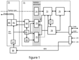
- FIG. 1 A non-limiting example of the implementation of the electronic circuit is shown in Figure 1 .
- This stage (71) also includes drivers (“Gate drivers” in English) (80) receiving the signals coming from the second galvanic isolator (79) and controlling the triggers of the MOSFET transistors constituting the inverter (81) of the power stage (72).
- the electronic control stage (71) also comprises a voltage step-down regulation and filtering circuit (82) for the 48 V power voltage to provide a 5 V voltage in the example described. It also comprises an analog-digital converter (83) providing the computer (73) via the galvanic isolator (75) with digital information which is the image of the 48 V power supply voltage applied to the inverter (81).
- the power voltage is transmitted to the inverter (81) via a filter (22') comprising the aforementioned capacitors (22) as well as inductors and standard filtering elements intended to eliminate the transient voltages.
- a current sensor (84) provides information corresponding to the 48 V direct current supply power of the inverter (81).
- the ceramic card (20) supports the power stage (72) formed by the inverter (81) as well as by components (85) providing capacitive decoupling at the terminals of each cell of the inverter (81), for example ceramic capacitors.
- An inverter cell (81) is formed in a known manner, according to an exemplary embodiment, by two MOSFET transistors.
- the difference between the set speed (90) and the rotor speed (86) enters the speed regulator (103).
- the computer (73) controls a second processing to determine the period of the pulse width modulation control signal (92) driving the inverter (81) in order to effectively reduce the number of switchings of the MOSFETs making up the active cell during the duration of each stator phasor, while guaranteeing acceptable phase current ripple, a low harmonic distortion rate and a tolerable peak phase current for the turbomachine in all its operating conditions.
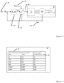
- the preferred embodiment of this processing is an algorithm using a table (91) recorded in the memory (77), making it possible to eliminate any calculation time, and to apply the appropriate period of the control signal (92) during each phasor change as a function of the instantaneous electrical frequency proportional to the speed of the rotor (86).
- the period of the control signal identified in the table (91) for each electrical frequency range is the result of a preliminary identification phase carried out by calculations, simulations and tests making it possible to guarantee the conditions on the phase currents mentioned above.
- the computer (72) controls a third processing to control the turbomachine and control the variable duty cycle of the pulse width modulated control signal of the inverter (81) in order to guarantee an optimal response when changing the speed setpoint, in particular in the form of steps.
- the main qualities of a speed-controlled turbomachine are: speed, stability and precision.
- the computer (73) controls a fourth processing to control the thermo-regulated machine in block commutation with a phase shift between the stator field and the rotor field as a function of the rotation speed of the rotor and the identification parameters of said thermo-regulated machine, said phase shift increasing as a function of said rotation speed.
- This is in fact to maximize the torque available during the first acceleration phase of the machine, therefore during a so-called constant torque phase.
- K E is a motor constant
- Î s ( t ) is the peak current value
- p the number of pole pairs of the machine
- ⁇ s ( t ) the position of the rotating magnetic field
- ⁇ ( t ) the position of the stator field.
- the fourth processing managed by the computer therefore aims to control the thermo-regulated machine in block commutation with a phase shift between the stator field and the rotor field constant value + ⁇ 2 adapting according to the rotation speed of the rotor and the identification parameters of said thermoregulated machine, said phase shift increasing according to said rotation speed.
- a phase shift is fixed materially during construction by the mechanical placement of the magnetosensitive elements relative to the placements of the stator coils of the machine. This processing will be supported by software functions stored in (77).
- the computer (73) controls a fifth processing to correct the time lag existing between the commutations provided by said probes assembled on the printed circuit (13), and the ideal commutation moments, synchronous with the real position of the rotor.
- This time lag has critical consequences on the turbomachine in view of the very high rotation speeds of the latter, significantly degrading its maximum power and its efficiency.
- Several distinct causes condition this lag such as the mechanical tolerances of the aluminum body (4), of the rotor and the stator of the motor and of the printed circuit (13), the alignment defects of the axes of the stator and the rotor and the positioning precision of the probes on said printed circuit (13).
- each probe i.e. the offset of the high commutations (from logic “0” to logic “1") in the case of a magnet transition at the North pole / South pole rotor and the offset of the low commutations (from logic "1" to logic “0") in the case of a magnet transition at the South pole / North pole rotor.
- the innovative and new method for correcting this offset consists of first carrying out an identification (96) of each offset during the final test of each turbomachine on its production line, then to apply with very few associated software resources the corrections memorized at each switching of probes (100).
- the method for identifying the different offsets consists of first applying a very precise rotation speed (97) (mechanical drive by an external means or control of the inverter in step-by-step mode), then measuring the offset between the zero crossings of the induced voltages, these being the image of the ideal commutations of the probes, and the effective commutations of the latter, to finally calculate the offset - advance or delay - of each of these commutations (98).
- the last step (99) consists of calculating and storing in the memory (77) the corrections to be applied when using the turbomachine with the corresponding application software. Each of these corrections must make it possible to correct an offset which may take the form of an advance or delay commutation.
- Correcting an early commutation consists of taking the latter into account after a latency time of the value of the advance measured during the identification phase (96). Correcting a late commutation is more complex, the method consists of using the two previous commutations and the error calculated by the servocontrol in order to determine the current speed of the rotor and to know if the turbomachine is in steady state or in acceleration phase. In the case of a steady state, the software emulates the "late" commutation before the latter exists by calculating a known duration based solely on the actual duration of the previous commutation corrected beforehand.
- the software emulates the "late" commutation before the latter exists by calculating a known duration derived from the actual duration of the previous commutation corrected beforehand and the speed increment applied by the turbomachine servocontrol.
- the identification step (98) must be carried out six times, for the two commutations of each of the three probes.
Landscapes
- Engineering & Computer Science (AREA)
- Power Engineering (AREA)
- Structures Of Non-Positive Displacement Pumps (AREA)
- Connection Of Motors, Electrical Generators, Mechanical Devices, And The Like (AREA)
- Control Of Motors That Do Not Use Commutators (AREA)
Claims (5)
- Verfahren für die Verwendung einer elektrischen Maschine mit Permanentmagnet, umfassend mehrere Statorphasen, wobei die Maschine durch eine elektronische Schaltung gelenkt wird, umfassend einen Rechner (73), der durch eine Batterie versorgt wird, die eine Batteriespannung liefert, die einen Durchschnittswert einer Spannung regelt, die durch einen Wechselrichter (81) an die Phasen der elektrischen Maschine angelegt wird, wobei die Überwachung des Durchschnittswerts der an die Phasen der elektrischen Maschine angelegten Spannung die Begrenzung der Motorphasenströme ermöglicht, um den Wechselrichter bis zu dem Maximum seiner Stromkapazitäten zu nutzen und gleichzeitig die Einhaltung von kritischen Schwellenwerten von Komponenten zu gewährleisten, und die ferner eine Messung der gemessenen Drehzahl des Rotors der elektrischen Maschine umfasst, wobei der Durchschnittswert der Spannung in Abhängigkeit von der Differenz zwischen der Solldrehzahl und der gemessenen Drehzahl des Rotors (101) der Maschine sowie von der Übertragungsfunktion (87) der Maschine und des Spannungspegels der Stromversorgungsbatterie der Maschine bestimmt wird,
dadurch gekennzeichnet, dass der Rechner (73) ein impulsbreitenmoduliertes Signal steuert und die variable Periode des Signals in Abhängigkeit steuert von:a) einerseits von Informationen, die die momentane elektrische Frequenz der Maschine darstellen, undb) andererseits von Informationen, die den Welligkeitsfaktor der Phasenströme der Maschine darstellen. - Verfahren für die Verwendung einer elektrischen Maschine nach Anspruch 1, dadurch gekennzeichnet, dass der Rechner (73) ein impulsbreitenmoduliertes Signal steuert und das variable Tastverhältnis des Steuersignals mittels einer proportional-integralen Drehzahlsteuerung mit festen Verstärkungen steuert, wobei der Integralterm aktiviert wird, wenn der Fehler zwischen der gewünschten Drehzahl des Rotors der Maschine und der gemessenen Drehzahl des Rotors kleiner als ein vorbestimmter Wert ist.
- Verfahren für die Verwendung einer elektrischen Maschine nach Anspruch 1, dadurch gekennzeichnet, dass die elektronische Schaltung die wärmegeregelte Maschine in Blockschaltung mit einer Sollphasenverschiebung zwischen dem Statorfeld und dem Rotorfeld der Maschine in Abhängigkeit von der Drehzahl des Rotors und den Identifikationsparametern der wärmegeregelten Maschine steuert, wobei die Sollphasenverschiebung in Abhängigkeit von der Drehzahl zunimmt.
- Verfahren für die Verwendung einer elektrischen Maschine nach Anspruch 1, dadurch gekennzeichnet, dass die Position des Rotors der Maschine mittels magnetosensitiver Sonden bestimmt wird, die auf einer gedruckten Schaltung (13) in dem Hauptmodul (1) und in der Nähe des Rotors montiert sind, wobei die Sonden die Position des Rotors erfassen, und dass der Rechner (73) einen Code ausführt, der den Versatz zwischen den durch die Sonden bereitgestellten Kommutierungen und der tatsächlichen Position des Rotors in Abhängigkeit einer in einem Speicher des Rechners aufgezeichneten Korrekturtabelle korrigiert, mindestens während eines Schritts zum Identifizieren der elektrischen Maschine e.
- Verfahren für die Verwendung einer elektrischen Maschine nach einem der vorstehenden Ansprüche, dadurch gekennzeichnet, dass die Maschine eine Turbomaschine ist.
Applications Claiming Priority (2)
| Application Number | Priority Date | Filing Date | Title |
|---|---|---|---|
| FR1752830A FR3064840B1 (fr) | 2017-04-03 | 2017-04-03 | Machine electrique haute puissance thermoregulee |
| PCT/EP2018/058410 WO2018185061A1 (fr) | 2017-04-03 | 2018-04-03 | Machine electrique haute puissance thermoregulee |
Publications (2)
| Publication Number | Publication Date |
|---|---|
| EP3607649A1 EP3607649A1 (de) | 2020-02-12 |
| EP3607649B1 true EP3607649B1 (de) | 2025-07-02 |
Family
ID=59253679
Family Applications (1)
| Application Number | Title | Priority Date | Filing Date |
|---|---|---|---|
| EP18713703.9A Active EP3607649B1 (de) | 2017-04-03 | 2018-04-03 | Temperaturgesteuerte elektrische hochleistungsmaschine |
Country Status (3)
| Country | Link |
|---|---|
| EP (1) | EP3607649B1 (de) |
| FR (1) | FR3064840B1 (de) |
| WO (1) | WO2018185061A1 (de) |
Families Citing this family (5)
| Publication number | Priority date | Publication date | Assignee | Title |
|---|---|---|---|---|
| US10862371B2 (en) * | 2018-12-14 | 2020-12-08 | Bendix Commercial Vehicle Systems Llc | Perimeter liquid-cooled electric machine and integrated power inverter |
| CN114123569A (zh) * | 2021-12-01 | 2022-03-01 | 湖南龙德晟机电科技有限公司 | 一种高效节能的小型电机及接线方法 |
| EP4329166A1 (de) * | 2022-08-26 | 2024-02-28 | Valeo eAutomotive Germany GmbH | Anordnung, die einen elektromotor und einen umrichter umfasst, und verfahren zum zusammenbau der anordnung |
| CN117955297B (zh) * | 2024-03-26 | 2024-07-19 | 常州拓昂电机有限公司 | 一种具有自动除尘功能的空调风机用无刷电机 |
| CN119093643B (zh) * | 2024-08-26 | 2025-03-11 | 常州巨浪机械有限公司 | 一种高效散热防尘电机端盖结构及散热防尘方法 |
Family Cites Families (13)
| Publication number | Priority date | Publication date | Assignee | Title |
|---|---|---|---|---|
| US5818192A (en) * | 1995-08-04 | 1998-10-06 | The Boeing Company | Starting of synchronous machine without rotor position of speed measurement |
| JPH11257352A (ja) * | 1998-03-13 | 1999-09-21 | Hitachi Ltd | 磁気軸受及びそれを搭載した回転機械並びに回転機械の運転方法 |
| DE10063321A1 (de) * | 2000-12-19 | 2002-06-20 | Gfas Mbh Ges Fuer Aufladetechn | Elektrisch angetriebener Strömungsverdichter |
| US7053583B1 (en) * | 2005-04-06 | 2006-05-30 | Delphi Technologies, Inc. | Brushless DC motor control |
| JP2008193790A (ja) * | 2007-02-02 | 2008-08-21 | Ihi Corp | 電動機付ターボチャージャ用電動機駆動装置 |
| JP4811290B2 (ja) * | 2007-02-13 | 2011-11-09 | 株式会社Ihi | モータ制御駆動装置 |
| DE102009044921A1 (de) | 2009-09-23 | 2011-04-07 | Robert Bosch Gmbh | Elektrischer Turbolader |
| JP5492599B2 (ja) * | 2010-02-26 | 2014-05-14 | 日立オートモティブシステムズ株式会社 | 回転電機システム |
| CN103814515B (zh) * | 2011-09-20 | 2016-05-04 | 三菱电机株式会社 | 机电一体型组件 |
| FR2991009B1 (fr) | 2012-05-22 | 2014-05-16 | Valeo Sys Controle Moteur Sas | Boitier de compresseur electrique comprenant un dispositif de dissipation, et compresseur comportant un tel boitier |
| DE102012010348A1 (de) * | 2012-05-25 | 2013-11-28 | GM Global Technology Operations LLC (n. d. Ges. d. Staates Delaware) | Verfahren und Vorrichtung zur Steuerung eineselektrischen Stellantriebes für eineWastegate-Ventilanordnung eines Abgasturboladers |
| GB2509799B (en) * | 2013-06-26 | 2015-10-07 | Protean Electric Ltd | An electric motor or generator |
| WO2015036921A2 (en) * | 2013-09-10 | 2015-03-19 | Protean Electric Limited | Electric motor or generator |
-
2017
- 2017-04-03 FR FR1752830A patent/FR3064840B1/fr not_active Expired - Fee Related
-
2018
- 2018-04-03 EP EP18713703.9A patent/EP3607649B1/de active Active
- 2018-04-03 WO PCT/EP2018/058410 patent/WO2018185061A1/fr not_active Ceased
Also Published As
| Publication number | Publication date |
|---|---|
| FR3064840A1 (fr) | 2018-10-05 |
| EP3607649A1 (de) | 2020-02-12 |
| FR3064840B1 (fr) | 2019-12-27 |
| WO2018185061A1 (fr) | 2018-10-11 |
Similar Documents
| Publication | Publication Date | Title |
|---|---|---|
| EP2684289B1 (de) | In einem stromwandler implementiertes steuerverfahren zur identifizierung von parametern in bezug auf die magnetische sättigung eines elektromotors | |
| EP2997654A1 (de) | Verfahren zur schätzung der winkelposition des rotors einer mehrphasigen elektrischen drehmaschine und anwendung zur steuerung eines mehrphasigen wechselrichters für solch eine maschine | |
| FR2985113A1 (fr) | Onduleur de pilotage avec detecteur d'ondulation anormale de couple | |
| EP3607649A1 (de) | Temperaturgesteuerte elektrische hochleistungsmaschine | |
| WO2020020924A1 (fr) | Procede de verification du calage d'un capteur de position angulaire d'un rotor pour vehicule | |
| FR2985112A1 (fr) | Onduleur de pilotage avec detecteur d'erreur de couple | |
| EP3069441A1 (de) | Verfahren und system zur steuerung eines mit geschnittenen spannungen versorgten kraftfahrzeug-drehstrom-elektromotors | |
| EP4216424B1 (de) | Verfahren und system zur steuerung einer von einem wechselrichter gesteuerten elektrischen maschine mit mehreren schaltarmen mit zwei servoverfahren | |
| EP2870018B1 (de) | Verfahren zur steuerung eines antriebsstranges und entsprechendes system | |
| FR3044185A1 (fr) | Procede de commande d'une machine synchrone a aimants permanents, et dispositif correspondant | |
| FR3112043A1 (fr) | Procédé et système de commande d’une machine électrique synchrone | |
| EP3560095B1 (de) | Verfahren zum bestimmen einer direktachseninduktivität und einer quadraturachseninduktivität einer elektrischen maschine, entsprechendes computerprogramm und vorrichtung | |
| FR3022709A1 (fr) | Procede de controle de la position d'un rotor de machine electrique | |
| EP4466785B1 (de) | Vorrichtung und verfahren zur steuerung einer synchronmaschine und zur rotorpositionsschätzung von inbetriebnahme auf eine vorbestimmte niedrige geschwindigkeit | |
| WO2023073317A1 (fr) | Procédé de calage automatique d'un capteur de position angulaire | |
| EP3503380A1 (de) | Steuerverfahren eines elektromotors, das eine identifizierungssequenz eines transformators umfasst | |
| FR3156263A1 (fr) | Procédé de commande d’une machine électrique au moyen d’un contrôleur avec un régulateur proportionnel et un régulateur proportionnel intégral | |
| WO2023117402A1 (fr) | Procede et systeme de commande d'une machine electrique pilotee par un onduleur pourvu de plusieurs bras de commutation | |
| EP3529889B1 (de) | Verfahren und vorrichtungen zur schätzung einer winkelposition eines rotors | |
| EP4387084A1 (de) | Verfahren zur steuerung einer von einem wechselrichter gesteuerten elektrischen maschine mit einer vielzahl von schaltarmen | |
| WO2023222980A1 (fr) | Dispositif de contrôle pour une machine tournante triphasée synchrone à aimants permanents | |
| FR3024616A1 (fr) | Procede et dispositif de commande du couple electromagnetique d'un groupe motopropulseur | |
| EP2992602A1 (de) | Verfahren zur überprüfung der funktionsfähigkeit einer antriebseinheit für ein kraftfahrzeug und entsprechendes system | |
| FR3073691A1 (fr) | Procede de commande d'une machine electrique synchrone | |
| WO2015121049A2 (fr) | Procede de commande d'une machine electrique a aimant permanent optimisant les pertes joule |
Legal Events
| Date | Code | Title | Description |
|---|---|---|---|
| STAA | Information on the status of an ep patent application or granted ep patent |
Free format text: STATUS: UNKNOWN |
|
| STAA | Information on the status of an ep patent application or granted ep patent |
Free format text: STATUS: THE INTERNATIONAL PUBLICATION HAS BEEN MADE |
|
| PUAI | Public reference made under article 153(3) epc to a published international application that has entered the european phase |
Free format text: ORIGINAL CODE: 0009012 |
|
| STAA | Information on the status of an ep patent application or granted ep patent |
Free format text: STATUS: REQUEST FOR EXAMINATION WAS MADE |
|
| 17P | Request for examination filed |
Effective date: 20190927 |
|
| AK | Designated contracting states |
Kind code of ref document: A1 Designated state(s): AL AT BE BG CH CY CZ DE DK EE ES FI FR GB GR HR HU IE IS IT LI LT LU LV MC MK MT NL NO PL PT RO RS SE SI SK SM TR |
|
| AX | Request for extension of the european patent |
Extension state: BA ME |
|
| DAV | Request for validation of the european patent (deleted) | ||
| DAX | Request for extension of the european patent (deleted) | ||
| STAA | Information on the status of an ep patent application or granted ep patent |
Free format text: STATUS: EXAMINATION IS IN PROGRESS |
|
| 17Q | First examination report despatched |
Effective date: 20210527 |
|
| GRAP | Despatch of communication of intention to grant a patent |
Free format text: ORIGINAL CODE: EPIDOSNIGR1 |
|
| STAA | Information on the status of an ep patent application or granted ep patent |
Free format text: STATUS: GRANT OF PATENT IS INTENDED |
|
| INTG | Intention to grant announced |
Effective date: 20250131 |
|
| GRAS | Grant fee paid |
Free format text: ORIGINAL CODE: EPIDOSNIGR3 |
|
| GRAA | (expected) grant |
Free format text: ORIGINAL CODE: 0009210 |
|
| STAA | Information on the status of an ep patent application or granted ep patent |
Free format text: STATUS: THE PATENT HAS BEEN GRANTED |
|
| AK | Designated contracting states |
Kind code of ref document: B1 Designated state(s): AL AT BE BG CH CY CZ DE DK EE ES FI FR GB GR HR HU IE IS IT LI LT LU LV MC MK MT NL NO PL PT RO RS SE SI SK SM TR |
|
| REG | Reference to a national code |
Ref country code: GB Ref legal event code: FG4D Free format text: NOT ENGLISH |
|
| REG | Reference to a national code |
Ref country code: CH Ref legal event code: EP |
|
| REG | Reference to a national code |
Ref country code: IE Ref legal event code: FG4D Free format text: LANGUAGE OF EP DOCUMENT: FRENCH |
|
| REG | Reference to a national code |
Ref country code: DE Ref legal event code: R096 Ref document number: 602018083160 Country of ref document: DE |
|
| REG | Reference to a national code |
Ref country code: NL Ref legal event code: MP Effective date: 20250702 |
|
| PG25 | Lapsed in a contracting state [announced via postgrant information from national office to epo] |
Ref country code: PT Free format text: LAPSE BECAUSE OF FAILURE TO SUBMIT A TRANSLATION OF THE DESCRIPTION OR TO PAY THE FEE WITHIN THE PRESCRIBED TIME-LIMIT Effective date: 20251103 |
|
| PG25 | Lapsed in a contracting state [announced via postgrant information from national office to epo] |
Ref country code: NL Free format text: LAPSE BECAUSE OF FAILURE TO SUBMIT A TRANSLATION OF THE DESCRIPTION OR TO PAY THE FEE WITHIN THE PRESCRIBED TIME-LIMIT Effective date: 20250702 |
|
| REG | Reference to a national code |
Ref country code: AT Ref legal event code: MK05 Ref document number: 1810432 Country of ref document: AT Kind code of ref document: T Effective date: 20250702 |
|
| PG25 | Lapsed in a contracting state [announced via postgrant information from national office to epo] |
Ref country code: IS Free format text: LAPSE BECAUSE OF FAILURE TO SUBMIT A TRANSLATION OF THE DESCRIPTION OR TO PAY THE FEE WITHIN THE PRESCRIBED TIME-LIMIT Effective date: 20251102 |
|
| PG25 | Lapsed in a contracting state [announced via postgrant information from national office to epo] |
Ref country code: NO Free format text: LAPSE BECAUSE OF FAILURE TO SUBMIT A TRANSLATION OF THE DESCRIPTION OR TO PAY THE FEE WITHIN THE PRESCRIBED TIME-LIMIT Effective date: 20251002 |
|
| REG | Reference to a national code |
Ref country code: LT Ref legal event code: MG9D |
|
| PG25 | Lapsed in a contracting state [announced via postgrant information from national office to epo] |
Ref country code: AT Free format text: LAPSE BECAUSE OF FAILURE TO SUBMIT A TRANSLATION OF THE DESCRIPTION OR TO PAY THE FEE WITHIN THE PRESCRIBED TIME-LIMIT Effective date: 20250702 |
|
| PG25 | Lapsed in a contracting state [announced via postgrant information from national office to epo] |
Ref country code: FI Free format text: LAPSE BECAUSE OF FAILURE TO SUBMIT A TRANSLATION OF THE DESCRIPTION OR TO PAY THE FEE WITHIN THE PRESCRIBED TIME-LIMIT Effective date: 20250702 |
|
| PG25 | Lapsed in a contracting state [announced via postgrant information from national office to epo] |
Ref country code: HR Free format text: LAPSE BECAUSE OF FAILURE TO SUBMIT A TRANSLATION OF THE DESCRIPTION OR TO PAY THE FEE WITHIN THE PRESCRIBED TIME-LIMIT Effective date: 20250702 |
|
| PG25 | Lapsed in a contracting state [announced via postgrant information from national office to epo] |
Ref country code: GR Free format text: LAPSE BECAUSE OF FAILURE TO SUBMIT A TRANSLATION OF THE DESCRIPTION OR TO PAY THE FEE WITHIN THE PRESCRIBED TIME-LIMIT Effective date: 20251003 |
|
| PG25 | Lapsed in a contracting state [announced via postgrant information from national office to epo] |
Ref country code: SE Free format text: LAPSE BECAUSE OF FAILURE TO SUBMIT A TRANSLATION OF THE DESCRIPTION OR TO PAY THE FEE WITHIN THE PRESCRIBED TIME-LIMIT Effective date: 20250702 Ref country code: CZ Free format text: LAPSE BECAUSE OF FAILURE TO SUBMIT A TRANSLATION OF THE DESCRIPTION OR TO PAY THE FEE WITHIN THE PRESCRIBED TIME-LIMIT Effective date: 20250702 |
|
| PG25 | Lapsed in a contracting state [announced via postgrant information from national office to epo] |
Ref country code: LV Free format text: LAPSE BECAUSE OF FAILURE TO SUBMIT A TRANSLATION OF THE DESCRIPTION OR TO PAY THE FEE WITHIN THE PRESCRIBED TIME-LIMIT Effective date: 20250702 |
|
| PG25 | Lapsed in a contracting state [announced via postgrant information from national office to epo] |
Ref country code: BG Free format text: LAPSE BECAUSE OF FAILURE TO SUBMIT A TRANSLATION OF THE DESCRIPTION OR TO PAY THE FEE WITHIN THE PRESCRIBED TIME-LIMIT Effective date: 20250702 Ref country code: PL Free format text: LAPSE BECAUSE OF FAILURE TO SUBMIT A TRANSLATION OF THE DESCRIPTION OR TO PAY THE FEE WITHIN THE PRESCRIBED TIME-LIMIT Effective date: 20250702 |
|
| PG25 | Lapsed in a contracting state [announced via postgrant information from national office to epo] |
Ref country code: RS Free format text: LAPSE BECAUSE OF FAILURE TO SUBMIT A TRANSLATION OF THE DESCRIPTION OR TO PAY THE FEE WITHIN THE PRESCRIBED TIME-LIMIT Effective date: 20251002 |
|
| PG25 | Lapsed in a contracting state [announced via postgrant information from national office to epo] |
Ref country code: ES Free format text: LAPSE BECAUSE OF FAILURE TO SUBMIT A TRANSLATION OF THE DESCRIPTION OR TO PAY THE FEE WITHIN THE PRESCRIBED TIME-LIMIT Effective date: 20250702 |
|
| PG25 | Lapsed in a contracting state [announced via postgrant information from national office to epo] |
Ref country code: SM Free format text: LAPSE BECAUSE OF FAILURE TO SUBMIT A TRANSLATION OF THE DESCRIPTION OR TO PAY THE FEE WITHIN THE PRESCRIBED TIME-LIMIT Effective date: 20250702 |
|
| PG25 | Lapsed in a contracting state [announced via postgrant information from national office to epo] |
Ref country code: DK Free format text: LAPSE BECAUSE OF FAILURE TO SUBMIT A TRANSLATION OF THE DESCRIPTION OR TO PAY THE FEE WITHIN THE PRESCRIBED TIME-LIMIT Effective date: 20250702 |
|
| PG25 | Lapsed in a contracting state [announced via postgrant information from national office to epo] |
Ref country code: IT Free format text: LAPSE BECAUSE OF FAILURE TO SUBMIT A TRANSLATION OF THE DESCRIPTION OR TO PAY THE FEE WITHIN THE PRESCRIBED TIME-LIMIT Effective date: 20250702 |
|
| PG25 | Lapsed in a contracting state [announced via postgrant information from national office to epo] |
Ref country code: SK Free format text: LAPSE BECAUSE OF FAILURE TO SUBMIT A TRANSLATION OF THE DESCRIPTION OR TO PAY THE FEE WITHIN THE PRESCRIBED TIME-LIMIT Effective date: 20250702 Ref country code: EE Free format text: LAPSE BECAUSE OF FAILURE TO SUBMIT A TRANSLATION OF THE DESCRIPTION OR TO PAY THE FEE WITHIN THE PRESCRIBED TIME-LIMIT Effective date: 20250702 |
|
| PLBE | No opposition filed within time limit |
Free format text: ORIGINAL CODE: 0009261 |
|
| STAA | Information on the status of an ep patent application or granted ep patent |
Free format text: STATUS: NO OPPOSITION FILED WITHIN TIME LIMIT |