EP3607617B1 - Cable connector - Google Patents
Cable connector Download PDFInfo
- Publication number
- EP3607617B1 EP3607617B1 EP17916455.3A EP17916455A EP3607617B1 EP 3607617 B1 EP3607617 B1 EP 3607617B1 EP 17916455 A EP17916455 A EP 17916455A EP 3607617 B1 EP3607617 B1 EP 3607617B1
- Authority
- EP
- European Patent Office
- Prior art keywords
- tab
- resilient hook
- cable connector
- socket
- cavity
- Prior art date
- Legal status (The legal status is an assumption and is not a legal conclusion. Google has not performed a legal analysis and makes no representation as to the accuracy of the status listed.)
- Active
Links
- 230000006835 compression Effects 0.000 claims description 19
- 238000007906 compression Methods 0.000 claims description 19
- 230000007246 mechanism Effects 0.000 claims description 14
- 239000012858 resilient material Substances 0.000 claims 1
- 239000000463 material Substances 0.000 description 5
- 230000008901 benefit Effects 0.000 description 4
- 238000000034 method Methods 0.000 description 4
- 230000005611 electricity Effects 0.000 description 3
- 238000010137 moulding (plastic) Methods 0.000 description 3
- 230000000694 effects Effects 0.000 description 2
- 238000010891 electric arc Methods 0.000 description 2
- 208000012661 Dyskinesia Diseases 0.000 description 1
- 208000015592 Involuntary movements Diseases 0.000 description 1
- 230000015556 catabolic process Effects 0.000 description 1
- 230000008878 coupling Effects 0.000 description 1
- 238000010168 coupling process Methods 0.000 description 1
- 238000005859 coupling reaction Methods 0.000 description 1
- 230000009849 deactivation Effects 0.000 description 1
- 230000007613 environmental effect Effects 0.000 description 1
- 238000000605 extraction Methods 0.000 description 1
- 229920002457 flexible plastic Polymers 0.000 description 1
- 230000017311 musculoskeletal movement, spinal reflex action Effects 0.000 description 1
- 229920003023 plastic Polymers 0.000 description 1
- 230000008569 process Effects 0.000 description 1
Images

Classifications
-
- H—ELECTRICITY
- H01—ELECTRIC ELEMENTS
- H01R—ELECTRICALLY-CONDUCTIVE CONNECTIONS; STRUCTURAL ASSOCIATIONS OF A PLURALITY OF MUTUALLY-INSULATED ELECTRICAL CONNECTING ELEMENTS; COUPLING DEVICES; CURRENT COLLECTORS
- H01R13/00—Details of coupling devices of the kinds covered by groups H01R12/70 or H01R24/00 - H01R33/00
- H01R13/62—Means for facilitating engagement or disengagement of coupling parts or for holding them in engagement
- H01R13/627—Snap or like fastening
- H01R13/6271—Latching means integral with the housing
-
- H—ELECTRICITY
- H01—ELECTRIC ELEMENTS
- H01R—ELECTRICALLY-CONDUCTIVE CONNECTIONS; STRUCTURAL ASSOCIATIONS OF A PLURALITY OF MUTUALLY-INSULATED ELECTRICAL CONNECTING ELEMENTS; COUPLING DEVICES; CURRENT COLLECTORS
- H01R13/00—Details of coupling devices of the kinds covered by groups H01R12/70 or H01R24/00 - H01R33/00
- H01R13/62—Means for facilitating engagement or disengagement of coupling parts or for holding them in engagement
- H01R13/627—Snap or like fastening
- H01R13/6275—Latching arms not integral with the housing
-
- H—ELECTRICITY
- H01—ELECTRIC ELEMENTS
- H01R—ELECTRICALLY-CONDUCTIVE CONNECTIONS; STRUCTURAL ASSOCIATIONS OF A PLURALITY OF MUTUALLY-INSULATED ELECTRICAL CONNECTING ELEMENTS; COUPLING DEVICES; CURRENT COLLECTORS
- H01R24/00—Two-part coupling devices, or either of their cooperating parts, characterised by their overall structure
- H01R24/20—Coupling parts carrying sockets, clips or analogous contacts and secured only to wire or cable
- H01R24/22—Coupling parts carrying sockets, clips or analogous contacts and secured only to wire or cable with additional earth or shield contacts
-
- H—ELECTRICITY
- H01—ELECTRIC ELEMENTS
- H01R—ELECTRICALLY-CONDUCTIVE CONNECTIONS; STRUCTURAL ASSOCIATIONS OF A PLURALITY OF MUTUALLY-INSULATED ELECTRICAL CONNECTING ELEMENTS; COUPLING DEVICES; CURRENT COLLECTORS
- H01R24/00—Two-part coupling devices, or either of their cooperating parts, characterised by their overall structure
- H01R24/28—Coupling parts carrying pins, blades or analogous contacts and secured only to wire or cable
- H01R24/30—Coupling parts carrying pins, blades or analogous contacts and secured only to wire or cable with additional earth or shield contacts
-
- H—ELECTRICITY
- H01—ELECTRIC ELEMENTS
- H01R—ELECTRICALLY-CONDUCTIVE CONNECTIONS; STRUCTURAL ASSOCIATIONS OF A PLURALITY OF MUTUALLY-INSULATED ELECTRICAL CONNECTING ELEMENTS; COUPLING DEVICES; CURRENT COLLECTORS
- H01R13/00—Details of coupling devices of the kinds covered by groups H01R12/70 or H01R24/00 - H01R33/00
- H01R13/62—Means for facilitating engagement or disengagement of coupling parts or for holding them in engagement
- H01R13/639—Additional means for holding or locking coupling parts together, after engagement, e.g. separate keylock, retainer strap
-
- H—ELECTRICITY
- H01—ELECTRIC ELEMENTS
- H01R—ELECTRICALLY-CONDUCTIVE CONNECTIONS; STRUCTURAL ASSOCIATIONS OF A PLURALITY OF MUTUALLY-INSULATED ELECTRICAL CONNECTING ELEMENTS; COUPLING DEVICES; CURRENT COLLECTORS
- H01R2103/00—Two poles
-
- H—ELECTRICITY
- H01—ELECTRIC ELEMENTS
- H01R—ELECTRICALLY-CONDUCTIVE CONNECTIONS; STRUCTURAL ASSOCIATIONS OF A PLURALITY OF MUTUALLY-INSULATED ELECTRICAL CONNECTING ELEMENTS; COUPLING DEVICES; CURRENT COLLECTORS
- H01R2105/00—Three poles
Definitions
- the invention relates to a cable connector.
- the invention particularly relates to an electrical cable connector with lock which prevents involuntary electric supply interruption and can easily be mounted or detached manually even without viewing.
- Supply cables may have fixed connection to electrical devices like in most appliances or be removable like in computers.
- Removable supply cables may have a lock to secure the connection or be lockless.
- Electrical connection in lockless connectors is usually carried out by connecting female terminals on the supply cable to male terminals on the electrical device. Such connections do not have any lock mechanisms. Male and female terminals may become disconnected when electrical device is moved or any involuntary external force such as hit or bump exerted on the connection. Such disconnection may result in complete electric supply interruption or if the connection becomes loose, an electric arc may be generated. Such involuntary disconnections may result in electrical device breakdown. Another impact of power supply interruption to electrical devices such as a fridge which is supposed to run permanently is that the electrical device going out of service without the user noticing it.
- Supply connectors with lock have lock mechanisms which prevent involuntary disconnection of female and male terminals. Involuntary disconnection of electrical connectors does not happen unless intervened by the user. This ensures electrical devices stay securely connected to the mains supply.
- connection of connectors can be made easily, dismantling of the connector from the device has to be made visually and/or by use of tools. Since mains connection to the appliance is usually at hard-to-access areas on the device, detachment of the connector may take time. In some applications, connection is even harderto detach and therefore connector may have to be damaged to detach it.
- the patent numbered WO2008102544A1 is related to a lock structure for an electrical connection developed to have improved durability for repeated use and increased locking strength.
- This structure comprises first socket and a second socket connected to each other when either of them is pressed to the other.
- First connection body has an elastic engagement member
- the second connection body has a fixed engagement member. Engagement of elastic and fixed engagement members together prevents the disruption of the connection due to external forces accidentally.
- This kind of lock structure is well known from the prior art.
- the electrical signals of the electrical devices such as household appliances are transmitted through power supply cables.
- Such cable connection devices that transmit electrical signals comprise connectors or similar elements.
- the connection of the sockets may become loose or completely disrupted resulting in contact failure between electrical terminals. Therefore, in order to prevent involuntary electric supply interruption, a locking mechanism for connectors is developed.
- this type of a locking mechanism is described.
- the flexing engagement member is integral part of the socket, therefore the socket and the flexing engagement member has to be of the same material.
- the material specifications of the socket materials may not be sufficient for the repeated elastic movement of the flexing locking elements under stringent mechanical and thermal conditions. Those conditions cause changes in plastic material performance that result in mechanical failure in time. Therefore, this type of design with integrated engagement members may not be suitable for all environmental conditions.
- the need for an electric cable connector which prevents involuntary electric supply interruption that allows easy mounting and detachment even without viewing and insufficiency of current solutions have necessitated a development in the related art.
- the present invention relates to a cable connector according to claim 1 meeting the needs mentioned above eliminating probable drawbacks and providing some additional advantages over other current solutions.
- Main purpose of the cable connector disclosed under this invention is to provide easy mounting and detachment of the connection manually even with no visibility of connectors, meanwhile preventing involuntary electric supply interruption. Mounting and detachment of power supply cable can be made without using any tools, even not seeing the connection area and completely manually that exhibits an important advantage of use. This feature becomes important in places where electric outlet is difficult to access for instance, user wishes to mount or detach a power connection easily where the power connection to the electrical device and the mains supply are accessible only by hand and not possible to see. Moreover, a lock mechanism located on the connector is designed to carry pull forces required for the safety of the connection which eliminates electrical device failures or risk of melted cable and fire due to electric arc.
- the locking element is designed in different color. This feature becomes important by increasing visibility to help the user, particularly in places where visibility is limited and/or the connection area is poorly lighted.
- the cable connector consists of a female and a male socket.
- the female socket has male terminals on it whereas the male socket has female terminals on and electrical connection is realized by coupling of the male and the female terminals.
- Mechanical connection of these two parts of the assembly are realized by means of a tab located on the female socket and a resilient hook located on the male socket.
- the resilient hook goes into a guide channel on the female socket by flexing down and up and sits into the tab located on the upper surface of the channel. No additional part is needed for fixing the resilient hook into the housing. Since it is restricted from all four directions as it sits in the housing, it is fixed securely in place and therefore, no extra fixing component is needed.
- the top end of the resilient hook remains outside of the connection area after locking. When disconnection is required, this end extending beyond the locking area is manually pressed down and the lock is released.
- the developed cable connector consists of at least one female socket whereon male terminals are located, at least one male socket whereon female terminals are located, at least one resilient hook and at least one tab forming together at least one locking mechanism that enables interlocking of female and male sockets.
- the cable connector (10) which is the subject of the invention explained here, is designed in such a manner to prevent involuntary electric supply interruption and in the meantime allows easy manual mounting and detachment even without observing.
- the cable connector (10) in the broadest meaning, consists of at least one female socket (20) whereon male terminals (22) are located, at least one male socket (30) whereon female terminals (32) are located and at least one locking mechanism (16) having at least one tab (23) and at least one resilient hook (40) inserted in the tab (23) to provide interlocking of the female socket (20) and the male socket (30)
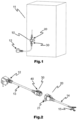
- Figures 1 and 2 show mounted view of the cable connector (10) on the electrical device (11) and perspective view of the cable connector (10) respectively.
- the female socket (20) is fixed on the electrical device (11) mechanically by means of the connection bracket (21) and electrically by means of the electrical terminals (15).
- the female terminals (32) located on the male socket (30) and the male terminals (22) located on the female socket (20) are interconnected and electric current supplied from the electrical plug (12) is transmitted to the electrical device (11) through the electric cable (13), the supply cable (14) and the electrical terminals (15).
- the female socket (20) is designed to be mounted on the electrical device (11) in fixed manner whereas the male socket (30) is designed to be removable.
- the male socket (30) supplies electricity from mains by means of the electrical plug (12) connected to it. Electrical connection is provided by interconnection of the male socket (30) and the female socket (20).
- FIG - 3 shows exploded view of the female socket (20) located on the cable connector (10) of the invention disclosed hereunder.
- the supply cable (14) connected to the female socket (20) has common electrical terminals (15) to provide connection to the electrical device (11).
- the said electrical terminals (15) can be in various sizes and forms in order to be compatible with the connections in the electrical device (11).
- the female socket (20) has a connection bracket (21) so as to fix it onto the electrical device (11).
- the tab (23) located on the female socket is structurally in triangle form.
- the tab front surface (23a) has a slope so as to fit into the tab cavity (42) in the locking mechanism (16).
- the tab rear surface (23b) is preferably designed in perpendicular form to prevent involuntary disconnection from the tab cavity (42) while in locked status.
- the guide channel (24) located on the female socket (20) is in the size and form to tightly surround the resilient hook (40) and the resilient hook housing (33).
- the female socket (20) is connected to the male terminals (22) mechanically and electrically.
- the female socket (20), together with all its components is integrated using plastic moulding method to insulate both electrically and against other external effects.
- FIG - 4 shows exploded view of the male socket (30) provided on the cable connector (10) in the invention disclosed hereunder.
- the locking mechanism (16) contains a resilient hook (40) located on the male socket (30) and a resilient hook housing (33).
- the resilient hook (40) consists of a tab cavity (42) where the tab (23) located on the female socket (20) can be inserted in, a cavity front surface (44) limiting backward movement of the tab cavity (42), a cavity rear surface (43) located on the opposite side and cavity side surfaces (49). Thanks to this structure, after the tab (23) is inserted in the resilient hook (40), disconnection of the male terminals (22) and the female terminals (32) due to involuntary movements is prevented.
- Deactivation of the locking mechanism (16), whenever desired, which disconnects the male socket (30) from the female socket (20) can be achieved by pressing the unlocking point (41) located on the resilient hook (40) that moves the resilent hook in plus direction (+) or minus direction (-).
- the tab (23) is released from the tab cavity (42) and this enables disconnection of the male socket (30) from the female socket (20).
- the resilient hook (40) moves in plus direction (+) and takes its initial position.
- the resilient hook (40) is produced separately and mounted into the resilient hook housing (33) after plastic moulding process.
- the rear compression surface (45), the side compression surface (46), the upper compression surface (47) and the front compression surface (48) on the resilient hook (40) enable fixing of the resilient hook (40) into the resilient hook housing (33).
- the rear compression surface (45) on the resilient hook (40) rests against the housing rear surface (33b); the side compression surface (46) against the housing side surface (33a); the upper compression surface (47) and the front compression surface (48) against the housing front surface (33c); therefore the resilient hook (40) in the resilient hook housing (33) is constricted in all four directions
- the resilient hook (40) and the tab (23) are designed in such manner to carry the pull forces required for safety between the male socket (30) and the female socket (20).
- the resilient hook (40) has preferably different colour than of the male socket (30) and the female socket (20). Particularly, in places where visibility is limited and/or the area the cable connector (10) located has little light, different colour of the resilient hook (40) increases noticeability and facilitates mounting and detaching of the cable connector (10).
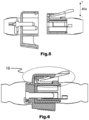
- Figure - 5 and Figure - 6 show cross section views of the cable connector (10) of the invention respectively in unconnected and connected situations. While the male terminals (32) and the female terminals (22) provide electrical connection, two components of the locking system (16), namely, the tab (23) and the resilient hook (40) provide mechanical connection.
- the resilient hook (40) is made of a flexible plastic material and designed in such a way to flex easily in plus (+) and minus (-) directions on the hook motion axis (40a).
- the tab front surface (23a) gets in touch with the resilient hook (40) and moves the resilient hook (40) in minus direction (-) with surface pressure and the tab (23) fully enters in the tab cavity (42) as a result of axial motion, and the resilient hook (40) moves back in plus direction (+) under spring effect and traps the tab (23) in the tab cavity (42).
- the resilient hook housing (33) and the resilient hook (40) fit completely into the guide channel (24).
- a push force is applied onto the unlocking point (41) in minus direction (-) in order to deactivate the locking mechanism (16).
- the male socket (30) may disconnect from the female socket (20) after the cavity front surface (44) moves in minus direction (-) on the hook motion axis (40a) and goes below the tab rear surface (23b) level.
- the male terminals (22) move out of the female terminal housing (31) and become disconnected with the female terminals (32) and both electrical and mechanical disconnections are achieved.
Landscapes
- Details Of Connecting Devices For Male And Female Coupling (AREA)
- Coupling Device And Connection With Printed Circuit (AREA)
Applications Claiming Priority (2)
| Application Number | Priority Date | Filing Date | Title |
|---|---|---|---|
| TR2017/05300A TR201705300A2 (tr) | 2017-04-10 | 2017-04-10 | |
| PCT/TR2017/050690 WO2019017859A2 (en) | 2017-04-10 | 2017-12-22 | CABLE CONNECTOR |
Publications (2)
| Publication Number | Publication Date |
|---|---|
| EP3607617A2 EP3607617A2 (en) | 2020-02-12 |
| EP3607617B1 true EP3607617B1 (en) | 2023-04-19 |
Family
ID=64870542
Family Applications (1)
| Application Number | Title | Priority Date | Filing Date |
|---|---|---|---|
| EP17916455.3A Active EP3607617B1 (en) | 2017-04-10 | 2017-12-22 | Cable connector |
Country Status (4)
| Country | Link |
|---|---|
| US (1) | US10826232B2 (tr) |
| EP (1) | EP3607617B1 (tr) |
| TR (1) | TR201705300A2 (tr) |
| WO (1) | WO2019017859A2 (tr) |
Families Citing this family (2)
| Publication number | Priority date | Publication date | Assignee | Title |
|---|---|---|---|---|
| ES1222987Y (es) * | 2018-10-15 | 2019-04-09 | Valco Melton S L U | Conector para suministrar potencia electrica |
| DE102019208994A1 (de) * | 2019-06-19 | 2020-12-24 | BSH Hausgeräte GmbH | Kaltgerätesteckerbuchse mit Verriegelungselement, Gehäusestecker und Kaltgerät |
Citations (2)
| Publication number | Priority date | Publication date | Assignee | Title |
|---|---|---|---|---|
| US3316523A (en) * | 1964-11-20 | 1967-04-25 | George J Trangmar | Electrical cord accessory |
| DE3440043A1 (de) * | 1984-11-02 | 1986-05-07 | F. Wieland, Elektrische Industrie GmbH, 8600 Bamberg | Elektrische steckverbindung |
Family Cites Families (10)
| Publication number | Priority date | Publication date | Assignee | Title |
|---|---|---|---|---|
| US3713076A (en) * | 1971-09-30 | 1973-01-23 | Electronic Eng Co | Locking electrical cable connection apparatus |
| JP4903599B2 (ja) | 2007-02-21 | 2012-03-28 | 株式会社ニフコ | 電気的接続器具のロック構造 |
| US8469734B2 (en) * | 2010-04-20 | 2013-06-25 | Liang Light Chen | Retainer system for electric cable couplers |
| JP5434786B2 (ja) | 2010-05-14 | 2014-03-05 | 住友電装株式会社 | コネクタ |
| DE102011007763A1 (de) | 2011-04-20 | 2012-10-25 | Bayerische Motoren Werke Aktiengesellschaft | Adapterkabel zur Wandlung eines an einem Fahrzeugladekabel vorgesehenen Anschlusses eines ersten Typs in einen Anschluss zweiten Typs |
| US9814157B2 (en) * | 2013-02-28 | 2017-11-07 | Tyco Fire & Security Gmbh | Wire management and wire entry cover bracket |
| EP3016213B1 (en) * | 2014-10-27 | 2018-02-14 | Delphi International Operations Luxembourg S.à r.l. | CPA device for direct mating and unmating |
| FR3051079B1 (fr) * | 2016-05-03 | 2018-06-15 | Eaxtron | Dispositif de verrouillage pour connecteurs electriques et connecteurs electriques equipes du dispositif. |
| US10320122B2 (en) * | 2017-02-25 | 2019-06-11 | Vaios Nikolaos Bozikis | Double side adjustable electrical cord securement device |
| US10404012B1 (en) * | 2018-04-20 | 2019-09-03 | Te Connectivity Corporation | Electrical connector with connector position assurance element |
-
2017
- 2017-04-10 TR TR2017/05300A patent/TR201705300A2/tr unknown
- 2017-12-20 US US16/494,442 patent/US10826232B2/en active Active
- 2017-12-22 WO PCT/TR2017/050690 patent/WO2019017859A2/en unknown
- 2017-12-22 EP EP17916455.3A patent/EP3607617B1/en active Active
Patent Citations (2)
| Publication number | Priority date | Publication date | Assignee | Title |
|---|---|---|---|---|
| US3316523A (en) * | 1964-11-20 | 1967-04-25 | George J Trangmar | Electrical cord accessory |
| DE3440043A1 (de) * | 1984-11-02 | 1986-05-07 | F. Wieland, Elektrische Industrie GmbH, 8600 Bamberg | Elektrische steckverbindung |
Also Published As
| Publication number | Publication date |
|---|---|
| EP3607617A2 (en) | 2020-02-12 |
| US10826232B2 (en) | 2020-11-03 |
| WO2019017859A2 (en) | 2019-01-24 |
| US20200091653A1 (en) | 2020-03-19 |
| WO2019017859A3 (en) | 2019-03-21 |
| TR201705300A2 (tr) | 2018-10-22 |
Similar Documents
| Publication | Publication Date | Title |
|---|---|---|
| US8602809B2 (en) | Locking cover for electrical connection appliance | |
| US7758370B1 (en) | Quick release electrical connector | |
| US20070161262A1 (en) | Detachable magnetic electrical connector | |
| JP2020077490A (ja) | 電気コネクタ、および電気コネクタセット | |
| CN110534969B (zh) | 电连接器及具有该电连接器的连接器组合 | |
| CA2691026C (en) | Single-pole electrical connector having a steel retaining spring | |
| EP3607617B1 (en) | Cable connector | |
| CN107453125B (zh) | 用于电连接器的锁定装置和配备该装置的电连接器 | |
| EP1935062A1 (en) | Hot plug wire contact and connector assembly | |
| US12057658B2 (en) | Electrical contact device with interlock | |
| US7195510B2 (en) | Electrical connector systems with latching assemblies and methods thereof | |
| US8573993B2 (en) | Connector | |
| US8591249B2 (en) | Flexible breakaway connector | |
| US6966790B2 (en) | Lockable electrical plug and socket connection | |
| US7867008B1 (en) | Water-proof connector assembly | |
| JP6334672B2 (ja) | ラッチコネクタアセンブリ | |
| CN102113181B (zh) | 连接器系统和短接构件 | |
| KR20140097295A (ko) | 플러그형 연결 | |
| EP2410619B1 (en) | Water-proof connector assembly | |
| WO1995031018A1 (en) | Electrical coupling | |
| CN217823534U (zh) | 一种连接器及用电设备 | |
| WO2010126666A1 (en) | Electrical connector | |
| US20170358875A1 (en) | Electrical contact with anti-rotation feature | |
| TWM565420U (zh) | Electrical connector | |
| CN219610879U (zh) | 一种电气连接器及电子产品 |
Legal Events
| Date | Code | Title | Description |
|---|---|---|---|
| STAA | Information on the status of an ep patent application or granted ep patent |
Free format text: STATUS: UNKNOWN |
|
| STAA | Information on the status of an ep patent application or granted ep patent |
Free format text: STATUS: THE INTERNATIONAL PUBLICATION HAS BEEN MADE |
|
| PUAI | Public reference made under article 153(3) epc to a published international application that has entered the european phase |
Free format text: ORIGINAL CODE: 0009012 |
|
| STAA | Information on the status of an ep patent application or granted ep patent |
Free format text: STATUS: REQUEST FOR EXAMINATION WAS MADE |
|
| 17P | Request for examination filed |
Effective date: 20191106 |
|
| AK | Designated contracting states |
Kind code of ref document: A2 Designated state(s): AL AT BE BG CH CY CZ DE DK EE ES FI FR GB GR HR HU IE IS IT LI LT LU LV MC MK MT NL NO PL PT RO RS SE SI SK SM TR |
|
| AX | Request for extension of the european patent |
Extension state: BA ME |
|
| DAV | Request for validation of the european patent (deleted) | ||
| DAX | Request for extension of the european patent (deleted) | ||
| STAA | Information on the status of an ep patent application or granted ep patent |
Free format text: STATUS: EXAMINATION IS IN PROGRESS |
|
| 17Q | First examination report despatched |
Effective date: 20200902 |
|
| STAA | Information on the status of an ep patent application or granted ep patent |
Free format text: STATUS: EXAMINATION IS IN PROGRESS |
|
| 17Q | First examination report despatched |
Effective date: 20210223 |
|
| STAA | Information on the status of an ep patent application or granted ep patent |
Free format text: STATUS: EXAMINATION IS IN PROGRESS |
|
| GRAP | Despatch of communication of intention to grant a patent |
Free format text: ORIGINAL CODE: EPIDOSNIGR1 |
|
| STAA | Information on the status of an ep patent application or granted ep patent |
Free format text: STATUS: GRANT OF PATENT IS INTENDED |
|
| INTG | Intention to grant announced |
Effective date: 20221221 |
|
| GRAS | Grant fee paid |
Free format text: ORIGINAL CODE: EPIDOSNIGR3 |
|
| GRAA | (expected) grant |
Free format text: ORIGINAL CODE: 0009210 |
|
| STAA | Information on the status of an ep patent application or granted ep patent |
Free format text: STATUS: THE PATENT HAS BEEN GRANTED |
|
| AK | Designated contracting states |
Kind code of ref document: B1 Designated state(s): AL AT BE BG CH CY CZ DE DK EE ES FI FR GB GR HR HU IE IS IT LI LT LU LV MC MK MT NL NO PL PT RO RS SE SI SK SM TR |
|
| REG | Reference to a national code |
Ref country code: GB Ref legal event code: FG4D |
|
| REG | Reference to a national code |
Ref country code: CH Ref legal event code: EP |
|
| REG | Reference to a national code |
Ref country code: DE Ref legal event code: R096 Ref document number: 602017067973 Country of ref document: DE |
|
| REG | Reference to a national code |
Ref country code: IE Ref legal event code: FG4D |
|
| REG | Reference to a national code |
Ref country code: AT Ref legal event code: REF Ref document number: 1561910 Country of ref document: AT Kind code of ref document: T Effective date: 20230515 |
|
| P01 | Opt-out of the competence of the unified patent court (upc) registered |
Effective date: 20230508 |
|
| REG | Reference to a national code |
Ref country code: LT Ref legal event code: MG9D |
|
| REG | Reference to a national code |
Ref country code: NL Ref legal event code: MP Effective date: 20230419 |
|
| REG | Reference to a national code |
Ref country code: AT Ref legal event code: MK05 Ref document number: 1561910 Country of ref document: AT Kind code of ref document: T Effective date: 20230419 |
|
| PG25 | Lapsed in a contracting state [announced via postgrant information from national office to epo] |
Ref country code: NL Free format text: LAPSE BECAUSE OF FAILURE TO SUBMIT A TRANSLATION OF THE DESCRIPTION OR TO PAY THE FEE WITHIN THE PRESCRIBED TIME-LIMIT Effective date: 20230419 |
|
| PG25 | Lapsed in a contracting state [announced via postgrant information from national office to epo] |
Ref country code: SE Free format text: LAPSE BECAUSE OF FAILURE TO SUBMIT A TRANSLATION OF THE DESCRIPTION OR TO PAY THE FEE WITHIN THE PRESCRIBED TIME-LIMIT Effective date: 20230419 Ref country code: PT Free format text: LAPSE BECAUSE OF FAILURE TO SUBMIT A TRANSLATION OF THE DESCRIPTION OR TO PAY THE FEE WITHIN THE PRESCRIBED TIME-LIMIT Effective date: 20230821 Ref country code: NO Free format text: LAPSE BECAUSE OF FAILURE TO SUBMIT A TRANSLATION OF THE DESCRIPTION OR TO PAY THE FEE WITHIN THE PRESCRIBED TIME-LIMIT Effective date: 20230719 Ref country code: ES Free format text: LAPSE BECAUSE OF FAILURE TO SUBMIT A TRANSLATION OF THE DESCRIPTION OR TO PAY THE FEE WITHIN THE PRESCRIBED TIME-LIMIT Effective date: 20230419 Ref country code: AT Free format text: LAPSE BECAUSE OF FAILURE TO SUBMIT A TRANSLATION OF THE DESCRIPTION OR TO PAY THE FEE WITHIN THE PRESCRIBED TIME-LIMIT Effective date: 20230419 |
|
| PG25 | Lapsed in a contracting state [announced via postgrant information from national office to epo] |
Ref country code: RS Free format text: LAPSE BECAUSE OF FAILURE TO SUBMIT A TRANSLATION OF THE DESCRIPTION OR TO PAY THE FEE WITHIN THE PRESCRIBED TIME-LIMIT Effective date: 20230419 Ref country code: PL Free format text: LAPSE BECAUSE OF FAILURE TO SUBMIT A TRANSLATION OF THE DESCRIPTION OR TO PAY THE FEE WITHIN THE PRESCRIBED TIME-LIMIT Effective date: 20230419 Ref country code: LV Free format text: LAPSE BECAUSE OF FAILURE TO SUBMIT A TRANSLATION OF THE DESCRIPTION OR TO PAY THE FEE WITHIN THE PRESCRIBED TIME-LIMIT Effective date: 20230419 Ref country code: LT Free format text: LAPSE BECAUSE OF FAILURE TO SUBMIT A TRANSLATION OF THE DESCRIPTION OR TO PAY THE FEE WITHIN THE PRESCRIBED TIME-LIMIT Effective date: 20230419 Ref country code: IS Free format text: LAPSE BECAUSE OF FAILURE TO SUBMIT A TRANSLATION OF THE DESCRIPTION OR TO PAY THE FEE WITHIN THE PRESCRIBED TIME-LIMIT Effective date: 20230819 Ref country code: HR Free format text: LAPSE BECAUSE OF FAILURE TO SUBMIT A TRANSLATION OF THE DESCRIPTION OR TO PAY THE FEE WITHIN THE PRESCRIBED TIME-LIMIT Effective date: 20230419 Ref country code: GR Free format text: LAPSE BECAUSE OF FAILURE TO SUBMIT A TRANSLATION OF THE DESCRIPTION OR TO PAY THE FEE WITHIN THE PRESCRIBED TIME-LIMIT Effective date: 20230720 Ref country code: AL Free format text: LAPSE BECAUSE OF FAILURE TO SUBMIT A TRANSLATION OF THE DESCRIPTION OR TO PAY THE FEE WITHIN THE PRESCRIBED TIME-LIMIT Effective date: 20230419 |
|
| PG25 | Lapsed in a contracting state [announced via postgrant information from national office to epo] |
Ref country code: FI Free format text: LAPSE BECAUSE OF FAILURE TO SUBMIT A TRANSLATION OF THE DESCRIPTION OR TO PAY THE FEE WITHIN THE PRESCRIBED TIME-LIMIT Effective date: 20230419 |
|
| PG25 | Lapsed in a contracting state [announced via postgrant information from national office to epo] |
Ref country code: SK Free format text: LAPSE BECAUSE OF FAILURE TO SUBMIT A TRANSLATION OF THE DESCRIPTION OR TO PAY THE FEE WITHIN THE PRESCRIBED TIME-LIMIT Effective date: 20230419 |
|
| REG | Reference to a national code |
Ref country code: DE Ref legal event code: R097 Ref document number: 602017067973 Country of ref document: DE |
|
| PG25 | Lapsed in a contracting state [announced via postgrant information from national office to epo] |
Ref country code: SM Free format text: LAPSE BECAUSE OF FAILURE TO SUBMIT A TRANSLATION OF THE DESCRIPTION OR TO PAY THE FEE WITHIN THE PRESCRIBED TIME-LIMIT Effective date: 20230419 Ref country code: SK Free format text: LAPSE BECAUSE OF FAILURE TO SUBMIT A TRANSLATION OF THE DESCRIPTION OR TO PAY THE FEE WITHIN THE PRESCRIBED TIME-LIMIT Effective date: 20230419 Ref country code: RO Free format text: LAPSE BECAUSE OF FAILURE TO SUBMIT A TRANSLATION OF THE DESCRIPTION OR TO PAY THE FEE WITHIN THE PRESCRIBED TIME-LIMIT Effective date: 20230419 Ref country code: EE Free format text: LAPSE BECAUSE OF FAILURE TO SUBMIT A TRANSLATION OF THE DESCRIPTION OR TO PAY THE FEE WITHIN THE PRESCRIBED TIME-LIMIT Effective date: 20230419 Ref country code: DK Free format text: LAPSE BECAUSE OF FAILURE TO SUBMIT A TRANSLATION OF THE DESCRIPTION OR TO PAY THE FEE WITHIN THE PRESCRIBED TIME-LIMIT Effective date: 20230419 Ref country code: CZ Free format text: LAPSE BECAUSE OF FAILURE TO SUBMIT A TRANSLATION OF THE DESCRIPTION OR TO PAY THE FEE WITHIN THE PRESCRIBED TIME-LIMIT Effective date: 20230419 |
|
| PGFP | Annual fee paid to national office [announced via postgrant information from national office to epo] |
Ref country code: IT Payment date: 20231011 Year of fee payment: 7 Ref country code: DE Payment date: 20231011 Year of fee payment: 7 |
|
| PLBE | No opposition filed within time limit |
Free format text: ORIGINAL CODE: 0009261 |
|
| STAA | Information on the status of an ep patent application or granted ep patent |
Free format text: STATUS: NO OPPOSITION FILED WITHIN TIME LIMIT |
|
| 26N | No opposition filed |
Effective date: 20240122 |
|
| PG25 | Lapsed in a contracting state [announced via postgrant information from national office to epo] |
Ref country code: SI Free format text: LAPSE BECAUSE OF FAILURE TO SUBMIT A TRANSLATION OF THE DESCRIPTION OR TO PAY THE FEE WITHIN THE PRESCRIBED TIME-LIMIT Effective date: 20230419 |
|
| PG25 | Lapsed in a contracting state [announced via postgrant information from national office to epo] |
Ref country code: SI Free format text: LAPSE BECAUSE OF FAILURE TO SUBMIT A TRANSLATION OF THE DESCRIPTION OR TO PAY THE FEE WITHIN THE PRESCRIBED TIME-LIMIT Effective date: 20230419 |
|
| REG | Reference to a national code |
Ref country code: CH Ref legal event code: PL |
|
| PG25 | Lapsed in a contracting state [announced via postgrant information from national office to epo] |
Ref country code: LU Free format text: LAPSE BECAUSE OF NON-PAYMENT OF DUE FEES Effective date: 20231222 |
|
| PG25 | Lapsed in a contracting state [announced via postgrant information from national office to epo] |
Ref country code: MC Free format text: LAPSE BECAUSE OF FAILURE TO SUBMIT A TRANSLATION OF THE DESCRIPTION OR TO PAY THE FEE WITHIN THE PRESCRIBED TIME-LIMIT Effective date: 20230419 |
|
| GBPC | Gb: european patent ceased through non-payment of renewal fee |
Effective date: 20231222 |
|
| REG | Reference to a national code |
Ref country code: BE Ref legal event code: MM Effective date: 20231231 |
|
| PG25 | Lapsed in a contracting state [announced via postgrant information from national office to epo] |
Ref country code: MC Free format text: LAPSE BECAUSE OF FAILURE TO SUBMIT A TRANSLATION OF THE DESCRIPTION OR TO PAY THE FEE WITHIN THE PRESCRIBED TIME-LIMIT Effective date: 20230419 Ref country code: LU Free format text: LAPSE BECAUSE OF NON-PAYMENT OF DUE FEES Effective date: 20231222 |