EP3607228B1 - Planetary gear speed reducer of a turbomachine with a planet carrier - Google Patents
Planetary gear speed reducer of a turbomachine with a planet carrier Download PDFInfo
- Publication number
- EP3607228B1 EP3607228B1 EP18717875.1A EP18717875A EP3607228B1 EP 3607228 B1 EP3607228 B1 EP 3607228B1 EP 18717875 A EP18717875 A EP 18717875A EP 3607228 B1 EP3607228 B1 EP 3607228B1
- Authority
- EP
- European Patent Office
- Prior art keywords
- radially
- impeller
- planetary gear
- speed reducer
- gear speed
- Prior art date
- Legal status (The legal status is an assumption and is not a legal conclusion. Google has not performed a legal analysis and makes no representation as to the accuracy of the status listed.)
- Active
Links
- 239000003638 chemical reducing agent Substances 0.000 title claims description 23
- 239000000314 lubricant Substances 0.000 claims description 41
- 238000005461 lubrication Methods 0.000 claims description 12
- 238000007789 sealing Methods 0.000 claims description 8
- 238000004891 communication Methods 0.000 claims description 6
- 230000001050 lubricating effect Effects 0.000 claims description 4
- 238000011084 recovery Methods 0.000 claims description 2
- 239000007921 spray Substances 0.000 claims description 2
- 230000001419 dependent effect Effects 0.000 claims 1
- 239000003921 oil Substances 0.000 description 12
- 238000009987 spinning Methods 0.000 description 7
- 239000012530 fluid Substances 0.000 description 4
- 230000000694 effects Effects 0.000 description 3
- 238000005516 engineering process Methods 0.000 description 3
- 238000005507 spraying Methods 0.000 description 3
- 238000011144 upstream manufacturing Methods 0.000 description 3
- 239000000969 carrier Substances 0.000 description 2
- 238000002955 isolation Methods 0.000 description 1
- 238000000034 method Methods 0.000 description 1
- 239000010705 motor oil Substances 0.000 description 1
- 238000005086 pumping Methods 0.000 description 1
- 230000000717 retained effect Effects 0.000 description 1
- 230000008685 targeting Effects 0.000 description 1
- 239000002699 waste material Substances 0.000 description 1
Images


Classifications
-
- F—MECHANICAL ENGINEERING; LIGHTING; HEATING; WEAPONS; BLASTING
- F16—ENGINEERING ELEMENTS AND UNITS; GENERAL MEASURES FOR PRODUCING AND MAINTAINING EFFECTIVE FUNCTIONING OF MACHINES OR INSTALLATIONS; THERMAL INSULATION IN GENERAL
- F16H—GEARING
- F16H57/00—General details of gearing
- F16H57/04—Features relating to lubrication or cooling or heating
- F16H57/0467—Elements of gearings to be lubricated, cooled or heated
- F16H57/0479—Gears or bearings on planet carriers
-
- F—MECHANICAL ENGINEERING; LIGHTING; HEATING; WEAPONS; BLASTING
- F16—ENGINEERING ELEMENTS AND UNITS; GENERAL MEASURES FOR PRODUCING AND MAINTAINING EFFECTIVE FUNCTIONING OF MACHINES OR INSTALLATIONS; THERMAL INSULATION IN GENERAL
- F16H—GEARING
- F16H57/00—General details of gearing
- F16H57/04—Features relating to lubrication or cooling or heating
- F16H57/042—Guidance of lubricant
- F16H57/043—Guidance of lubricant within rotary parts, e.g. axial channels or radial openings in shafts
-
- F—MECHANICAL ENGINEERING; LIGHTING; HEATING; WEAPONS; BLASTING
- F16—ENGINEERING ELEMENTS AND UNITS; GENERAL MEASURES FOR PRODUCING AND MAINTAINING EFFECTIVE FUNCTIONING OF MACHINES OR INSTALLATIONS; THERMAL INSULATION IN GENERAL
- F16H—GEARING
- F16H57/00—General details of gearing
- F16H57/08—General details of gearing of gearings with members having orbital motion
- F16H57/082—Planet carriers
-
- F—MECHANICAL ENGINEERING; LIGHTING; HEATING; WEAPONS; BLASTING
- F01—MACHINES OR ENGINES IN GENERAL; ENGINE PLANTS IN GENERAL; STEAM ENGINES
- F01D—NON-POSITIVE DISPLACEMENT MACHINES OR ENGINES, e.g. STEAM TURBINES
- F01D25/00—Component parts, details, or accessories, not provided for in, or of interest apart from, other groups
- F01D25/18—Lubricating arrangements
-
- F—MECHANICAL ENGINEERING; LIGHTING; HEATING; WEAPONS; BLASTING
- F02—COMBUSTION ENGINES; HOT-GAS OR COMBUSTION-PRODUCT ENGINE PLANTS
- F02C—GAS-TURBINE PLANTS; AIR INTAKES FOR JET-PROPULSION PLANTS; CONTROLLING FUEL SUPPLY IN AIR-BREATHING JET-PROPULSION PLANTS
- F02C7/00—Features, components parts, details or accessories, not provided for in, or of interest apart form groups F02C1/00 - F02C6/00; Air intakes for jet-propulsion plants
- F02C7/06—Arrangements of bearings; Lubricating
-
- F—MECHANICAL ENGINEERING; LIGHTING; HEATING; WEAPONS; BLASTING
- F05—INDEXING SCHEMES RELATING TO ENGINES OR PUMPS IN VARIOUS SUBCLASSES OF CLASSES F01-F04
- F05D—INDEXING SCHEME FOR ASPECTS RELATING TO NON-POSITIVE-DISPLACEMENT MACHINES OR ENGINES, GAS-TURBINES OR JET-PROPULSION PLANTS
- F05D2220/00—Application
- F05D2220/30—Application in turbines
- F05D2220/32—Application in turbines in gas turbines
- F05D2220/323—Application in turbines in gas turbines for aircraft propulsion, e.g. jet engines
-
- F—MECHANICAL ENGINEERING; LIGHTING; HEATING; WEAPONS; BLASTING
- F05—INDEXING SCHEMES RELATING TO ENGINES OR PUMPS IN VARIOUS SUBCLASSES OF CLASSES F01-F04
- F05D—INDEXING SCHEME FOR ASPECTS RELATING TO NON-POSITIVE-DISPLACEMENT MACHINES OR ENGINES, GAS-TURBINES OR JET-PROPULSION PLANTS
- F05D2260/00—Function
- F05D2260/40—Transmission of power
- F05D2260/403—Transmission of power through the shape of the drive components
- F05D2260/4031—Transmission of power through the shape of the drive components as in toothed gearing
- F05D2260/40311—Transmission of power through the shape of the drive components as in toothed gearing of the epicyclical, planetary or differential type
-
- F—MECHANICAL ENGINEERING; LIGHTING; HEATING; WEAPONS; BLASTING
- F05—INDEXING SCHEMES RELATING TO ENGINES OR PUMPS IN VARIOUS SUBCLASSES OF CLASSES F01-F04
- F05D—INDEXING SCHEME FOR ASPECTS RELATING TO NON-POSITIVE-DISPLACEMENT MACHINES OR ENGINES, GAS-TURBINES OR JET-PROPULSION PLANTS
- F05D2260/00—Function
- F05D2260/98—Lubrication
-
- F—MECHANICAL ENGINEERING; LIGHTING; HEATING; WEAPONS; BLASTING
- F16—ENGINEERING ELEMENTS AND UNITS; GENERAL MEASURES FOR PRODUCING AND MAINTAINING EFFECTIVE FUNCTIONING OF MACHINES OR INSTALLATIONS; THERMAL INSULATION IN GENERAL
- F16H—GEARING
- F16H57/00—General details of gearing
- F16H57/08—General details of gearing of gearings with members having orbital motion
- F16H2057/085—Bearings for orbital gears
Definitions
- the present invention relates in particular to a speed reducer with a planetary gear train for a turbomachine comprising an impeller.
- a planetary gear speed reducer of an aircraft turbomachine conventionally comprises a sun gear coupled to a first shaft and a crown extending around the sun. Satellites are arranged between the solar and the crown and are meshed with them and carried by a planet carrier coupled to a second shaft.
- the figure 1 illustrates a planet carrier 10 as described in the application FR-A1-3 036 763 .
- This planet carrier 10 comprises a cylindrical body 12 intended to be coupled to the second shaft and connected at a longitudinal end to an annular wall 14 for supporting axes 16 of parallel rotation of the planet wheels 18.
- the pins 16 are regularly distributed around the planet.
- 'axis A of rotation of the planet carrier and are integral at one of their longitudinal ends of the aforementioned annular wall 14.
- a spinning wheel 20 is attached and fixed to their opposite longitudinal ends and fixed to the latter.
- the spinning wheel 20 is integral with the planet carrier 10 due to its connection to the axles 16 for supporting the planet gears 18.
- the impeller 20 is therefore intended to be rotated in operation around the axis A and thus form a rotor of the reduction gear. .
- the impeller 20 has a generally annular shape around the axis A and comprises at its outer periphery means for supporting the axes 16 of rotation of the planet wheels 18.
- the impeller 20 further comprises means for lubricating the bearings mounted between the axes 16. and the satellites 18, and meshing teeth of the satellites 18 and of the solar 22.
- These lubrication means comprise an annular groove 24 located at the internal periphery of the impeller and opening radially inward.
- Lubricant injectors carried by a stator of the reduction gear or of the turbomachine, are arranged radially inside the impeller (they are not shown in the figure 1 ), and project lubricant directly into the groove 24 of the impeller, to supply means for supplying and / or spraying lubricant.
- the lubricant is supplied to the injectors by a pump of a turbomachine lubrication unit, which delivers a predetermined flow rate of lubricant to the injectors.
- a pump of a turbomachine lubrication unit which delivers a predetermined flow rate of lubricant to the injectors.
- the lubricant projected in the throat is conveyed to the supply and / or lubrication means by centrifugal effect only.
- This under-supply of oil may be due to a lack of sufficient energy transmitted to the fluid by centrifugal effect, or to an unstable distribution of oil in the impeller.
- a phenomenon of oil suction from the bearings can in particular reduce the flow of oil supplied to the teeth.
- An existing solution proposes to recover the engine oil pressure by adding two dynamic seals on either side of the annular groove. This solution makes it possible to couple the centrifugal pressure generated by the impeller and the oil pressure supplied by the engine. However, this solution does not make it possible to segregate the oil going to the bearings and the oil going to the teeth. The oil distribution remains unstable in the impeller.
- the present invention provides an improvement to these technologies, which provides a simple, effective and economical solution to the problem of lubricating the toothings of the planet wheels and of the sun gear of a planetary gear reducer.
- this objective is achieved with a speed reducer with a planetary gear train of a turbomachine comprising a planet carrier with a spinning wheel, said impeller being intended to be integral in rotation with said planet carrier and to be rotated around of an axis A of said reduction gear, said impeller having a general annular shape around said axis and comprising means for supporting the axes of rotation of the planetary gears of said reduction gear, said impeller comprising means for lubricating the teeth of said planetary gears and bearings of said axes , said lubrication means comprising an annular groove located at the internal periphery of said impeller and opening radially inwards, said groove being connected to means for supplying and / or spraying lubricant, characterized in that the impeller comprises annular dynamic sealing means located at the internal periphery of said impeller, on either side of said groove, and configured to cooperate with a stator of the reduction gear or of the turbomachine intended on the one hand to extend inside the impeller and
- dynamic sealing means are provided between the impeller forming the rotor, and the stator which supplies the impeller with lubricant.
- these sealing means are intended to ensure a seal between the rotor (impeller) and the stator in operation. This sealing is important so that the lubricant flow or pressure supplied by the stator lubricant feed pump is retained in the impeller lubrication means.
- the sealed cooperation of the rotor and the stator also allows the assembly to function as an additional pump adding to the aforementioned flow rate of the pump the effects of the centrifugal field generated by this additional pump, and thus to provide lubrication. optimal toothing of satellites and solar, and bearings of the axes of satellites.
- the present invention also relates to a turbomachine comprising a speed reducer with epicyclic train as described above.
- the invention relates to the field of planet carriers for planetary gearboxes for a turbomachine, in particular an aircraft.
- the figure 1 and the preceding description can be used to assess the general and known characteristics of such a reduction gear and of its planet carrier.
- the invention relates more particularly to a spinning wheel for such a planet carrier.
- a planet carrier spinning wheel is a part making it possible in particular to distribute a lubricant, such as oil, in various areas sensitive to thermal rise and to dry friction within the reducer.
- the impeller has two main oil distribution areas: the meshes or teeth of the solar and the planet wheels and the planet bearings.
- the figure 2 shows an impeller 130 for planet carriers according to the invention, which is here associated with a stator 132 which may be a stator of the turbomachine or of the reduction gear.
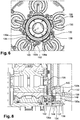
- the stator 132 is visible in perspective at the figure 2 , in cross section at the figure 6 and in axial section at the figure 8 . It has a symmetry of revolution about an axis, which is the axis A of rotation of the planet carrier and therefore of the impeller 130.
- the stator 132 comprises a cylindrical portion 134 which is intended to be surrounded by the impeller 130.
- the stator 132 comprises oil circulation pipes 136 which open out through orifices 136a on the external cylindrical surface 137 of the stator 132 with a view to the projection of lubricant radially outwards.
- the spinning wheel 130 comprises several parts visible at the figure 2 . These parts are integral with one another and intended to be integral with the planet carrier and therefore driven in rotation around the axis A. They therefore form a rotor which rotates around the aforementioned stator 132.
- the impeller 130 comprises a radially internal part 130a and a radially external part 130b which extends around the radially internal part.
- the radially internal part 130a has an annular shape extending around the axis A. It comprises at its internal periphery an annular groove 138 opening radially inwards. It comprises at its outer periphery an outer cylindrical surface 140.
- dynamic sealing annular seals 142, 144 On either side of the groove 138, that is to say upstream and downstream of the groove 138, are arranged dynamic sealing annular seals 142, 144, which are configured to cooperate with the rotor 132 .
- the radially internal part 130a comprises a middle part 130aa with a cross section in the shape of an inverted U. From this middle part 130aa extend respectively upstream and downstream of the cylindrical flanges 130ab supporting the seals 142, 144.
- the outer part 130b is mounted on the upstream cylindrical flange 130ab of the radially inner part 130a.
- Bosses 146 are located projecting on the outer cylindrical surface 140 of the part 130a.
- Substantially radial channels 148 pass through part 130a and extend between the bottom of groove 138 and surface 140, for the passage of lubricant.
- Substantially radial conduits 150 are further formed in part 130a and extend between the bottom of groove 138 and internal cavities 152 of bosses 146.
- the cavities 152 open out axially and are intended to receive the first longitudinal ends of nozzles 154 of lubricant.
- Lubricant contained in throat 138 may in operation flow to channels 148 and conduits 150.
- Conduits 150 supply lubricant to cavities 152 and nozzles 154, which are configured to spray lubricant onto the toothings of the planet wheels and solar power from the reducer.
- the channels 148 open out through orifices 148a on the surface 140 of the internal part 130a.
- the radially outer part 130b extends around this surface 140.
- the radially outer part 130b has an annular shape extending around the axis A. It comprises arms 156 extending substantially radially outwardly and which include at their radially outer ends means for supporting the axes of the satellites. These support means for each arm 156 comprise for example a cylindrical rim 158 oriented axially and around which an axial end 159 is intended to be mounted ( figure 6 ) of an axis of satellites.
- the cylindrical rim 158 internally defines a chamber 158a which is supplied with lubricant by a substantially radial passage 160 formed in the arm 156 ( figure 5 ).
- This passage 160 therefore communicates at its radially outer end with the chamber 158a, and at its radially inner end with a cup 162 of curved shape, the concavity of which is oriented radially inward ( figures 5 and 7 ).
- the arms 156 are aligned radially with the channels 148 and the orifices 148a of the latter are aligned with the cups 162.
- the lubricant leaving the orifices 148a is projected towards the cups. 162 which, by virtue of their shape, conveys the lubricant to the passages 160.
- the lubricant is then conveyed to the chambers 158a with a view to supplying the axles 159 and the planet bearings.
- the radially internal ends of the arms are radially spaced apart by a predetermined clearance J from the surface 140 of the internal part 130a.
- This set makes it possible to connect the pockets 162a defined by the bowls 162 to the external atmosphere in which the reducer is located. This makes it possible to make this lubrication independent of the lubrication of the nozzles 154 which, as we have seen, benefits from the additional pressure. generated by the centrifugal field which is added to the pressure of the lubricant supply pump of the pipes 136 of the stator 132.
- the invention thus combines the pressure supplied by the reducer feed pump with the centrifugal pressure generated by the rotor to more easily reach the meshes.
Landscapes
- Engineering & Computer Science (AREA)
- General Engineering & Computer Science (AREA)
- Mechanical Engineering (AREA)
- General Details Of Gearings (AREA)
Description
La présente invention concerne notamment un réducteur de vitesse à train épicycloïdal de turbomachine comprenant un rouet.The present invention relates in particular to a speed reducer with a planetary gear train for a turbomachine comprising an impeller.
Un réducteur de vitesse à train épicycloïdal d'une turbomachine d'aéronef comprend classiquement un solaire accouplé à un premier arbre et une couronne s'étendant autour du solaire. Des satellites sont disposés entre le solaire et la couronne et sont engrenés avec eux et portés par un porte-satellites accouplé à un second arbre.A planetary gear speed reducer of an aircraft turbomachine conventionally comprises a sun gear coupled to a first shaft and a crown extending around the sun. Satellites are arranged between the solar and the crown and are meshed with them and carried by a planet carrier coupled to a second shaft.
La
Le rouet 20 est solidaire du porte-satellites 10 du fait de sa liaison aux axes 16 de support des satellites 18. Le rouet 20 est donc destiné à être mis en rotation en fonctionnement autour de l'axe A et former ainsi un rotor du réducteur.The spinning
Le rouet 20 a une forme générale annulaire autour de l'axe A et comporte à sa périphérie externe des moyens de support des axes 16 de rotation des satellites 18. Le rouet 20 comprend en outre des moyens de lubrification des paliers montés entre les axes 16 et les satellites 18, et des dents d'engrènement des satellites 18 et du solaire 22. Ces moyens de lubrification comportent une gorge annulaire 24 située à la périphérie interne du rouet et débouchant radialement vers l'intérieur.The
Des injecteurs de lubrifiant, portés par un stator du réducteur ou de la turbomachine, sont disposés radialement à l'intérieur du rouet (ils ne sont pas représentés dans la
Le lubrifiant est amené jusqu'aux injecteurs par une pompe d'un groupe de lubrification de la turbomachine, qui délivre un débit prédéterminé de lubrifiant aux injecteurs. Avec la technologie actuelle décrite ci-dessus, le lubrifiant projeté dans la gorge est acheminé jusqu'aux moyens d'alimentation et/ou de lubrification par effet centrifuge uniquement. Cependant, on constate en pratique que les dentures des satellites et du solaire peuvent ne pas être suffisamment alimentées en lubrifiant, ce qui est problématique. Cette sous-alimentation en huile peut être due à un manque d'énergie suffisante transmise au fluide par effet centrifuge, ou à une répartition d'huile instable dans le rouet. Un phénomène d'aspiration d'huile des paliers peut notamment diminuer le débit d'huile alimentant les dentures.The lubricant is supplied to the injectors by a pump of a turbomachine lubrication unit, which delivers a predetermined flow rate of lubricant to the injectors. With the current technology described above, the lubricant projected in the throat is conveyed to the supply and / or lubrication means by centrifugal effect only. However, it is observed in practice that the toothings of the satellites and of the solar panel may not be sufficiently supplied with lubricant, which is problematic. This under-supply of oil may be due to a lack of sufficient energy transmitted to the fluid by centrifugal effect, or to an unstable distribution of oil in the impeller. A phenomenon of oil suction from the bearings can in particular reduce the flow of oil supplied to the teeth.
On a déjà proposé de pallier au problème de répartition d'huile dans le rouet en prévoyant deux gorges annulaires distinctes à la périphérie interne du rouet, qui sont alimentées indépendamment l'une de l'autre et alimentent respectivement les moyens d'alimentation et/ou de pulvérisation de lubrifiant des dentures d'une part, et des axes des satellites d'autre part. Cependant, ce type de rouet est complexe, coûteux à réaliser, et ne répond pas au manque d'énergie apportée au fluide pour atteindre les denturesIt has already been proposed to alleviate the problem of oil distribution in the impeller by providing two distinct annular grooves at the internal periphery of the impeller, which are supplied independently of one another and respectively supply the supply means and / or spraying the toothings with lubricant on the one hand, and the planet axles on the other hand. However, this type of impeller is complex, expensive to produce, and does not respond to the lack of energy supplied to the fluid to reach the teeth
Une solution existante propose de récupérer la pression d'huile moteur en ajoutant deux joints dynamiques de part et d'autre de la gorge annulaire. Cette solution permet de coupler la pression centrifuge générée par le rouet et la pression d'huile fournie par le moteur. Cependant, cette solution ne permet pas de ségréger l'huile allant aux paliers et l'huile allant aux dentures. La répartition d'huile reste instable dans le rouet.An existing solution proposes to recover the engine oil pressure by adding two dynamic seals on either side of the annular groove. This solution makes it possible to couple the centrifugal pressure generated by the impeller and the oil pressure supplied by the engine. However, this solution does not make it possible to segregate the oil going to the bearings and the oil going to the teeth. The oil distribution remains unstable in the impeller.
La présente invention propose un perfectionnement à ces technologies, qui apporte une solution simple, efficace et économique au problème de lubrification des dentures des satellites et du solaire d'un réducteur à train épicycloïdal.The present invention provides an improvement to these technologies, which provides a simple, effective and economical solution to the problem of lubricating the toothings of the planet wheels and of the sun gear of a planetary gear reducer.
Conformément à l'invention, on parvient à cet objectif avec un réducteur de vitesse à train épicycloïdal de turbomachine comprenant un porte-satellites avec un rouet, ledit rouet étant destiné à être solidaire en rotation dudit porte-satellites et à être mis en rotation autour d'un axe A dudit réducteur, ledit rouet ayant une forme générale annulaire autour dudit axe et comportant des moyens de support d'axes de rotation de satellites dudit réducteur, ledit rouet comportant des moyens de lubrification de dentures desdits satellites et de paliers desdits axes, lesdits moyens de lubrification comportant une gorge annulaire située à la périphérie interne dudit rouet et débouchant radialement vers l'intérieur, ladite gorge étant reliée à des moyens d'alimentation et/ou de pulvérisation de lubrifiant, caractérisé en ce que le rouet comporte des moyens annulaires d'étanchéité dynamique situés à la périphérie interne dudit rouet, de part et d'autre de ladite gorge, et configurés pour coopérer avec un stator du réducteur ou de la turbomachine destiné d'une part à s'étendre à l'intérieur du rouet et coaxialement à ce dernier et d'autre part à alimenter en lubrifiant ladite gorge.According to the invention, this objective is achieved with a speed reducer with a planetary gear train of a turbomachine comprising a planet carrier with a spinning wheel, said impeller being intended to be integral in rotation with said planet carrier and to be rotated around of an axis A of said reduction gear, said impeller having a general annular shape around said axis and comprising means for supporting the axes of rotation of the planetary gears of said reduction gear, said impeller comprising means for lubricating the teeth of said planetary gears and bearings of said axes , said lubrication means comprising an annular groove located at the internal periphery of said impeller and opening radially inwards, said groove being connected to means for supplying and / or spraying lubricant, characterized in that the impeller comprises annular dynamic sealing means located at the internal periphery of said impeller, on either side of said groove, and configured to cooperate with a stator of the reduction gear or of the turbomachine intended on the one hand to extend inside the impeller and coaxially with the latter and on the other hand to supply said groove with lubricant.
Contrairement à la technologie antérieure, des moyens d'étanchéité dynamique sont prévus entre le rouet formant rotor, et le stator qui alimente en lubrifiant le rouet. Par définition, ces moyens d'étanchéité sont destinés à assurer une étanchéité entre le rotor (rouet) et le stator en fonctionnement. Cette étanchéité est importante pour que le débit ou la pression de lubrifiant fourni pas la pompe d'alimentation en lubrifiant du stator soit conservé dans les moyens de lubrification du rouet. De plus, la coopération à étanchéité du rotor et du stator permet en outre à l'ensemble de fonctionner comme une pompe additionnelle additionnant au débit précité de la pompe les effets du champ centrifuge généré par cette pompe additionnelle, et ainsi d'assurer une lubrification optimale des dentures des satellites et du solaire, et des paliers des axes de satellites.Unlike the prior technology, dynamic sealing means are provided between the impeller forming the rotor, and the stator which supplies the impeller with lubricant. By definition, these sealing means are intended to ensure a seal between the rotor (impeller) and the stator in operation. This sealing is important so that the lubricant flow or pressure supplied by the stator lubricant feed pump is retained in the impeller lubrication means. In addition, the sealed cooperation of the rotor and the stator also allows the assembly to function as an additional pump adding to the aforementioned flow rate of the pump the effects of the centrifugal field generated by this additional pump, and thus to provide lubrication. optimal toothing of satellites and solar, and bearings of the axes of satellites.
Le porte-satellites selon l'invention peut comprendre une ou plusieurs des caractéristiques suivantes, prises isolément les unes des autres, ou en combinaison les unes avec les autres :
- le rouet est réalisé en deux parties annulaires, respectivement radialement externe est interne, s'étendant sensiblement l'une autour de l'autre, ladite partie radialement externe comprenant lesdits moyens de support et ladite partie radialement interne comprenant ladite gorge et portant lesdits moyens d'étanchéité ;
- ladite partie radialement interne comporte des canaux sensiblement radiaux et des conduits sensiblement radiaux de passage de lubrifiant, dont les extrémités radialement internes débouchent dans ladite gorge ;
- lesdits canaux et lesdits conduits sont régulièrement répartis autour dudit axe, chacun desdits canaux étant disposé entre deux conduits adjacents et chacun desdits conduits étant disposés entre deux canaux adjacents ;
- lesdits canaux débouchent à leurs extrémités radialement externes sur une surface cylindrique externe de ladite partie radialement interne, qui est destinée à être au moins en partie recouverte par ladite partie radialement externe ;
- lesdits conduits sont en communication fluidique avec des premières extrémités longitudinales de gicleurs de lubrifiant, qui sont montés en porte-à-faux à la périphérie externe de ladite partie radialement externe ;
- lesdites premières extrémités longitudinales desdits gicleurs sont montés dans des cavités de bossages situés sur ladite surface cylindrique externe de la partie radialement interne ;
- ladite partie radialement externe comprend des bras sensiblement radiaux comportant ou portant à leurs extrémités radialement externes lesdits moyens de support,
- lesdits bras sont alignés radialement avec lesdits canaux et comprennent des passages configurés pour être alimentés en lubrifiant sortant desdits canaux et s'étendant sensiblement radialement jusqu'auxdits moyens de support ;
- lesdits bras comprennent à leurs extrémités radialement internes des cuvettes incurvées dont la concavité est orientée radialement vers l'intérieur, pour la récupération de lubrifiant sortant desdits canaux et son acheminent jusqu'auxdits passages ;
- lesdites extrémités radialement internes desdits bras sont écartées d'un jeu radial prédéterminé de ladite surface cylindrique externe afin d'assurer une communication fluidique avec l'environnement extérieur.
- the impeller is made in two annular parts, respectively radially outer and inner, extending substantially around one another, said radially outer part comprising said support means and said radially inner part comprising said groove and bearing said means of sealing;
- said radially internal part comprises substantially radial channels and substantially radial lubricant passage conduits, the radially internal ends of which open into said groove;
- said channels and said conduits are regularly distributed around said axis, each of said channels being arranged between two adjacent conduits and each of said conduits being arranged between two adjacent channels;
- said channels open at their radially outer ends onto an outer cylindrical surface of said radially inner part, which is intended to be at least partly covered by said radially outer part;
- said conduits are in fluid communication with first longitudinal ends of lubricant nozzles, which are cantilevered at the outer periphery of said radially outer portion;
- said first longitudinal ends of said nozzles are mounted in boss cavities located on said outer cylindrical surface of the radially inner part;
- said radially outer part comprises substantially radial arms comprising or carrying at their radially outer ends said support means,
- said arms are radially aligned with said channels and include passages configured to be supplied with lubricant emerging from said channels and extending substantially radially to said support means;
- said arms comprise at their radially inner ends curved cups, the concavity of which is oriented radially inwards, for the recovery of lubricant leaving said channels and its conveyance to said passages;
- said radially inner ends of said arms are spaced apart by a predetermined radial clearance from said outer cylindrical surface in order to provide fluid communication with the external environment.
La présente invention concerne également une turbomachine comportant un réducteur de vitesse à train épicycloïdal tel que décrit ci-dessus.The present invention also relates to a turbomachine comprising a speed reducer with epicyclic train as described above.
D'autres caractéristiques et avantages ressortiront de la description qui suit d'un mode de réalisation non limitatif de l'invention en référence aux dessins annexés sur lesquels :
- la
figure 1 est une vue schématique en perspective d'un porte-satellites de la technique antérieure, - la
figure 2 est une vue schématique éclatée et en perspective d'un stator, d'un rouet de porte-satellites selon l'invention ainsi que ses gicleurs, - la
figure 3 est une vue schématique en perspective du stator de lafigure 2 ; - la
figure 4 est une vue schématique en perspective du rouet du porte-satellites de lafigure 2 ; - la
figure 5 est une vue schématique partielle, en coupe axiale, et à plus grande échelle du rouet de lafigure 4 ; - la
figure 6 est une vue schématique partielle en coupe transversale du stator et du rouet de lafigure 2 ; - la
figure 7 est une vue à plus grand échelle d'un détail de lafigure 6 ; - la
figure 8 est une vue schématique partielle en coupe axiale du stator et du rouet de lafigure 2 .
- the
figure 1 is a schematic perspective view of a planetary carrier of the prior art, - the
figure 2 is an exploded schematic view in perspective of a stator, of a planet carrier impeller according to the invention as well as its jets, - the
figure 3 is a schematic perspective view of the stator of thefigure 2 ; - the
figure 4 is a schematic perspective view of the spinning wheel of the planet carrier of thefigure 2 ; - the
figure 5 is a partial schematic view, in axial section, and on a larger scale of the impeller of thefigure 4 ; - the
figure 6 is a partial schematic view in cross section of the stator and the impeller of thefigure 2 ; - the
figure 7 is a view on a larger scale of a detail of thefigure 6 ; - the
figure 8 is a partial schematic view in axial section of the stator and the impeller of thefigure 2 .
La
L'invention concerne le domaine des porte-satellites de réducteurs de vitesse à train épicycloïdal de turbomachine, en particulier d'aéronef. La
L'invention vise plus particulièrement un rouet pour un tel porte-satellites. Un rouet de porte-satellites est une pièce permettant notamment de distribuer un lubrifiant, tel que de l'huile, dans différentes zones sensibles à une élévation thermique et au frottement sec au sein du réducteur. Le rouet possède deux principales zones de distribution d'huile : les engrènements ou dentures du solaire et des satellites et les paliers des satellites.The invention relates more particularly to a spinning wheel for such a planet carrier. A planet carrier spinning wheel is a part making it possible in particular to distribute a lubricant, such as oil, in various areas sensitive to thermal rise and to dry friction within the reducer. The impeller has two main oil distribution areas: the meshes or teeth of the solar and the planet wheels and the planet bearings.
La
Le stator 132 est visible en perspective à la
Le stator 132 comprend une portion cylindrique 134 qui est destinée à être entourée par le rouet 130. Comme cela est visible à la
Le rouet 130 comprend plusieurs pièces visibles à la
Parmi les pièces du rouet 130, il comprend une partie radialement interne 130a et une partie radialement externe 130b qui s'étend autour de la partie radialement interne.Among the parts of the
La partie radialement interne 130a a une forme annulaire s'étendant autour de l'axe A. Elle comprend à sa périphérie interne une gorge annulaire 138 débouchant radialement vers l'intérieur. Elle comprend à sa périphérie externe une surface cylindrique externe 140.The radially
De part et d'autre de la gorge 138, c'est-à-dire en amont et en aval de la gorge 138, sont disposés des joints annulaires d'étanchéité dynamique 142, 144, qui sont configurés pour coopérer avec le rotor 132.On either side of the
Dans l'exemple représenté, la partie radialement interne 130a comprend une partie médiane 130aa à section transversale en forme de U inversé. De cette partie médiane 130aa s'étendent respectivement vers l'amont et vers l'aval des rebords cylindriques 130ab de support des joints 142, 144.. La partie externe 130b est montée sur le rebord cylindrique amont 130ab de la partie radialement interne 130a.In the example shown, the radially
Des bossages 146 sont situés en saillie sur la surface cylindrique externe 140 de la partie 130a. Des canaux 148 sensiblement radiaux traversent la partie 130a et s'étendent entre le fond de la gorge 138 et la surface 140, pour le passage de lubrifiant. Des conduits 150 sensiblement radiaux sont en outre formés dans la partie 130a et s'étendent entre le fond de la gorge 138 et des cavités internes 152 des bossages 146.
Les cavités 152 débouchent axialement et sont destinées à recevoir des premières extrémités longitudinales de gicleurs 154 de lubrifiant. Du lubrifiant contenu dans la gorge 138 peut en fonctionnement s'écouler jusqu'aux canaux 148 et aux conduits 150. Les conduits 150 alimentent en lubrifiant les cavités 152 et les gicleurs 154, qui sont configurés pour pulvériser du lubrifiant sur les dentures des satellites et du solaire du réducteur.The
Les canaux 148 débouchent par des orifices 148a sur la surface 140 de la partie interne 130a. La partie radialement externe 130b s'étend autour de cette surface 140.The
La partie radialement externe 130b a une forme annulaire s'étendant autour de l'axe A. Elle comprend des bras 156 s'étendant sensiblement radialement vers l'extérieur et qui comprennent à leurs extrémités radialement externes des moyens de support des axes des satellites. Ces moyens de support de chaque bras 156 comprennent par exemple un rebord cylindrique 158 orienté axialement et autour duquel est destinée à être montée une extrémité axiale 159 (
Le rebord cylindrique 158 définit intérieurement une chambre 158a qui est alimentée en lubrifiant par un passage 160 sensiblement radial formé dans le bras 156 (
En position montée de la partie externe 130b sur la partie interne 130a, les bras 156 sont alignés radialement avec les canaux 148 et les orifices 148 a de ces derniers sont alignés avec les cuvettes 162. Le lubrifiant sortant des orifices 148a est projeté vers les cuvettes 162 qui, grâce à leur forme, achemine le lubrifiant jusqu'aux passages 160. Le lubrifiant est ensuite acheminé jusqu'aux chambres 158a en vue de l'alimentation des axes159 et des paliers des satellites.In the mounted position of the
Comme on le voit à la
L'invention combine ainsi la pression fournie par la pompe d'alimentation du réducteur à la pression centrifuge générée par le rotor pour atteindre plus facilement les engrènements.The invention thus combines the pressure supplied by the reducer feed pump with the centrifugal pressure generated by the rotor to more easily reach the meshes.
Comme décrit dans ce qui précède, le lubrifiant passe par plusieurs étapes avant de cibler les postes de pertes et les postes à lubrifier :
- après avoir traversé le stator 132, le lubrifiant arrive dans le rotor (rouet 130) par le biais des canalisations 136 dirigées radialement ; le lubrifiant arrive sous pression grâce aux joints dynamiques 142, 144 assurant l'étanchéité entre le rotor et le stator ;
- une fois arrivé dans le rotor, le lubrifiant est soumis au champ centrifuge ; le rotor se comporte comme une pompe s'additionnant à la pression du groupe de lubrification au champ centrifuge généré par sa propre rotation ; ici, le débit de lubrifiant se répartit entre les gicleurs de lubrification des dentures et les paliers, en fonction des pertes de charge des circuits ;
- après avoir traversé les canaux 148, le lubrifiant est remis à la pression atmosphérique ; le jeu J évite que le phénomène de pompage affecte la lubrification des paliers ;
- le lubrifiant allant aux paliers est ensuite entrainé par le champ centrifuge du rotor.
- after having passed through the
stator 132, the lubricant arrives in the rotor (impeller 130) through thepipes 136 directed radially; the lubricant arrives under pressure thanks to thedynamic seals - once it has entered the rotor, the lubricant is subjected to the centrifugal field; the rotor behaves like a pump adding to the pressure of the lubrication group in the centrifugal field generated by its own rotation; here, the lubricant flow is distributed between the toothing lubrication jets and the bearings, as a function of the pressure drops in the circuits;
- after passing through the
channels 148, the lubricant is returned to atmospheric pressure; the clearance J prevents the pumping phenomenon from affecting the lubrication of the bearings; - the lubricant going to the bearings is then entrained by the centrifugal field of the rotor.
Claims (10)
- Planetary gear speed reducer of a turbine engine comprising a planet carrier with an impeller (130), said impeller (130) being intended to be integral in rotation with said planet carrier and to be set into rotation around an axis A of said reducer, said impeller having an annular shape around said axis and comprising means (158) for supporting axes (151) of rotation of planets of said reducer, said impeller comprising means for lubricating teeth of said planets and bearings of said axes, said lubrication means comprising an annular groove (138) located on the internal periphery of said impeller and opening radially towards the inside, said groove being connected to lubricant supply and/or spray means, characterised in that the impeller comprises dynamic annular sealing means (142, 144) located at the inner periphery of said impeller, on either side of said groove, and configured to interact with a stator (132) of the reducer or of the turbine engine intended to extend inside of and coaxially with the latter.
- Planetary gear speed reducer according to the preceding claim, wherein said impeller is made of two annular portions, respectively radially external (130b) and internal (130a), extending substantially around one another, said radially external portion comprising said means for supporting (158) and said radially internal portion comprising said groove (138) and carrying said sealing means (142, 144).
- Planetary gear speed reducer according to the preceding claim, wherein said radially internal portion (130a) comprises substantially radial channels (148) and substantially radial ducts (150) for the passage of lubricant, of which the radially internal ends open into said groove (138).
- Planetary gear speed reducer according to the preceding claim, wherein said channels (148) open at the radially external ends thereof onto an external cylindrical surface (140) of said radially internal portion (130a), which is intended to be at least partially covered by said radially external part (130b).
- Planetary gear speed reducer according to claim 3 or 4, wherein said ducts (150) are in fluidic communication with first longitudinal ends of lubricant nozzles (154), which are cantilever-mounted at the outer periphery of said radially external portion (130b).
- Planetary gear speed reducer according to one of claims 2 to 5, wherein said radially external portion (130b) comprises substantially radial arms (156) comprising or carrying, at the radially external ends thereof, said means for supporting (158).
- Planetary gear speed reducer according to the preceding claim, dependent on claim 4, wherein said arms (156) are radially aligned with said channels (148) and comprise passages (160) configured to be supplied with lubricant exiting from said channels and extending substantially radially to said means for supporting (158).
- Planetary gear speed reducer according to the preceding claim, wherein said arms (156) comprise, at the radially internal ends thereof, curved wells (162) of which the concavity is oriented radially towards the inside, for the recovery of lubricant exiting from said channels (148) and the conveyance thereof to said passages (160).
- Planetary gear speed reducer according to the preceding claim, wherein said radially internal ends of said arms (156) are separated by a predetermined radial clearance (J) from said external cylindrical surface (140) in order to ensure a fluidic communication with the outside environment.
- Aircraft turbine engine, characterised in that it comprises a planetary gear speed reducer such as defined in one of claims 1 to 9.
Applications Claiming Priority (2)
| Application Number | Priority Date | Filing Date | Title |
|---|---|---|---|
| FR1752991A FR3065046B1 (en) | 2017-04-06 | 2017-04-06 | WHEEL FOR TURBOMACHINE EPICYCLOIDAL TRAIN SPEED REDUCER SATELLITE HOLDERS |
| PCT/EP2018/058647 WO2018185186A1 (en) | 2017-04-06 | 2018-04-04 | Impeller for a planet carrier of a planetary gear speed reducer of a turbomachine |
Publications (2)
| Publication Number | Publication Date |
|---|---|
| EP3607228A1 EP3607228A1 (en) | 2020-02-12 |
| EP3607228B1 true EP3607228B1 (en) | 2021-12-01 |
Family
ID=59859140
Family Applications (1)
| Application Number | Title | Priority Date | Filing Date |
|---|---|---|---|
| EP18717875.1A Active EP3607228B1 (en) | 2017-04-06 | 2018-04-04 | Planetary gear speed reducer of a turbomachine with a planet carrier |
Country Status (6)
| Country | Link |
|---|---|
| US (1) | US11231104B2 (en) |
| EP (1) | EP3607228B1 (en) |
| JP (1) | JP2020516819A (en) |
| CN (1) | CN110475993B (en) |
| FR (1) | FR3065046B1 (en) |
| WO (1) | WO2018185186A1 (en) |
Families Citing this family (8)
| Publication number | Priority date | Publication date | Assignee | Title |
|---|---|---|---|---|
| FR3088979B1 (en) * | 2018-11-23 | 2021-06-18 | Safran Trans Systems | SATELLITE CARRIER FOR AN AIRCRAFT TURBOMACHINE MECHANICAL REDUCER |
| GB201907074D0 (en) * | 2019-05-20 | 2019-07-03 | Rolls Royce Plc | Gas turbine engine |
| FR3103241B1 (en) | 2019-11-15 | 2021-12-17 | Safran Trans Systems | WHEEL FOR A TURBOMACHINE EPICYCLOIDAL GEAR GEAR REDUCER SATELLITE CARRIER |
| FR3103240B1 (en) | 2019-11-15 | 2022-07-15 | Safran Aircraft Engines | IMPELLER FOR A TURBOMACHINE EPICYCLOIDAL GEAR SPEED REDUCER SATELLITE CARRIER |
| FR3119431A1 (en) * | 2021-02-03 | 2022-08-05 | Safran Transmission Systems | Mechanical reducer |
| CN113606323B (en) * | 2021-08-12 | 2022-10-28 | 滁州学院 | Lubricating device of alternative operation type RV reducer |
| FR3128753B1 (en) | 2021-11-03 | 2023-11-24 | Safran Trans Systems | MECHANICAL SPEED REDUCER FOR AN AIRCRAFT TURBOMACHINE |
| IT202200017376A1 (en) * | 2022-08-17 | 2024-02-17 | Ge Avio Srl | FLOATING OIL COLLECTOR FOR PLANETARY GEAR SYSTEMS |
Family Cites Families (7)
| Publication number | Priority date | Publication date | Assignee | Title |
|---|---|---|---|---|
| EP2078888A1 (en) * | 2008-01-10 | 2009-07-15 | Gamesa Innovation & Technology, S.L. | A sealing for use in a lubrication system |
| DE102010060147B4 (en) * | 2010-10-25 | 2017-03-09 | Eickhoff Antriebstechnik Gmbh | Planetary gear with a central distributor |
| FR3009594B1 (en) * | 2013-08-08 | 2016-12-09 | Snecma | EPICYCLOIDAL TRAIN REDUCER WITH FLUID TRANSFER PIPES, AND AIRCRAFT TURBOMACHINE (S) FOR AN AIRCRAFT WITH SUCH REDUCER |
| US9382997B2 (en) * | 2014-07-24 | 2016-07-05 | Deere & Company | Gear set lubrication system and method |
| FR3036763B1 (en) * | 2015-05-27 | 2017-05-26 | Hispano-Suiza | EPICYCLOIDAL TRAIN REDUCER |
| JP6498559B2 (en) * | 2015-07-31 | 2019-04-10 | 川崎重工業株式会社 | Lubrication structure for planetary gear unit |
| ITUA20162735A1 (en) * | 2016-04-20 | 2017-10-20 | Ge Avio Srl | OIL TRANSFER UNIT TO TRANSFER OIL BETWEEN A STATIC PART AND A ROTATING PART |
-
2017
- 2017-04-06 FR FR1752991A patent/FR3065046B1/en active Active
-
2018
- 2018-04-04 EP EP18717875.1A patent/EP3607228B1/en active Active
- 2018-04-04 CN CN201880023379.4A patent/CN110475993B/en active Active
- 2018-04-04 WO PCT/EP2018/058647 patent/WO2018185186A1/en unknown
- 2018-04-04 US US16/500,371 patent/US11231104B2/en active Active
- 2018-04-04 JP JP2019554506A patent/JP2020516819A/en active Pending
Non-Patent Citations (1)
| Title |
|---|
| None * |
Also Published As
| Publication number | Publication date |
|---|---|
| US20210116017A1 (en) | 2021-04-22 |
| FR3065046B1 (en) | 2019-04-19 |
| CN110475993B (en) | 2023-03-17 |
| EP3607228A1 (en) | 2020-02-12 |
| CN110475993A (en) | 2019-11-19 |
| WO2018185186A1 (en) | 2018-10-11 |
| JP2020516819A (en) | 2020-06-11 |
| FR3065046A1 (en) | 2018-10-12 |
| US11231104B2 (en) | 2022-01-25 |
Similar Documents
| Publication | Publication Date | Title |
|---|---|---|
| EP3607228B1 (en) | Planetary gear speed reducer of a turbomachine with a planet carrier | |
| EP3615848B1 (en) | Cage planet carrier for a speed-reducing unit with an epicyclic gear train | |
| EP3710727B1 (en) | Turbomachine speed reducer with planetary gear set | |
| EP3495692B1 (en) | Turbine engine speed reduction ring gear with planetary gear | |
| CA2938385C (en) | Turbine engine provided with a lubrication unit | |
| CA2640040C (en) | Gear assembly system | |
| FR2942284A1 (en) | LUBRICATION AND COOLING OF AN EPICYCLOIDAL GEAR TRAIN REDUCER | |
| EP3123059A1 (en) | Transmission assembly including a transmission member and an oil distribution system | |
| FR3036763A1 (en) | EPICYCLOIDAL TRAIN REDUCER | |
| EP3726097A1 (en) | Mechanical gear for aircraft turbine engine | |
| EP3610176A1 (en) | Assembly comprising a planetary gearset | |
| FR3027625A1 (en) | TURBOMACHINE COMPRISING AN ELECTRIC CURRENT GENERATOR FOR THE INJECTION OF OIL FROM THE INTERIOR OF A TURBINE TREE | |
| EP3822516A1 (en) | Stage impeller for supplying oil to an epicyclic or planetary reduction gear | |
| EP3610177A1 (en) | Planetary gearset | |
| EP3807508B1 (en) | Rotary planet carrier for a mechanical reduction gear of a turbomachine | |
| EP3610175B1 (en) | Lubrication for a planetary gearset | |
| EP3807507B1 (en) | Device for oil distribution for a rotating planet carrier of a step-down gear of a turbomachine | |
| EP3822515B1 (en) | Impeller for a planet carrier of a speed reducer with epicyclic gearset of a turbomachine | |
| EP4023909B1 (en) | Planet carrier for a gearbox of an aircraft turbine engine |
Legal Events
| Date | Code | Title | Description |
|---|---|---|---|
| STAA | Information on the status of an ep patent application or granted ep patent |
Free format text: STATUS: UNKNOWN |
|
| STAA | Information on the status of an ep patent application or granted ep patent |
Free format text: STATUS: THE INTERNATIONAL PUBLICATION HAS BEEN MADE |
|
| PUAI | Public reference made under article 153(3) epc to a published international application that has entered the european phase |
Free format text: ORIGINAL CODE: 0009012 |
|
| STAA | Information on the status of an ep patent application or granted ep patent |
Free format text: STATUS: REQUEST FOR EXAMINATION WAS MADE |
|
| 17P | Request for examination filed |
Effective date: 20191016 |
|
| AK | Designated contracting states |
Kind code of ref document: A1 Designated state(s): AL AT BE BG CH CY CZ DE DK EE ES FI FR GB GR HR HU IE IS IT LI LT LU LV MC MK MT NL NO PL PT RO RS SE SI SK SM TR |
|
| AX | Request for extension of the european patent |
Extension state: BA ME |
|
| DAV | Request for validation of the european patent (deleted) | ||
| DAX | Request for extension of the european patent (deleted) | ||
| STAA | Information on the status of an ep patent application or granted ep patent |
Free format text: STATUS: EXAMINATION IS IN PROGRESS |
|
| STAA | Information on the status of an ep patent application or granted ep patent |
Free format text: STATUS: EXAMINATION IS IN PROGRESS |
|
| 17Q | First examination report despatched |
Effective date: 20201016 |
|
| GRAP | Despatch of communication of intention to grant a patent |
Free format text: ORIGINAL CODE: EPIDOSNIGR1 |
|
| STAA | Information on the status of an ep patent application or granted ep patent |
Free format text: STATUS: GRANT OF PATENT IS INTENDED |
|
| INTG | Intention to grant announced |
Effective date: 20210623 |
|
| GRAS | Grant fee paid |
Free format text: ORIGINAL CODE: EPIDOSNIGR3 |
|
| GRAA | (expected) grant |
Free format text: ORIGINAL CODE: 0009210 |
|
| STAA | Information on the status of an ep patent application or granted ep patent |
Free format text: STATUS: THE PATENT HAS BEEN GRANTED |
|
| AK | Designated contracting states |
Kind code of ref document: B1 Designated state(s): AL AT BE BG CH CY CZ DE DK EE ES FI FR GB GR HR HU IE IS IT LI LT LU LV MC MK MT NL NO PL PT RO RS SE SI SK SM TR |
|
| REG | Reference to a national code |
Ref country code: GB Ref legal event code: FG4D Free format text: NOT ENGLISH |
|
| REG | Reference to a national code |
Ref country code: AT Ref legal event code: REF Ref document number: 1452056 Country of ref document: AT Kind code of ref document: T Effective date: 20211215 Ref country code: CH Ref legal event code: EP |
|
| REG | Reference to a national code |
Ref country code: IE Ref legal event code: FG4D Free format text: LANGUAGE OF EP DOCUMENT: FRENCH |
|
| REG | Reference to a national code |
Ref country code: DE Ref legal event code: R096 Ref document number: 602018027477 Country of ref document: DE |
|
| REG | Reference to a national code |
Ref country code: LT Ref legal event code: MG9D |
|
| REG | Reference to a national code |
Ref country code: NL Ref legal event code: MP Effective date: 20211201 |
|
| REG | Reference to a national code |
Ref country code: AT Ref legal event code: MK05 Ref document number: 1452056 Country of ref document: AT Kind code of ref document: T Effective date: 20211201 |
|
| PG25 | Lapsed in a contracting state [announced via postgrant information from national office to epo] |
Ref country code: RS Free format text: LAPSE BECAUSE OF FAILURE TO SUBMIT A TRANSLATION OF THE DESCRIPTION OR TO PAY THE FEE WITHIN THE PRESCRIBED TIME-LIMIT Effective date: 20211201 Ref country code: LT Free format text: LAPSE BECAUSE OF FAILURE TO SUBMIT A TRANSLATION OF THE DESCRIPTION OR TO PAY THE FEE WITHIN THE PRESCRIBED TIME-LIMIT Effective date: 20211201 Ref country code: FI Free format text: LAPSE BECAUSE OF FAILURE TO SUBMIT A TRANSLATION OF THE DESCRIPTION OR TO PAY THE FEE WITHIN THE PRESCRIBED TIME-LIMIT Effective date: 20211201 Ref country code: BG Free format text: LAPSE BECAUSE OF FAILURE TO SUBMIT A TRANSLATION OF THE DESCRIPTION OR TO PAY THE FEE WITHIN THE PRESCRIBED TIME-LIMIT Effective date: 20220301 Ref country code: AT Free format text: LAPSE BECAUSE OF FAILURE TO SUBMIT A TRANSLATION OF THE DESCRIPTION OR TO PAY THE FEE WITHIN THE PRESCRIBED TIME-LIMIT Effective date: 20211201 |
|
| PG25 | Lapsed in a contracting state [announced via postgrant information from national office to epo] |
Ref country code: SE Free format text: LAPSE BECAUSE OF FAILURE TO SUBMIT A TRANSLATION OF THE DESCRIPTION OR TO PAY THE FEE WITHIN THE PRESCRIBED TIME-LIMIT Effective date: 20211201 Ref country code: PL Free format text: LAPSE BECAUSE OF FAILURE TO SUBMIT A TRANSLATION OF THE DESCRIPTION OR TO PAY THE FEE WITHIN THE PRESCRIBED TIME-LIMIT Effective date: 20211201 Ref country code: NO Free format text: LAPSE BECAUSE OF FAILURE TO SUBMIT A TRANSLATION OF THE DESCRIPTION OR TO PAY THE FEE WITHIN THE PRESCRIBED TIME-LIMIT Effective date: 20220301 Ref country code: LV Free format text: LAPSE BECAUSE OF FAILURE TO SUBMIT A TRANSLATION OF THE DESCRIPTION OR TO PAY THE FEE WITHIN THE PRESCRIBED TIME-LIMIT Effective date: 20211201 Ref country code: HR Free format text: LAPSE BECAUSE OF FAILURE TO SUBMIT A TRANSLATION OF THE DESCRIPTION OR TO PAY THE FEE WITHIN THE PRESCRIBED TIME-LIMIT Effective date: 20211201 Ref country code: GR Free format text: LAPSE BECAUSE OF FAILURE TO SUBMIT A TRANSLATION OF THE DESCRIPTION OR TO PAY THE FEE WITHIN THE PRESCRIBED TIME-LIMIT Effective date: 20220302 Ref country code: ES Free format text: LAPSE BECAUSE OF FAILURE TO SUBMIT A TRANSLATION OF THE DESCRIPTION OR TO PAY THE FEE WITHIN THE PRESCRIBED TIME-LIMIT Effective date: 20211201 |
|
| PG25 | Lapsed in a contracting state [announced via postgrant information from national office to epo] |
Ref country code: NL Free format text: LAPSE BECAUSE OF FAILURE TO SUBMIT A TRANSLATION OF THE DESCRIPTION OR TO PAY THE FEE WITHIN THE PRESCRIBED TIME-LIMIT Effective date: 20211201 |
|
| PG25 | Lapsed in a contracting state [announced via postgrant information from national office to epo] |
Ref country code: SM Free format text: LAPSE BECAUSE OF FAILURE TO SUBMIT A TRANSLATION OF THE DESCRIPTION OR TO PAY THE FEE WITHIN THE PRESCRIBED TIME-LIMIT Effective date: 20211201 Ref country code: SK Free format text: LAPSE BECAUSE OF FAILURE TO SUBMIT A TRANSLATION OF THE DESCRIPTION OR TO PAY THE FEE WITHIN THE PRESCRIBED TIME-LIMIT Effective date: 20211201 Ref country code: RO Free format text: LAPSE BECAUSE OF FAILURE TO SUBMIT A TRANSLATION OF THE DESCRIPTION OR TO PAY THE FEE WITHIN THE PRESCRIBED TIME-LIMIT Effective date: 20211201 Ref country code: PT Free format text: LAPSE BECAUSE OF FAILURE TO SUBMIT A TRANSLATION OF THE DESCRIPTION OR TO PAY THE FEE WITHIN THE PRESCRIBED TIME-LIMIT Effective date: 20220401 Ref country code: EE Free format text: LAPSE BECAUSE OF FAILURE TO SUBMIT A TRANSLATION OF THE DESCRIPTION OR TO PAY THE FEE WITHIN THE PRESCRIBED TIME-LIMIT Effective date: 20211201 Ref country code: CZ Free format text: LAPSE BECAUSE OF FAILURE TO SUBMIT A TRANSLATION OF THE DESCRIPTION OR TO PAY THE FEE WITHIN THE PRESCRIBED TIME-LIMIT Effective date: 20211201 |
|
| REG | Reference to a national code |
Ref country code: DE Ref legal event code: R097 Ref document number: 602018027477 Country of ref document: DE |
|
| PG25 | Lapsed in a contracting state [announced via postgrant information from national office to epo] |
Ref country code: IS Free format text: LAPSE BECAUSE OF FAILURE TO SUBMIT A TRANSLATION OF THE DESCRIPTION OR TO PAY THE FEE WITHIN THE PRESCRIBED TIME-LIMIT Effective date: 20220401 |
|
| PLBE | No opposition filed within time limit |
Free format text: ORIGINAL CODE: 0009261 |
|
| STAA | Information on the status of an ep patent application or granted ep patent |
Free format text: STATUS: NO OPPOSITION FILED WITHIN TIME LIMIT |
|
| PG25 | Lapsed in a contracting state [announced via postgrant information from national office to epo] |
Ref country code: DK Free format text: LAPSE BECAUSE OF FAILURE TO SUBMIT A TRANSLATION OF THE DESCRIPTION OR TO PAY THE FEE WITHIN THE PRESCRIBED TIME-LIMIT Effective date: 20211201 Ref country code: AL Free format text: LAPSE BECAUSE OF FAILURE TO SUBMIT A TRANSLATION OF THE DESCRIPTION OR TO PAY THE FEE WITHIN THE PRESCRIBED TIME-LIMIT Effective date: 20211201 |
|
| 26N | No opposition filed |
Effective date: 20220902 |
|
| PG25 | Lapsed in a contracting state [announced via postgrant information from national office to epo] |
Ref country code: SI Free format text: LAPSE BECAUSE OF FAILURE TO SUBMIT A TRANSLATION OF THE DESCRIPTION OR TO PAY THE FEE WITHIN THE PRESCRIBED TIME-LIMIT Effective date: 20211201 |
|
| REG | Reference to a national code |
Ref country code: CH Ref legal event code: PL |
|
| REG | Reference to a national code |
Ref country code: BE Ref legal event code: MM Effective date: 20220430 |
|
| PG25 | Lapsed in a contracting state [announced via postgrant information from national office to epo] |
Ref country code: MC Free format text: LAPSE BECAUSE OF FAILURE TO SUBMIT A TRANSLATION OF THE DESCRIPTION OR TO PAY THE FEE WITHIN THE PRESCRIBED TIME-LIMIT Effective date: 20211201 Ref country code: LU Free format text: LAPSE BECAUSE OF NON-PAYMENT OF DUE FEES Effective date: 20220404 Ref country code: LI Free format text: LAPSE BECAUSE OF NON-PAYMENT OF DUE FEES Effective date: 20220430 Ref country code: CH Free format text: LAPSE BECAUSE OF NON-PAYMENT OF DUE FEES Effective date: 20220430 |
|
| PG25 | Lapsed in a contracting state [announced via postgrant information from national office to epo] |
Ref country code: BE Free format text: LAPSE BECAUSE OF NON-PAYMENT OF DUE FEES Effective date: 20220430 |
|
| PG25 | Lapsed in a contracting state [announced via postgrant information from national office to epo] |
Ref country code: IE Free format text: LAPSE BECAUSE OF NON-PAYMENT OF DUE FEES Effective date: 20220404 |
|
| PG25 | Lapsed in a contracting state [announced via postgrant information from national office to epo] |
Ref country code: IT Free format text: LAPSE BECAUSE OF FAILURE TO SUBMIT A TRANSLATION OF THE DESCRIPTION OR TO PAY THE FEE WITHIN THE PRESCRIBED TIME-LIMIT Effective date: 20211201 |
|
| PG25 | Lapsed in a contracting state [announced via postgrant information from national office to epo] |
Ref country code: MK Free format text: LAPSE BECAUSE OF FAILURE TO SUBMIT A TRANSLATION OF THE DESCRIPTION OR TO PAY THE FEE WITHIN THE PRESCRIBED TIME-LIMIT Effective date: 20211201 Ref country code: CY Free format text: LAPSE BECAUSE OF FAILURE TO SUBMIT A TRANSLATION OF THE DESCRIPTION OR TO PAY THE FEE WITHIN THE PRESCRIBED TIME-LIMIT Effective date: 20211201 |
|
| PGFP | Annual fee paid to national office [announced via postgrant information from national office to epo] |
Ref country code: GB Payment date: 20240320 Year of fee payment: 7 |
|
| PG25 | Lapsed in a contracting state [announced via postgrant information from national office to epo] |
Ref country code: HU Free format text: LAPSE BECAUSE OF FAILURE TO SUBMIT A TRANSLATION OF THE DESCRIPTION OR TO PAY THE FEE WITHIN THE PRESCRIBED TIME-LIMIT; INVALID AB INITIO Effective date: 20180404 |
|
| PGFP | Annual fee paid to national office [announced via postgrant information from national office to epo] |
Ref country code: FR Payment date: 20240320 Year of fee payment: 7 |
|
| PGFP | Annual fee paid to national office [announced via postgrant information from national office to epo] |
Ref country code: DE Payment date: 20240320 Year of fee payment: 7 |