EP3607176B1 - Anschlussadapter zum anschluss einer behandlungseinrichtung an einen anschlusskopf einer behandlungsvorrichtung für insbesondere flüssige fluide, anschlusskopf und behandlungsvorrichtung - Google Patents
Anschlussadapter zum anschluss einer behandlungseinrichtung an einen anschlusskopf einer behandlungsvorrichtung für insbesondere flüssige fluide, anschlusskopf und behandlungsvorrichtung Download PDFInfo
- Publication number
- EP3607176B1 EP3607176B1 EP18718119.3A EP18718119A EP3607176B1 EP 3607176 B1 EP3607176 B1 EP 3607176B1 EP 18718119 A EP18718119 A EP 18718119A EP 3607176 B1 EP3607176 B1 EP 3607176B1
- Authority
- EP
- European Patent Office
- Prior art keywords
- connection
- connection adapter
- treatment device
- fluid
- section
- Prior art date
- Legal status (The legal status is an assumption and is not a legal conclusion. Google has not performed a legal analysis and makes no representation as to the accuracy of the status listed.)
- Active
Links
Images






Classifications
-
- F—MECHANICAL ENGINEERING; LIGHTING; HEATING; WEAPONS; BLASTING
- F01—MACHINES OR ENGINES IN GENERAL; ENGINE PLANTS IN GENERAL; STEAM ENGINES
- F01M—LUBRICATING OF MACHINES OR ENGINES IN GENERAL; LUBRICATING INTERNAL COMBUSTION ENGINES; CRANKCASE VENTILATING
- F01M11/00—Component parts, details or accessories, not provided for in, or of interest apart from, groups F01M1/00 - F01M9/00
- F01M11/03—Mounting or connecting of lubricant purifying means relative to the machine or engine; Details of lubricant purifying means
-
- B—PERFORMING OPERATIONS; TRANSPORTING
- B01—PHYSICAL OR CHEMICAL PROCESSES OR APPARATUS IN GENERAL
- B01D—SEPARATION
- B01D27/00—Cartridge filters of the throw-away type
- B01D27/08—Construction of the casing
-
- B—PERFORMING OPERATIONS; TRANSPORTING
- B01—PHYSICAL OR CHEMICAL PROCESSES OR APPARATUS IN GENERAL
- B01D—SEPARATION
- B01D35/00—Filtering devices having features not specifically covered by groups B01D24/00 - B01D33/00, or for applications not specifically covered by groups B01D24/00 - B01D33/00; Auxiliary devices for filtration; Filter housing constructions
- B01D35/30—Filter housing constructions
- B01D35/306—Filter mounting adapter
-
- F—MECHANICAL ENGINEERING; LIGHTING; HEATING; WEAPONS; BLASTING
- F02—COMBUSTION ENGINES; HOT-GAS OR COMBUSTION-PRODUCT ENGINE PLANTS
- F02M—SUPPLYING COMBUSTION ENGINES IN GENERAL WITH COMBUSTIBLE MIXTURES OR CONSTITUENTS THEREOF
- F02M37/00—Apparatus or systems for feeding liquid fuel from storage containers to carburettors or fuel-injection apparatus; Arrangements for purifying liquid fuel specially adapted for, or arranged on, internal-combustion engines
- F02M37/22—Arrangements for purifying liquid fuel specially adapted for, or arranged on, internal-combustion engines, e.g. arrangements in the feeding system
- F02M37/32—Arrangements for purifying liquid fuel specially adapted for, or arranged on, internal-combustion engines, e.g. arrangements in the feeding system characterised by filters or filter arrangements
-
- B—PERFORMING OPERATIONS; TRANSPORTING
- B01—PHYSICAL OR CHEMICAL PROCESSES OR APPARATUS IN GENERAL
- B01D—SEPARATION
- B01D2201/00—Details relating to filtering apparatus
- B01D2201/30—Filter housing constructions
- B01D2201/301—Details of removable closures, lids, caps, filter heads
- B01D2201/302—Details of removable closures, lids, caps, filter heads having inlet or outlet ports
- B01D2201/303—Details of removable closures, lids, caps, filter heads having inlet or outlet ports not arranged concentrically
-
- B—PERFORMING OPERATIONS; TRANSPORTING
- B01—PHYSICAL OR CHEMICAL PROCESSES OR APPARATUS IN GENERAL
- B01D—SEPARATION
- B01D2201/00—Details relating to filtering apparatus
- B01D2201/34—Seals or gaskets for filtering elements
- B01D2201/347—Radial sealings
-
- B—PERFORMING OPERATIONS; TRANSPORTING
- B01—PHYSICAL OR CHEMICAL PROCESSES OR APPARATUS IN GENERAL
- B01D—SEPARATION
- B01D2201/00—Details relating to filtering apparatus
- B01D2201/40—Special measures for connecting different parts of the filter
- B01D2201/4015—Bayonet connecting means
-
- B—PERFORMING OPERATIONS; TRANSPORTING
- B01—PHYSICAL OR CHEMICAL PROCESSES OR APPARATUS IN GENERAL
- B01D—SEPARATION
- B01D35/00—Filtering devices having features not specifically covered by groups B01D24/00 - B01D33/00, or for applications not specifically covered by groups B01D24/00 - B01D33/00; Auxiliary devices for filtration; Filter housing constructions
- B01D35/005—Filters specially adapted for use in internal-combustion engine lubrication or fuel systems
-
- B—PERFORMING OPERATIONS; TRANSPORTING
- B01—PHYSICAL OR CHEMICAL PROCESSES OR APPARATUS IN GENERAL
- B01D—SEPARATION
- B01D35/00—Filtering devices having features not specifically covered by groups B01D24/00 - B01D33/00, or for applications not specifically covered by groups B01D24/00 - B01D33/00; Auxiliary devices for filtration; Filter housing constructions
- B01D35/30—Filter housing constructions
-
- F—MECHANICAL ENGINEERING; LIGHTING; HEATING; WEAPONS; BLASTING
- F01—MACHINES OR ENGINES IN GENERAL; ENGINE PLANTS IN GENERAL; STEAM ENGINES
- F01M—LUBRICATING OF MACHINES OR ENGINES IN GENERAL; LUBRICATING INTERNAL COMBUSTION ENGINES; CRANKCASE VENTILATING
- F01M11/00—Component parts, details or accessories, not provided for in, or of interest apart from, groups F01M1/00 - F01M9/00
- F01M11/03—Mounting or connecting of lubricant purifying means relative to the machine or engine; Details of lubricant purifying means
- F01M2011/031—Mounting or connecting of lubricant purifying means relative to the machine or engine; Details of lubricant purifying means characterised by mounting means
Definitions
- connection adapter for connecting a treatment device to a connection head of a treatment device for liquid fluids in particular, in particular an internal combustion engine, in particular a motor vehicle
- the connection adapter having a connection section for connection to the connection head and a screw connection section coaxial to an imaginary connection axis for screwing on the treatment device , wherein the screw connector section comprises at least one fluid passage channel for connecting a fluid-carrying space of the treatment device to a fluid-carrying space of the connection head.
- the invention relates to a device comprising such a connection adapter and a connection head of a treatment device for liquid fluids in particular, in particular an internal combustion engine, in particular a motor vehicle, with at least one connection adapter for connecting a treatment device to the connection head, the at least one connection adapter having a connection section for connection to the connection head and a screw socket section coaxial to an imaginary connection axis for screwing on the treatment device, wherein the screw socket section comprises at least one fluid passage channel for connecting a fluid-carrying space of the treatment device to a fluid-carrying space of the connection head.
- the invention also relates to a treatment device for liquid fluids in particular, in particular an internal combustion engine, in particular a motor vehicle, with at least one connection head, with at least one treatment device and with at least one connection adapter for connecting the at least one treatment device to the at least one connection head, the connection adapter having a connecting section for connection to the connection head and a screw socket section coaxial to an imaginary connection axis for screwing on the at least one treatment device, wherein the screw socket section at least a fluid passage channel for connecting a fluid-carrying space of the at least one treatment device to a fluid-carrying space of the connection head.
- the adapter includes a housing having an axial central opening, an enlarged cylindrical central portion having first and second opposing surfaces, a first end portion extending from the first surface of the central portion and having an enlarged externally threaded portion, a reduced cylindrical portion fixed to the second surface of the enlarged cylindrical portion of the housing, and a male bayonet connector fixed to the free end of the reduced cylindrical portion of the housing for connection with a female connector connected to a liquid container.
- the enlarged externally threaded portion and the smaller externally threaded portion are adapted to selectively mate with different sized internally threaded openings in standard conventional oil filters.
- connection adapter a connection head and a treatment device of the type mentioned at the outset, in which treatment devices with connection openings with internal threads can be connected to connection heads which do not inherently have any screw sockets for connection to the connection openings.
- connection adapter according to claim 1
- device according to claim 11 a treatment device according to claim 12.
- connection adapter has, on the one hand, the screw socket section with which the treatment device is connected mechanically and in a fluid-conducting manner and on the other hand via the connection section with the screw holes, with which the connection adapter can be connected to the connection head via a corresponding screw connection.
- treatment devices with conventional connection openings with internal threads can be screwed on via the connection adapter with connection head, the connection head only having a connection option by means of conventional screws or bolts.
- connection devices in particular bayonet-type connection devices, for connection to corresponding treatment devices, with the connection devices being connected to a base body of the connection head by means of conventional screws or bolts, can be exchanged for the connection adapter according to the invention in order to be able to use treatment devices with conventional screw connections.
- connection adapter has on the one hand the screw socket section with which the treatment device can be connected mechanically and fluid-carrying, and on the other hand the connection section with the screw holes with which the connection adapter can be connected to the connection head via a corresponding screw connection.
- treatment devices with conventional connection openings with internal threads can be screwed to the connection head via the connection adapter, with the connection head only having a connection option by means of a central thread.
- connection devices for connection to corresponding treatment devices, with the connection devices being connected to a base body of the connection head by means of conventional screws or bolts
- connection adapter can be exchanged for the connection adapter according to the invention in order to be able to use treatment devices with conventional screw connections.
- connection adapter can be mounted with a corresponding thread on the central thread of the connection head.
- the at least one connecting section therefore does not require any screw holes for screws or threaded bolts, but has a central thread which is coaxial with the central axis of the connection adapter and coaxial with the seals arranged on the connection adapter or sealing surfaces.
- the treatment device can be separably connected to the connection adapter and thus to the connection head via the screw socket section.
- the treatment device can thus be easily removed and/or replaced, in particular for maintenance purposes.
- the screw socket section has at least one fluid passage channel for connecting a fluid-carrying space of the treatment device to a fluid-carrying space of the connection head.
- a fluid outlet for cleaned fluid on the side of the treatment device can be connected to at least one fluid passage channel of the screw socket section with an outlet line for the cleaned fluid on the side of the connection head.
- an inlet line for fluid to be cleaned on the side of the connection head can be connected to at least one fluid passage channel of the screw socket section with a fluid inlet on the side of the treatment device.
- the treatment device can be a filter device for filtering fluid.
- the filter device particles can be removed from the fluid.
- the treatment device has an exchangeable fluid filter.
- a replaceable filter which can also be referred to as a spin-on filter, can be replaced completely with its housing and a filter element contained therein.
- the treatment device can be a treatment device for liquid fluid, in particular fuel, oil, water, hydraulic fluid, urea water solution or the like.
- liquids can be used as operating materials in internal combustion engines and/or motor vehicles.
- the treatment device can advantageously be an engine oil filter of an internal combustion engine of a motor vehicle.
- the engine oil filter can advantageously be part of an engine oil circuit of an internal combustion engine. It can be used to clean engine oil that is supplied to the internal combustion engine.
- the treatment device can be a fuel filter of an internal combustion engine of a motor vehicle.
- the fuel filter can be part of a fuel circuit of an internal combustion engine. It can be used to clean fuel, in particular gasoline or diesel fuel, which is fed to the internal combustion engine for combustion.
- the invention is not limited to an engine oil filter or a fuel filter of an internal combustion engine of a motor vehicle. Rather, it can also be used in other types of liquid systems, in particular hydraulic systems, cooling systems, fluid systems with urea-water solution or the like, in motor vehicles or other machines, in particular agricultural machines or construction machines.
- the treatment device can also be used outside of motor vehicle technology, particularly in industrial engines.
- the invention can be used in motor vehicles, in particular passenger cars, trucks, buses, agricultural and/or construction vehicles, construction/agricultural machines, compressors, industrial engines or other devices, in particular with internal combustion engines.
- the screw holes can be arranged radially outside of the screw socket section or an axial projection of the screw socket section with respect to the connection axis. In this way, screws or bolts arranged in the screw holes can be made more accessible from the outside. In this way, assembly or disassembly of the connection adapter can be simplified.
- connection adapter can have at least part of at least one fluid line located radially on the outside, which is located radially outside the screw socket section or an axial projection of the screw socket section and which is used to connect a further fluid-carrying space the treatment device is used with a further fluid-carrying space of the connection head.
- a fluid outlet for cleaned fluid on the treatment device side can be connected to at least one fluid line located radially on the outside with an outlet line for the cleaned fluid on the connection head side.
- an inlet line for fluid to be cleaned on the side of the connection head can be connected to at least one fluid line located radially on the outside with a fluid inlet on the side of the treatment device.
- an inlet line for fluid to be cleaned can be formed with at least one fluid line located radially on the outside and an outlet line for cleaned fluid can be formed with the fluid passage channel of the screw socket section, or vice versa.
- connection section can have at least one cylinder section, which is coaxial with the connection axis, for receiving a connecting piece of the connection head, which is coaxial with the connection axis.
- connection piece of the connection head can be guided at least in part through the connection adapter to the treatment device.
- connection section can have two cylinder sections that are coaxial with the connection axis. In this way, different areas, in particular fluid spaces, can be delimited with the cylinder sections and the connecting piece.
- the cylinder sections can be arranged one behind the other.
- An element-side cylinder section axially facing the treatment device can have a smaller diameter than a head-side cylinder section facing away from the treatment device.
- a fluid-conducting annular space can be realized in a region with respect to the connection axis radially between the radially outer peripheral side of the connecting piece and the radially inner peripheral side of the head-side cylinder section.
- the radially inner peripheral side of the cylinder section on the element side can, in particular, lie tightly against the radially outer peripheral side of the connecting piece.
- the interior of the connecting piece can serve as a fluid discharge line for cleaned fluid and the annular space surrounding the connecting piece can serve as a fluid supply line for cleaned fluid, or vice versa.
- Flow openings for fluid can advantageously be implemented in the area of the head-side cylinder section.
- the flow openings can connect the annular space to an outer annular space of the connection adapter surrounding the cylinder sections.
- the outer annular space of the connection adapter can be connected to at least one fluid passage of the treatment device.
- connection adapter can have a peripheral wall which circumferentially surrounds at least one fluid-conducting annular space of the connection adapter with respect to the connection axis. In this way, the at least one annular space can be delimited with the peripheral wall towards the surroundings.
- connection adapter has a sealing collar facing the replaceable filter to be connected for contacting an outer ring seal of the replaceable filter to be connected, the sealing collar preferably being arranged on a free edge of the peripheral wall.
- the sealing collar is arranged radially outside the connecting section, in particular radially outside the at least two screw holes or the central thread.
- At least one screw hole can be arranged radially inside the circumferential wall or an axial projection of the circumferential wall with respect to the connection axis and/or at least one screw hole can be arranged radially outside the circumferential wall or an axial projection of the circumferential wall with respect to the connection axis.
- At least one screw hole relative to the axis of connection be arranged radially inward of the peripheral wall or an axial projection of the peripheral wall. In this way, an annular space delimited by the peripheral wall can be made correspondingly large.
- At least one screw hole can be arranged radially outside the peripheral wall or an axial projection of the peripheral wall with respect to the connection axis.
- the corresponding screw or threaded bolt can be arranged so that it is more accessible from the outside.
- the screw holes do not have to be sealed.
- connection adapter can have at least part of an element sealing device for sealing a connection to the treatment device and/or at least part of a head sealing device for sealing a connection to the connection head.
- connection adapter can have at least part of an element sealing device for sealing a connection to the treatment device.
- connection adapter can have at least part of an element sealing device for sealing a connection to the treatment device.
- at least one fluid-carrying space between the connection adapter and the treatment device can be sealed off, in particular from the environment.
- connection adapter can advantageously have at least part of a head sealing device for sealing a connection to the connection head.
- a head sealing device for sealing a connection to the connection head.
- a free edge of a peripheral wall can have a corresponding sealing surface, in particular an annular surface coaxial with the connection axis, for contact with a seal, in particular an annular seal coaxial with the connection axis, on the side of the treatment device.
- a corresponding sealing surface in particular an annular surface coaxial with the connection axis
- a seal in particular an annular seal coaxial with the connection axis
- connection adapter can have at least one seal, in particular a ring seal coaxial with the connection axis, for sealing off a fluid-carrying space from the environment.
- connection adapter can have at least one seal, in particular a ring seal coaxial to the connection axis, for sealing a fluid-carrying space between the connection adapter and the connection head from another fluid-carrying space between the connection adapter and the treatment device.
- At least part of a screw hole sealing device can be arranged on at least one screw hole. In this way, the screw hole and a corresponding screw or bolt can be sealed off from a fluid-carrying space and/or the environment.
- the at least one screw hole can advantageously be surrounded by a sealing surface for an in particular ring-shaped seal, in particular an O-ring seal.
- the seal can be pressed in a sealing manner between a screw head or a nut on the one hand and the sealing surface on the other hand.
- connection adapter can be designed in one piece with the connecting section and the screw socket section. In this way it can be manufactured, assembled and disassembled in one piece.
- connection head in that the at least one connecting section has at least two screw holes for screws or threaded bolts.
- the technical task of the treatment device is achieved in that the at least one connecting section has at least two screw holes for screws or threaded bolts.
- connection adapter according to the invention the connection head according to the invention and the treatment device according to the invention and their respective advantageous configurations apply to one another and vice versa.
- the filter device 10 can be, for example, an oil filter device for cleaning engine oil of an internal combustion engine of a motor vehicle.
- the filter device 10 can be arranged, for example, in an engine oil circuit of the internal combustion engine.
- the filter device 10 includes a connection head 12 in the figure 1 above, to which a treatment element in the form of an exchangeable filter 16 is screwed separably below via a connection adapter 14 according to a first exemplary embodiment.
- the filter device 10 has an imaginary connection axis 18 with respect to which a detachable screw connection between the replaceable filter 16 and the connection adapter 14 is realized.
- connection head 12 can be firmly connected to a component of the internal combustion engine, for example an engine block or a frame of the internal combustion engine.
- the connection head 12 comprises an outlet line 20 for cleaned oil, which opens into a coaxial connection piece 22 on the connection side of the connection head 12 facing the replaceable filter 16 .
- connection piece 22 runs conically and tapers towards the free end of the connection piece 22 which faces the connection adapter 14 .
- the connecting piece 22 is surrounded by a coaxial annular wall 24 in the region of its end axially remote from the replaceable filter 16 .
- An annular inlet space 26 is realized radially between the annular wall 24 and the connecting piece 22 , into which an inlet line 28 of the connection head 12 for engine oil to be cleaned opens.
- connection surface 30 Radially on the outside, the ring wall 24 is surrounded by an annular coaxial connection surface 30 which faces the connection adapter 14 .
- a total of 4 threaded bores 32 are arranged in the connection surface 30 , distributed uniformly around the circumference, the axes of which run parallel to the connection axis 18 .
- the exchangeable filter 16 is a known spin-on filter.
- the replaceable filter 16 includes a filter housing in which a filter element for cleaning the engine oil is arranged.
- a housing cover 34 closes the filter housing and is located on the side facing the connection head 12 axially.
- the housing cover 34 has a coaxial connection opening 36 with an internal thread, which also serves as an outlet for cleaned engine oil.
- the connection opening 36 is connected to an area of the interior of the filter housing on the clean oil side.
- connection opening 36 is surrounded by a plurality of eccentrically arranged inlet openings 38 for engine oil to be cleaned, which lead into a crude oil-side area of the interior of the filter housing.
- a coaxial ring seal 40 connected circumferentially is arranged on the housing cover 34 .
- the ring seal 40 seals against the connection adapter 14 in the axial direction.
- connection adapter 14 is arranged axially between the connection head 12 and the replaceable filter 16 .
- the connection adapter 14 is designed in one piece overall.
- the connection adapter 14 has an approximately cup-like shape on the outside. It has a connection section 42 for connection to the connection head 12 and a coaxial screw socket section 44 with an external thread for screwing on the internal thread of the connection opening 36 of the replaceable filter 16.
- connection adapter 14 has a coaxial, circumferentially continuous circumferential wall 46 which is adjoined on the bottom side of the cup-shaped connection adapter 14 axially facing the connection head 12 by a circumferentially extending annular coaxial fastening section 48 .
- Four screw holes 50 are arranged in the fastening section 48 , distributed uniformly around the circumference, which are each associated with the threaded holes 32 of the connection head 12 .
- the screw holes 50 are each arranged approximately centrally in the fastening section 48 when viewed in the radial direction.
- a first cylinder section 52 in the form of a hollow cylinder is connected to a radially inner edge of the fastening section 48 and extends coaxially away from the fastening section 48 into the interior of the cup-shaped connection adapter 14 .
- the first cylinder section 52 merges in one piece into a second, coaxial, head-side cylinder section 54, which is also in the form of a hollow cylinder.
- the diameter of the head-side cylinder section 54 is smaller than that of the first cylinder section 52.
- the head-side cylinder section 54 overlaps the first cylinder section 52 on the side facing the connection head 12 axially.
- one end of the annular wall 24 of the connection head 12 is inserted into a groove formed thereby between the radially inner circumferential side of the first cylinder section 52 and the radially outer circumferential side of the head-side cylinder section 54 .
- the head-side cylinder section 54 merges via a radially inwardly extending collar 58 into a third, coaxial, element-side cylinder section 60, also in the form of a hollow cylinder.
- the diameter of the element-side cylinder section 60 is smaller than the diameter of the head-side cylinder section 54.
- a plurality of oil passage holes 62 are distributed circumferentially in the collar 58 .
- An oil-carrying annular space 64 is connected to an oil inlet space 66 with the oil passage holes 62 .
- the annular space 64 is arranged radially between the radially inner peripheral side of the cylinder section 54 on the head side and a radially outer peripheral side of the connecting piece 22 .
- the oil inlet chamber 66 is delimited by the fastening section 48, the cylinder sections 52, 54 and 60, the peripheral wall 46 and, in the assembled state, by the housing cover 34 of the replaceable filter 16.
- a gap between the radially outer peripheral wall of the connecting piece 22 and the ring seal 56 on the crude oil side forms an oil connection between the annular inlet space 26 of the connection head 12 and the annular space 64 in the area of the connection adapter 14.
- the annular space 64, the oil passage holes 62 and the oil inlet space 66 form an oil line for engine oil to be cleaned, which is located radially on the outside of the screw connector section 44, for connecting the annular inlet space 26 on the connection head 12 side to the inlet openings 38 on the replaceable filter 16 side.
- a coaxial, circumferentially coherent ring seal 68 on the pure oil side is arranged on the edge of the element-side cylinder section 60, which faces the connection head 12 axially.
- the ring seal 68 on the clean oil side seals the radially outer peripheral side of the connection piece 22 against the element-side cylinder section 60 and separates the annular space 64 on the crude oil side from the inner spaces of the screw connection piece section 44 and the connection piece 22 on the clean oil side.
- the ring seal 68 is part of an element sealing device.
- the cylinder section 60 on the element side merges via a step which extends radially inwards into the screw socket section 44 with a narrower cross section.
- the free end face of the connecting piece 22 rests against the step at the transition between the cylinder section 60 on the element side and the screw connecting piece section 44 .
- the interior of the screw socket section 44 forms an oil passage duct for connecting the interior of the easy-change filter 16 on the clean oil side to the outlet line 20.
- connection adapter 14 To fix the connection adapter 14 in place, four fastening screws 70 are provided, for example, which lead through the screw holes 50 from the side facing the replaceable filter 16 and are screwed into the threaded holes 32 .
- a ring seal for example in the form of O-ring seals 72 , is arranged between the heads of the fastening screws 70 and the fastening section 48 .
- the O-ring seals 72 each bear in a sealing manner against corresponding annular sealing surfaces 74 surrounding the respective screw holes 50, respectively.
- the O-ring seals 72 seal the oil inlet chamber 66 on the crude oil side in the area of the fastening screws 70 against the environment.
- Each O-ring seal 72 forms a screw hole sealing device with the corresponding sealing surface 74 .
- the free edge of the peripheral wall 46 facing the replaceable filter 16 has a sealing collar 76 which preferably extends radially outward in order to provide a sealing surface that is wider than the thickness of the peripheral wall 46 .
- the sealing collar 76 is in sealing contact with the ring seal 40 of the replaceable filter 16 .
- a filter device 10 with a connection adapter 14 according to a second exemplary embodiment is shown.
- Those elements to those of the first embodiment from the Figures 1 to 9 are similar are provided with the same reference numerals.
- the second exemplary embodiment differs from the first exemplary embodiment in that the screw holes 50 are offset radially inwards from the first cylinder section 52 instead of being arranged centrally in the fastening section 48 .
- a filter device 10 with a connection adapter 14 according to a third exemplary embodiment is shown.
- the third embodiment differs from the first embodiment in that the peripheral wall 46 is offset radially inward so that the bolt holes 50 are located radially outward of the peripheral wall 46 .
- the peripheral wall 46 merges directly into the first cylinder section 52 .
- the peripheral wall 46 is connected with its edge axially facing the replaceable filter 16 to the element-side cylinder section 60 via a ring-disc-shaped connection which has the oil passage holes 62 and the sealing surface 74 .
- the cylinder section 60 on the element side merges directly into the connecting piece 22 with the same diameter.
- a filter device 10 is shown with a connection adapter 14 according to a fourth exemplary embodiment, which differs from the embodiment of FIG Figures 1 to 9 by the way in which the connection adapter 14 is fastened to the connection head 12.
- a central thread 480 is provided between the connection head 12 and the connection adapter 14 instead of the screws 70 .
- the central thread 480 is preferably arranged radially outside the seals, in particular outside the head sealing device 56 and the ring seal 68 on the clean oil side, and thus outside the area through which fluids flow or come into contact.
- the first cylinder section 52 has an internal thread and the annular wall 24 has an external thread to form the central thread 480.
- the alternative connection adapter 14 has a coaxial, circumferentially continuous circumferential wall 46, deviating from the embodiment of FIG figure 1 a closed bottom side of the cup-shaped connection adapter 14 axially facing the connection head 12 and a fastening section 48 which adjoins the bottom side and is formed by the central thread 480 .
- the central thread 480 is coaxial with the seals 68, 56.
- the central thread 480 is preferably arranged axially relative to the seals 68, 56 such that they only reach the sealing position when part of the thread path of the internal thread has been overcome during its assembly.
- the first cylinder section 52 having an internal thread as the central thread 480 in each case.
- the central thread is preferably arranged radially outside of the seals 56, 68; in other words, the central thread 480 preferably has a larger diameter than the seals 56, 68 and/or their sealing surfaces.
Landscapes
- Engineering & Computer Science (AREA)
- Chemical & Material Sciences (AREA)
- Mechanical Engineering (AREA)
- General Engineering & Computer Science (AREA)
- Chemical Kinetics & Catalysis (AREA)
- Combustion & Propulsion (AREA)
- Lubrication Details And Ventilation Of Internal Combustion Engines (AREA)
- Quick-Acting Or Multi-Walled Pipe Joints (AREA)
Description
- Die Erfindung betrifft einen Anschlussadapter zum Anschluss einer Behandlungseinrichtung an einen Anschlusskopf einer Behandlungsvorrichtung für insbesondere flüssige Fluide, insbesondere einer Brennkraftmaschine, insbesondere eines Kraftfahrzeugs, wobei der Anschlussadapter einen Verbindungsabschnitt zur Verbindung mit dem Anschlusskopf und einen zu einer gedachten Verbindungsachse koaxialen Schraubstutzenabschnitt aufweist zum Anschrauben der Behandlungseinrichtung, wobei der Schraubstutzenabschnitt wenigstens einen Fluiddurchlasskanal zur Verbindung eines fluidführenden Raumes der Behandlungseinrichtung mit einem fluidführenden Raum des Anschlusskopfs umfasst.
- Ferner betrifft die Erfindung eine Vorrichtung umfassend einen solchen Anschlussadapter und einen Anschlusskopf einer Behandlungsvorrichtung für insbesondere flüssige Fluide, insbesondere einer Brennkraftmaschine, insbesondere eines Kraftfahrzeugs, mit wenigstens einem Anschlussadapter zum Anschluss einer Behandlungseinrichtung an den Anschlusskopf, wobei der wenigstens eine Anschlussadapter einen Verbindungsabschnitt zur Verbindung mit dem Anschlusskopf und einen zu einer gedachten Verbindungsachse koaxialen Schraubstutzenabschnitt aufweist zum Anschrauben der Behandlungseinrichtung, wobei der Schraubstutzenabschnitt wenigstens einen Fluiddurchlasskanal zur Verbindung eines fluidführenden Raumes der Behandlungseinrichtung mit einem fluidführenden Raum des Anschlusskopfs umfasst.
- Außerdem betrifft die Erfindung eine Behandlungsvorrichtung für insbesondere flüssige Fluide, insbesondere einer Brennkraftmaschine, insbesondere eines Kraftfahrzeugs, mit wenigstens einem Anschlusskopf, mit wenigstens einer Behandlungseinrichtung und mit wenigstens einem Anschlussadapter zum Anschluss der wenigstens einen Behandlungseinrichtung an den wenigstens einen Anschlusskopf, wobei der Anschlussadapter einen Verbindungsabschnitt zur Verbindung mit dem Anschlusskopf und einen zu einer gedachten Verbindungsachse koaxialen Schraubstutzenabschnitt aufweist zum Anschrauben der wenigstens einen Behandlungseinrichtung, wobei der Schraubstutzenabschnitt wenigstens einen Fluiddurchlasskanal zur Verbindung eines fluidführenden Raumes der wenigstens einen Behandlungseinrichtung mit einem fluidführenden Raum des Anschlusskopfs umfasst.
- Aus der
US 5,743,358 A ist ein Ölfiltermontageadapter bekannt. - Aus der
US 5,762,671 A ist ein Adapter bekannt, welcher es einer Person ermöglich unterschiedliche ausgewählte Größen von kostengünstig verfügbaren Öl- oder Luftfiltern als Luftfilter zu verwenden, um eine größere Luftfiltration für Hydrauliksysteme zu erreichen. Der Adapter umfasst ein Gehäuse mit einer axialen zentralen Öffnung, einem vergrößerten zylindrischen zentralen Abschnitt, welcher eine erste und eine zweite gegenüberliegende Oberfläche aufweist, einem ersten Endabschnitt, der sich von der ersten Oberfläche des zentralen Abschnitts erstreckt und der einen vergrößerten externen Gewindeabschnitt aufweist, einem reduzierten zylindrischen Abschnitt, der an der zweiten Oberfläche des vergrößerten zylindrischen Abschnitts des Gehäuses befestigt ist, und einem männlichen Bajonettverbindungsteil, das an dem freien Ende des reduzierten zylindrischen Abschnitts des Gehäuses fixiert ist zur Verbindung mit einem weiblichen Verbindungsteil, das an einen Flüssigkeitsbehälter angeschlossen ist. Der vergrößerte externe Gewindeabschnitt und der kleinere externe Gewindeabschnitt sind angepasst, um wahlweise mit unterschiedlich großen Innengewindeöffnungen in konventionellen Standard-Ölfiltern verbunden zu werden. - Der Erfindung liegt die Aufgabe zugrunde, einen Anschlussadapter, einen Anschlusskopf und eine Behandlungsvorrichtung der eingangs genannten Art zu gestalten, bei denen Behandlungseinrichtungen mit Verbindungsöffnungen mit Innengewinden mit Anschlussköpfen verbunden werden können, welche von Haus aus keine Schraubstutzen zur Verbindung mit den Verbindungsöffnungen aufweisen.
- Diese Aufgabe wird erfindungsgemäß durch einen Anschlussadapter nach Anspruch 1, eine Vorrichtung nach Anspruch 11 und eine Behandlungsvorrichtung nach Anspruch 12 gelöst.
- Erfindungsgemäß verfügt der Anschlussadapter einerseits über den Schraubstutzenabschnitt, mit dem die Behandlungseinrichtung mechanisch und fluidführend verbunden werden kann, und andererseits über den Verbindungsabschnitt mit den Schraubenlöchern, mit dem der Anschlussadapter über eine entsprechende Schraubverbindung mit dem Anschlusskopf verbunden werden kann. Auf diese Weise können Behandlungseinrichtungen mit herkömmlichen Verbindungsöffnungen mit Innengewinden über den Anschlussadapter mit Anschlusskopf verschraubt werden, wobei der Anschlusskopf lediglich über eine Verbindungsmöglichkeit mittels herkömmlicher Schrauben oder Schraubbolzen verfügt. So können andersartige Verbindungseinrichtungen, insbesondere bajonettverschlussartige Verbindungseinrichtungen, zur Verbindung mit entsprechenden Behandlungseinrichtungen, wobei die Verbindungseinrichtungen mittels herkömmlichen Schrauben oder Schraubbolzen mit einem Grundkörper des Anschlusskopfes verbunden sind, gegen den erfindungsgemäßen Anschlussadapter ausgetauscht werden, um Behandlungseinrichtungen mit herkömmlichen Schraubverbindungen verwenden zu können.
- Alternativ erfindungsgemäß verfügt der Anschlussadapter einerseits über den Schraubstutzenabschnitt, mit dem die Behandlungseinrichtung mechanisch und fluidführend verbunden werden kann, und andererseits über den Verbindungsabschnitt mit den Schraubenlöchern, mit dem der Anschlussadapter über eine entsprechende Schraubverbindung mit dem Anschlusskopf verbunden werden kann. Auf diese Weise können Behandlungseinrichtungen mit herkömmlichen Verbindungsöffnungen mit Innengewinden über den Anschlussadapter mit dem Anschlusskopf verschraubt werden, wobei der Anschlusskopf lediglich über eine Verbindungsmöglichkeit mittels eines Zentralgewindes verfügt. So können andersartige Verbindungseinrichtungen, insbesondere bajonettverschlussartige Verbindungseinrichtungen, zur Verbindung mit entsprechenden Behandlungseinrichtungen, wobei die Verbindungseinrichtungen mittels herkömmlichen Schrauben oder Schraubbolzen mit einem Grundkörper des Anschlusskopfes verbunden sind, gegen den erfindungsgemäßen Anschlussadapter ausgetauscht werden, um Behandlungseinrichtungen mit herkömmlichen Schraubverbindungen verwenden zu können. Für den Fall, dass am Anschlusskopf keine Gewindebohrungen für Bolzen vorhanden sind, sondern ein Zentralgewinde, kann so der Anschlussadapter mit einem korrespondierenden Gewinde am Zentralgewinde des Anschlusskopfes montiert werden. Der wenigstens eine Verbindungsabschnitt benötigt daher keine Schraubenlöcher für Schrauben oder Gewindebolzen, weist aber ein Zentralgewinde auf, welches koaxial zur zentralen Achse des Anschlussadapters und koaxial zu den am Anschlussadapter angeordneten Dichtungen oder Dichtflächen ist.
- Die Behandlungseinrichtung kann trennbar über den Schraubstutzenabschnitt mit dem Anschlussadapter und so mit dem Anschlusskopf verbunden werden. So kann die Behandlungseinrichtung einfach, insbesondere zu Wartungszwecken, entfernt und/oder ausgetauscht werden.
- Der Schraubstutzenabschnitt weist wenigstens einen Fluiddurchlasskanal zur Verbindung eines fluidführenden Raumes der Behandlungseinrichtung mit einem fluidführenden Raum des Anschlusskopfes auf. Mit wenigstens einem Fluiddurchlasskanal des Schraubstutzenabschnitts kann ein Fluidauslass für gereinigtes Fluid auf Seiten der Behandlungseinrichtung mit einer Auslassleitung für das gereinigte Fluid auf Seiten des Anschlusskopfes verbunden werden. Alternativ oder zusätzlich kann mit wenigstens einem Fluiddurchlasskanal des Schraubstutzenabschnitts eine Einlassleitung für zu reinigendes Fluid auf Seiten des Anschlusskopfes mit einem Fluideinlass auf Seiten der Behandlungseinrichtung verbunden werden.
- Vorteilhafterweise kann die Behandlungsvorrichtung eine Filtervorrichtung zur Filtrierung von Fluid sein. Mit der Filtervorrichtung können Partikel aus dem Fluid entfernt werden.
- Erfindungsgemäß weist die Behandlungseinrichtung einen Wechselfilter Fluid auf. Durch Wahl des geeigneten Anschlussadapters können so unterschiedliche Behandlungseinrichtungen wahlweise mit demselben Anschlusskopf verbunden werden. Ein Wechselfilter, welcher auch als Spin-On-Filter bezeichnet werden kann, kann komplett mit seinem Gehäuse und einem darin enthaltenen Filterelement ausgetauscht werden.
- Vorteilhafterweise kann die Behandlungsvorrichtung eine Behandlungsvorrichtung für flüssiges Fluid, insbesondere Kraftstoff, Öl, Wasser, Hydraulikflüssigkeit, Harnstoffwasserlösung oder dergleichen, sein. Derartige Flüssigkeiten können als Betriebsstoffe bei Brennkraftmaschinen und/oder Kraftfahrzeugen eingesetzt werden.
- Die Behandlungseinrichtung kann vorteilhafterweise ein Motorölfilter einer Brennkraftmaschine eines Kraftfahrzeugs sein. Der Motorölfilter kann vorteilhafterweise Teil eines Motorölkreislaufs einer Brennkraftmaschine sein. Er kann zur Reinigung von Motoröl dienen, welches der Brennkraftmaschine zugeführt wird. Alternativ kann die Behandlungseinrichtung ein Kraftstofffilter einer Brennkraftmaschine eines Kraftfahrzeugs sein. Der Kraftstofffilter kann Teil eines Kraftstoffkreislaufs einer Brennkraftmaschine sein. Er kann zur Reinigung von Kraftstoff, insbesondere Benzin oder Dieselkraftstoff, dienen, welcher der Brennkraftmaschine zur Verbrennung zugeführt wird.
- Die Erfindung ist jedoch nicht beschränkt auf einen Motorölfilter oder einen Kraftstofffilter einer Brennkraftmaschine eines Kraftfahrzeugs. Vielmehr kann sie auch bei andersartigen Flüssigkeitssystemen, insbesondere Hydrauliksystemen, Kühlsystemen, Fluidsystemen mit Harnstoffwasserlösung oder dergleichen, von Kraftfahrzeugen oder anderen Maschinen, insbesondere Landmaschinen oder Baumaschinen, verwendet werden. Die Behandlungseinrichtung kann auch außerhalb der Kraftfahrzeugtechnik, insbesondere bei Industriemotoren, eingesetzt werden.
- Die Erfindung kann bei Kraftfahrzeugen, insbesondere Personenkraftwagen, Lastkraftwagen, Bussen, landwirtschaftlichen und/oder Bau-Fahrzeugen, Bau-/Landmaschinen, Kompressoren, Industriemotoren oder sonstigen Geräten, insbesondere mit Verbrennungsmotoren, eingesetzt werden.
- Bei einer vorteilhaften Ausführungsform können die Schraubenlöcher bezüglich der Verbindungsachse radial außerhalb des Schraubstutzenabschnitts oder einer axialen Projektion des Schraubstutzenabschnitts angeordnet sein. Auf diese Weise können in den Schraubenlöchern angeordnete Schrauben oder Schraubbolzen von außen besser zugänglich gemacht werden. So kann eine Montage oder Demontage des Anschlussadapters vereinfacht werden.
- Bei einer weiteren vorteilhaften Ausführungsform kann der Anschlussadapter wenigstens einen Teil wenigstens einer radial außen gelegenen Fluidleitung aufweisen, die sich radial außerhalb des Schraubstutzenabschnitts oder einer axialen Projektion des Schraubstutzenabschnitts befindet und die zur Verbindung eines weiteren fluidführenden Raumes der Behandlungseinrichtung mit einem weiteren fluidführenden Raum des Anschlusskopfs dient. Mit wenigstens einer radial außen gelegenen Fluidleitung kann ein Fluidauslass für gereinigtes Fluid auf Seiten der Behandlungseinrichtung mit einer Auslassleitung für das gereinigte Fluid auf Seiten des Anschlusskopfes verbunden werden. Alternativ oder zusätzlich kann mit wenigstens einer radial außen gelegenen Fluidleitung eine Einlassleitung für zu reinigendes Fluid auf Seiten des Anschlusskopfes mit einem Fluideinlass auf Seiten der Behandlungseinrichtung verbunden werden.
- Vorteilhafterweise kann mit wenigstens einer radial außen gelegenen Fluidleitung eine Einlassleitung für zu reinigendes Fluid und mit dem Fluiddurchlasskanal des Schraubstutzenabschnitts eine Auslassleitung für gereinigtes Fluid wenigstens mitgebildet werden oder umgekehrt.
- Bei einer weiteren vorteilhaften Ausführungsform kann der Verbindungsabschnitt wenigstens einen zur Verbindungsachse koaxialen Zylinderabschnitt zur Aufnahme eines zur Verbindungsachse koaxialen Anschlussstutzens des Anschlusskopfs aufweisen. Auf diese Weise kann der Anschlussstutzen des Anschlusskopfs wenigstens zu einem Teil durch den Anschlussadapter hindurch zu der Behandlungseinrichtung geführt werden.
- Vorteilhafterweise kann der Verbindungsabschnitt zwei zur Verbindungsachse koaxiale Zylinderabschnitte aufweisen. Auf diese Weise können mit den Zylinderabschnitten und dem Anschlussstutzen unterschiedliche Bereiche, insbesondere Fluidräume, begrenzt werden.
- Die Zylinderabschnitte können axial zur Verbindungsachse betrachtet hintereinander angeordnet sein. Ein der Behandlungseinrichtung axial zugewandter elementseitiger Zylinderabschnitt kann einen kleineren Durchmesser aufweisen als ein der Behandlungseinrichtung abgewandter kopfseitiger Zylinderabschnitt. Auf diese Weise kann in einem Bereich bezüglich der Verbindungsachse radial zwischen der radial äußeren Umfangsseite des Anschlussstutzens und der radial inneren Umfangsseite des kopfseitigen Zylinderabschnitts ein fluidleitender Ringraum realisiert werden. Die radial innere Umfangsseite des elementseitigen Zylinderabschnitts kann insbesondere dicht an der radial äußeren Umfangsseite des Anschlussstutzens anliegen.
- Je nach Durchflussrichtung des Fluids durch die Behandlungsvorrichtung kann der Innenraum des Anschlussstutzens als Fluidableitung für gereinigtes Fluid und der den Anschlussstutzen umgebenden Ringraum als Fluidzuleitung für gereinigtes Fluid dienen oder umgekehrt.
- Im Bereich des kopfseitigen Zylinderabschnitts können vorteilhafterweise Durchflussöffnungen für Fluid realisiert sein. Die Durchflussöffnungen können den Ringraum mit einem die Zylinderabschnitte umgebenden äußeren Ringraum des Anschlussadapters verbinden. Der äußere Ringraum des Anschlussadapters kann im montierten Zustand mit wenigstens einem Fluiddurchlass der Behandlungseinrichtung in Verbindung stehen.
- Bei einer weiteren vorteilhaften Ausführungsform kann der Anschlussadapter eine Umfangswand aufweisen, welche wenigstens einen fluidleitenden Ringraum des Anschlussadapters bezüglich der Verbindungsachse umfangsmäßig umgibt. Auf diese Weise kann der wenigstens eine Ringraum mit der Umfangswand zur Umgebung hin begrenzt werden.
- Erfindungsgemäß weist der Anschlussadapter einen dem anzuschließenden Wechselfilter zugewandten Dichtkragen zur Anlage einer äußeren Ringdichtung des anzuschließenden Wechselfilters auf, wobei der Dichtkragen bevorzugt an einem freien Rand der Umfangswand angeordnet ist. Der Dichtkragen ist radial außerhalb des Verbindungsabschnitts, insbesondere radial außerhalb der wenigstens zwei Schraubenlöcher oder des Zentralgewindes angeordnet. So kann die gesamte Schnittstelle raumsparend derart ausgestaltet werden, dass die radiale Erstreckung den Umfang der äußeren Ringdichtung des anzuschließenden Wechselfilters nicht überragt.
- Bei einer weiteren vorteilhaften Ausführungsform kann wenigstens ein Schraubenloch bezüglich der Verbindungsachse radial innerhalb der Umfangswand oder einer axialen Projektion der Umfangswand angeordnet sein und/oder wenigstens ein Schraubenloch kann bezüglich der Verbindungsachse radial außerhalb der Umfangswand oder einer axialen Projektion der Umfangswand angeordnet sein.
- Vorteilhafterweise kann wenigstens ein Schraubenloch bezüglich der Verbindungsachse radial innerhalb der Umfangswand oder einer axialen Projektion der Umfangswand angeordnet sein. Auf diese Weise kann ein mit der Umfangswand begrenzter Ringraum entsprechend groß ausgestaltet werden.
- Alternativ oder zusätzlich kann wenigstens ein Schraubenloch bezüglich der Verbindungsachse radial außerhalb der Umfangswand oder einer axialen Projektion der Umfangswand angeordnet sein. Auf diese Weise können die entsprechende Schraube oder der Gewindebolzen von außen besser zugänglich angeordnet werden. Außerdem müssen die Schraubenlöcher so nicht abgedichtet werden.
- Bei einer weiteren vorteilhaften Ausführungsform kann der Anschlussadapter wenigstens einen Teil einer Element-Dichteinrichtung zum Abdichten einer Verbindung zu der Behandlungseinrichtung und/oder wenigstens einen Teil einer Kopf-Dichteinrichtung zum Abdichten einer Verbindung zu dem Anschlusskopf aufweisen.
- Vorteilhafterweise kann der Anschlussadapter wenigstens einen Teil einer Element-Dichteinrichtung zum Abdichten einer Verbindung zu der Behandlungseinrichtung aufweisen. Auf diese Weise kann wenigstens ein fluidführender Raum zwischen dem Anschlussadapter und der Behandlungseinrichtung insbesondere zur Umgebung hin abgedichtet werden.
- Alternativ oder zusätzlich kann vorteilhafterweise der Anschlussadapter wenigstens einen Teil einer Kopf-Dichteinrichtung zum Abdichten einer Verbindung zu dem Anschlusskopf aufweisen. Auf diese Weise kann wenigstens ein fluidführender Raum zwischen dem Anschlussadapter und dem Anschlusskopf gegenüber einem anderen fluidführenden Raum und/oder gegenüber der Umgebung abgedichtet werden.
- Vorteilhafterweise kann ein freier Rand einer Umfangswand eine entsprechende Dichtfläche, insbesondere eine zur Verbindungsachse koaxiale Ringfläche, zur Anlage einer Dichtung, insbesondere einer zur Verbindungsachse koaxialen Ringdichtung, auf Seiten der Behandlungseinrichtung aufweisen. Auf diese Weise kann die Verbindung zwischen dem Anschlussadapter und der Behandlungseinrichtung automatisch beim Anschrauben der Behandlungseinrichtung mittels der entsprechenden Dichtung abgedichtet werden.
- Vorteilhafterweise kann der Anschlussadapter wenigstens eine Dichtung, insbesondere eine zur Verbindungsachse koaxiale Ringdichtung, zum Abdichten eines fluidführenden Raums zur Umgebung hin aufweisen. Alternativ oder zusätzlich kann der Anschlussadapter wenigstens eine Dichtung, insbesondere eine zur Verbindungsachse koaxiale Ringdichtung, zum Abdichten eines fluidführenden Raums zwischen dem Anschlussadapter und dem Anschlusskopf gegenüber einem anderen fluidführenden Raum zwischen dem Anschlussadapter und der Behandlungseinrichtung aufweisen.
- Bei einer weiteren vorteilhaften Ausführungsform kann wenigstens an einem Schraubenloch wenigstens ein Teil einer Schraubenloch-Dichteinrichtung angeordnet sein. Auf diese Weise kann das Schraubenloch und eine entsprechende Schraube oder ein Bolzen gegenüber einem fluidführenden Raum und/oder der Umgebung abgedichtet werden.
- Vorteilhafterweise kann das wenigstens eine Schraubenloch von einer Dichtfläche für eine insbesondere ringförmige Dichtung, insbesondere eine O-Ringdichtung, umgeben sein. Die Dichtung kann zwischen einem Schraubenkopf oder einer Mutter einerseits und der Dichtfläche andererseits dichtend eingepresst werden.
- Bei einer weiteren vorteilhaften Ausführungsform kann der Anschlussadapter mit dem Verbindungsabschnitt und dem Schraubstutzenabschnitt einteilig ausgestaltet sein. Auf diese Weise kann er in einem Stück gefertigt, montiert und demontiert werden.
- Ferner wird die technische Aufgabe erfindungsgemäß bei dem Anschlusskopf dadurch gelöst, dass der wenigstens eine Verbindungsabschnitt wenigstens zwei Schraubenlöcher für Schrauben oder Gewindebolzen aufweist.
- Außerdem wird die technische Aufgabe bei der Behandlungsvorrichtung dadurch gelöst, dass der wenigstens eine Verbindungsabschnitt wenigstens zwei Schraubenlöcher für Schrauben oder Gewindebolzen aufweist.
- Im Übrigen gelten die im Zusammenhang mit dem erfindungsgemäßen Anschlussadapter, dem erfindungsgemäßen Anschlusskopf und der erfindungsgemäßen Behandlungsvorrichtung und deren jeweiligen vorteilhaften Ausgestaltungen aufgezeigten Merkmale und Vorteile untereinander entsprechend und umgekehrt. Die einzelnen Merkmale und Vorteile können selbstverständlich untereinander kombiniert werden, wobei sich weitere vorteilhafte Wirkungen einstellen können, die über die Summe der Einzelwirkungen hinausgehen.
- Weitere Vorteile, Merkmale und Einzelheiten der Erfindung ergeben sich aus der nachfolgenden Beschreibung, in der Ausführungsbeispiele der Erfindung anhand der Zeichnung näher erläutert werden. Der Fachmann wird die in der Zeichnung, der Beschreibung und den Ansprüchen in Kombination offenbarten Merkmale zweckmäßigerweise auch einzeln betrachten und zu sinnvollen weiteren Kombinationen zusammenfassen. Es zeigen schematisch
- Figur 1
- eine Detailansicht eines Längsschnitts einer Filtervorrichtung für Motoröl einer Brennkraftmaschine, mit einem Anschlusskopf, einem Wechselfilter und einem Anschlussadapter gemäß einem ersten Ausführungsbeispiel zur lösbaren Verbindung des Wechselfilters mit dem Anschlusskopf;
- Figur 2
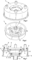
- eine isometrische Darstellung des Anschlussadapters aus der
Figur 1 aus einer ersten Perspektive; - Figur 3
- eine isometrische Darstellung des Anschlussadapters aus der
Figur 1 aus einer zweiten Perspektive; - Figur 4
- den Anschlussadapter aus den
Figuren 1 bis 3 in einem Längsschnitt parallel zu einer Verbindungsachse; - Figur 5
- den Anschlussadapter aus der ersten Perspektive aus der
Figur 2 mit eingesetzten Befestigungsschrauben; - Figur 6
- den Anschlussadapter aus der zweiten Perspektive aus der
Figur 3 mit eingesetzten Befestigungsschrauben; - Figur 7
- den Anschlussadapter in dem Längsschnitt aus der
Figur 4 mit eingesetzten Befestigungsschrauben; - Figur 8
- einen Längsschnitt durch die gesamte Filtervorrichtung aus der
Figur 1 ; - Figur 9
- eine isometrische Darstellung der gesamten Filtervorrichtung aus der
Figur 1 ; - Figur 10
- eine Detailansicht eines Längsschnitts einer Filtervorrichtung für Motoröl einer Brennkraftmaschine, mit einem Anschlusskopf, einem Wechselfilter und einem Anschlussadapter gemäß einem zweiten Ausführungsbeispiel;
- Figur 11
- eine isometrische Darstellung des Anschlussadapters aus der
Figur 10 aus einer ersten Perspektive; - Figur 12
- eine isometrische Darstellung des Anschlussadapters aus der
Figur 10 aus einer zweiten Perspektive; - Figur 13
- den Anschlussadapter aus der
Figur 10 in einem Längsschnitt parallel zu einer Verbindungsachse; - Figur 14
- den Anschlussadapter aus der ersten Perspektive aus der
Figur 11 mit eingesetzten Befestigungsschrauben; - Figur 15
- den Anschlussadapter aus der zweiten Perspektive aus der
Figur 12 mit eingesetzten Befestigungsschrauben; - Figur 16
- den Anschlussadapter in dem Längsschnitt aus der
Figur 13 mit eingesetzten Befestigungsschrauben; - Figur 17
- einen Längsschnitt durch die gesamte Filtervorrichtung aus der
Figur 10 ; - Figur 18
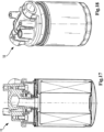
- eine isometrische Darstellung der gesamten Filtervorrichtung aus der
Figur 10 ; - Figur 19
- eine Detailansicht eines Längsschnitts einer Filtervorrichtung für Motoröl einer Brennkraftmaschine, mit einem Anschlusskopf, einem Wechselfilter und einem Anschlussadapter gemäß einem dritten Ausführungsbeispiel;
- Figur 20
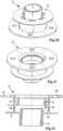
- eine isometrische Darstellung des Anschlussadapters aus der
Figur 19 aus einer ersten Perspektive; - Figur 21
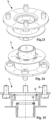
- eine isometrische Darstellung des Anschlussadapters aus der
Figur 19 aus einer zweiten Perspektive; - Figur 22
- den Anschlussadapter aus der
Figur 19 in einem Längsschnitt parallel zu einer Verbindungsachse; - Figur 23
- den Anschlussadapter aus der ersten Perspektive aus der
Figur 20 mit eingesetzten Befestigungsschrauben; - Figur 24
- den Anschlussadapter aus der zweiten Perspektive aus der
Figur 21 mit eingesetzten Befestigungsschrauben; - Figur 25
- den Anschlussadapter in dem Längsschnitt aus der
Figur 22 mit eingesetzten Befestigungsschrauben; - Figur 26
- einen Längsschnitt durch die gesamte Filtervorrichtung aus der
Figur 19 ; - Figur 27
- eine isometrische Darstellung der gesamten Filtervorrichtung aus der
Figur 19 ; - Figur 28
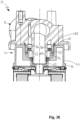
- eine Detailansicht eines Längsschnitts einer alternativen, sich gegenüber der Ausführungsform der
Figur 1 durch die Befestigungsweise unterscheidende Filtervorrichtung, mit einem Anschlusskopf, einem Wechselfilter und einem Anschlussadapter gemäß einem vierten Ausführungsbeispiel zur lösbaren Verbindung des Wechselfilters mit dem Anschlusskopf. - In den Figuren sind gleiche Bauteile mit gleichen Bezugszeichen versehen.
- In den
Figuren 1 bis 9 ist eine Filtervorrichtung 10 in unterschiedlichen Perspektiven, Schnitten und Detailansichten gezeigt. Bei der Filtervorrichtung 10 kann es sich beispielsweise um eine Ölfiltervorrichtung zur Reinigung von Motoröl einer Brennkraftmaschine eines Kraftfahrzeugs handeln. Die Filtervorrichtung 10 kann dabei beispielhaft in einem Motorölkreislauf der Brennkraftmaschine angeordnet sein. - Die Filtervorrichtung 10 umfasst einen Anschlusskopf 12 in der
Figur 1 oben, an den unten über einen Anschlussadapter 14 gemäß einem ersten Ausführungsbeispiel ein Behandlungselement in Form eines Wechselfilters 16 trennbar angeschraubt ist. Die Filtervorrichtung 10 weist eine gedachte Verbindungsachse 18 auf, bezüglich der eine lösbare Schraubverbindung zwischen dem Wechselfilter 16 und dem Anschlussadapter 14 realisiert wird. - Wenn im Folgenden von "radial", "axial", " koaxial", "umfangsmäßig", "exzentrisch" oder dergleichen die Rede ist, so bezieht sich dies, sofern nicht anders erwähnt, auf die Verbindungsachse 18.
- Der Anschlusskopf 12 kann fest mit einem Bauteil der Brennkraftmaschine, beispielsweise einem Motorblock oder einem Rahmen der Brennkraftmaschine, verbunden sein. Der Anschlusskopf 12 umfasst eine Auslassleitung 20 für gereinigtes Öl, welche in einen koaxialen Anschlussstutzen 22 auf der dem Wechselfilter 16 zugewandten Anschlussseite des Anschlusskopfs 12 mündet.
- Die radial äußere Umfangsseite des Anschlussstutzens 22 verläuft konisch und verjüngt sich zu dem freien Ende des Anschlussstutzens 22 hin, welches dem Anschlussadapter 14 zugewandt ist.
- Der Anschlussstutzen 22 ist im Bereich seines dem Wechselfilter 16 axial abgewandten Endes von einer koaxialen Ringwand 24 umgeben. Radial zwischen der Ringwand 24 und dem Anschlussstutzen 22 ist ein Einlassringraum 26 realisiert, in den eine Einlassleitung 28 des Anschlusskopfs 12 für zu reinigendes Motoröl mündet.
- Radial außen ist die Ringwand 24 von einer ringförmigen koaxialen Anschlussfläche 30 umgeben, die dem Anschlussadapter 14 zugewandt ist. In der Anschlussfläche 30 sind umfangsmäßig gleichmäßig verteilt insgesamt 4 Gewindebohrungen 32 angeordnet, deren Achsen parallel zur Verbindungsachse 18 verlaufen.
- Bei dem Wechselfilter 16 handelt es sich um einen an sich bekannten Spin-On-Filter. Der Wechselfilter 16 umfasst ein Filtergehäuse, in dem ein Filterelement zur Reinigung des Motoröls angeordnet ist. Ein Gehäusedeckel 34 verschließt das Filtergehäuse und befindet sich auf der dem Anschlusskopf 12 axial zugewandten Seite.
- Der Gehäusedeckel 34 verfügt über eine koaxiale Verbindungsöffnung 36 mit einem Innengewinde, welche auch als Auslass für gereinigtes Motoröl dient. Die Verbindungsöffnung 36 ist mit einem reinölseitigen Bereich des Innenraums des Filtergehäuses verbunden.
- Die Verbindungsöffnung 36 ist von einer Mehrzahl von exzentrisch angeordneten Einlassöffnungen 38 für zu reinigendes Motoröl umgeben, welche in einen rohölseitigen Bereich des Innenraums des Filtergehäuses führen.
- Im Bereich seines radial äußeren Randes ist an dem Gehäusedeckel 34 eine koaxiale, umfangsmäßig zusammenhängende Ringdichtung 40 angeordnet. Die Ringdichtung 40 dichtet in axialer Richtung gegen den Anschlussadapter 14 ab.
- Der Anschlussadapter 14 ist axial zwischen dem Anschlusskopf 12 und dem Wechselfilter 16 angeordnet. Der Anschlussadapter 14 ist insgesamt einteilig ausgebildet. Der Anschlussadapter 14 hat außen eine etwa becherartige Form. Er verfügt über einen Verbindungsabschnitt 42 zur Verbindung mit dem Anschlusskopf 12 und einen koaxialen Schraubstutzenabschnitt 44 mit einem Außengewinde zum Aufschrauben des Innengewindes der Verbindungsöffnung 36 des Wechselfilters 16.
- Der Anschlussadapter 14 weist eine koaxiale, umfangsmäßig zusammenhängende Umfangswand 46 auf, an die sich auf der dem Anschlusskopf 12 axial zugewandten Bodenseite des becherförmigen Anschlussadapters 14 ein sich umfangsmäßig erstreckender ringförmiger koaxialer Befestigungsabschnitt 48 anschließt. In dem Befestigungsabschnitt 48 sind umfangsmäßig gleichmäßig verteilt beispielhaft vier Schraubenlöcher 50 angeordnet, welche jeweils den Gewindebohrungen 32 des Anschlusskopfs 12 zugeordnet sind. Die Schraubenlöcher 50 sind in radialer Richtung betrachtet jeweils etwa mittig in dem Befestigungsabschnitt 48 angeordnet.
- An einen radial inneren Rand des Befestigungsabschnitts 48 schließt sich ein erster Zylinderabschnitt 52 in Form eines Hohlzylinders an, welcher sich von dem Befestigungsabschnitt 48 weg koaxial ins Innere des becherförmigen Anschlussadapters 14 erstreckt. Der erste Zylinderabschnitt 52 geht einstückig in einen zweiten koaxialen, kopfseitigen Zylinderabschnitt 54 über, welcher ebenfalls die Form eines Hohlzylinders hat. Der Durchmesser des kopfseitigen Zylinderabschnitts 54 ist kleiner als der des ersten Zylinderabschnitts 52. Der kopfseitige Zylinderabschnitt 54 überlappt den ersten Zylinderabschnitt 52 auf der dem Anschlusskopf 12 axial zugewandten Seite. In einer dadurch gebildeten Nut zwischen der radial inneren Umfangsseite des ersten Zylinderabschnitts 52 und der radial äußeren Umfangsseite des kopfseitigen Zylinderabschnitts 54 ist in montiertem Zustand ein Ende der Ringwand 24 des Anschlusskopfs 12 eingesteckt.
- An dem Stirnrand des kopfseitigen Zylinderabschnitts 54, der dem Anschlusskopf 12 zugewandt ist, ist eine rohölseitige koaxiale Ringdichtung 56 angeordnet, welche den kopfseitigen Zylinderabschnitt 54 gegen den ersten Zylinderabschnitt 52 rohölseitig auf Seiten des Einlassringraums 26 abdichtet und Teil einer Kopf-Dichteinrichtung ist.
- An seinem axial gegenüberliegenden Rand, der dem Wechselfilter 16 zugewandt ist, geht der kopfseitige Zylinderabschnitt 54 über einen sich nach radial innen erstreckenden Kragen 58 in einen dritten koaxialen, elementseitigen Zylinderabschnitt 60 ebenfalls in Form eines Hohlzylinders über. Der Durchmesser des elementseitigen Zylinderabschnitts 60 ist kleiner als der Durchmesser des kopfseitigen Zylinderabschnitts 54.
- In dem Kragen 58 sind umfangsmäßig verteilt mehrere Öldurchlasslöcher 62 angeordnet. Mit den Öldurchlasslöchern 62 wird ein ölführender Ringraum 64 mit einem Öleinlassraum 66 verbunden. Der Ringraum 64 ist radial zwischen der radial inneren Umfangsseite des kopfseitigen Zylinderabschnitts 54 und einer radial äußeren Umfangsseite des Anschlussstutzens 22 angeordnet. Der Öleinlassraum 66 ist von dem Befestigungsabschnitt 48, den Zylinderabschnitten 52, 54 und 60, der Umfangswand 46 und in montiertem Zustand von dem Gehäusedeckel 34 des Wechselfilters 16 begrenzt.
- Auf der den Öldurchlasslöchern 62 axial gegenüberliegenden Seite bildet eine Lücke zwischen der radial äußeren Umfangswand des Anschlussstutzens 22 und der rohölseitigen Ringdichtung 56 eine Ölverbindung zwischen dem Einlassringraum 26 des Anschlusskopfes 12 und dem Ringraum 64 im Bereich des Anschlussadapters 14.
- Der Ringraum 64, die Öldurchlasslöcher 62 und der Öleinlassraum 66 bilden eine bezüglich dem Schraubstutzenabschnitt 44 radial außen gelegene Ölleitung für zu reinigendes Motoröl zur Verbindung des Einlassringraums 26 auf Seiten des Anschlusskopfs 12 mit den Einlassöffnungen 38 aufseiten des Wechselfilters 16.
- An dem Rand des elementseitigen Zylinderabschnitts 60, der dem Anschlusskopf 12 axial zugewandt ist, ist eine koaxiale umfangsmäßig zusammenhängende reinölseitige Ringdichtung 68 angeordnet. Die reinölseitige Ringdichtung 68 dichtet die radial äußere Umfangsseite des Anschlussstutzens 22 gegen den elementseitigen Zylinderabschnitt 60 ab und trennt den rohölseitigen Ringraum 64 von den reinölseitigen Innenräumen des Schraubstutzenabschnitts 44 und des Anschlussstutzens 22. Die Ringdichtung 68 ist Teil einer Element-Dichteinrichtung.
- Auf der Seite, die der reinölseitigen Ringdichtung 68 axial abgewandt ist, geht der elementseitige Zylinderabschnitt 60 über eine sich nach radial innen erstreckende Stufe in den querschnittsverjüngten Schraubstutzenabschnitt 44 über.
- Bei montiertem Wechselfilter 16 liegt die freie Stirnseite des Anschlussstutzens 22 an der Stufe am Übergang zwischen dem elementseitigen Zylinderabschnitt 60 und dem Schraubstutzenabschnitt 44 an. Der Innenraum des Schraubstutzenabschnitts 44 bildet einen Öldurchlasskanal zur Verbindung des reinölseitigen Innenraums des Wechselfilters 16 mit der Auslassleitung 20.
- Zur Fixierung des Anschlussadapters 14 sind beispielhaft vier Befestigungsschrauben 70 vorgesehen, welche von der dem Wechselfilter 16 zugewandten Seite durch die Schraubenlöcher 50 führen und in den Gewindebohrungen 32 verschraubt sind.
- Zwischen den Köpfen der Befestigungsschrauben 70 und dem Befestigungsabschnitt 48 ist jeweils eine Ringdichtung, beispielhaft in Form von O-Ringdichtungen 72, angeordnet. Die O-Ringdichtungen 72 liegen jeweils dichtend an entsprechenden ringförmigen, die jeweiligen Schraubenlöcher 50 jeweils umgebenden Dichtflächen 74 an. Die O-Ringdichtungen 72 dichten den rohölseitigen Öleinlassraum 66 im Bereich der Befestigungsschrauben 70 gegen die Umgebung ab. Jeweils eine O-Ringdichtung 72 bildet mit der entsprechenden Dichtfläche 74 eine Schraubenloch-Dichteinrichtung.
- Der dem Wechselfilter 16 zugewandte freie Rand der Umfangswand 46 weist einen Dichtkragen 76 auf, der sich bevorzugt nach radial außen erstreckt, um eine gegenüber der Dicke der Umfangswand 46 breitere Dichtfläche zur Verfügung zu stellen. Der Dichtkragen 76 liegt dichtend an der Ringdichtung 40 des Wechselfilters 16 an.
- In den
Figuren 10 bis 18 ist eine Filtervorrichtung 10 mit einem Anschlussadapter 14 gemäß einem zweiten Ausführungsbeispiel gezeigt. Diejenigen Elemente, die zu denen des ersten Ausführungsbeispiels aus denFiguren 1 bis 9 ähnlich sind, sind mit denselben Bezugszeichen versehen. Das zweite Ausführungsbeispiel unterscheidet sich von dem ersten Ausführungsbeispiel dadurch, dass die Schraubenlöcher 50 statt mittig in dem Befestigungsabschnitt 48 angeordnet zu dem ersten Zylinderabschnitt 52 nach radial innen versetzt sind. - In den
Figuren 19 bis 27 ist eine Filtervorrichtung 10 mit einem Anschlussadapter 14 gemäß einem dritten Ausführungsbeispiel gezeigt. Diejenigen Elemente, die zu denen des ersten Ausführungsbeispiels aus denFiguren 1 bis 10 ähnlich sind, sind mit denselben Bezugszeichen versehen. Das dritte Ausführungsbeispiel unterscheidet sich von dem ersten Ausführungsbeispiel dadurch, dass die Umfangswand 46 nach radial innen versetzt ist, so dass sich die Schraubenlöcher 50 radial außerhalb der Umfangswand 46 befinden. Außerdem geht die Umfangswand 46 direkt in den ersten Zylinderabschnitt 52 über. Die Umfangswand 46 ist mit ihrem dem Wechselfilter 16 axial zugewandten Rand über eine ringscheibenförmige Verbindung, welche die Öldurchlasslöcher 62 und die Dichtfläche 74 aufweist, mit dem elementseitigen Zylinderabschnitt 60 verbunden. Der elementseitige Zylinderabschnitt 60 geht seinerseits mit gleichem Durchmesser direkt in den Anschlussstutzen 22 über. - In der
Figur 28 ist eine Filtervorrichtung 10 mit einem Anschlussadapter 14 gemäß einem vierten Ausführungsbeispiel gezeigt, welches sich gegenüber der Ausführungsform derFiguren 1 bis 9 durch die Befestigungsweise des Anschlussadapters 14 am Anschlusskopf 12 unterscheidet. Hierzu ist statt der Schrauben 70 ein Zentralgewinde 480 zwischen Anschlusskopf 12 und Anschlussadapter 14 vorgesehen. Dies hat den Vorteil, dass keine Schraubenlöcher 50 (sieheFig. 1 ) vorgesehen sein müssen. Das Zentralgewinde 480 ist bevorzugt wie gezeigt radial außerhalb der Dichtungen, insbesondere außerhalb der Kopf-Dichteinrichtung 56 und der reinölseitigen Ringdichtung 68, und damit außerhalb des von Fluiden durchströmten oder berührten Bereichs angeordnet. Bevorzugt weist, wie inFigur 28 gezeigt, der erste Zylinderabschnitt 52 ein Innengewinde und die Ringwand 24 ein Außengewinde auf zur Bildung des Zentralgewindes 480. Somit weist der alternative Anschlussadapter 14 eine koaxiale, umfangsmäßig zusammenhängende Umfangswand 46, abweichend von der Ausführungsform derFigur 1 eine geschlossene, dem Anschlusskopf 12 axial zugewandte Bodenseite des becherförmigen Anschlussadapters 14 sowie einen an die Bodenseite anschließenden Befestigungsabschnitt 48, der durch das Zentralgewinde 480 gebildet ist, auf. Das Zentralgewinde 480 ist koaxial zu den Dichtungen 68, 56. Das Zentralgewinde 480 ist bevorzugt axial relativ zu den Dichtungen 68, 56 so angeordnet, dass diese erst in dichtende Position gelangen, wenn ein Teil des Gewindewegs des Innengewindes bei dessen Montage überwunden ist. So kann eine gute Zentrierung und die Gefahr des Verkantens oder von Beschädigungen der Dichtungen 68, 56 bei der Montage verhindert werden. Es sei verstanden, dass eine analoge Modifikation auch für die in denFiguren 10 - 18 und19 - 27 gezeigten Ausführungsformen möglich und erfindungsgemäß ist, wobei jeweils der erste Zylinderabschnitt 52 ein Innengewinde als Zentralgewinde 480 aufweist. In allen Varianten ist das Zentralgewinde bevorzugt radial gesehen außerhalb der Dichtungen 56, 68 angeordnet, anders ausgedrückt weist das Zentralgewinde 480 bevorzugt einen größeren Durchmesser auf als die Dichtungen 56, 68 und/oder deren Dichtflächen.
Claims (12)
- Anschlussadapter (14) zum Anschluss einer Behandlungseinrichtung (16) an einen Anschlusskopf (12) einer Behandlungsvorrichtung (10) für insbesondere flüssige Fluide, insbesondere einer Brennkraftmaschine, insbesondere eines Kraftfahrzeugs, wobei der Anschlussadapter (14) einen Verbindungsabschnitt (42) zur Verbindung mit dem Anschlusskopf (12) und einen zu einer gedachten Verbindungsachse (18) koaxialen Schraubstutzenabschnitt (44) aufweist zum Anschrauben der Behandlungseinrichtung (16), wobei der Schraubstutzenabschnitt (44) wenigstens einen Fluiddurchlasskanal zur Verbindung eines fluidführenden Raumes der Behandlungseinrichtung (16) mit einem fluidführenden Raum (20) des Anschlusskopfs (12) umfasst, wobei der wenigstens eine Verbindungsabschnitt (42) wenigstens zwei Schraubenlöcher (50) für Schrauben (70) oder Gewindebolzen oder ein Zentralgewinde (480) zur Verbindung mit einem anschlusskopfseitigen Zentralgewinde aufweist, dadurch gekennzeichnet, dass die Behandlungseinrichtung einen Wechselfilter (16) aufweist und der Anschlussadapter (14) einen dem anzuschließenden Wechselfilter (16) zugewandten Dichtkragen (76) zur Anlage einer äußeren Ringdichtung (40) des anzuschließenden Wechselfilters (16) aufweist, der bevorzugt an einem freien Rand der Umfangswand (46) angeordnet ist, wobei der Dichtkragen (76) radial außerhalb des Verbindungsabschnitts (42) angeordnet ist.
- Anschlussadapter nach Anspruch 1, dadurch gekennzeichnet, dass die Schraubenlöcher (50) bezüglich der Verbindungsachse (18) radial außerhalb des Schraubstutzenabschnitts (44) oder einer axialen Projektion des Schraubstutzenabschnitts (44) angeordnet sind.
- Anschlussadapter nach Anspruch 1 oder 2, dadurch gekennzeichnet, dass der Anschlussadapter (14) wenigstens einen Teil (64, 66) wenigstens einer radial außen gelegenen Fluidleitung aufweist, die sich radial außerhalb des Schraubstutzenabschnitts (44) oder einer axialen Projektion des Schraubstutzenabschnitts (44) befindet und die zur Verbindung eines weiteren fluidführenden Raumes der Behandlungseinrichtung (16) mit einem weiteren fluidführenden Raum (26) des Anschlusskopfs (12) dient.
- Anschlussadapter nach einem der vorigen Ansprüche, dadurch gekennzeichnet, dass der Verbindungsabschnitt (42) wenigstens einen zur Verbindungsachse (18) koaxialen Zylinderabschnitt (54, 60) zur Aufnahme eines zur Verbindungsachse (18) koaxialen Anschlussstutzens (22) des Anschlusskopfs (12) aufweist.
- Anschlussadapter nach einem der vorigen Ansprüche, dadurch gekennzeichnet, dass der Anschlussadapter (14) eine Umfangswand (46) aufweist, welche wenigstens einen fluidleitenden Ringraum (66) des Anschlussadapters (14) bezüglich der Verbindungsachse (18) umfangsmäßig umgibt.
- Anschlussadapter nach einem der vorigen Ansprüche, dadurch gekennzeichnet, dass der Dichtkragen (76) radial außerhalb der wenigstens zwei Schraubenlöcher (50) oder des Zentralgewindes (480) angeordnet ist.
- Anschlussadapter nach Anspruch 5 oder 6, dadurch gekennzeichnet, dass wenigstens ein Schraubenloch (50) bezüglich der Verbindungsachse (18) radial innerhalb der Umfangswand (46) oder einer axialen Projektion der Umfangswand (46) angeordnet ist und/oder wenigstens ein Schraubenloch (50) bezüglich der Verbindungsachse (18) radial außerhalb der Umfangswand (46) oder einer axialen Projektion der Umfangswand (46) angeordnet ist.
- Anschlussadapter nach einem der vorigen Ansprüche, dadurch gekennzeichnet, dass der Anschlussadapter (14) wenigstens einen Teil einer Element-Dichteinrichtung (68) zum Abdichten einer Verbindung zu der Behandlungseinrichtung (16) und/oder wenigstens einen Teil einer Kopf-Dichteinrichtung (56) zum Abdichten einer Verbindung zu dem Anschlusskopf (12) aufweist.
- Anschlussadapter nach einem der vorigen Ansprüche, dadurch gekennzeichnet, dass wenigstens an einem Schraubenloch (50) wenigstens ein Teil einer Schraubenloch-Dichteinrichtung (72, 74) angeordnet ist.
- Anschlussadapter nach einem der vorigen Ansprüche, dadurch gekennzeichnet, dass der Anschlussadapter (14) mit dem Verbindungsabschnitt (42) und dem Schraubstutzenabschnitt (44) einteilig ausgestaltet ist.
- Vorrichtung umfassend einen Anschlusskopf (12) einer Behandlungsvorrichtung (10) für insbesondere flüssige Fluide und wenigstens einem Anschlussadapter (14) nach einem der vorhergehenden Ansprüche, wobei der Verbindungsabschnitt (42) des wenigstens einen Anschlussadapters (14) mit dem Anschlusskopf (12) verbunden ist und wobei der Anschlusskopf (12) einen fluidführenden Raum (20) aufweist und der Fluiddurchlasskanal des Schraubstutzenabschnitts (44) ausgebildet ist zur Verbindung eines fluidführenden Raumes der Behandlungseinrichtung (16) mit dem fluidführenden Raum (20) des Anschlusskopfs (12).
- Behandlungsvorrichtung (10) umfassend wenigstens eine Vorrichtung nach Anspruch 11 und wenigstens eine Behandlungseinrichtung (16), wobei mit dem wenigstens einen Anschlussadapter (14) die Behandlungseinrichtung (16) an den wenigstens einen Anschlusskopf (12) angeschlossen ist, wobei der wenigstens eine Fluiddurchlasskanal des Schraubstutzenabschnitts (44) einen fluidführenden Raumes der wenigstens einen Behandlungseinrichtung (16) mit dem fluidführenden Raum (20) des Anschlusskopfs (12) verbindet und wobei die Behandlungseinrichtung einen Wechselfilter (16) aufweist.
Applications Claiming Priority (2)
| Application Number | Priority Date | Filing Date | Title |
|---|---|---|---|
| DE102017003368 | 2017-04-06 | ||
| PCT/EP2018/058873 WO2018185292A1 (de) | 2017-04-06 | 2018-04-06 | Anschlussadapter zum anschluss einer behandlungseinrichtung an einen anschlusskopf einer behandlungsvorrichtung für insbesondere flüssige fluide, anschlusskopf und behandlungsvorrichtung |
Publications (2)
| Publication Number | Publication Date |
|---|---|
| EP3607176A1 EP3607176A1 (de) | 2020-02-12 |
| EP3607176B1 true EP3607176B1 (de) | 2023-07-12 |
Family
ID=62002116
Family Applications (1)
| Application Number | Title | Priority Date | Filing Date |
|---|---|---|---|
| EP18718119.3A Active EP3607176B1 (de) | 2017-04-06 | 2018-04-06 | Anschlussadapter zum anschluss einer behandlungseinrichtung an einen anschlusskopf einer behandlungsvorrichtung für insbesondere flüssige fluide, anschlusskopf und behandlungsvorrichtung |
Country Status (7)
| Country | Link |
|---|---|
| US (1) | US11365657B2 (de) |
| EP (1) | EP3607176B1 (de) |
| CN (1) | CN110462175B (de) |
| DE (2) | DE102018002909A1 (de) |
| ES (1) | ES2952983T3 (de) |
| PL (1) | PL3607176T3 (de) |
| WO (1) | WO2018185292A1 (de) |
Families Citing this family (1)
| Publication number | Priority date | Publication date | Assignee | Title |
|---|---|---|---|---|
| USD958931S1 (en) * | 2020-08-26 | 2022-07-26 | Wuhu TianHao E-commerce CO., LTD. | Oil water separator with replaceable filter |
Family Cites Families (23)
| Publication number | Priority date | Publication date | Assignee | Title |
|---|---|---|---|---|
| US3334754A (en) * | 1964-11-23 | 1967-08-08 | Marvel Eng Co | Filter head structure |
| US4492632A (en) * | 1983-12-16 | 1985-01-08 | Mattson Fred P | Adaptor for external oil filter |
| DE4037628A1 (de) * | 1990-11-27 | 1992-06-04 | Reinhard Weber | Zwischenplatte zwischen spin-on-filter und motorblock |
| US5291969A (en) * | 1992-06-16 | 1994-03-08 | Diederich Paul W Jun | Adapter mechanism for fluid cooling and filtering |
| US5743358A (en) * | 1993-09-22 | 1998-04-28 | K. J. Manufacturing Co. | Filter mounting adapter and fitting mounted to same |
| US5484527A (en) * | 1993-12-13 | 1996-01-16 | Stanadyne Automotive Corp. | Module for filter assembly base |
| EP0658362B1 (de) * | 1993-12-13 | 1998-11-25 | Stanadyne Automotive Corp. | Hauptfiltrationsmodul für Brennstoff mit wahlweisen Umstellmöglichkeiten |
| US5762671A (en) | 1997-02-13 | 1998-06-09 | Farrow; James V. | Multi-size threaded adapter |
| US20010037971A1 (en) * | 1999-05-28 | 2001-11-08 | Gary P. Bergeron | Oil filter adapter |
| US6355169B1 (en) * | 2000-04-24 | 2002-03-12 | Vortex International, Llc | Oil filter adapter ring |
| JP4159284B2 (ja) * | 2001-12-21 | 2008-10-01 | 富士重工業株式会社 | オイルフィルタ装置 |
| US7329337B2 (en) * | 2003-05-22 | 2008-02-12 | Caterpillar Inc. | Universal filter base and engines using same |
| US20070267339A1 (en) * | 2004-04-21 | 2007-11-22 | Munn Myron L | Oil filter adapter |
| DE102004059061B4 (de) | 2004-12-07 | 2021-12-02 | Mann+Hummel Gmbh | Flüssigkeitsfilter und Verwendung desselben |
| CN1840871A (zh) * | 2005-03-11 | 2006-10-04 | 卡特彼勒公司 | 可安装在远处的过滤器组件 |
| US20120285876A1 (en) * | 2011-05-10 | 2012-11-15 | Parker-Hannifin Corporation | Filter manifold mount |
| FR2976188A1 (fr) * | 2011-06-09 | 2012-12-14 | Filtrauto | Filtre a liquide et sous-ensemble de moteur formant support de montage pour une cartouche filtrante |
| US9011566B2 (en) | 2012-11-29 | 2015-04-21 | Filterspec Inc. | Filter cartridge apparatus |
| FI124391B (en) * | 2013-01-10 | 2014-08-15 | Outotec Finland Oy | Filter plate connector |
| GB201315647D0 (en) | 2013-09-03 | 2013-10-16 | Parker Hannifin Mfg Ltd | A filter element and cover assembly therefor |
| US20150298033A1 (en) * | 2014-04-21 | 2015-10-22 | Hatton Marine and Industrial Repair, Inc. | Fuel filter adapter plate |
| BR102014020222A2 (pt) | 2014-08-14 | 2015-06-09 | Devocir Antônio Lira | Conector universal para filtro de combustível para máquinas agrícolas |
| CN205689262U (zh) * | 2016-06-03 | 2016-11-16 | 力帆实业(集团)股份有限公司 | 摩托车发动机机油滤清器 |
-
2018
- 2018-04-06 WO PCT/EP2018/058873 patent/WO2018185292A1/de not_active Ceased
- 2018-04-06 PL PL18718119.3T patent/PL3607176T3/pl unknown
- 2018-04-06 ES ES18718119T patent/ES2952983T3/es active Active
- 2018-04-06 DE DE102018002909.4A patent/DE102018002909A1/de not_active Withdrawn
- 2018-04-06 DE DE112018001917.9T patent/DE112018001917A5/de not_active Withdrawn
- 2018-04-06 EP EP18718119.3A patent/EP3607176B1/de active Active
- 2018-04-06 CN CN201880021562.0A patent/CN110462175B/zh active Active
-
2019
- 2019-10-04 US US16/593,805 patent/US11365657B2/en active Active
Also Published As
| Publication number | Publication date |
|---|---|
| CN110462175A (zh) | 2019-11-15 |
| CN110462175B (zh) | 2022-07-12 |
| ES2952983T3 (es) | 2023-11-07 |
| US20200102921A1 (en) | 2020-04-02 |
| US11365657B2 (en) | 2022-06-21 |
| EP3607176A1 (de) | 2020-02-12 |
| PL3607176T3 (pl) | 2023-11-27 |
| WO2018185292A1 (de) | 2018-10-11 |
| DE102018002909A1 (de) | 2018-10-11 |
| DE112018001917A5 (de) | 2019-12-19 |
Similar Documents
| Publication | Publication Date | Title |
|---|---|---|
| EP2982427B1 (de) | Gehäuse und einrichtung zur abscheidung eines fluids | |
| EP2459295B1 (de) | Filter | |
| EP3228374B1 (de) | Wechselfilter einer behandlungsvorrichtung zur behandlung von insbesondere flüssigen fluiden und behandlungsvorrichtung | |
| EP3096859B1 (de) | Filterelement | |
| EP3408009B1 (de) | Gehäuse, fluidauslass-dichtungsteil, gehäusedeckel und verbindungsteil einer einrichtung zur abscheidung wenigstens eines fluids aus gas und einrichtung und vorrichtung zur abscheidung eines fluids | |
| EP3473322A1 (de) | Becherförmiges gehäuse, vorrichtung zum abscheiden von flüssigkeit aus luft sowie verfahren zur montage des becherförmigen gehäuses auf einen nippel | |
| EP3019265B1 (de) | Spin-on filter für eine filtervorrichtung für fluid und filtervorrichtung | |
| DE102012209242A1 (de) | Filtereinrichtung | |
| DE102015008328B4 (de) | Filteranschlusseinrichtung und Filtereinrichtung | |
| EP3727643B1 (de) | Filterelement eines filters für flüssigkeit und filter | |
| EP3607176B1 (de) | Anschlussadapter zum anschluss einer behandlungseinrichtung an einen anschlusskopf einer behandlungsvorrichtung für insbesondere flüssige fluide, anschlusskopf und behandlungsvorrichtung | |
| DE102016010523B4 (de) | Filtergehäuse eines austauschbaren Filters, Filter und Filtervorrichtung | |
| EP3793707B1 (de) | Filter mit einem filtergehäuse und einem zwischendeckel | |
| DE102016008732A1 (de) | Fluidgehäuse eines Fluidbehandlungssystem und Fluidbehandlungssystem | |
| WO2022053384A1 (de) | Filterelement, filtereinrichtung, anordnung und montageverfahren | |
| EP3727642B1 (de) | Filter mit einem ablassverschlusselement | |
| DE102015008694A1 (de) | Hohlfilterelement eines Flüssigkeitsfilters, Flüssigkeitsfilter, Filtersystem und Adapterelement eines Hohlfilterelements | |
| EP2114546B1 (de) | Filterelement zur abreinigung von fluiden | |
| EP2108429A1 (de) | Filterverschluss-System | |
| EP4028143B1 (de) | Fluid-reinigungselement eines fluid-reinigungssystems zum reinigen von flüssigem fluid, fluid-reinigungssystem und dichtelement eines fluid-reinigungselements | |
| DE102014005348B4 (de) | Filterelement eines Filters und Filter | |
| DE102017004558B4 (de) | Gehäusemodul eines Fluidbehandlungsmoduls und Fluidbehandlungsmodul | |
| EP4620552A1 (de) | Filterelement, ionentauscher-filterelement und filtersystem | |
| WO2017153210A1 (de) | Filteranschlussvorrichtung einer filtervorrichtung zum anschluss eines austauschbaren filters und filtervorrichtung | |
| WO2025011836A1 (de) | Filterelement, ablassverschlusselement und filtersystem |
Legal Events
| Date | Code | Title | Description |
|---|---|---|---|
| STAA | Information on the status of an ep patent application or granted ep patent |
Free format text: STATUS: UNKNOWN |
|
| STAA | Information on the status of an ep patent application or granted ep patent |
Free format text: STATUS: THE INTERNATIONAL PUBLICATION HAS BEEN MADE |
|
| PUAI | Public reference made under article 153(3) epc to a published international application that has entered the european phase |
Free format text: ORIGINAL CODE: 0009012 |
|
| STAA | Information on the status of an ep patent application or granted ep patent |
Free format text: STATUS: REQUEST FOR EXAMINATION WAS MADE |
|
| 17P | Request for examination filed |
Effective date: 20190926 |
|
| AK | Designated contracting states |
Kind code of ref document: A1 Designated state(s): AL AT BE BG CH CY CZ DE DK EE ES FI FR GB GR HR HU IE IS IT LI LT LU LV MC MK MT NL NO PL PT RO RS SE SI SK SM TR |
|
| AX | Request for extension of the european patent |
Extension state: BA ME |
|
| DAV | Request for validation of the european patent (deleted) | ||
| DAX | Request for extension of the european patent (deleted) | ||
| RAP3 | Party data changed (applicant data changed or rights of an application transferred) |
Owner name: MANN+HUMMEL GMBH |
|
| STAA | Information on the status of an ep patent application or granted ep patent |
Free format text: STATUS: EXAMINATION IS IN PROGRESS |
|
| 17Q | First examination report despatched |
Effective date: 20210601 |
|
| GRAP | Despatch of communication of intention to grant a patent |
Free format text: ORIGINAL CODE: EPIDOSNIGR1 |
|
| STAA | Information on the status of an ep patent application or granted ep patent |
Free format text: STATUS: GRANT OF PATENT IS INTENDED |
|
| INTG | Intention to grant announced |
Effective date: 20230208 |
|
| GRAS | Grant fee paid |
Free format text: ORIGINAL CODE: EPIDOSNIGR3 |
|
| GRAA | (expected) grant |
Free format text: ORIGINAL CODE: 0009210 |
|
| STAA | Information on the status of an ep patent application or granted ep patent |
Free format text: STATUS: THE PATENT HAS BEEN GRANTED |
|
| AK | Designated contracting states |
Kind code of ref document: B1 Designated state(s): AL AT BE BG CH CY CZ DE DK EE ES FI FR GB GR HR HU IE IS IT LI LT LU LV MC MK MT NL NO PL PT RO RS SE SI SK SM TR |
|
| REG | Reference to a national code |
Ref country code: CH Ref legal event code: EP |
|
| REG | Reference to a national code |
Ref country code: DE Ref legal event code: R096 Ref document number: 502018012673 Country of ref document: DE |
|
| REG | Reference to a national code |
Ref country code: IE Ref legal event code: FG4D Free format text: LANGUAGE OF EP DOCUMENT: GERMAN |
|
| REG | Reference to a national code |
Ref country code: LT Ref legal event code: MG9D |
|
| REG | Reference to a national code |
Ref country code: NL Ref legal event code: MP Effective date: 20230712 |
|
| PG25 | Lapsed in a contracting state [announced via postgrant information from national office to epo] |
Ref country code: NL Free format text: LAPSE BECAUSE OF FAILURE TO SUBMIT A TRANSLATION OF THE DESCRIPTION OR TO PAY THE FEE WITHIN THE PRESCRIBED TIME-LIMIT Effective date: 20230712 |
|
| PG25 | Lapsed in a contracting state [announced via postgrant information from national office to epo] |
Ref country code: GR Free format text: LAPSE BECAUSE OF FAILURE TO SUBMIT A TRANSLATION OF THE DESCRIPTION OR TO PAY THE FEE WITHIN THE PRESCRIBED TIME-LIMIT Effective date: 20231013 |
|
| PG25 | Lapsed in a contracting state [announced via postgrant information from national office to epo] |
Ref country code: IS Free format text: LAPSE BECAUSE OF FAILURE TO SUBMIT A TRANSLATION OF THE DESCRIPTION OR TO PAY THE FEE WITHIN THE PRESCRIBED TIME-LIMIT Effective date: 20231112 |
|
| PG25 | Lapsed in a contracting state [announced via postgrant information from national office to epo] |
Ref country code: SE Free format text: LAPSE BECAUSE OF FAILURE TO SUBMIT A TRANSLATION OF THE DESCRIPTION OR TO PAY THE FEE WITHIN THE PRESCRIBED TIME-LIMIT Effective date: 20230712 Ref country code: RS Free format text: LAPSE BECAUSE OF FAILURE TO SUBMIT A TRANSLATION OF THE DESCRIPTION OR TO PAY THE FEE WITHIN THE PRESCRIBED TIME-LIMIT Effective date: 20230712 Ref country code: PT Free format text: LAPSE BECAUSE OF FAILURE TO SUBMIT A TRANSLATION OF THE DESCRIPTION OR TO PAY THE FEE WITHIN THE PRESCRIBED TIME-LIMIT Effective date: 20231113 Ref country code: NO Free format text: LAPSE BECAUSE OF FAILURE TO SUBMIT A TRANSLATION OF THE DESCRIPTION OR TO PAY THE FEE WITHIN THE PRESCRIBED TIME-LIMIT Effective date: 20231012 Ref country code: LV Free format text: LAPSE BECAUSE OF FAILURE TO SUBMIT A TRANSLATION OF THE DESCRIPTION OR TO PAY THE FEE WITHIN THE PRESCRIBED TIME-LIMIT Effective date: 20230712 Ref country code: LT Free format text: LAPSE BECAUSE OF FAILURE TO SUBMIT A TRANSLATION OF THE DESCRIPTION OR TO PAY THE FEE WITHIN THE PRESCRIBED TIME-LIMIT Effective date: 20230712 Ref country code: IS Free format text: LAPSE BECAUSE OF FAILURE TO SUBMIT A TRANSLATION OF THE DESCRIPTION OR TO PAY THE FEE WITHIN THE PRESCRIBED TIME-LIMIT Effective date: 20231112 Ref country code: HR Free format text: LAPSE BECAUSE OF FAILURE TO SUBMIT A TRANSLATION OF THE DESCRIPTION OR TO PAY THE FEE WITHIN THE PRESCRIBED TIME-LIMIT Effective date: 20230712 Ref country code: GR Free format text: LAPSE BECAUSE OF FAILURE TO SUBMIT A TRANSLATION OF THE DESCRIPTION OR TO PAY THE FEE WITHIN THE PRESCRIBED TIME-LIMIT Effective date: 20231013 Ref country code: FI Free format text: LAPSE BECAUSE OF FAILURE TO SUBMIT A TRANSLATION OF THE DESCRIPTION OR TO PAY THE FEE WITHIN THE PRESCRIBED TIME-LIMIT Effective date: 20230712 |
|
| REG | Reference to a national code |
Ref country code: DE Ref legal event code: R097 Ref document number: 502018012673 Country of ref document: DE |
|
| PG25 | Lapsed in a contracting state [announced via postgrant information from national office to epo] |
Ref country code: SM Free format text: LAPSE BECAUSE OF FAILURE TO SUBMIT A TRANSLATION OF THE DESCRIPTION OR TO PAY THE FEE WITHIN THE PRESCRIBED TIME-LIMIT Effective date: 20230712 Ref country code: RO Free format text: LAPSE BECAUSE OF FAILURE TO SUBMIT A TRANSLATION OF THE DESCRIPTION OR TO PAY THE FEE WITHIN THE PRESCRIBED TIME-LIMIT Effective date: 20230712 Ref country code: EE Free format text: LAPSE BECAUSE OF FAILURE TO SUBMIT A TRANSLATION OF THE DESCRIPTION OR TO PAY THE FEE WITHIN THE PRESCRIBED TIME-LIMIT Effective date: 20230712 Ref country code: DK Free format text: LAPSE BECAUSE OF FAILURE TO SUBMIT A TRANSLATION OF THE DESCRIPTION OR TO PAY THE FEE WITHIN THE PRESCRIBED TIME-LIMIT Effective date: 20230712 Ref country code: CZ Free format text: LAPSE BECAUSE OF FAILURE TO SUBMIT A TRANSLATION OF THE DESCRIPTION OR TO PAY THE FEE WITHIN THE PRESCRIBED TIME-LIMIT Effective date: 20230712 Ref country code: SK Free format text: LAPSE BECAUSE OF FAILURE TO SUBMIT A TRANSLATION OF THE DESCRIPTION OR TO PAY THE FEE WITHIN THE PRESCRIBED TIME-LIMIT Effective date: 20230712 |
|
| P01 | Opt-out of the competence of the unified patent court (upc) registered |
Effective date: 20240321 |
|
| PLBE | No opposition filed within time limit |
Free format text: ORIGINAL CODE: 0009261 |
|
| STAA | Information on the status of an ep patent application or granted ep patent |
Free format text: STATUS: NO OPPOSITION FILED WITHIN TIME LIMIT |
|
| 26N | No opposition filed |
Effective date: 20240415 |
|
| PG25 | Lapsed in a contracting state [announced via postgrant information from national office to epo] |
Ref country code: SI Free format text: LAPSE BECAUSE OF FAILURE TO SUBMIT A TRANSLATION OF THE DESCRIPTION OR TO PAY THE FEE WITHIN THE PRESCRIBED TIME-LIMIT Effective date: 20230712 |
|
| PG25 | Lapsed in a contracting state [announced via postgrant information from national office to epo] |
Ref country code: MC Free format text: LAPSE BECAUSE OF FAILURE TO SUBMIT A TRANSLATION OF THE DESCRIPTION OR TO PAY THE FEE WITHIN THE PRESCRIBED TIME-LIMIT Effective date: 20230712 |
|
| PG25 | Lapsed in a contracting state [announced via postgrant information from national office to epo] |
Ref country code: MC Free format text: LAPSE BECAUSE OF FAILURE TO SUBMIT A TRANSLATION OF THE DESCRIPTION OR TO PAY THE FEE WITHIN THE PRESCRIBED TIME-LIMIT Effective date: 20230712 |
|
| REG | Reference to a national code |
Ref country code: CH Ref legal event code: PL |
|
| PG25 | Lapsed in a contracting state [announced via postgrant information from national office to epo] |
Ref country code: LU Free format text: LAPSE BECAUSE OF NON-PAYMENT OF DUE FEES Effective date: 20240406 |
|
| REG | Reference to a national code |
Ref country code: BE Ref legal event code: MM Effective date: 20240430 |
|
| PG25 | Lapsed in a contracting state [announced via postgrant information from national office to epo] |
Ref country code: LU Free format text: LAPSE BECAUSE OF NON-PAYMENT OF DUE FEES Effective date: 20240406 |
|
| PG25 | Lapsed in a contracting state [announced via postgrant information from national office to epo] |
Ref country code: BE Free format text: LAPSE BECAUSE OF NON-PAYMENT OF DUE FEES Effective date: 20240430 |
|
| PG25 | Lapsed in a contracting state [announced via postgrant information from national office to epo] |
Ref country code: BE Free format text: LAPSE BECAUSE OF NON-PAYMENT OF DUE FEES Effective date: 20240430 Ref country code: CH Free format text: LAPSE BECAUSE OF NON-PAYMENT OF DUE FEES Effective date: 20240430 |
|
| PG25 | Lapsed in a contracting state [announced via postgrant information from national office to epo] |
Ref country code: IE Free format text: LAPSE BECAUSE OF NON-PAYMENT OF DUE FEES Effective date: 20240406 |
|
| REG | Reference to a national code |
Ref country code: AT Ref legal event code: MM01 Ref document number: 1587393 Country of ref document: AT Kind code of ref document: T Effective date: 20240406 |
|
| PGFP | Annual fee paid to national office [announced via postgrant information from national office to epo] |
Ref country code: DE Payment date: 20250422 Year of fee payment: 8 |
|
| PGFP | Annual fee paid to national office [announced via postgrant information from national office to epo] |
Ref country code: GB Payment date: 20250423 Year of fee payment: 8 Ref country code: ES Payment date: 20250530 Year of fee payment: 8 |
|
| PGFP | Annual fee paid to national office [announced via postgrant information from national office to epo] |
Ref country code: IT Payment date: 20250424 Year of fee payment: 8 |
|
| PGFP | Annual fee paid to national office [announced via postgrant information from national office to epo] |
Ref country code: FR Payment date: 20250425 Year of fee payment: 8 |
|
| PGFP | Annual fee paid to national office [announced via postgrant information from national office to epo] |
Ref country code: BG Payment date: 20250424 Year of fee payment: 8 |
|
| PG25 | Lapsed in a contracting state [announced via postgrant information from national office to epo] |
Ref country code: AT Free format text: LAPSE BECAUSE OF NON-PAYMENT OF DUE FEES Effective date: 20240406 |
|
| PGFP | Annual fee paid to national office [announced via postgrant information from national office to epo] |
Ref country code: TR Payment date: 20250402 Year of fee payment: 8 |
|
| PG25 | Lapsed in a contracting state [announced via postgrant information from national office to epo] |
Ref country code: CY Free format text: LAPSE BECAUSE OF FAILURE TO SUBMIT A TRANSLATION OF THE DESCRIPTION OR TO PAY THE FEE WITHIN THE PRESCRIBED TIME-LIMIT; INVALID AB INITIO Effective date: 20180406 |
|
| PG25 | Lapsed in a contracting state [announced via postgrant information from national office to epo] |
Ref country code: HU Free format text: LAPSE BECAUSE OF FAILURE TO SUBMIT A TRANSLATION OF THE DESCRIPTION OR TO PAY THE FEE WITHIN THE PRESCRIBED TIME-LIMIT; INVALID AB INITIO Effective date: 20180406 |
|
| PGFP | Annual fee paid to national office [announced via postgrant information from national office to epo] |
Ref country code: PL Payment date: 20260326 Year of fee payment: 9 |