EP3606864B1 - Linear actuator system for moving tines of a work vehicle - Google Patents
Linear actuator system for moving tines of a work vehicle Download PDFInfo
- Publication number
- EP3606864B1 EP3606864B1 EP18720828.5A EP18720828A EP3606864B1 EP 3606864 B1 EP3606864 B1 EP 3606864B1 EP 18720828 A EP18720828 A EP 18720828A EP 3606864 B1 EP3606864 B1 EP 3606864B1
- Authority
- EP
- European Patent Office
- Prior art keywords
- power
- tines
- receiving system
- power receiving
- linear electric
- Prior art date
- Legal status (The legal status is an assumption and is not a legal conclusion. Google has not performed a legal analysis and makes no representation as to the accuracy of the status listed.)
- Active
Links
Images





Classifications
-
- B—PERFORMING OPERATIONS; TRANSPORTING
- B66—HOISTING; LIFTING; HAULING
- B66F—HOISTING, LIFTING, HAULING OR PUSHING, NOT OTHERWISE PROVIDED FOR, e.g. DEVICES WHICH APPLY A LIFTING OR PUSHING FORCE DIRECTLY TO THE SURFACE OF A LOAD
- B66F9/00—Devices for lifting or lowering bulky or heavy goods for loading or unloading purposes
- B66F9/06—Devices for lifting or lowering bulky or heavy goods for loading or unloading purposes movable, with their loads, on wheels or the like, e.g. fork-lift trucks
- B66F9/075—Constructional features or details
- B66F9/20—Means for actuating or controlling masts, platforms, or forks
- B66F9/24—Electrical devices or systems
-
- B—PERFORMING OPERATIONS; TRANSPORTING
- B66—HOISTING; LIFTING; HAULING
- B66F—HOISTING, LIFTING, HAULING OR PUSHING, NOT OTHERWISE PROVIDED FOR, e.g. DEVICES WHICH APPLY A LIFTING OR PUSHING FORCE DIRECTLY TO THE SURFACE OF A LOAD
- B66F9/00—Devices for lifting or lowering bulky or heavy goods for loading or unloading purposes
- B66F9/06—Devices for lifting or lowering bulky or heavy goods for loading or unloading purposes movable, with their loads, on wheels or the like, e.g. fork-lift trucks
- B66F9/075—Constructional features or details
- B66F9/07504—Accessories, e.g. for towing, charging, locking
-
- B—PERFORMING OPERATIONS; TRANSPORTING
- B66—HOISTING; LIFTING; HAULING
- B66F—HOISTING, LIFTING, HAULING OR PUSHING, NOT OTHERWISE PROVIDED FOR, e.g. DEVICES WHICH APPLY A LIFTING OR PUSHING FORCE DIRECTLY TO THE SURFACE OF A LOAD
- B66F9/00—Devices for lifting or lowering bulky or heavy goods for loading or unloading purposes
- B66F9/06—Devices for lifting or lowering bulky or heavy goods for loading or unloading purposes movable, with their loads, on wheels or the like, e.g. fork-lift trucks
- B66F9/075—Constructional features or details
- B66F9/12—Platforms; Forks; Other load supporting or gripping members
- B66F9/14—Platforms; Forks; Other load supporting or gripping members laterally movable, e.g. swingable, for slewing or transverse movements
-
- H—ELECTRICITY
- H02—GENERATION; CONVERSION OR DISTRIBUTION OF ELECTRIC POWER
- H02J—ELECTRIC POWER NETWORKS; CIRCUIT ARRANGEMENTS OR SYSTEMS FOR SUPPLYING OR DISTRIBUTING ELECTRIC POWER; SYSTEMS FOR STORING ELECTRIC ENERGY
- H02J7/00—Circuit arrangements for charging or discharging batteries or for supplying loads from batteries
- H02J7/50—Circuit arrangements for charging or discharging batteries or for supplying loads from batteries acting upon multiple batteries simultaneously or sequentially
-
- H—ELECTRICITY
- H02—GENERATION; CONVERSION OR DISTRIBUTION OF ELECTRIC POWER
- H02J—ELECTRIC POWER NETWORKS; CIRCUIT ARRANGEMENTS OR SYSTEMS FOR SUPPLYING OR DISTRIBUTING ELECTRIC POWER; SYSTEMS FOR STORING ELECTRIC ENERGY
- H02J2105/00—Networks for supplying or distributing electric power characterised by their spatial reach or by the load
- H02J2105/30—Networks for supplying or distributing electric power characterised by their spatial reach or by the load the load networks being external to vehicles, i.e. exchanging power with vehicles
-
- H—ELECTRICITY
- H02—GENERATION; CONVERSION OR DISTRIBUTION OF ELECTRIC POWER
- H02J—ELECTRIC POWER NETWORKS; CIRCUIT ARRANGEMENTS OR SYSTEMS FOR SUPPLYING OR DISTRIBUTING ELECTRIC POWER; SYSTEMS FOR STORING ELECTRIC ENERGY
- H02J50/00—Circuit arrangements or systems for wireless supply or distribution of electric power
- H02J50/10—Circuit arrangements or systems for wireless supply or distribution of electric power using inductive coupling
-
- H—ELECTRICITY
- H02—GENERATION; CONVERSION OR DISTRIBUTION OF ELECTRIC POWER
- H02J—ELECTRIC POWER NETWORKS; CIRCUIT ARRANGEMENTS OR SYSTEMS FOR SUPPLYING OR DISTRIBUTING ELECTRIC POWER; SYSTEMS FOR STORING ELECTRIC ENERGY
- H02J7/00—Circuit arrangements for charging or discharging batteries or for supplying loads from batteries
- H02J7/70—Circuit arrangements for charging or discharging batteries or for supplying loads from batteries characterised by the mechanical construction
-
- Y—GENERAL TAGGING OF NEW TECHNOLOGICAL DEVELOPMENTS; GENERAL TAGGING OF CROSS-SECTIONAL TECHNOLOGIES SPANNING OVER SEVERAL SECTIONS OF THE IPC; TECHNICAL SUBJECTS COVERED BY FORMER USPC CROSS-REFERENCE ART COLLECTIONS [XRACs] AND DIGESTS
- Y02—TECHNOLOGIES OR APPLICATIONS FOR MITIGATION OR ADAPTATION AGAINST CLIMATE CHANGE
- Y02T—CLIMATE CHANGE MITIGATION TECHNOLOGIES RELATED TO TRANSPORTATION
- Y02T10/00—Road transport of goods or passengers
- Y02T10/60—Other road transportation technologies with climate change mitigation effect
- Y02T10/70—Energy storage systems for electromobility, e.g. batteries
-
- Y—GENERAL TAGGING OF NEW TECHNOLOGICAL DEVELOPMENTS; GENERAL TAGGING OF CROSS-SECTIONAL TECHNOLOGIES SPANNING OVER SEVERAL SECTIONS OF THE IPC; TECHNICAL SUBJECTS COVERED BY FORMER USPC CROSS-REFERENCE ART COLLECTIONS [XRACs] AND DIGESTS
- Y02—TECHNOLOGIES OR APPLICATIONS FOR MITIGATION OR ADAPTATION AGAINST CLIMATE CHANGE
- Y02T—CLIMATE CHANGE MITIGATION TECHNOLOGIES RELATED TO TRANSPORTATION
- Y02T10/00—Road transport of goods or passengers
- Y02T10/60—Other road transportation technologies with climate change mitigation effect
- Y02T10/7072—Electromobility specific charging systems or methods for batteries, ultracapacitors, supercapacitors or double-layer capacitors
Definitions
- This invention relates to systems for operating a work vehicle, such as a forklift, and more particularly, to a system for moving tines on a work vehicle using linear electric actuators and selective charging of a power source for the linear actuators.
- Working vehicles such as trucks, forklifts, cranes, backhoes, excavators, bulldozers, loaders and the like, oftentimes include mechanisms which may be movable with respect to one another to accomplish a function.
- tow trucks may be fitted with beds which may be hydraulically inclined and moved to ground level to allow disabled vehicles to be loaded.
- forklifts will typically include forks which may be raised along masts or uprights for lifting and moving heavy objects on pallets. Integral in these vehicles is the ability to provide a mechanical movement to accomplish a function, such as lifting, digging, swinging, rotating, holding, and the like.
- hydraulic linear actuators it is known to use hydraulic linear actuators to provide various movements on such vehicles.
- some forklifts use a first set of hydraulic actuators for raising or lowering the forks along the masts, and a second set of hydraulic actuators for spreading the individual forks or tines, regardless of whether they have been raised or lowered.
- an advance roll up system for hydraulic hoses is provided, so that hydraulic fluid can be provided to the second set of hydraulic actuators for spreading the forks when the first set of hydraulic actuators has raised the forks.
- US2012145485 discloses a lift truck including a secondary rechargeable energy storage device on a vertically movable platform that is separate from a primary rechargeable energy storage device on the lift truck's main tractor unit.
- US2012145485 discloses the features of a system according to the preamble of the independent claim 1, of a method according to the preamble of the independent claim 10 and of a work vehicle according to the preamble of the independent claim 13.
- US4252217 discloses a semi-automated warehousing system for unitized loads, such as load carrying pallets, which are retained in storage racks arranged in a multiple lane, multiple tier array.
- DE102012021043 discloses an industrial truck having a load portion comprising a first element that is movably mounted to second component. An electrical load is arranged on the first component. An electrical generator (32) is arranged between first and second components.
- WO2016137540 discloses systems and methods for wirelessly transmitting power between an industrial vehicle and an attachment, using an inductive power transfer unit comprising an inductive power transmitter and an inductive power receiver.
- the invention is defined by a system according to the independent claim 1, by a method according to the independent claim 10 and by a work vehicle according to the independent claim 13.
- the forklift 10 can include a frame 12 supported by wheels 14.
- the frame 12 can support an operator cab 16, an electric power source 18, which could be charged by a conventional engine, and uprights or masts 20.
- the masts 20, in turn, can support a component, such as a cargo or loading area 22, which can include a load apron 24 and forks or tines 26.
- the operator cab 16 can include a seat for an operator, along with instrumentation and controls for monitoring and controlling the forklift 10, including operation of the loading area 22.
- an operator can drive the forklift 10 and control movement of the loading area 22 upward (shown in FIG. 2 ) or downward (shown in FIG. 1 ) with respect to the masts 20 via a set of electric or hydraulic mast actuators (not shown).
- the operator can also control movement of the tines 26 of the loading area 22, such as first and second tines 26a and 26b, respectively, by moving such tines inward or outward with respect to one another via a set of time actuators.
- first and second tines 26a and 26b can be controlled to move individually with respect to one another, i.e., independently from one another and by varying amounts, or can be controlled to move in cooperation with one another.
- the forklift 10 is operable to move objects of varying sizes by grasping such objects with the tines 26 or supporting such objects on the tines 26, raising or lowering such objects along the masts 20, and moving such objects with the wheels 14.
- a set of tine actuators can include first and second linear electric actuators 30a and 30b, respectively.
- the first and second linear electric actuators 30a and 30b, respectively, can correspondingly control movement of a portion of the component, such as the first and second tines 26a and 26b, respectively, inward or outward with respect to one another, when in downward/lowered or upward/raised positions with respect to the masts 20.
- An isometric view of a representative linear electric actuator 30 is provided in FIG. 4 .
- first and second tines 26a and 26b can be configured to include first and second retainers 32a and 32b, respectively, at upper ends of the tines for coupling to a guide bar 34 of the load apron 24.
- the first and second tines 26a and 26b, respectively, can also be configured to include first and second rollers 36a and 36b, respectively, at lower ends of the tines for rolling along the load apron 24.
- the first linear electric actuator 30a can be mounted between the first tine 26a and the load apron 24, and the second linear electric actuator 30b can be mounted between the second tine 26b and the load apron 24.
- an operator in the operator cab 16 can control movement of the first tine 26a, with respect to the load apron 24, by actuating the first linear electric actuator 30a to retract, causing the first tine 26a to move inward, or extend, causing the first tine 26a to move outward.
- the operator in the operator cab 16 can control movement of the second tine 26b, with respect to the load apron 24, by actuating the second linear electric actuator 30b to retract, causing the second tine 26b to move inward, or extend, causing the second tine 26b to move outward.
- the operator in the operator cab 16 can control movement of the first and second tines 26a and 26b, respectively, individually, or in cooperation with one another, which can be beneficial to achieve variable symmetrical spacing between the first and second tines 26a and 26b, respectively.
- a battery system 40 can be provided for each linear electric actuator 30, such as a first battery system 40a for the first linear electric actuator 30a, and a second battery system 40b for the second linear electric actuator 30b.
- Each battery system 40 can be positioned proximal to its corresponding linear electric actuator 30, such as by being directly mounted to the linear electric actuator 30 as shown in FIG. 4 , or can be positioned further from the linear electric actuator 30, such as by being mounted on the load apron 24.
- a single battery system may be provided for both electric actuators.
- each battery system 40 can include a power source, such as a power storage 56, which can comprise one or more batteries, capacitors and/or other electrical or chemical charge elements for receiving electrical charge, storing electrical power and providing power to the linear electric actuator 30.
- the power source can provide power to the linear electric actuator 30 while being charged when in a downward/lowered position with respect to the masts 20.
- the power source can also provide power to the linear electric actuator 30 without being charged when in an upward/raised position with respect to the masts 20.
- Each battery system 40 can also include a control system 58 for receiving wired or wireless commands from the operator cab 16, such as by a wired or wireless communication device 35.
- control system 58 can be controlled by the operator in the operator cab 16 to allow the power storage 56 to provide a polarity, magnitude and duration of power to actuate its corresponding linear electric actuator 30 to retract or extend by a desired amount, with each battery system 40 moving with its corresponding linear electric actuator 30 as the loading area 22 is controlled to move up or down.
- each battery system 40 can be charged via a charging system 42.
- the charging system 42 can include a power sending system 44 and a power receiving system 46 which can operate to charge each battery system 40 by wireless induction charging and/or direct (wired) contact charging.
- the power sending system 44 can be attached, for example, to the frame 12 to be proximal to the power receiving system 46 when the loading area 22 is in the downward/lowered position, or "first position.”
- the power sending system 44 can receive power, such as from the power source 18, and can provide power to the power receiving system 46, when proximal to one another.
- Such power can be transferred wirelessly (inductively) via an electromagnetic field, or by direct power contact, when the loading area 22 is in the downward/lowered position.
- the power sending system 44 proximal to the power receiving system 46, can transfer charge inductively and/or by direct contact with the power receiving system 46.
- the power sending system 44 can include power sending circuitry 48 configured to receive power from the power source 18 via a power signal 50.
- the power sending circuitry 48 can, in turn, generate an electrical current in a primary coil 52 to produce an electromagnetic field and transmit power.
- the electromagnetic field in turn, can induce an electrical current in a secondary coil 54 of the power receiving system 46.
- the distance between the power sending system 44 and the power receiving system 46 in the presence of the electromagnetic field can be small, such as approximately 10 mm, which can also help to prevent dirt buildup.
- Power receiving circuitry 60 of the power receiving system 46 can receive the induced electrical current from the secondary coil 54 and send charge to the power storage 56 of each battery system 40 via a power signal 62.
- the power receiving circuitry 60 can provide the power signal 62 to charge the power storage 56 of the first battery system 40a (for powering the first linear electric actuator 30a) and to charge the power storage 56 of the second battery system 40b (for powering the second linear electric actuator 30b).
- the power storage 56 of each battery system 40 in turn, can provide power to the control system 58, and the control system 58 can determine the polarity, magnitude and duration of power to provide to the corresponding linear electric actuator 30.
- the first and second battery systems 40a, and 40b, respectively can have sufficient charge to correspondingly actuate the first and second linear electric actuators 30a and 30b, respectively, even when the loading area 22 is in an upward/raised position, or "second position," as shown in FIGS. 2 and 7 , and no longer charging.
- the power sending system 44 and/or the power receiving system 46 can be in fixed positions. However, with additional reference to FIG. 6 , the power sending system 44 and/or the power receiving system 46 can be configured to move a relatively small distance to maintain proximity for power transfer. In addition, if either the power sending system 44 or the power receiving system 46 is configured to move, a lock 70 can be provided between the power receiving system 46 and the power sending system 44. The lock 70 can cause the power receiving system 46 and the power sending system 44 to be movable together over a limited range in the first position when the lock is enabled. For example, as the load apron 24 moves with the power receiving system 46 upward, the power receiving system 46 can lock to the power sending system 44 to correspondingly move the power sending system 44 a small distance in the same direction.
- the lock 70 can be magnetically and/or mechanically operated.
- the lock 70 can include a first portion 72 connected to the power receiving system 46 and a second portion 74 connected to the power sending system 44.
- the first and second portions 72 and 74, respectively, could be opposite poles of a magnet, for example.
- a magnet could be a permanent magnet, such as one made from an alloy of neodymium, or could be an electromagnetically produced magnetism, or otherwise.
- the first and second portions 72 and 74, respectively can be opposite portions of a mechanical lock, such as a hook and loop, a detent and pin, or otherwise.
- the lock 70 can cause the power receiving system 46 and the power sending system 44 to be movable together, such as over a limited range of about ⁇ 100 mm, in order to maximize charging while in the first position.
- the lock 70 can also provide the direct contacting electrical power connection between the power sending system 44 and the power receiving system 46.
- the power sending system 44 may transfer charge to the power receiving system 46 accordingly.
- the power sending system 44 can charge the power receiving system 46 inductively and/or by direct (wired) contact, such as by conducting an electrical current via a first contact power signal 75a from the power sending circuitry 48 connecting to a second contact power signal 75b to the power receiving circuitry 60 via the first and second portions 72 and 74.
- Such contact based charging can be in addition to, or alternative to, induction based power transfer via the primary coil 52 and the secondary coil 54.
- Either the power receiving system 46 or the power sending system 44 can be attached to a support mechanism via one or more springs.
- a spring can be operable to maintain positioning of the power receiving system 46 and/or the power sending system 44 through a limited range with respect to the support mechanism when in the first position.
- a spring 76 can be connected to the power sending system 44 to maintain the power sending system 44 in the first position (with the power receiving system 46) through a limited range with respect to the second support mechanism. Accordingly, the first position can be maintained until overcoming a tension of the spring 76 and/or reaching a stop 77.
- the spring 76 can operate from a compressed condition, as illustrated in FIG. 5 , to an extended condition, as illustrated in FIG. 6 .
- the lock 70 when lifting the loading area 22, the lock 70 can lift the power sending system 44, extending the spring 76, until a tension of the spring 76 is overcome and/or the power sending system 44 reaches the stop 77. Then, the lock 70 can disable, and the power receiving system 46 can continue to travel upwards with the loading area 22, away from the power sending system 44. In a subsequent lock operation, such as when the loading area 22 is lowered and the power receiving system 46 is again in proximity to the power sending system 44, the lock 70 can enable again and overcome the force of the spring 76 to drag the power sending system 44 along with the power receiving system 46 while charging.
- the spring 76 upon reaching the extended condition, can cause a tension sufficient to overcome the lock 70. As a result, the spring 76 can cause the power sending system 44 to pull away from the power receiving system 46 (disabling the lock 70) and into the second position, as illustrated in FIG. 7 . Upon disabling of the lock 70, in the second position, the power sending system 44 can become distal to the power receiving system 46, thereby disrupting charging of the power receiving system 46. In addition, the spring 76 can cause the power sending system 44 to return to an equilibrium position for a subsequent lock operation between the power sending system 44 and the power receiving system 46 when moving again into proximity. Also, in another aspect, the stop 77 can prevent the power sending system 44 from further travel, thereby overcoming the lock 70 and causing the power sending system 44 to return to the equilibrium position via the spring 76 for a subsequent lock operation.
- the present invention has been shown with the spring 76 connected to the power sending system 44. It should be appreciated, however, that a spring may in addition, or alternatively, be connected to the power receiving system 46. Accordingly, other alternative configurations can be employed as desired without departing from the scope of the invention as set forth above.
- the present invention has been shown and described with respect to the power receiving system 46 being employed to power an electrical device remotely from the power sending system 44, it is understood that the present invention contemplates providing power to any type of powered component or device carried by or secured to a movable component of a vehicle and is not limited to electrical devices.
- the battery system 40 is configured to receive electrical power from a when a connector 102 of the battery system 40 is in contact with a powered rail 104 in the first position as shown.
- the battery system 40 and the connector 102 can be attached to the loading area 22, while the powered rail 104 is attached to the one of the masts 20, as shown. Accordingly, the connector 102 can move along the powered rail 104 with electrical contact through a length of the powered rail 104 in the first position. Accordingly, direct contact charging of the power battery system 40 can be achieved in the first position.
- the connector 102 can be configured to move with direct contact to the powered rail 104 through a distance, which may preferably be less than about 20% of the travel distance of the loading area 22 with respect to the masts 20.
- the powered rail 104 could be a rigid conductor having a length of about 1 meter disposed in a direction of motion between loading area 22 and the masts 20.
- Fig. 10 a schematic view of the charging system of Fig. 8 is provided. Shown in the first position, the connector 102 and the powered rail 104 are in direct electrical contact with one another. As a result, the battery system 40 receives electrical power from the power sending system 44 in a charging state. In one aspect, the power sending system 44 can provide Direct Current (DC) electrical power to the powered rail 104, which, in turn, can be received by the battery system 40 for electrical charging.
- DC Direct Current
- the connector 102 can move along an axis 105, in a direction of motion between the loading area 22 and the masts 20. While in the first position, direct contact charging can be provided at an interface between the powered rail 104 and an electrically conductive surface 106 of the connector 102. Such direct contact charging can be maintained while traveling through the length of the powered rail 104 with the electrically conductive surface 106 sliding along the powered rail 104.
- the connector 102 can be further configured to move with direct contact to the powered rail 104 using one or more guide wheels 108.
- the electrically conductive surface 106 can maximize transfer and conduction of electrical power from the powered rail 104 to battery system 40 when in direct contact with the powered rail 104 by providing a large, substantially flat, conductive surface area for contacting the powered rail 104.
- the electrically conductive surface 106 can, in turn, connect to the power storage unit circuitry 60, for example, via the second contact power signal 75b. It should be appreciated that wireless inductive charging could also be included in this embodiment for additional charging ability by implementation and alignment of the primary and secondary coils 52 and 54, respectively.
- Fig. 11 a schematic view of the charging system of Fig. 9 is provided. Shown in the second position, the connector 102 and the powered rail 104 are no longer in electrical contact with one another. As a result, the battery system 40 no longer receives electrical power from the sending system 44. Instead, the battery system 40 and the connector 102 are moved along the axis 105, away from the powered rail 104, such as to accomplish a work function. Nevertheless, the actuators 30a, 30b can continue to operate using charge held by the battery system 40.It will be appreciated that variations of the invention can include more than two tines, tines in differing configurations, differing integrations between the battery system and the power receiving system, and the like. All such variations are deemed within the scope of the invention, which is defined by the appended claims.
Landscapes
- Engineering & Computer Science (AREA)
- Structural Engineering (AREA)
- Transportation (AREA)
- Mechanical Engineering (AREA)
- Life Sciences & Earth Sciences (AREA)
- Geology (AREA)
- Civil Engineering (AREA)
- Chemical & Material Sciences (AREA)
- Combustion & Propulsion (AREA)
- Power Engineering (AREA)
- Forklifts And Lifting Vehicles (AREA)
- Charge And Discharge Circuits For Batteries Or The Like (AREA)
- Computer Networks & Wireless Communication (AREA)
Description
- This is a non-provisional application based upon
U.S. provisional patent application Ser. No. 62/481,264, entitled "Inductively Charged Linear Actuator System For Moving Tines Of A Forklift," filed April 4, 2017 - This invention relates to systems for operating a work vehicle, such as a forklift, and more particularly, to a system for moving tines on a work vehicle using linear electric actuators and selective charging of a power source for the linear actuators.
- Working vehicles, such as trucks, forklifts, cranes, backhoes, excavators, bulldozers, loaders and the like, oftentimes include mechanisms which may be movable with respect to one another to accomplish a function. For example, tow trucks may be fitted with beds which may be hydraulically inclined and moved to ground level to allow disabled vehicles to be loaded. As another example, forklifts will typically include forks which may be raised along masts or uprights for lifting and moving heavy objects on pallets. Integral in these vehicles is the ability to provide a mechanical movement to accomplish a function, such as lifting, digging, swinging, rotating, holding, and the like.
- It is known to use hydraulic linear actuators to provide various movements on such vehicles. For example, some forklifts use a first set of hydraulic actuators for raising or lowering the forks along the masts, and a second set of hydraulic actuators for spreading the individual forks or tines, regardless of whether they have been raised or lowered. To accomplish this, an advance roll up system for hydraulic hoses is provided, so that hydraulic fluid can be provided to the second set of hydraulic actuators for spreading the forks when the first set of hydraulic actuators has raised the forks.
- However, having an advance roll up of such hoses can increase costs in the system and limit visibility for the operator. In addition, having multiple hydraulic actuators and hoses also requires having multiple valves for controlling the hydraulic actuators. This can also increase costs in the system. It is therefore desirable to provide a system which can provide mechanical movements on vehicles to accomplish various functions without one or more of the aforementioned drawbacks.
US2012145485 discloses a lift truck including a secondary rechargeable energy storage device on a vertically movable platform that is separate from a primary rechargeable energy storage device on the lift truck's main tractor unit.US2012145485 discloses the features of a system according to the preamble of the independent claim 1, of a method according to the preamble of theindependent claim 10 and of a work vehicle according to the preamble of the independent claim 13.
US4252217 discloses a semi-automated warehousing system for unitized loads, such as load carrying pallets, which are retained in storage racks arranged in a multiple lane, multiple tier array.
DE102012021043 discloses an industrial truck having a load portion comprising a first element that is movably mounted to second component. An electrical load is arranged on the first component. An electrical generator (32) is arranged between first and second components.
WO2016137540 discloses systems and methods for wirelessly transmitting power between an industrial vehicle and an attachment, using an inductive power transfer unit comprising an inductive power transmitter and an inductive power receiver. - The invention is defined by a system according to the independent claim 1, by a method according to the
independent claim 10 and by a work vehicle according to the independent claim 13. - The invention will be better appreciated and understood when considered in conjunction with the following description and the accompanying drawings. It should be understood, however, that the following description, while indicating a representative embodiment of the present invention, is given by way of illustration and not of limitation.
- A clear conception of the advantages and features constituting the present invention, and of the construction and operation of typical mechanisms provided with the present invention, will become more readily apparent by referring to the exemplary, and therefore non-limiting, embodiment illustrated in the drawings accompanying and forming a part of this specification, wherein like reference numerals designate the same elements in the several views, and in which:
-
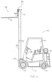
FIG. 1 is a side elevation view of a forklift incorporating moving tines using linear electric actuators in accordance with an aspect of the invention; -
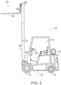
FIG. 2 is the forklift ofFIG. 1 in which a loading area having the moving tines is in an upward/raised position; -
FIG. 3 is a front view of the loading area ofFIG. 2 ; -
FIG. 4 is an isometric view of a linear electric actuator in accordance with an aspect of the invention; -
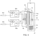
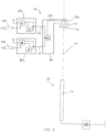
FIG. 5 is a schematic view of a charging system in a state corresponding toFIG. 1 in which the loading area is in a first or downward/lowered position and the charging system is transferring charge; -
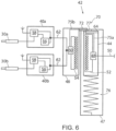
FIG. 6 is a schematic view of the charging system ofFIG. 6 in which the loading area is still in the first position, but slightly raised, and the charging system is still transferring charge; -
FIG. 7 is a schematic view of the charging system corresponding toFIG. 2 in which the loading area is in a second or upward/raised position and the charging system is no longer transferring charge; -
FIG. 8 is a side elevation view of a vehicle incorporating a charging system in accordance with another aspect of the invention, in which the power storage unit is configured to receive electrical power from the power unit when a connector is in contact with a powered rail in the first position; -
Fig. 9 is a side elevation view of the vehicle ofFig. 8 , in which the connector and the powered rail are spaced apart from or distal to one another and therefore no longer charging, and showing operation of the electronic device, such as a lighting arrangement, to illuminate a work area of the vehicle; -
Fig. 10 is a schematic view of the charging system ofFig. 8 , in which the connector and the powered rail are in contact with another, and the power unit is charging the power storage unit, in the first position; -
Fig. 11 is a schematic view of the charging system ofFig. 9 , in which the connector and the powered rail are spaced apart from or distal to one another, and the power unit is no longer charging the power storage unit, in the second position; and -
FIG. 12 is a partial isometric view illustrating an embodiment of the charging system ofFIGS. 8-11 . - In describing the embodiment of the invention which is illustrated in the drawings, specific terminology will be resorted to for the sake of clarity. However, it is not intended that the invention be limited to the specific terms so selected and it is to be understood that each specific term includes all technical equivalents which operate in a similar manner to accomplish a similar purpose. For example, the words "connected", "attached", or terms similar thereto are often used. They are not limited to direct connection but include connection through other elements where such connection is recognized as being equivalent by those skilled in the art.
- The present invention and the various features and advantageous details thereof are explained more fully with reference to the non-limiting embodiments described in detail in the following description.
- Referring now to the drawings, and specifically to
FIG. 1 , aspects of the invention are shown for use with a vehicle which could be a forklift, fork truck or similar working vehicle. The vehicle is shown here as aforklift 10. Theforklift 10 can include aframe 12 supported bywheels 14. Theframe 12 can support anoperator cab 16, anelectric power source 18, which could be charged by a conventional engine, and uprights ormasts 20. Themasts 20, in turn, can support a component, such as a cargo orloading area 22, which can include aload apron 24 and forks ortines 26. Theoperator cab 16 can include a seat for an operator, along with instrumentation and controls for monitoring and controlling theforklift 10, including operation of theloading area 22. - With additional reference to
FIG. 2 , from theoperator cab 16, an operator can drive theforklift 10 and control movement of theloading area 22 upward (shown inFIG. 2 ) or downward (shown inFIG. 1 ) with respect to themasts 20 via a set of electric or hydraulic mast actuators (not shown). With additional reference toFIG. 3 , the operator can also control movement of thetines 26 of theloading area 22, such as first andsecond tines second tines forklift 10 is operable to move objects of varying sizes by grasping such objects with thetines 26 or supporting such objects on thetines 26, raising or lowering such objects along themasts 20, and moving such objects with thewheels 14. - As shown in
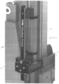
FIG. 3 , in accordance with an aspect of the invention, a set of tine actuators can include first and second linearelectric actuators electric actuators second tines masts 20. An isometric view of a representative linearelectric actuator 30 is provided inFIG. 4 . - In one aspect, the first and
second tines second retainers 32a and 32b, respectively, at upper ends of the tines for coupling to aguide bar 34 of theload apron 24. The first andsecond tines second rollers load apron 24. The first linearelectric actuator 30a can be mounted between thefirst tine 26a and theload apron 24, and the second linearelectric actuator 30b can be mounted between thesecond tine 26b and theload apron 24. Accordingly, an operator in theoperator cab 16 can control movement of thefirst tine 26a, with respect to theload apron 24, by actuating the first linearelectric actuator 30a to retract, causing thefirst tine 26a to move inward, or extend, causing thefirst tine 26a to move outward. Similarly, the operator in theoperator cab 16 can control movement of thesecond tine 26b, with respect to theload apron 24, by actuating the second linearelectric actuator 30b to retract, causing thesecond tine 26b to move inward, or extend, causing thesecond tine 26b to move outward. Moreover, the operator in theoperator cab 16 can control movement of the first andsecond tines second tines - As shown in
FIGS. 3 and 4 , in one aspect, abattery system 40 can be provided for each linearelectric actuator 30, such as afirst battery system 40a for the first linearelectric actuator 30a, and asecond battery system 40b for the second linearelectric actuator 30b. Eachbattery system 40 can be positioned proximal to its corresponding linearelectric actuator 30, such as by being directly mounted to the linearelectric actuator 30 as shown inFIG. 4 , or can be positioned further from the linearelectric actuator 30, such as by being mounted on theload apron 24. Alternatively, it is understood that a single battery system may be provided for both electric actuators. - With additional reference to
FIG. 5 , eachbattery system 40 can include a power source, such as apower storage 56, which can comprise one or more batteries, capacitors and/or other electrical or chemical charge elements for receiving electrical charge, storing electrical power and providing power to the linearelectric actuator 30. The power source can provide power to the linearelectric actuator 30 while being charged when in a downward/lowered position with respect to themasts 20. The power source can also provide power to the linearelectric actuator 30 without being charged when in an upward/raised position with respect to themasts 20. Eachbattery system 40 can also include acontrol system 58 for receiving wired or wireless commands from theoperator cab 16, such as by a wired orwireless communication device 35. Accordingly, thecontrol system 58 can be controlled by the operator in theoperator cab 16 to allow thepower storage 56 to provide a polarity, magnitude and duration of power to actuate its corresponding linearelectric actuator 30 to retract or extend by a desired amount, with eachbattery system 40 moving with its corresponding linearelectric actuator 30 as theloading area 22 is controlled to move up or down. - In accordance with an aspect of the invention, each
battery system 40 can be charged via acharging system 42. The chargingsystem 42 can include apower sending system 44 and apower receiving system 46 which can operate to charge eachbattery system 40 by wireless induction charging and/or direct (wired) contact charging. - As shown in
FIG. 1 , thepower sending system 44 can be attached, for example, to theframe 12 to be proximal to thepower receiving system 46 when theloading area 22 is in the downward/lowered position, or "first position." Thepower sending system 44 can receive power, such as from thepower source 18, and can provide power to thepower receiving system 46, when proximal to one another. Such power can be transferred wirelessly (inductively) via an electromagnetic field, or by direct power contact, when theloading area 22 is in the downward/lowered position. - Referring again to
FIG. 5 , in the first position, thepower sending system 44, proximal to thepower receiving system 46, can transfer charge inductively and/or by direct contact with thepower receiving system 46. Thepower sending system 44 can include power sending circuitry 48 configured to receive power from thepower source 18 via apower signal 50. For wirelessly (inductively) transferring charge, the power sending circuitry 48 can, in turn, generate an electrical current in aprimary coil 52 to produce an electromagnetic field and transmit power. The electromagnetic field, in turn, can induce an electrical current in a secondary coil 54 of thepower receiving system 46. The distance between thepower sending system 44 and thepower receiving system 46 in the presence of the electromagnetic field can be small, such as approximately 10 mm, which can also help to prevent dirt buildup.Power receiving circuitry 60 of thepower receiving system 46, in turn, can receive the induced electrical current from the secondary coil 54 and send charge to thepower storage 56 of eachbattery system 40 via apower signal 62. For example, thepower receiving circuitry 60 can provide thepower signal 62 to charge thepower storage 56 of thefirst battery system 40a (for powering the first linearelectric actuator 30a) and to charge thepower storage 56 of thesecond battery system 40b (for powering the second linearelectric actuator 30b). Thepower storage 56 of eachbattery system 40, in turn, can provide power to thecontrol system 58, and thecontrol system 58 can determine the polarity, magnitude and duration of power to provide to the corresponding linearelectric actuator 30. - As a result of the charging in the first position, the first and
second battery systems electric actuators loading area 22 is in an upward/raised position, or "second position," as shown inFIGS. 2 and7 , and no longer charging. - The
power sending system 44 and/or thepower receiving system 46 can be in fixed positions. However, with additional reference toFIG. 6 , thepower sending system 44 and/or thepower receiving system 46 can be configured to move a relatively small distance to maintain proximity for power transfer. In addition, if either thepower sending system 44 or thepower receiving system 46 is configured to move, alock 70 can be provided between thepower receiving system 46 and thepower sending system 44. Thelock 70 can cause thepower receiving system 46 and thepower sending system 44 to be movable together over a limited range in the first position when the lock is enabled. For example, as theload apron 24 moves with thepower receiving system 46 upward, thepower receiving system 46 can lock to thepower sending system 44 to correspondingly move the power sending system 44 a small distance in the same direction. - The
lock 70 can be magnetically and/or mechanically operated. Thelock 70 can include afirst portion 72 connected to thepower receiving system 46 and asecond portion 74 connected to thepower sending system 44. The first andsecond portions second portions lock 70 can cause thepower receiving system 46 and thepower sending system 44 to be movable together, such as over a limited range of about ± 100 mm, in order to maximize charging while in the first position. - The
lock 70 can also provide the direct contacting electrical power connection between thepower sending system 44 and thepower receiving system 46. When thefirst portion 72 is in contact with the second portion 74 (in the first position), thepower sending system 44 may transfer charge to thepower receiving system 46 accordingly. For example, thepower sending system 44 can charge thepower receiving system 46 inductively and/or by direct (wired) contact, such as by conducting an electrical current via a firstcontact power signal 75a from the power sending circuitry 48 connecting to a secondcontact power signal 75b to thepower receiving circuitry 60 via the first andsecond portions primary coil 52 and the secondary coil 54. - Either the
power receiving system 46 or thepower sending system 44 can be attached to a support mechanism via one or more springs. Such a spring can be operable to maintain positioning of thepower receiving system 46 and/or thepower sending system 44 through a limited range with respect to the support mechanism when in the first position. For example, aspring 76 can be connected to thepower sending system 44 to maintain thepower sending system 44 in the first position (with the power receiving system 46) through a limited range with respect to the second support mechanism. Accordingly, the first position can be maintained until overcoming a tension of thespring 76 and/or reaching astop 77. As such, thespring 76 can operate from a compressed condition, as illustrated inFIG. 5 , to an extended condition, as illustrated inFIG. 6 . For example, when lifting theloading area 22, thelock 70 can lift thepower sending system 44, extending thespring 76, until a tension of thespring 76 is overcome and/or thepower sending system 44 reaches thestop 77. Then, thelock 70 can disable, and thepower receiving system 46 can continue to travel upwards with theloading area 22, away from thepower sending system 44. In a subsequent lock operation, such as when theloading area 22 is lowered and thepower receiving system 46 is again in proximity to thepower sending system 44, thelock 70 can enable again and overcome the force of thespring 76 to drag thepower sending system 44 along with thepower receiving system 46 while charging. - Accordingly, in one aspect, upon reaching the extended condition, the
spring 76 can cause a tension sufficient to overcome thelock 70. As a result, thespring 76 can cause thepower sending system 44 to pull away from the power receiving system 46 (disabling the lock 70) and into the second position, as illustrated inFIG. 7 , Upon disabling of thelock 70, in the second position, thepower sending system 44 can become distal to thepower receiving system 46, thereby disrupting charging of thepower receiving system 46. In addition, thespring 76 can cause thepower sending system 44 to return to an equilibrium position for a subsequent lock operation between thepower sending system 44 and thepower receiving system 46 when moving again into proximity. Also, in another aspect, thestop 77 can prevent thepower sending system 44 from further travel, thereby overcoming thelock 70 and causing thepower sending system 44 to return to the equilibrium position via thespring 76 for a subsequent lock operation. - The present invention has been shown with the
spring 76 connected to thepower sending system 44. It should be appreciated, however, that a spring may in addition, or alternatively, be connected to thepower receiving system 46. Accordingly, other alternative configurations can be employed as desired without departing from the scope of the invention as set forth above. In addition, while the present invention has been shown and described with respect to thepower receiving system 46 being employed to power an electrical device remotely from thepower sending system 44, it is understood that the present invention contemplates providing power to any type of powered component or device carried by or secured to a movable component of a vehicle and is not limited to electrical devices. - Referring now to
Fig. 8 , where like reference numerals refer to like parts where possible, a side elevation view of thevehicle 10 incorporating a charging system in accordance with another aspect of the invention is provided. In particular, thebattery system 40 is configured to receive electrical power from a when aconnector 102 of thebattery system 40 is in contact with apowered rail 104 in the first position as shown. Thebattery system 40 and theconnector 102 can be attached to theloading area 22, while thepowered rail 104 is attached to the one of themasts 20, as shown. Accordingly, theconnector 102 can move along thepowered rail 104 with electrical contact through a length of thepowered rail 104 in the first position. Accordingly, direct contact charging of thepower battery system 40 can be achieved in the first position. - Representatively, by way of example, the
connector 102 can be configured to move with direct contact to thepowered rail 104 through a distance, which may preferably be less than about 20% of the travel distance of theloading area 22 with respect to themasts 20. In one aspect, thepowered rail 104 could be a rigid conductor having a length of about 1 meter disposed in a direction of motion betweenloading area 22 and themasts 20. - With additional reference to
Fig. 9 , when theconnector 102 is spaced apart from thepowered rail 104 in the second position as shown, thebattery system 40 no longer receives electrical power from thepower sending system 44. Nevertheless, theelectric actuators battery system 40. - Referring now to
Fig. 10 , a schematic view of the charging system ofFig. 8 is provided. Shown in the first position, theconnector 102 and thepowered rail 104 are in direct electrical contact with one another. As a result, thebattery system 40 receives electrical power from thepower sending system 44 in a charging state. In one aspect, thepower sending system 44 can provide Direct Current (DC) electrical power to thepowered rail 104, which, in turn, can be received by thebattery system 40 for electrical charging. - The
connector 102 can move along anaxis 105, in a direction of motion between theloading area 22 and themasts 20. While in the first position, direct contact charging can be provided at an interface between thepowered rail 104 and an electrically conductive surface 106 of theconnector 102. Such direct contact charging can be maintained while traveling through the length of thepowered rail 104 with the electrically conductive surface 106 sliding along thepowered rail 104. Theconnector 102 can be further configured to move with direct contact to thepowered rail 104 using one ormore guide wheels 108. The electrically conductive surface 106 can maximize transfer and conduction of electrical power from thepowered rail 104 tobattery system 40 when in direct contact with thepowered rail 104 by providing a large, substantially flat, conductive surface area for contacting thepowered rail 104. The electrically conductive surface 106 can, in turn, connect to the powerstorage unit circuitry 60, for example, via the secondcontact power signal 75b. It should be appreciated that wireless inductive charging could also be included in this embodiment for additional charging ability by implementation and alignment of the primary andsecondary coils 52 and 54, respectively. - Referring now to
Fig. 11 , a schematic view of the charging system ofFig. 9 is provided. Shown in the second position, theconnector 102 and thepowered rail 104 are no longer in electrical contact with one another. As a result, thebattery system 40 no longer receives electrical power from the sendingsystem 44. Instead, thebattery system 40 and theconnector 102 are moved along theaxis 105, away from thepowered rail 104, such as to accomplish a work function. Nevertheless, theactuators
Claims (13)
- A system for use on a work vehicle (10), comprising:a component (22) configured to lower in a first position and raise in a second position;a linear electric actuator (30, 30a, 30b) configured to move a portion (26, 26a, 26b) of the component (22) when in the first position or the second position; anda power source (56) for providing power to the linear electric actuator (30, 30a, 30b) for moving the portion (26, 26a, 26b), wherein the power source (56) provides power while being charged when in the first position and provides power without being charged when in the second position,masts (20), wherein the component (22) is configured to lower in the first position and raise in the second position with respect to the masts (20);characterised in that the system further comprises:
a power sending system (44), a power receiving system (46) and a lock (70) between the power sending system (44) and the power receiving system (46), wherein the power sending system (44) and the power receiving system (46) charge the power source (56), wherein the power sending system (44) is stationary in the first and second positions and the power receiving system (46) moves with the component (22), and wherein the power sending system (44) and the power receiving system (46) are movable together in the first position when the lock (70) is enabled. - The system of claim 1, wherein the linear electric actuator (30, 30a, 30b) is a first linear electric actuator (30a) configured to move a first tine (26a) of a loading area (22), and further comprising a second linear electric actuator (30b) configured to move a second tine (26b) of a loading area (22).
- The system of claim 1, wherein the power sending system (44) is further configured to provide power to the power receiving system (46) by direct wired contact when the lock (70) is enabled.
- The system of claim 1, further comprising a spring (76), wherein at least one of the power sending system (44) and the power receiving system (46) is attached to the spring (76).
- The system of claim 2, wherein the first and second linear electric actuators (30a, 30b) are configured to move the first and second tines (26a, 26b), respectively, inward or outward with respect to one another.
- The system of claim 2, wherein the power source (56) is a first power source (56), and further comprising a second power source (56) for providing power to the second linear electric actuator (30b) for moving the portion (26, 26a, 26b), wherein the second power source (56) provides power while being charged when in the first position and provides power without being charged when in the second position, and wherein the first and second power sources (56) are mounted to the first and second linear electric actuators (30a, 30b), respectively.
- The system of claim 6, further comprising a wireless communication device (35), wherein the wireless communication device (35) is operable to control the first and second power sources (56).
- The system of claim 1, wherein the component (22) is a loading area (22) and the portion (26, 26a, 26b) comprises first and second tines (26a, 26b) of the loading area (22), and wherein the first and second tines (26a, 26b) are configured to move individually with respect to one another.
- The system of claim 1, wherein the component (22) is a loading area (22) and the portion (26, 26a, 26b) comprises first and second tines (26a, 26b) of the loading area (22), and wherein the first and second tines (26a, 26b) are configured to move in cooperation with one another to achieve symmetrical spacing between the first and second tines.
- A method for moving tines (26, 26a, 26b) on a forklift (10), comprising:providing power from a power sending system (44) to a power receiving system (46), the power sending system (44) comprising a primary coil (52) and the power receiving system (46) comprising a secondary coil (54), wherein the power is provided between the primary and secondary coils (52, 54) via electromagnetic induction, and wherein the power is provided when the power sending system (44) is proximal to the power receiving system (46) in a first position; andcharging a battery system (40, 40a, 40b) from the power receiving system (46) when in the first position,characterised in that the method further comprises providing power to first and second linear electric actuators (30a, 30b) configured to move first and second tines (26a, 26b), respectively, from the battery system (40, 40a, 40b); andenabling a lock (70) between the power sending system (44) and the power receiving system (46) so that the power sending system (44) and the power receiving system (46) are movable together in the first position when the lock (70) is enabled.
- The method of claim 10, further comprising moving the first and second tines (26a, 26b) individually with respect to one another.
- The method of claim 10, further comprising moving the first and second tines (26a, 26b) in cooperation with one another to achieve symmetrical spacing between the first and second tines (26a, 26b).
- A work vehicle (10), comprising:an operator cab (16) supported by a frame (12) and wheels (14);masts (20) supported by the frame (12);a loading area (22) supported by the masts (20), the loading area (22) having first and second tines (26a, 26b); anda charging system (42) comprising a power sending system (44) and a power receiving system (46), wherein the power sending system (44) is configured to provide power to the power receiving system (46) when the power sending system (44) is proximal to the power receiving system (46) in a first position in which the loading area is downward with respect to the masts (20),characterised in that the work vehicle (10) further comprises first and second linear electric actuators (30a, 30b) for moving the first and second tines (26a, 26b), respectively;a battery system (40, 40a, 40b) configured to provide power to the first and second linear electric actuators (30a, 30b), wherein the power receiving system (46) is configured to charge the battery system (40, 40a, 40b) when in the first position;a second position in which the loading area (22) is upward with respect to the masts (20), wherein the power sending system (44) is distal to the power receiving system (46) and the power sending system (44) no longer provides power to the power receiving system (46); anda lock (70) between the power sending system (44) and the power receiving system (46), wherein the power sending system (44) and the power receiving system (46) are movable together in the first position when the lock (70) is enabled.
Applications Claiming Priority (3)
| Application Number | Priority Date | Filing Date | Title |
|---|---|---|---|
| US201762481264P | 2017-04-04 | 2017-04-04 | |
| US15/944,358 US10501298B2 (en) | 2017-04-04 | 2018-04-03 | Linear actuator system for moving tines of a work vehicle |
| PCT/US2018/026008 WO2018187417A1 (en) | 2017-04-04 | 2018-04-04 | Linear actuator system for moving tines of a work vehicle |
Publications (2)
| Publication Number | Publication Date |
|---|---|
| EP3606864A1 EP3606864A1 (en) | 2020-02-12 |
| EP3606864B1 true EP3606864B1 (en) | 2024-06-19 |
Family
ID=63672166
Family Applications (1)
| Application Number | Title | Priority Date | Filing Date |
|---|---|---|---|
| EP18720828.5A Active EP3606864B1 (en) | 2017-04-04 | 2018-04-04 | Linear actuator system for moving tines of a work vehicle |
Country Status (5)
| Country | Link |
|---|---|
| US (1) | US10501298B2 (en) |
| EP (1) | EP3606864B1 (en) |
| JP (1) | JP7178359B2 (en) |
| FI (1) | FI3606864T3 (en) |
| WO (1) | WO2018187417A1 (en) |
Families Citing this family (3)
| Publication number | Priority date | Publication date | Assignee | Title |
|---|---|---|---|---|
| CN109095401A (en) * | 2018-10-10 | 2018-12-28 | 浙江亚鼎科技有限公司 | A kind of charging unit of forklift door frame instrument |
| US12180672B2 (en) | 2020-03-02 | 2024-12-31 | Doosan Bobcat North America, Inc. | Electrically powered power machine |
| CA3220521A1 (en) | 2021-09-02 | 2023-03-09 | Brent DURKIN | Lift arm arrangements for power machines |
Family Cites Families (25)
| Publication number | Priority date | Publication date | Assignee | Title |
|---|---|---|---|---|
| US3543959A (en) * | 1969-02-17 | 1970-12-01 | Crown Controls Corp | Lift truck mechanism |
| US4252217A (en) | 1978-02-28 | 1981-02-24 | Litton Systems, Inc. | Semi-automated warehousing system |
| US5139385A (en) | 1990-04-03 | 1992-08-18 | Swingshift Manufacturing, Inc. | Dual pallet fork attachment for a lift truck |
| US5326217A (en) | 1990-09-24 | 1994-07-05 | Clark Material Handling Company | Lift truck with negative drop upright |
| US6430761B1 (en) | 1999-01-25 | 2002-08-13 | Take-Along Lifts Llc | Compact portable patient lift |
| JP2002302395A (en) * | 2001-04-05 | 2002-10-18 | Nippon Yusoki Co Ltd | Electric switch |
| SE521188C2 (en) | 2002-02-11 | 2003-10-07 | Kalmar Ind Sverige Ab | Hydraulic system for a vehicle, a vehicle comprising such a hydraulic system and an additional unit for such a vehicle |
| JP2004338869A (en) * | 2003-05-15 | 2004-12-02 | Kaga Sangyo Sharyo:Kk | Movable fork unit of forklift vehicle |
| JP4288245B2 (en) | 2005-02-25 | 2009-07-01 | 三菱重工業株式会社 | Forklift and induction motor control method applied thereto |
| US20060255943A1 (en) * | 2005-05-16 | 2006-11-16 | Psc Scanning, Inc. | Induction charging machine, methods, and system for a data reader |
| AU2006267041B2 (en) | 2005-07-13 | 2011-07-21 | Crown Equipment Corporation | Pallet clamping device |
| CA2677836C (en) | 2007-02-16 | 2016-06-21 | Ecb Novatech Inc. | Gripping device for load structure |
| MX2010012169A (en) | 2008-05-08 | 2011-05-19 | Attachment Technologies Inc | Fork apparatus for handling cotton bales. |
| JP2010112409A (en) * | 2008-11-05 | 2010-05-20 | Hitachi Constr Mach Co Ltd | Linear actuator |
| JP5319320B2 (en) * | 2009-02-17 | 2013-10-16 | 日立建機株式会社 | forklift |
| US20100327544A1 (en) | 2009-06-29 | 2010-12-30 | Richard Allen Pebworth | Cylinder Cart |
| US8869944B2 (en) * | 2010-03-01 | 2014-10-28 | The Raymond Corporation | Energy storage on an elevated platform and transfer method |
| CN104125924B (en) | 2012-02-20 | 2016-06-29 | 艾玛斯布达有限公司 | Side-lift sling |
| EP2628703A1 (en) | 2012-02-20 | 2013-08-21 | Elme Spreader AB | Side lift spreader |
| DE102012021043A1 (en) | 2012-10-26 | 2014-04-30 | Jungheinrich Aktiengesellschaft | Industrial truck has electrical generator that is arranged between first and second components and is driven mechanically relative to one another upon movement of components, to partially feed electrical load |
| JP5286445B1 (en) | 2012-12-28 | 2013-09-11 | 株式会社日立パワーソリューションズ | Wireless power feeder for electric mobile body |
| WO2014128928A1 (en) * | 2013-02-22 | 2014-08-28 | ニチュ三菱フォークリフト株式会社 | Cargo vehicle, and method of charging mast-side bracket power source in cargo vehicle |
| US9935469B2 (en) * | 2015-02-10 | 2018-04-03 | Cascade Corporation | Wireless power transfer and communications for industrial equipment |
| US10414359B2 (en) * | 2015-02-16 | 2019-09-17 | Tyri International, Inc. | System for providing wireless operation of powered device(s) on a vehicle |
| US9525288B2 (en) | 2015-02-26 | 2016-12-20 | Cascade Corporation | Devices and methods for inductive power transfer and power control for industrial equipment |
-
2018
- 2018-04-03 US US15/944,358 patent/US10501298B2/en active Active
- 2018-04-04 WO PCT/US2018/026008 patent/WO2018187417A1/en not_active Ceased
- 2018-04-04 JP JP2019554643A patent/JP7178359B2/en active Active
- 2018-04-04 FI FIEP18720828.5T patent/FI3606864T3/en active
- 2018-04-04 EP EP18720828.5A patent/EP3606864B1/en active Active
Also Published As
| Publication number | Publication date |
|---|---|
| US20180282141A1 (en) | 2018-10-04 |
| US10501298B2 (en) | 2019-12-10 |
| FI3606864T3 (en) | 2024-07-03 |
| JP2020515486A (en) | 2020-05-28 |
| JP7178359B2 (en) | 2022-11-25 |
| WO2018187417A1 (en) | 2018-10-11 |
| EP3606864A1 (en) | 2020-02-12 |
Similar Documents
| Publication | Publication Date | Title |
|---|---|---|
| US8025474B2 (en) | Battery-changing vehicle with cantilevered boom | |
| EP3606864B1 (en) | Linear actuator system for moving tines of a work vehicle | |
| KR102612778B1 (en) | Inductive energy transfer method and apparatus for operating the inductive energy transfer device | |
| JP6647313B2 (en) | Induction power transmission apparatus and method, and power control for industrial equipment | |
| EP3112312A1 (en) | Telehandler | |
| US10680678B2 (en) | System for providing wireless operation of powered device(s) on a vehicle with direct charging | |
| US12043100B2 (en) | Telehandler with improved stabilisers | |
| CN116101095A (en) | Material handling vehicle charging system and method with position compensation | |
| US10414359B2 (en) | System for providing wireless operation of powered device(s) on a vehicle | |
| JP2023082056A (en) | A system that enables wireless operation of one or more powered devices on a vehicle by direct charging. | |
| AU2024278324B2 (en) | Tire handler having tire lay flat capability | |
| EP3953275B1 (en) | Container handling vehicle and method | |
| US8240683B1 (en) | Portable hand truck with powered lifting device | |
| US11524584B2 (en) | Current collector arrangement for a vehicle and a vehicle therefore | |
| US20070003395A1 (en) | Device in a vehicle adapted to handle loads | |
| EP3812339A1 (en) | Material handling vehicle | |
| EP3653434B1 (en) | Dumper with variable track width | |
| JPH074500U (en) | Safety equipment for aerial work vehicles |
Legal Events
| Date | Code | Title | Description |
|---|---|---|---|
| STAA | Information on the status of an ep patent application or granted ep patent |
Free format text: STATUS: UNKNOWN |
|
| STAA | Information on the status of an ep patent application or granted ep patent |
Free format text: STATUS: THE INTERNATIONAL PUBLICATION HAS BEEN MADE |
|
| PUAI | Public reference made under article 153(3) epc to a published international application that has entered the european phase |
Free format text: ORIGINAL CODE: 0009012 |
|
| STAA | Information on the status of an ep patent application or granted ep patent |
Free format text: STATUS: REQUEST FOR EXAMINATION WAS MADE |
|
| 17P | Request for examination filed |
Effective date: 20191001 |
|
| AK | Designated contracting states |
Kind code of ref document: A1 Designated state(s): AL AT BE BG CH CY CZ DE DK EE ES FI FR GB GR HR HU IE IS IT LI LT LU LV MC MK MT NL NO PL PT RO RS SE SI SK SM TR |
|
| AX | Request for extension of the european patent |
Extension state: BA ME |
|
| DAV | Request for validation of the european patent (deleted) | ||
| DAX | Request for extension of the european patent (deleted) | ||
| RIC1 | Information provided on ipc code assigned before grant |
Ipc: H02J 7/00 20060101ALI20220729BHEP Ipc: B66F 9/14 20060101ALI20220729BHEP Ipc: B66F 9/075 20060101ALI20220729BHEP Ipc: H02J 7/34 20060101ALI20220729BHEP Ipc: B66F 9/24 20060101AFI20220729BHEP |
|
| STAA | Information on the status of an ep patent application or granted ep patent |
Free format text: STATUS: EXAMINATION IS IN PROGRESS |
|
| 17Q | First examination report despatched |
Effective date: 20220930 |
|
| GRAP | Despatch of communication of intention to grant a patent |
Free format text: ORIGINAL CODE: EPIDOSNIGR1 |
|
| STAA | Information on the status of an ep patent application or granted ep patent |
Free format text: STATUS: GRANT OF PATENT IS INTENDED |
|
| INTG | Intention to grant announced |
Effective date: 20240202 |
|
| GRAS | Grant fee paid |
Free format text: ORIGINAL CODE: EPIDOSNIGR3 |
|
| GRAA | (expected) grant |
Free format text: ORIGINAL CODE: 0009210 |
|
| STAA | Information on the status of an ep patent application or granted ep patent |
Free format text: STATUS: THE PATENT HAS BEEN GRANTED |
|
| P01 | Opt-out of the competence of the unified patent court (upc) registered |
Effective date: 20240417 |
|
| AK | Designated contracting states |
Kind code of ref document: B1 Designated state(s): AL AT BE BG CH CY CZ DE DK EE ES FI FR GB GR HR HU IE IS IT LI LT LU LV MC MK MT NL NO PL PT RO RS SE SI SK SM TR |
|
| REG | Reference to a national code |
Ref country code: GB Ref legal event code: FG4D |
|
| REG | Reference to a national code |
Ref country code: CH Ref legal event code: EP |
|
| REG | Reference to a national code |
Ref country code: FI Ref legal event code: FGE |
|
| REG | Reference to a national code |
Ref country code: DE Ref legal event code: R096 Ref document number: 602018070758 Country of ref document: DE |
|
| REG | Reference to a national code |
Ref country code: SE Ref legal event code: TRGR |
|
| PG25 | Lapsed in a contracting state [announced via postgrant information from national office to epo] |
Ref country code: BG Free format text: LAPSE BECAUSE OF FAILURE TO SUBMIT A TRANSLATION OF THE DESCRIPTION OR TO PAY THE FEE WITHIN THE PRESCRIBED TIME-LIMIT Effective date: 20240619 |
|
| PG25 | Lapsed in a contracting state [announced via postgrant information from national office to epo] |
Ref country code: HR Free format text: LAPSE BECAUSE OF FAILURE TO SUBMIT A TRANSLATION OF THE DESCRIPTION OR TO PAY THE FEE WITHIN THE PRESCRIBED TIME-LIMIT Effective date: 20240619 |
|
| REG | Reference to a national code |
Ref country code: LT Ref legal event code: MG9D |
|
| PG25 | Lapsed in a contracting state [announced via postgrant information from national office to epo] |
Ref country code: GR Free format text: LAPSE BECAUSE OF FAILURE TO SUBMIT A TRANSLATION OF THE DESCRIPTION OR TO PAY THE FEE WITHIN THE PRESCRIBED TIME-LIMIT Effective date: 20240920 |
|
| PG25 | Lapsed in a contracting state [announced via postgrant information from national office to epo] |
Ref country code: LV Free format text: LAPSE BECAUSE OF FAILURE TO SUBMIT A TRANSLATION OF THE DESCRIPTION OR TO PAY THE FEE WITHIN THE PRESCRIBED TIME-LIMIT Effective date: 20240619 |
|
| PG25 | Lapsed in a contracting state [announced via postgrant information from national office to epo] |
Ref country code: NO Free format text: LAPSE BECAUSE OF FAILURE TO SUBMIT A TRANSLATION OF THE DESCRIPTION OR TO PAY THE FEE WITHIN THE PRESCRIBED TIME-LIMIT Effective date: 20240919 Ref country code: LV Free format text: LAPSE BECAUSE OF FAILURE TO SUBMIT A TRANSLATION OF THE DESCRIPTION OR TO PAY THE FEE WITHIN THE PRESCRIBED TIME-LIMIT Effective date: 20240619 Ref country code: HR Free format text: LAPSE BECAUSE OF FAILURE TO SUBMIT A TRANSLATION OF THE DESCRIPTION OR TO PAY THE FEE WITHIN THE PRESCRIBED TIME-LIMIT Effective date: 20240619 Ref country code: GR Free format text: LAPSE BECAUSE OF FAILURE TO SUBMIT A TRANSLATION OF THE DESCRIPTION OR TO PAY THE FEE WITHIN THE PRESCRIBED TIME-LIMIT Effective date: 20240920 Ref country code: BG Free format text: LAPSE BECAUSE OF FAILURE TO SUBMIT A TRANSLATION OF THE DESCRIPTION OR TO PAY THE FEE WITHIN THE PRESCRIBED TIME-LIMIT Effective date: 20240619 Ref country code: RS Free format text: LAPSE BECAUSE OF FAILURE TO SUBMIT A TRANSLATION OF THE DESCRIPTION OR TO PAY THE FEE WITHIN THE PRESCRIBED TIME-LIMIT Effective date: 20240919 |
|
| PG25 | Lapsed in a contracting state [announced via postgrant information from national office to epo] |
Ref country code: NL Free format text: LAPSE BECAUSE OF FAILURE TO SUBMIT A TRANSLATION OF THE DESCRIPTION OR TO PAY THE FEE WITHIN THE PRESCRIBED TIME-LIMIT Effective date: 20240619 |
|
| REG | Reference to a national code |
Ref country code: AT Ref legal event code: MK05 Ref document number: 1695820 Country of ref document: AT Kind code of ref document: T Effective date: 20240619 |
|
| PG25 | Lapsed in a contracting state [announced via postgrant information from national office to epo] |
Ref country code: NL Free format text: LAPSE BECAUSE OF FAILURE TO SUBMIT A TRANSLATION OF THE DESCRIPTION OR TO PAY THE FEE WITHIN THE PRESCRIBED TIME-LIMIT Effective date: 20240619 |
|
| PG25 | Lapsed in a contracting state [announced via postgrant information from national office to epo] |
Ref country code: PT Free format text: LAPSE BECAUSE OF FAILURE TO SUBMIT A TRANSLATION OF THE DESCRIPTION OR TO PAY THE FEE WITHIN THE PRESCRIBED TIME-LIMIT Effective date: 20241021 |
|
| PG25 | Lapsed in a contracting state [announced via postgrant information from national office to epo] |
Ref country code: PT Free format text: LAPSE BECAUSE OF FAILURE TO SUBMIT A TRANSLATION OF THE DESCRIPTION OR TO PAY THE FEE WITHIN THE PRESCRIBED TIME-LIMIT Effective date: 20241021 |
|
| PG25 | Lapsed in a contracting state [announced via postgrant information from national office to epo] |
Ref country code: PL Free format text: LAPSE BECAUSE OF FAILURE TO SUBMIT A TRANSLATION OF THE DESCRIPTION OR TO PAY THE FEE WITHIN THE PRESCRIBED TIME-LIMIT Effective date: 20240619 |
|
| PG25 | Lapsed in a contracting state [announced via postgrant information from national office to epo] |
Ref country code: EE Free format text: LAPSE BECAUSE OF FAILURE TO SUBMIT A TRANSLATION OF THE DESCRIPTION OR TO PAY THE FEE WITHIN THE PRESCRIBED TIME-LIMIT Effective date: 20240619 |
|
| PG25 | Lapsed in a contracting state [announced via postgrant information from national office to epo] |
Ref country code: IS Free format text: LAPSE BECAUSE OF FAILURE TO SUBMIT A TRANSLATION OF THE DESCRIPTION OR TO PAY THE FEE WITHIN THE PRESCRIBED TIME-LIMIT Effective date: 20241019 Ref country code: AT Free format text: LAPSE BECAUSE OF FAILURE TO SUBMIT A TRANSLATION OF THE DESCRIPTION OR TO PAY THE FEE WITHIN THE PRESCRIBED TIME-LIMIT Effective date: 20240619 |
|
| PG25 | Lapsed in a contracting state [announced via postgrant information from national office to epo] |
Ref country code: CZ Free format text: LAPSE BECAUSE OF FAILURE TO SUBMIT A TRANSLATION OF THE DESCRIPTION OR TO PAY THE FEE WITHIN THE PRESCRIBED TIME-LIMIT Effective date: 20240619 |
|
| PG25 | Lapsed in a contracting state [announced via postgrant information from national office to epo] |
Ref country code: RO Free format text: LAPSE BECAUSE OF FAILURE TO SUBMIT A TRANSLATION OF THE DESCRIPTION OR TO PAY THE FEE WITHIN THE PRESCRIBED TIME-LIMIT Effective date: 20240619 Ref country code: SK Free format text: LAPSE BECAUSE OF FAILURE TO SUBMIT A TRANSLATION OF THE DESCRIPTION OR TO PAY THE FEE WITHIN THE PRESCRIBED TIME-LIMIT Effective date: 20240619 |
|
| PG25 | Lapsed in a contracting state [announced via postgrant information from national office to epo] |
Ref country code: ES Free format text: LAPSE BECAUSE OF FAILURE TO SUBMIT A TRANSLATION OF THE DESCRIPTION OR TO PAY THE FEE WITHIN THE PRESCRIBED TIME-LIMIT Effective date: 20240619 Ref country code: SM Free format text: LAPSE BECAUSE OF FAILURE TO SUBMIT A TRANSLATION OF THE DESCRIPTION OR TO PAY THE FEE WITHIN THE PRESCRIBED TIME-LIMIT Effective date: 20240619 |
|
| PG25 | Lapsed in a contracting state [announced via postgrant information from national office to epo] |
Ref country code: SM Free format text: LAPSE BECAUSE OF FAILURE TO SUBMIT A TRANSLATION OF THE DESCRIPTION OR TO PAY THE FEE WITHIN THE PRESCRIBED TIME-LIMIT Effective date: 20240619 Ref country code: SK Free format text: LAPSE BECAUSE OF FAILURE TO SUBMIT A TRANSLATION OF THE DESCRIPTION OR TO PAY THE FEE WITHIN THE PRESCRIBED TIME-LIMIT Effective date: 20240619 Ref country code: RO Free format text: LAPSE BECAUSE OF FAILURE TO SUBMIT A TRANSLATION OF THE DESCRIPTION OR TO PAY THE FEE WITHIN THE PRESCRIBED TIME-LIMIT Effective date: 20240619 Ref country code: PL Free format text: LAPSE BECAUSE OF FAILURE TO SUBMIT A TRANSLATION OF THE DESCRIPTION OR TO PAY THE FEE WITHIN THE PRESCRIBED TIME-LIMIT Effective date: 20240619 Ref country code: IS Free format text: LAPSE BECAUSE OF FAILURE TO SUBMIT A TRANSLATION OF THE DESCRIPTION OR TO PAY THE FEE WITHIN THE PRESCRIBED TIME-LIMIT Effective date: 20241019 Ref country code: ES Free format text: LAPSE BECAUSE OF FAILURE TO SUBMIT A TRANSLATION OF THE DESCRIPTION OR TO PAY THE FEE WITHIN THE PRESCRIBED TIME-LIMIT Effective date: 20240619 Ref country code: EE Free format text: LAPSE BECAUSE OF FAILURE TO SUBMIT A TRANSLATION OF THE DESCRIPTION OR TO PAY THE FEE WITHIN THE PRESCRIBED TIME-LIMIT Effective date: 20240619 Ref country code: CZ Free format text: LAPSE BECAUSE OF FAILURE TO SUBMIT A TRANSLATION OF THE DESCRIPTION OR TO PAY THE FEE WITHIN THE PRESCRIBED TIME-LIMIT Effective date: 20240619 Ref country code: AT Free format text: LAPSE BECAUSE OF FAILURE TO SUBMIT A TRANSLATION OF THE DESCRIPTION OR TO PAY THE FEE WITHIN THE PRESCRIBED TIME-LIMIT Effective date: 20240619 |
|
| REG | Reference to a national code |
Ref country code: DE Ref legal event code: R097 Ref document number: 602018070758 Country of ref document: DE |
|
| PG25 | Lapsed in a contracting state [announced via postgrant information from national office to epo] |
Ref country code: DK Free format text: LAPSE BECAUSE OF FAILURE TO SUBMIT A TRANSLATION OF THE DESCRIPTION OR TO PAY THE FEE WITHIN THE PRESCRIBED TIME-LIMIT Effective date: 20240619 |
|
| PLBE | No opposition filed within time limit |
Free format text: ORIGINAL CODE: 0009261 |
|
| STAA | Information on the status of an ep patent application or granted ep patent |
Free format text: STATUS: NO OPPOSITION FILED WITHIN TIME LIMIT |
|
| 26N | No opposition filed |
Effective date: 20250320 |
|
| PGFP | Annual fee paid to national office [announced via postgrant information from national office to epo] |
Ref country code: FI Payment date: 20250424 Year of fee payment: 8 |
|
| PGFP | Annual fee paid to national office [announced via postgrant information from national office to epo] |
Ref country code: DE Payment date: 20250422 Year of fee payment: 8 |
|
| PGFP | Annual fee paid to national office [announced via postgrant information from national office to epo] |
Ref country code: GB Payment date: 20250403 Year of fee payment: 8 |
|
| PGFP | Annual fee paid to national office [announced via postgrant information from national office to epo] |
Ref country code: IT Payment date: 20250422 Year of fee payment: 8 |
|
| PGFP | Annual fee paid to national office [announced via postgrant information from national office to epo] |
Ref country code: FR Payment date: 20250425 Year of fee payment: 8 |
|
| PGFP | Annual fee paid to national office [announced via postgrant information from national office to epo] |
Ref country code: SE Payment date: 20250429 Year of fee payment: 8 |
|
| REG | Reference to a national code |
Ref country code: CH Ref legal event code: H13 Free format text: ST27 STATUS EVENT CODE: U-0-0-H10-H13 (AS PROVIDED BY THE NATIONAL OFFICE) Effective date: 20251125 |
|
| PG25 | Lapsed in a contracting state [announced via postgrant information from national office to epo] |
Ref country code: LU Free format text: LAPSE BECAUSE OF NON-PAYMENT OF DUE FEES Effective date: 20250404 |
|
| PG25 | Lapsed in a contracting state [announced via postgrant information from national office to epo] |
Ref country code: MC Free format text: LAPSE BECAUSE OF FAILURE TO SUBMIT A TRANSLATION OF THE DESCRIPTION OR TO PAY THE FEE WITHIN THE PRESCRIBED TIME-LIMIT Effective date: 20240619 |
|
| REG | Reference to a national code |
Ref country code: BE Ref legal event code: MM Effective date: 20250430 |
|
| PG25 | Lapsed in a contracting state [announced via postgrant information from national office to epo] |
Ref country code: BE Free format text: LAPSE BECAUSE OF NON-PAYMENT OF DUE FEES Effective date: 20250430 |
|
| PG25 | Lapsed in a contracting state [announced via postgrant information from national office to epo] |
Ref country code: CH Free format text: LAPSE BECAUSE OF NON-PAYMENT OF DUE FEES Effective date: 20250430 |
|
| PG25 | Lapsed in a contracting state [announced via postgrant information from national office to epo] |
Ref country code: IE Free format text: LAPSE BECAUSE OF NON-PAYMENT OF DUE FEES Effective date: 20250404 |