EP3606446B1 - Surgical handle assembly - Google Patents
Surgical handle assembly Download PDFInfo
- Publication number
- EP3606446B1 EP3606446B1 EP18781498.3A EP18781498A EP3606446B1 EP 3606446 B1 EP3606446 B1 EP 3606446B1 EP 18781498 A EP18781498 A EP 18781498A EP 3606446 B1 EP3606446 B1 EP 3606446B1
- Authority
- EP
- European Patent Office
- Prior art keywords
- mode
- distance
- pin
- movable handle
- handle member
- Prior art date
- Legal status (The legal status is an assumption and is not a legal conclusion. Google has not performed a legal analysis and makes no representation as to the accuracy of the status listed.)
- Active
Links
Images



Classifications
-
- A—HUMAN NECESSITIES
- A61—MEDICAL OR VETERINARY SCIENCE; HYGIENE
- A61B—DIAGNOSIS; SURGERY; IDENTIFICATION
- A61B17/00—Surgical instruments, devices or methods
- A61B17/068—Surgical staplers, e.g. containing multiple staples or clamps
- A61B17/072—Surgical staplers, e.g. containing multiple staples or clamps for applying a row of staples in a single action, e.g. the staples being applied simultaneously
- A61B17/07207—Surgical staplers, e.g. containing multiple staples or clamps for applying a row of staples in a single action, e.g. the staples being applied simultaneously the staples being applied sequentially
-
- A—HUMAN NECESSITIES
- A61—MEDICAL OR VETERINARY SCIENCE; HYGIENE
- A61B—DIAGNOSIS; SURGERY; IDENTIFICATION
- A61B17/00—Surgical instruments, devices or methods
- A61B17/068—Surgical staplers, e.g. containing multiple staples or clamps
- A61B17/072—Surgical staplers, e.g. containing multiple staples or clamps for applying a row of staples in a single action, e.g. the staples being applied simultaneously
-
- A—HUMAN NECESSITIES
- A61—MEDICAL OR VETERINARY SCIENCE; HYGIENE
- A61B—DIAGNOSIS; SURGERY; IDENTIFICATION
- A61B17/00—Surgical instruments, devices or methods
- A61B17/068—Surgical staplers, e.g. containing multiple staples or clamps
-
- A—HUMAN NECESSITIES
- A61—MEDICAL OR VETERINARY SCIENCE; HYGIENE
- A61B—DIAGNOSIS; SURGERY; IDENTIFICATION
- A61B17/00—Surgical instruments, devices or methods
- A61B2017/0023—Surgical instruments, devices or methods disposable
-
- A—HUMAN NECESSITIES
- A61—MEDICAL OR VETERINARY SCIENCE; HYGIENE
- A61B—DIAGNOSIS; SURGERY; IDENTIFICATION
- A61B17/00—Surgical instruments, devices or methods
- A61B2017/00367—Details of actuation of instruments, e.g. relations between pushing buttons, or the like, and activation of the tool, working tip, or the like
-
- A—HUMAN NECESSITIES
- A61—MEDICAL OR VETERINARY SCIENCE; HYGIENE
- A61B—DIAGNOSIS; SURGERY; IDENTIFICATION
- A61B17/00—Surgical instruments, devices or methods
- A61B2017/00367—Details of actuation of instruments, e.g. relations between pushing buttons, or the like, and activation of the tool, working tip, or the like
- A61B2017/00407—Ratchet means
-
- A—HUMAN NECESSITIES
- A61—MEDICAL OR VETERINARY SCIENCE; HYGIENE
- A61B—DIAGNOSIS; SURGERY; IDENTIFICATION
- A61B17/00—Surgical instruments, devices or methods
- A61B2017/0046—Surgical instruments, devices or methods with a releasable handle; with handle and operating part separable
- A61B2017/00464—Surgical instruments, devices or methods with a releasable handle; with handle and operating part separable for use with different instruments
-
- A—HUMAN NECESSITIES
- A61—MEDICAL OR VETERINARY SCIENCE; HYGIENE
- A61B—DIAGNOSIS; SURGERY; IDENTIFICATION
- A61B17/00—Surgical instruments, devices or methods
- A61B2017/0046—Surgical instruments, devices or methods with a releasable handle; with handle and operating part separable
- A61B2017/00473—Distal part, e.g. tip or head
-
- A—HUMAN NECESSITIES
- A61—MEDICAL OR VETERINARY SCIENCE; HYGIENE
- A61B—DIAGNOSIS; SURGERY; IDENTIFICATION
- A61B17/00—Surgical instruments, devices or methods
- A61B17/068—Surgical staplers, e.g. containing multiple staples or clamps
- A61B17/072—Surgical staplers, e.g. containing multiple staples or clamps for applying a row of staples in a single action, e.g. the staples being applied simultaneously
- A61B2017/07214—Stapler heads
-
- A—HUMAN NECESSITIES
- A61—MEDICAL OR VETERINARY SCIENCE; HYGIENE
- A61B—DIAGNOSIS; SURGERY; IDENTIFICATION
- A61B17/00—Surgical instruments, devices or methods
- A61B17/068—Surgical staplers, e.g. containing multiple staples or clamps
- A61B17/072—Surgical staplers, e.g. containing multiple staples or clamps for applying a row of staples in a single action, e.g. the staples being applied simultaneously
- A61B2017/07214—Stapler heads
- A61B2017/07257—Stapler heads characterised by its anvil
-
- A—HUMAN NECESSITIES
- A61—MEDICAL OR VETERINARY SCIENCE; HYGIENE
- A61B—DIAGNOSIS; SURGERY; IDENTIFICATION
- A61B17/00—Surgical instruments, devices or methods
- A61B17/068—Surgical staplers, e.g. containing multiple staples or clamps
- A61B17/072—Surgical staplers, e.g. containing multiple staples or clamps for applying a row of staples in a single action, e.g. the staples being applied simultaneously
- A61B2017/07214—Stapler heads
- A61B2017/07271—Stapler heads characterised by its cartridge
-
- A—HUMAN NECESSITIES
- A61—MEDICAL OR VETERINARY SCIENCE; HYGIENE
- A61B—DIAGNOSIS; SURGERY; IDENTIFICATION
- A61B17/00—Surgical instruments, devices or methods
- A61B17/28—Surgical forceps
- A61B17/29—Forceps for use in minimally invasive surgery
- A61B17/2909—Handles
- A61B2017/2912—Handles transmission of forces to actuating rod or piston
- A61B2017/2923—Toothed members, e.g. rack and pinion
Definitions
- the present disclosure relates generally to a surgical handle assembly, and more particularly, to a surgical handle assembly configured to provide two or more modes of operation.
- a surgical handle assembly can be used in a number of surgical devices.
- One example includes use as a surgical stapler.
- a surgical stapler is a fastening device used to clamp tissue between opposing jaw structures to join tissue using surgical fasteners.
- Surgical staplers can include two elongated members used to clamp the tissue.
- One of the elongated members can include one or more reloadable cartridges and the other elongated member can include an anvil that can be used to form a staple when driven from the reloadable cartridge.
- a surgical stapler can receive one or more reloadable cartridges.
- An example of reloadable cartridges can include having rows of staples having a linear length.
- a row of staples can have a linear length between 30mm and 60mm.
- a staple can be ejected by actuation of a movable handle member that is a part of the surgical handle assembly of the surgical stapler.
- US 2011/0290854 A1 discloses a surgical instrument including an end effector that has a selectively reciprocatable implement movably supported therein.
- EP 2839786 A1 discloses a motor-driven surgical instrument including a surgical end effector configured to perform at least one surgical procedure in response to firing motions applied thereto from a firing system, an articulation system configured to facilitate articulation of the end effector relative to an elongated tool axis, and a coupler assembly configured to enable the motor to selectively power the firing system and the articulation system.
- a surgical handle assembly apparatus comprising: a movable handle member; a switch configured to: provide a first mode of operation and a second mode of operation for the movable handle member, wherein the first mode of operation deploys one or more staples and the second mode of operation deploys one or more staples, and wherein the first mode of operation deploys a different number of staples than the second mode of operation; and a driving pawl pivotally connected to a swing wheel, wherein the driving pawl is configured to: advance an actuation shaft linearly in a distal direction a first distance in response to actuation of the movable handle member in the first mode of operation and advance the actuation shaft linearly in the distal direction a second distance in response to actuation of the movable handle member in the second mode of operation.
- the switch is configured to switch between the movable handle member being coupled to a first pin and a second pin so as to change a distance between the one of the first pin and second pin serving as pivot point for the movable handle member and a coupling pin of the driving pawl
- the mode selection capability can be a switch.
- the surgical handle assembly is described with the switch example throughout the present disclosure for ease of understanding and illustration; however embodiments are not limited to a switch.
- the switch can include a first pin and a second pin to set modes of operation. While a first pin and a second pin are shown by example, more than two pins and/or two modes of operation are included in the embodiments disclosed herein.
- the first pin when set to a particular position can provide a first mode of operation for the movable handle member.
- the second pin when set to a particular position can provide a second mode of operation for the movable handle member.
- Use of the surgical handle assembly with a surgical stapler in the first mode of operation can advance an actuation shaft a first distance in the distal direction and coupled to a reloadable cartridge can deploy a first number of staples.
- Use of the surgical handle assembly with a surgical stapler in the second mode of operation can advance an actuation shaft a second distance in a distal direction and coupled to a reloadable cartridge can deploy a second, different number of staples.
- the first mode of operation or the second mode of operation can be selected based on the type of tissue being fastened, a number of staples to be deployed, speed of staples being deployed, and/or an amount of force to be applied by a user to actuate the movable handle member, for example.
- a mode of operation can be selected based on the type of tissue being fastened, for example, when the tissue is thick, the user may use a mode that requires less force to be applied. A mode that requires less force also may be used when the user is fatigued or physically unable to use a mode that requires more force, for example.
- a mode of operation can be selected based on speed of staples being deployed to lower edema, e.g. less blood in area being stapled, to allow stapling of tissue rather than blood.
- the movable handle member may be coupled to a swing wheel. In this manner, the movable handle member and swing wheel may pivot around the first pin at a first pivot point during a first mode.
- the first pin can be connected to the movable handle member via a first opening in the swing wheel and movable handle member to engage the movable handle member.
- the movable handle member and swing wheel may pivot around the second pin at a second pivot point during a second mode.
- the second pin can be connected to the movable handle member via a second opening in the swing wheel and movable handle member to engage the movable handle member.
- the second pin is not coupled to the movable handle member via the second opening while in the first mode of operation.
- the first pin is not coupled to the movable handle member via the first opening while in the second mode of operation.
- transition from the first mode of operation to the second mode of operation can be accomplished by removing the first pin from the first opening while engaging the second pin with the second opening.
- the switch may be moved from a first position to a second position in order to engage and/or disengage the first and second pins with their respective openings.
- Transition from the second mode of operation to the first mode of operation can be accomplished by removing the second pin from the second opening while engaging the first pin with the first opening.
- the switch may be moved from a second position to a first position to engage and/or disengage the first and second pins with their respective openings.
- designators such as “X”, “Y”, “N”, “M”, etc., particularly with respect to reference numerals in the drawings, indicate that a number of the particular feature so designated can be included. It is also to be understood that the terminology used herein is for the purpose of describing particular embodiments only, and is not intended to be limiting. As used herein, the singular forms “a”, “an”, and “the” can include both singular and plural referents, unless the context clearly dictates otherwise. In addition, “a number of”, “at least one”, and “one or more” (e.g., a number of pivot points) can refer to one or more pivot points, whereas a “plurality of” is intended to refer to more than one of such things.
- FIG. 1 is a schematic diagram of a surgical stapling apparatus 102 including a surgical handle assembly 106 in accordance with a number of embodiments of the present disclosure.
- a surgical stapler apparatus 102 can include a surgical handle assembly 106 and a reloadable cartridge assembly 103.
- the reloadable cartridge assembly 103 e.g. a disposable loading unit, can be releasably secured to a distal end of an elongated body of the surgical handle assembly 106.
- the reloadable cartridge assembly 103 can include a first elongated member 104 and a second elongated member 105 that can be used to clamp tissue.
- One of the elongated members can house one or more staple cartridges.
- the other elongated member can have an anvil that can be used to form a staple when driven from the staple cartridge.
- a surgical stapling apparatus 102 can receive reloadable cartridge assemblies having rows of staples.
- third party reloadable cartridge and/or reloadable cartridge assemblies may be used with the surgical handle assembly 106 and embodiments of surgical handle assembly 106 may be configured to receive the same.
- a staple can be ejected by actuation of a movable handle member 110 that is a part of a surgical handle assembly 106 to the surgical stapling apparatus 102.
- Actuation of the movable handle member 110 can actuate the actuation shaft (e.g. actuation shaft 240 in Fig. 2A ) to eject a number of staples.
- actuation shaft e.g. actuation shaft 240 in Fig. 2A
- actuation of the movable handle member 110 may eject 30 staples.
- actuation of the movable handle member 110 may eject 60 staples.
- embodiments are not limited to a particular number of staples ejected in the first or second mode. Further, embodiments are not limited to use with a surgical stapling apparatus.
- the surgical handle assembly 106 is described with the surgical stapling apparatus 102 example throughout the present disclosure for ease of understanding and illustration.
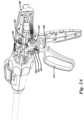
- FIG. 2A is a schematic diagram of a surgical handle assembly in a first mode and in a first movable handle member position (e.g., "ready" position) in accordance with a number of embodiments of the present disclosure.
- the surgical handle apparatus 206 can include a movable handle member 210, a switch 220, and a driving pawl 230.
- the switch 220 can provide two or more modes of operation for the movable handle member 210.
- the driving pawl 230 in a number of embodiments can be pivotally connected to a swing wheel 226 and can be configured to advance an actuation shaft 240 linearly in a distal direction in response to actuation of the movable handle member 210.
- the surgical handle assembly 206 can be in a first mode, as shown in Figure 2A .
- the surgical handle assembly 206, in a first mode can have a first distance (e.g. distance 513 in Fig. 5 ) between a pivot point around first pin 222 to a coupling pin 232 of the driving pawl 230.
- the surgical handle assembly 206, in a second mode can have a second distance (e.g. distance 515 in Fig. 5 ) between a pivot point around second pin 224 to the coupling pin 232 of the driving pawl 230.
- the second distance e.g. distance 515 in Fig. 5
- a number of pivot points can exist and a pivot point can be around a pin placed in an opening in the movable handle 210.
- a first pin 222 in the first mode, can be coupled to the movable handle member 210 in a first opening and a second pin 224 can be disengaged from the second opening (e.g. second opening 454 in Fig. 4 ) so as not to be coupled to the movable handle member 210.
- the first pin 222 can serve as the pivot point for the movable handle member 210 with the first distance (e.g. distance 513 in Fig. 5 ) between the pivot point and coupling pin 232.
- a second pin 224 can be coupled to the movable handle member 210.
- the first pin 222 can be disengaged from the first opening (e.g. first opening 452 in Fig. 4 ) so as not to be coupled to the movable handle member 210.
- the second pin 224 can serve as the pivot point for the movable handle member 210.
- the second distance e.g. distance 515 in Fig. 5
- the first distance e.g. first distance 513 in Fig. 5 ).
- an amount of force used to advance the actuation shaft 240 linearly in a distal direction is less than an amount of force used to advance the actuation shaft 240 linearly in the distal direction in a second mode of operation, using the second pin 224 as the pivot point.
- the amount of force used is less in the first mode than in the second mode due to the distance between the pivot point and the coupling pin 232 of the driving pawl 230 and because the travel distance is less.
- the surgical handle assembly 206 can be in a first mode. In a first mode, the surgical handle assembly 206 can operate to advance the actuation shaft 240 a third distance (e.g. distance 544 in Fig. 5 ). The third distance (e.g. distance 544 in Fig. 5 ) is a length of advance of the actuation shaft 240 in a distal direction, upon actuation of the movable handle member 210 in the first mode.
- the surgical handle assembly 206 can alternatively be changed to a second mode of operation. In a second mode, the surgical handle assembly 206 can operate to advance the actuation shaft 240 a fourth distance (e.g. distance 546 in Fig. 5 ). The fourth distance (e.g.).
- distance 546 in Fig. 5 is a length of advance of the actuation shaft 240 in the distal direction upon actuation of the movable handle member 210 in the second mode.
- the fourth distance e.g. distance 546 in Fig. 5
- the third distance e.g. third distance 544 in Fig. 5 ).
- the surgical handle assembly 206 can be in a ready position, as shown in Figure 2A .
- the surgical handle assembly 206 is ready to advance the actuation shaft 240 linearly in a distal direction upon actuation of the movable handle member 210.
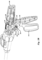
- FIG. 2B is a schematic diagram of a surgical handle assembly in a first mode and a second movable handle member position (e.g. a "compressed” and/or “closed” position) in accordance with a number of embodiments of the present disclosure.
- the surgical handle assembly 206 can include a movable handle member 210, a switch 220, and a driving pawl 230.
- the switch 220 can provide two or more modes of operation for the movable handle member 210.
- the driving pawl 230 in a number of embodiments can be pivotally connected to a swing wheel 226 and can be configured to advance an actuation shaft 240 linearly in a distal direction in response to actuation of the movable handle member 210.
- the surgical handle assembly 206 can be in a first mode, as shown in Figure 2B .
- the surgical handle assembly 206, in a first mode can have a first distance (e.g. distance 513 in Fig. 5 ) between the pivot point around first pin 222 to a coupling pin 232 of the driving pawl 230.
- the surgical handle assembly 206, in a second mode can have a second distance (e.g. distance 515 in Fig. 5 ) from the pivot point around second pin 224 to the coupling pin 232 of the driving pawl 230.
- the second distance e.g. distance 515 in Fig. 5
- the first distance e.g. distance 513 in Fig. 5 .
- a number of pivot points can exist and a pivot point can be around a pin placed in an opening in the movable handle 210.
- the first pin 222 in the first mode, can be coupled to the movable handle member 210 in a first opening (e.g. first opening 452 in Fig. 4 ) and the second pin 224 can be disengaged from a second opening (e.g. second opening 454 in Fig. 4 ) so as not to be coupled to the movable handle member 2010.
- the first pin 222 can serve as the pivot point for the movable handle member 210 with the first distance (e.g. distance 513 in Fig. 5 ) between the pivot point and coupling pin 232.
- the second pin 224 can serve as the pivot point for the movable handle member 210.
- the second distance e.g. distance 515 in Fig. 5
- the first distance e.g. distance 513 in Fig. 5
- an amount of force used to advance the actuation shaft 240 linearly in a distal direction is less than an amount of force used to advance the actuation shaft linearly in the distal direction in a second mode of operation, using the second pin 224 as the pivot point.
- the amount of force is less in the first mode than in the second mode due to the distance between the pivot point and the coupling pin 232 of the driving pawl 230 and the travel distance is less.
- the surgical handle assembly 206 can operate to advance the actuation shaft 240 a third distance (e.g. third distance 544 in Fig. 5 ).
- the third distance (e.g. distance 544 in Fig. 5 ) is a length of advance of the actuation shaft 240 in a distal direction, upon actuation of the movable handle member 210.
- the surgical handle assembly 206 can be in a second mode.
- the surgical handle assembly 206 can operate to advance the actuation shaft 240 a fourth distance (e.g. distance 546 in Fig. 5 ).
- the fourth distance (e.g. distance 546 in Fig. 5 ) is a length of advance of the actuation shaft 240 in the distal direction.
- the fourth distance (e.g. distance 546 in Fig. 5 ) is longer than the third distance (e.g. distance 544 in Fig. 5 ).
- the fourth distance can be twice as long as the third distance.
- the actuation shaft 240 can be advanced twice as far in the second mode than in the first mode
- the surgical handle assembly 206 can be in a closed position, as shown in Figure 2B . As will be explained more in connection with Figure 4 . In a closed position, the surgical handle assembly 206 can prevent the actuation shaft 240 from moving linearly in a distal and/or proximal direction upon release of the movable handle member 210 by having the driving pawl 230 disengage from teeth of a ratchet associated with the actuation shaft 240 and reengage with teeth further back at a starting point of the ratchet.
- the pivot point of the surgical handle assembly 206 can be changed using the switch 220.
- the switch 220 when actuated, can rotate a gear 223.
- the gear 223 can contact one or more gears of the first pin 222 and one or more gears of the second pin 224.
- the surgical handle assembly 206 can be placed in the first mode when the switch 220 is actuated in a first direction.
- the gear 223 can rotate in a first rotational direction.
- the gear 223 can insert the first pin 222 into a first opening (e.g. first opening 452 in Fig.
- the surgical handle assembly 206 can be placed in the second mode when the switch 220 is actuated in a second direction.
- the gear can rotate in a second rotational direction.
- the gear 223 can insert the second pin 224 into a second opening (e.g. second opening 454 in Fig. 4 ) and can remove the first pin 222 from the first opening (e.g. first opening 452 in Fig. 4 ).
- This example is used throughout the present disclosure for ease of understanding and illustration.
- Embodiments are not limited to a gear (e.g., gear 223 in Figure 2A , for example) to transition between modes of operation.
- a number of mechanisms e.g. a switch
- a push pin can be used to switch the surgical handle assembly 206 from one mode to another.
- a switch can be coupled to a first pin and a second pin such that when the first pin is pushed into the first opening (e.g. first opening 452 in Fig. 4 ) the second pin is removed from the second opening (e.g.
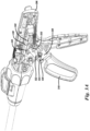
- FIG 3A is a schematic diagram of a surgical handle assembly in a second mode and a first movable handle position (e.g., "ready" position) in accordance with a number of embodiments of the present disclosure.
- the surgical handle assembly 306 can include a movable handle member 310, a switch 320, and a driving pawl 330.
- the switch 320 can provide two or more modes of operation for the movable handle member 310.
- the driving pawl 330 in a number of embodiments can be pivotally connected to the swing wheel 326 and can be configured to advance an actuation shaft 340 linearly in a distal direction in response to actuation of the movable handle member 310.
- the surgical handle assembly 306 can be in a second mode, as shown in Figure 3A .
- the surgical handle assembly 306, in a second mode can have a second distance (e.g. distance 515 in Fig. 5 ) between the pivot point around a second pin 324 to the coupling pin 332 of the driving pawl 330.
- the second distance is longer than the first distance (e.g. distance 513 in Fig. 5 ).
- a number of pivot points can exist and a pivot point can be around a pin placed in an opening in the movable handle 310.
- a second pin 324 can be coupled to the movable handle member 310.
- the first pin 322 can be disengaged from the first opening (e.g. first opening 452 in Fig. 4 ) so as not to be coupled to the movable handle member 310.
- the second pin 324 can serve as the pivot point for the movable handle member 310.
- the driving pawl 330 is configured to contact a toothed rack 342 of the actuation shaft 340 to advance the actuation shaft linearly in a distal direction.
- the actuation shaft 340 can be advanced in response to actuation of the movable handle member 310.
- the second distance e.g. distance 515 in Fig. 5
- the first distance e.g.
- the second mode operation advances twice as many ratchets of the toothed rack 342 than the first mode of operation.
- twice as many ratchets are advanced in the second mode due to the distance between the pivot point and the coupling pin 332 of the driving pawl 330.
- a swing wheel 326 is connected to the movable handle member 310.
- the movable handle member can include a coupling opening (e.g. coupling opening 516 in Fig. 5 ).
- the swing wheel 326 and the coupling opening can be used in the second mode of operation to allow transfer of force from the movable handle member 310 to the driving pawl 330. Transferring the force from the movable handle member 310 to the driving pawl 330 allows the actuation shaft 340 to advance linearly in the distal direction.
- the surgical handle assembly 306 can be in a ready position, as shown in Figure 3A .
- the ready position the surgical handle assembly 306 is ready to advance the actuation shaft 340 linearly in a distal direction upon actuation of the movable handle member 310.
- FIG. 3B is a schematic diagram of a surgical handle assembly in a second mode and a second movable handle member position (e.g. a "compressed” and/or “closed” position) in accordance with a number of embodiments of the present disclosure.
- the surgical handle assembly 306 can include a movable handle member 310, a switch 320, and a driving pawl 330.
- the switch 320 can provide two or more modes of operation for the movable handle member 310.
- the driving pawl 330 in a number of embodiments can be pivotally connected to the swing wheel 326 and can be configured to advance an actuation shaft 340 linearly in a distal direction in response to actuation of the movable handle member 310.
- the surgical handle assembly 306 can be in a second mode, as shown in Figure 3B .
- the surgical handle assembly 306, in the second mode can have a second distance (e.g. second distance 515 in Fig. 5 ) from the pivot point around the second pin 324 to the coupling pin 332 of the driving pawl 330.
- the second distance e.g. distance 515 in Fig. 5
- the first distance e.g. first distance 513 in Fig. 5
- a number of pivot points can exist and a pivot point can be around a pin placed in an opening in the movable handle 310.
- a second pin 324 can be coupled to the movable handle member 310.
- the first pin 322 can be disengaged from the first opening (e.g. first opening 452 in Fig. 4 ) so as not to be coupled to the movable handle member 310.
- the second pin 324 can serve as the pivot point for the movable handle member 310.
- the second pin 324 can serve as the pivot point for the movable handle member 310.
- the second distance e.g. distance 515 in Fig. 5
- the first distance e.g. distance 513 in Fig. 5 ).
- the driving pawl 330 is configured to contact a toothed rack 342 of an actuation shaft 340 to advance the actuation shaft linearly in a distal direction in response to actuation of the movable handle member 310.
- the second distance e.g. distance 515 in Fig. 5
- the first distance e.g. first distance 513 in Fig. 5
- the second mode of operation advances the actuation shaft 340 twice as far and advances twice as many ratchets of the toothed rack than the first mode of operation.
- the actuation shaft 340 is advanced twice as far and twice as many ratchets are advanced in the second mode due to the distance between the pivot point and the coupling pin 332 of the driving pawl 330.
- the surgical handle assembly 306 can be in a closed position, as shown in Figure 3B . In a closed position, the surgical handle assembly 306 can prevent the actuation shaft 340 from moving linearly in a distal and/or proximal direction upon release of the movable handle member 310.
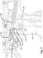
- Figure 4 is a schematic diagram of a surgical handle assembly including a first opening, a second opening, and a slot in accordance with a number of embodiments of the present disclosure.
- the movable handle member 410 can include a first opening 452 and a second opening 454.
- the first pin e.g. first pin 222 in Fig. 2A
- the second pin e.g. second pin 224 in Fig. 2A
- the swing wheel 426 can include a slot 428.
- the slot 428 can allow the swing wheel 426 to rotate whether the first pin (e.g. first pin 222 in Fig. 2A ) is inserted into the first opening 452 or the first pin (e.g. first pin 222 in Fig. 2A ) is removed from the first opening 452.
- Figure 5 is a schematic diagram of a surgical handle assembly including a coupling opening 516 in accordance with a number of embodiments of the present disclosure.
- the movable handle member 510 can include a coupling opening 516.
- the coupling pin e.g. coupling pin 232 in Fig. 2A
- the coupling opening 516 can allow the actuation shaft 540 to advance linearly in the distal direction without coupling pin 232 binding due to the shape of the coupling opening 516.
- the coupling opening 516 shape for example, can be a "U" shape, e.g. saddle, allowing degrees of translation and movement in contrast to being a fixed point.
- the surgical handle assembly 506 can be in a first mode.
- the first pin e.g. first pin 222 in Fig. 2A
- the second pin e.g. second pin 224 in Fig. 2A
- the second distance 515 is longer than the first distance 513.
- the surgical handle assembly 506 can be in a first mode having a third distance 544.
- the third distance 544 is a length of advance of the actuation shaft 540 in the distal direction.
- the surgical handle assembly 506 can be in a second mode having a fourth distance 546.
- the fourth distance 546 is a length of advance of the actuation shaft 540 in the distal direction. In this example, the fourth distance 546 is longer than the third distance 544.
- Figure 5 illustrates the surgical handle assembly 506 in a second mode and the movable handle member 510 in a closed position.
- the driving pawl e.g. driving pawl 230 in Fig. 2A
- the driving pawl in this example, is at the end of the fourth distance 546 and has fully advanced the actuation shaft 540 for an actuation of the movable handle member 510 in the second mode of operation.
- the driving pawl e.g. driving pawl 230 in Fig. 2A
- the driving pawl can be at the end of the third distance 544 and has fully advanced the actuation shaft 540 for an actuation of the movable handle member 510 in the first mode of operation.
Landscapes
- Health & Medical Sciences (AREA)
- Life Sciences & Earth Sciences (AREA)
- Surgery (AREA)
- Heart & Thoracic Surgery (AREA)
- Engineering & Computer Science (AREA)
- Biomedical Technology (AREA)
- Nuclear Medicine, Radiotherapy & Molecular Imaging (AREA)
- Medical Informatics (AREA)
- Molecular Biology (AREA)
- Animal Behavior & Ethology (AREA)
- General Health & Medical Sciences (AREA)
- Public Health (AREA)
- Veterinary Medicine (AREA)
- Surgical Instruments (AREA)
Description
- The present disclosure relates generally to a surgical handle assembly, and more particularly, to a surgical handle assembly configured to provide two or more modes of operation.
- A surgical handle assembly can be used in a number of surgical devices. One example includes use as a surgical stapler. A surgical stapler is a fastening device used to clamp tissue between opposing jaw structures to join tissue using surgical fasteners. Surgical staplers can include two elongated members used to clamp the tissue. One of the elongated members can include one or more reloadable cartridges and the other elongated member can include an anvil that can be used to form a staple when driven from the reloadable cartridge. A surgical stapler can receive one or more reloadable cartridges. An example of reloadable cartridges can include having rows of staples having a linear length. For example, a row of staples can have a linear length between 30mm and 60mm. A staple can be ejected by actuation of a movable handle member that is a part of the surgical handle assembly of the surgical stapler.
-
US 2011/0290854 A1 discloses a surgical instrument including an end effector that has a selectively reciprocatable implement movably supported therein.EP 2839786 A1 discloses a motor-driven surgical instrument including a surgical end effector configured to perform at least one surgical procedure in response to firing motions applied thereto from a firing system, an articulation system configured to facilitate articulation of the end effector relative to an elongated tool axis, and a coupler assembly configured to enable the motor to selectively power the firing system and the articulation system. -
-
Figure 1 is a schematic diagram of a surgical stapling apparatus including a surgical handle assembly in accordance with a number of embodiments of the present disclosure. -
Figure 2A is a schematic diagram of a surgical handle assembly in a first mode and a first movable handle member position in accordance with a number of embodiments of the present disclosure. -
Figure 2B is a schematic diagram of a surgical handle assembly in a first mode and a second movable handle member position in accordance with a number of embodiments of the present disclosure. -
Figure 3A is a schematic diagram of a surgical handle assembly in a second mode and a first movable handle member position in accordance with a number of embodiments of the present disclosure. -
Figure 3B is a schematic diagram of a surgical handle assembly in a second mode and a second movable handle member position in accordance with a number of embodiments of the present disclosure. -
Figure 4 is a schematic diagram of a surgical handle assembly including a first opening, a second opening, and a slot in accordance with a number of embodiments of the present disclosure. -
Figure 5 is a schematic diagram of a surgical handle assembly including a coupling point opening in accordance with a number of embodiments of the present disclosure. - The invention is defined in independent claim 1. Optional features of the invention are defined in the dependent claims. The present disclosure includes apparatuses for a surgical handle assembly. According to a first aspect, a surgical handle assembly apparatus is provided, comprising: a movable handle member; a switch configured to: provide a first mode of operation and a second mode of operation for the movable handle member, wherein the first mode of operation deploys one or more staples and the second mode of operation deploys one or more staples, and wherein the first mode of operation deploys a different number of staples than the second mode of operation; and a driving pawl pivotally connected to a swing wheel, wherein the driving pawl is configured to: advance an actuation shaft linearly in a distal direction a first distance in response to actuation of the movable handle member in the first mode of operation and advance the actuation shaft linearly in the distal direction a second distance in response to actuation of the movable handle member in the second mode of operation. The switch is configured to switch between the movable handle member being coupled to a first pin and a second pin so as to change a distance between the one of the first pin and second pin serving as pivot point for the movable handle member and a coupling pin of the driving pawl
- In a number of embodiments, the mode selection capability can be a switch. The surgical handle assembly is described with the switch example throughout the present disclosure for ease of understanding and illustration; however embodiments are not limited to a switch. For example, the switch can include a first pin and a second pin to set modes of operation. While a first pin and a second pin are shown by example, more than two pins and/or two modes of operation are included in the embodiments disclosed herein. In this example, the first pin when set to a particular position can provide a first mode of operation for the movable handle member. The second pin when set to a particular position can provide a second mode of operation for the movable handle member. Use of the surgical handle assembly with a surgical stapler in the first mode of operation can advance an actuation shaft a first distance in the distal direction and coupled to a reloadable cartridge can deploy a first number of staples. Use of the surgical handle assembly with a surgical stapler in the second mode of operation can advance an actuation shaft a second distance in a distal direction and coupled to a reloadable cartridge can deploy a second, different number of staples. In a number of embodiments, the first mode of operation or the second mode of operation can be selected based on the type of tissue being fastened, a number of staples to be deployed, speed of staples being deployed, and/or an amount of force to be applied by a user to actuate the movable handle member, for example. A mode of operation can be selected based on the type of tissue being fastened, for example, when the tissue is thick, the user may use a mode that requires less force to be applied. A mode that requires less force also may be used when the user is fatigued or physically unable to use a mode that requires more force, for example. A mode of operation can be selected based on speed of staples being deployed to lower edema, e.g. less blood in area being stapled, to allow stapling of tissue rather than blood.
- In a number of embodiments, the movable handle member may be coupled to a swing wheel. In this manner, the movable handle member and swing wheel may pivot around the first pin at a first pivot point during a first mode. The first pin can be connected to the movable handle member via a first opening in the swing wheel and movable handle member to engage the movable handle member. In a number of embodiments, the movable handle member and swing wheel may pivot around the second pin at a second pivot point during a second mode. The second pin can be connected to the movable handle member via a second opening in the swing wheel and movable handle member to engage the movable handle member. The second pin is not coupled to the movable handle member via the second opening while in the first mode of operation. The first pin is not coupled to the movable handle member via the first opening while in the second mode of operation.
- In a number of embodiments, transition from the first mode of operation to the second mode of operation can be accomplished by removing the first pin from the first opening while engaging the second pin with the second opening. The switch may be moved from a first position to a second position in order to engage and/or disengage the first and second pins with their respective openings. Transition from the second mode of operation to the first mode of operation can be accomplished by removing the second pin from the second opening while engaging the first pin with the first opening. Here, the switch may be moved from a second position to a first position to engage and/or disengage the first and second pins with their respective openings.
- In the following detailed description of the present disclosure, reference is made to the accompanying drawings that form a part hereof, and in which is shown by way of illustration how one or more embodiments of the disclosure may be practiced. These embodiments are described in sufficient detail to enable those of ordinary skill in the art to practice the embodiments of this disclosure, and it is to be understood that other embodiments may be utilized and that process, electrical, and structural changes may be made without departing from the scope of the present disclosure.
- As used herein, designators such as "X", "Y", "N", "M", etc., particularly with respect to reference numerals in the drawings, indicate that a number of the particular feature so designated can be included. It is also to be understood that the terminology used herein is for the purpose of describing particular embodiments only, and is not intended to be limiting. As used herein, the singular forms "a", "an", and "the" can include both singular and plural referents, unless the context clearly dictates otherwise. In addition, "a number of", "at least one", and "one or more" (e.g., a number of pivot points) can refer to one or more pivot points, whereas a "plurality of" is intended to refer to more than one of such things. Furthermore, the words "can" and "may" are used throughout this application in a permissive sense (i.e., having the potential to, being able to), not in a mandatory sense (i.e., must). The term "include," and derivations thereof, means "including, but not limited to". The terms "coupled" and "coupling" mean to be directly or indirectly connected physically or for access to and movement of the movable handle member, as appropriate to the context.
- The figures herein follow a numbering convention in which the first digit or digits correspond to the figure number and the remaining digits identify an element or component in the figure. Similar elements or components between different figures may be identified by the use of similar digits. For example, 210 may reference element "10" in
Figure 2A , and a similar element may be referenced as 310 inFigure 3A . As will be appreciated, elements shown in the various embodiments herein can be added, exchanged, and/or eliminated so as to provide a number of additional embodiments of the present disclosure. In addition, the proportion and/or the relative scale of the elements provided in the figures are intended to illustrate certain embodiments of the present disclosure and should not be taken in a limiting sense. -
Figure 1 is a schematic diagram of asurgical stapling apparatus 102 including asurgical handle assembly 106 in accordance with a number of embodiments of the present disclosure. In the example, asurgical stapler apparatus 102 can include asurgical handle assembly 106 and areloadable cartridge assembly 103. As shown in the example ofFigure 1 , thereloadable cartridge assembly 103, e.g. a disposable loading unit, can be releasably secured to a distal end of an elongated body of thesurgical handle assembly 106. In this example, thereloadable cartridge assembly 103 can include a firstelongated member 104 and a secondelongated member 105 that can be used to clamp tissue. One of the elongated members can house one or more staple cartridges. The other elongated member can have an anvil that can be used to form a staple when driven from the staple cartridge. As mentioned, asurgical stapling apparatus 102 can receive reloadable cartridge assemblies having rows of staples. In a number of embodiments, third party reloadable cartridge and/or reloadable cartridge assemblies may be used with thesurgical handle assembly 106 and embodiments ofsurgical handle assembly 106 may be configured to receive the same. A staple can be ejected by actuation of amovable handle member 110 that is a part of asurgical handle assembly 106 to thesurgical stapling apparatus 102. Actuation of themovable handle member 110 can actuate the actuation shaft (e.g. actuation shaft 240 inFig. 2A ) to eject a number of staples. For example, in a first mode of operation, actuation of themovable handle member 110 may eject 30 staples. In a second mode, actuation of themovable handle member 110 may eject 60 staples. However, embodiments are not limited to a particular number of staples ejected in the first or second mode. Further, embodiments are not limited to use with a surgical stapling apparatus. Thesurgical handle assembly 106 is described with thesurgical stapling apparatus 102 example throughout the present disclosure for ease of understanding and illustration. -
Figure 2A is a schematic diagram of a surgical handle assembly in a first mode and in a first movable handle member position (e.g., "ready" position) in accordance with a number of embodiments of the present disclosure. Thesurgical handle apparatus 206 can include amovable handle member 210, aswitch 220, and a drivingpawl 230. Theswitch 220 can provide two or more modes of operation for themovable handle member 210. The drivingpawl 230 in a number of embodiments can be pivotally connected to aswing wheel 226 and can be configured to advance anactuation shaft 240 linearly in a distal direction in response to actuation of themovable handle member 210. - In a number of embodiments, the
surgical handle assembly 206 can be in a first mode, as shown inFigure 2A . Thesurgical handle assembly 206, in a first mode, can have a first distance (e.g. distance 513 inFig. 5 ) between a pivot point aroundfirst pin 222 to acoupling pin 232 of the drivingpawl 230. Thesurgical handle assembly 206, in a second mode, can have a second distance (e.g. distance 515 inFig. 5 ) between a pivot point aroundsecond pin 224 to thecoupling pin 232 of the drivingpawl 230. In this example, the second distance (e.g. distance 515 inFig. 5 ) is longer than the first distance (e.g.first distance 513 inFig. 5 ). In a number of embodiments, a number of pivot points can exist and a pivot point can be around a pin placed in an opening in themovable handle 210. InFigure 2A , in the first mode, afirst pin 222 can be coupled to themovable handle member 210 in a first opening and asecond pin 224 can be disengaged from the second opening (e.g.second opening 454 inFig. 4 ) so as not to be coupled to themovable handle member 210. In the first mode thefirst pin 222 can serve as the pivot point for themovable handle member 210 with the first distance (e.g. distance 513 inFig. 5 ) between the pivot point andcoupling pin 232. In a second mode, asecond pin 224 can be coupled to themovable handle member 210. In this example, thefirst pin 222 can be disengaged from the first opening (e.g.first opening 452 inFig. 4 ) so as not to be coupled to themovable handle member 210. In the second mode thesecond pin 224 can serve as the pivot point for themovable handle member 210. In this example, the second distance (e.g. distance 515 inFig. 5 ) is longer than the first distance (e.g.first distance 513 inFig. 5 ). As such, in the first mode, when thefirst pin 222 is the pivot point, an amount of force used to advance theactuation shaft 240 linearly in a distal direction is less than an amount of force used to advance theactuation shaft 240 linearly in the distal direction in a second mode of operation, using thesecond pin 224 as the pivot point. In this example, the amount of force used is less in the first mode than in the second mode due to the distance between the pivot point and thecoupling pin 232 of the drivingpawl 230 and because the travel distance is less. - In a number of embodiments, the
surgical handle assembly 206 can be in a first mode. In a first mode, thesurgical handle assembly 206 can operate to advance the actuation shaft 240 a third distance (e.g. distance 544 inFig. 5 ). The third distance (e.g. distance 544 inFig. 5 ) is a length of advance of theactuation shaft 240 in a distal direction, upon actuation of themovable handle member 210 in the first mode. Thesurgical handle assembly 206 can alternatively be changed to a second mode of operation. In a second mode, thesurgical handle assembly 206 can operate to advance the actuation shaft 240 a fourth distance (e.g. distance 546 inFig. 5 ). The fourth distance (e.g. distance 546 inFig. 5 ) is a length of advance of theactuation shaft 240 in the distal direction upon actuation of themovable handle member 210 in the second mode. In this example, the fourth distance (e.g. distance 546 inFig. 5 ) is longer than the third distance (e.g.third distance 544 inFig. 5 ). - In a number of embodiments, the
surgical handle assembly 206 can be in a ready position, as shown inFigure 2A . In the ready position, thesurgical handle assembly 206 is ready to advance theactuation shaft 240 linearly in a distal direction upon actuation of themovable handle member 210. -
Figure 2B is a schematic diagram of a surgical handle assembly in a first mode and a second movable handle member position (e.g. a "compressed" and/or "closed" position) in accordance with a number of embodiments of the present disclosure. Thesurgical handle assembly 206 can include amovable handle member 210, aswitch 220, and a drivingpawl 230. Theswitch 220 can provide two or more modes of operation for themovable handle member 210. The drivingpawl 230 in a number of embodiments can be pivotally connected to aswing wheel 226 and can be configured to advance anactuation shaft 240 linearly in a distal direction in response to actuation of themovable handle member 210. - In a number of embodiments, the
surgical handle assembly 206 can be in a first mode, as shown inFigure 2B . Thesurgical handle assembly 206, in a first mode, can have a first distance (e.g. distance 513 inFig. 5 ) between the pivot point aroundfirst pin 222 to acoupling pin 232 of the drivingpawl 230. Thesurgical handle assembly 206, in a second mode, can have a second distance (e.g. distance 515 inFig. 5 ) from the pivot point aroundsecond pin 224 to thecoupling pin 232 of the drivingpawl 230. In this example, the second distance (e.g. distance 515 inFig. 5 ) is longer than the first distance (e.g. distance 513 inFig. 5 ). In a number of embodiments, a number of pivot points can exist and a pivot point can be around a pin placed in an opening in themovable handle 210. InFigure 2B , in the first mode, thefirst pin 222 can be coupled to themovable handle member 210 in a first opening (e.g.first opening 452 inFig. 4 ) and thesecond pin 224 can be disengaged from a second opening (e.g.second opening 454 inFig. 4 ) so as not to be coupled to the movable handle member 2010. In the first mode, thefirst pin 222 can serve as the pivot point for themovable handle member 210 with the first distance (e.g. distance 513 inFig. 5 ) between the pivot point andcoupling pin 232. In the second mode thesecond pin 224 can serve as the pivot point for themovable handle member 210. In this example, the second distance (e.g. distance 515 inFig. 5 ) is longer than the first distance (e.g. distance 513 inFig. 5 ). Again, in the first mode, when thefirst pin 222 is the pivot point, an amount of force used to advance theactuation shaft 240 linearly in a distal direction is less than an amount of force used to advance the actuation shaft linearly in the distal direction in a second mode of operation, using thesecond pin 224 as the pivot point. In this example, the amount of force is less in the first mode than in the second mode due to the distance between the pivot point and thecoupling pin 232 of the drivingpawl 230 and the travel distance is less. - In a first mode, the
surgical handle assembly 206 can operate to advance the actuation shaft 240 a third distance (e.g.third distance 544 inFig. 5 ). The third distance (e.g. distance 544 inFig. 5 ) is a length of advance of theactuation shaft 240 in a distal direction, upon actuation of themovable handle member 210. Thesurgical handle assembly 206 can be in a second mode. In a second mode, thesurgical handle assembly 206 can operate to advance the actuation shaft 240 a fourth distance (e.g. distance 546 inFig. 5 ). The fourth distance (e.g. distance 546 inFig. 5 ) is a length of advance of theactuation shaft 240 in the distal direction. In this example, the fourth distance (e.g. distance 546 inFig. 5 ) is longer than the third distance (e.g. distance 544 inFig. 5 ). In a number of embodiments the fourth distance can be twice as long as the third distance. As such, theactuation shaft 240 can be advanced twice as far in the second mode than in the first mode - In a number of embodiments, the
surgical handle assembly 206 can be in a closed position, as shown inFigure 2B . As will be explained more in connection withFigure 4 . In a closed position, thesurgical handle assembly 206 can prevent theactuation shaft 240 from moving linearly in a distal and/or proximal direction upon release of themovable handle member 210 by having the drivingpawl 230 disengage from teeth of a ratchet associated with theactuation shaft 240 and reengage with teeth further back at a starting point of the ratchet. - In a number of embodiments, the pivot point of the
surgical handle assembly 206 can be changed using theswitch 220. In an example, theswitch 220, when actuated, can rotate agear 223. Thegear 223 can contact one or more gears of thefirst pin 222 and one or more gears of thesecond pin 224. Thesurgical handle assembly 206 can be placed in the first mode when theswitch 220 is actuated in a first direction. When theswitch 220 is actuated in the first direction, thegear 223 can rotate in a first rotational direction. When thegear 223 is rotated in a first rotational direction thegear 223 can insert thefirst pin 222 into a first opening (e.g.first opening 452 inFig. 4 ) and can remove thesecond pin 224 from a second opening (e.g.second opening 454 inFig. 4 ). Thesurgical handle assembly 206 can be placed in the second mode when theswitch 220 is actuated in a second direction. When theswitch 220 is actuated in the second direction the gear can rotate in a second rotational direction. When thegear 223 is rotated in a second rotational direction the gear 223can insert thesecond pin 224 into a second opening (e.g.second opening 454 inFig. 4 ) and can remove thefirst pin 222 from the first opening (e.g.first opening 452 inFig. 4 ). This example is used throughout the present disclosure for ease of understanding and illustration. Embodiments are not limited to a gear (e.g.,gear 223 inFigure 2A , for example) to transition between modes of operation. A number of mechanisms (e.g. a switch) to insert and remove a number of pins in a number of openings in a moveable handle member for operation in a number of modes can be used in accordance with a number of embodiments of the present disclosure to transition between modes of operation. For example, a push pin can be used to switch thesurgical handle assembly 206 from one mode to another. A switch can be coupled to a first pin and a second pin such that when the first pin is pushed into the first opening (e.g.first opening 452 inFig. 4 ) the second pin is removed from the second opening (e.g.second opening 454 inFig. 4 ). As well as when the second pin is pushed into the second opening (e.g.second opening 454 inFig. 4 ) the first pin is removed from the first opening (e.g.first opening 452 inFig. 4 ). -
Figure 3A is a schematic diagram of a surgical handle assembly in a second mode and a first movable handle position (e.g., "ready" position) in accordance with a number of embodiments of the present disclosure. Thesurgical handle assembly 306 can include amovable handle member 310, aswitch 320, and a drivingpawl 330. Theswitch 320 can provide two or more modes of operation for themovable handle member 310. The drivingpawl 330 in a number of embodiments can be pivotally connected to theswing wheel 326 and can be configured to advance anactuation shaft 340 linearly in a distal direction in response to actuation of themovable handle member 310. - In a number of embodiments, the
surgical handle assembly 306 can be in a second mode, as shown inFigure 3A . Thesurgical handle assembly 306, in a second mode, can have a second distance (e.g. distance 515 inFig. 5 ) between the pivot point around asecond pin 324 to thecoupling pin 332 of the drivingpawl 330. In this example, the second distance is longer than the first distance (e.g. distance 513 inFig. 5 ). In a number of embodiments a number of pivot points can exist and a pivot point can be around a pin placed in an opening in themovable handle 310. InFigure 3A , in a second mode, asecond pin 324 can be coupled to themovable handle member 310. In this example, thefirst pin 322 can be disengaged from the first opening (e.g.first opening 452 inFig. 4 ) so as not to be coupled to themovable handle member 310. In the second mode thesecond pin 324 can serve as the pivot point for themovable handle member 310. In a number of embodiments, the drivingpawl 330 is configured to contact atoothed rack 342 of theactuation shaft 340 to advance the actuation shaft linearly in a distal direction. Theactuation shaft 340 can be advanced in response to actuation of themovable handle member 310. In this example, the second distance (e.g. distance 515 inFig. 5 ) is longer than the first distance (e.g.first distance 513 inFig. 5 ). As such, when thesecond pin 324 is the pivot point, the second mode operation advances twice as many ratchets of thetoothed rack 342 than the first mode of operation. In this example, twice as many ratchets are advanced in the second mode due to the distance between the pivot point and thecoupling pin 332 of the drivingpawl 330. - In a number of embodiments, a
swing wheel 326 is connected to themovable handle member 310. Also, in a number of embodiments, the movable handle member can include a coupling opening (e.g. coupling opening 516 inFig. 5 ). Theswing wheel 326 and the coupling opening (e.g. coupling opening 516 inFig. 5 ) can be used in the second mode of operation to allow transfer of force from themovable handle member 310 to the drivingpawl 330. Transferring the force from themovable handle member 310 to the drivingpawl 330 allows theactuation shaft 340 to advance linearly in the distal direction. - In a number of embodiments, the
surgical handle assembly 306 can be in a ready position, as shown inFigure 3A . In the ready position thesurgical handle assembly 306 is ready to advance theactuation shaft 340 linearly in a distal direction upon actuation of themovable handle member 310. -
Figure 3B is a schematic diagram of a surgical handle assembly in a second mode and a second movable handle member position (e.g. a "compressed" and/or "closed" position) in accordance with a number of embodiments of the present disclosure. Thesurgical handle assembly 306 can include amovable handle member 310, aswitch 320, and a drivingpawl 330. Theswitch 320 can provide two or more modes of operation for themovable handle member 310. The drivingpawl 330 in a number of embodiments can be pivotally connected to theswing wheel 326 and can be configured to advance anactuation shaft 340 linearly in a distal direction in response to actuation of themovable handle member 310. - In a number of embodiments, the
surgical handle assembly 306 can be in a second mode, as shown inFigure 3B . Thesurgical handle assembly 306, in the second mode, can have a second distance (e.g.second distance 515 inFig. 5 ) from the pivot point around thesecond pin 324 to thecoupling pin 332 of the drivingpawl 330. In this example, the second distance (e.g. distance 515 inFig. 5 ) is longer than the first distance (e.g.first distance 513 inFig. 5 ). In a number of embodiments a number of pivot points can exist and a pivot point can be around a pin placed in an opening in themovable handle 310. In a second mode, asecond pin 324 can be coupled to themovable handle member 310. In this example, thefirst pin 322 can be disengaged from the first opening (e.g.first opening 452 inFig. 4 ) so as not to be coupled to themovable handle member 310. In the second mode thesecond pin 324 can serve as the pivot point for themovable handle member 310. In the second mode thesecond pin 324 can serve as the pivot point for themovable handle member 310. In this example, the second distance (e.g. distance 515 inFig. 5 ) is longer than the first distance (e.g. distance 513 inFig. 5 ). In a number of embodiments, the drivingpawl 330 is configured to contact atoothed rack 342 of anactuation shaft 340 to advance the actuation shaft linearly in a distal direction in response to actuation of themovable handle member 310. In this example, the second distance (e.g. distance 515 inFig. 5 ) is longer than the first distance (e.g.first distance 513 inFig. 5 ). As such, when thesecond pin 324 serves as the pivot point, the second mode of operation advances theactuation shaft 340 twice as far and advances twice as many ratchets of the toothed rack than the first mode of operation. In this example, theactuation shaft 340 is advanced twice as far and twice as many ratchets are advanced in the second mode due to the distance between the pivot point and thecoupling pin 332 of the drivingpawl 330. - In a number of embodiments, the
surgical handle assembly 306 can be in a closed position, as shown inFigure 3B . In a closed position, thesurgical handle assembly 306 can prevent theactuation shaft 340 from moving linearly in a distal and/or proximal direction upon release of themovable handle member 310. -
Figure 4 is a schematic diagram of a surgical handle assembly including a first opening, a second opening, and a slot in accordance with a number of embodiments of the present disclosure. InFigure 4 , themovable handle member 410 can include afirst opening 452 and asecond opening 454. The first pin (e.g.first pin 222 inFig. 2A ) can be inserted into thefirst opening 452 for the first mode. The second pin (e.g.second pin 224 inFig. 2A ) can be inserted into thesecond opening 454 for the second mode. In a number of embodiments, theswing wheel 426 can include aslot 428. Theslot 428 can allow theswing wheel 426 to rotate whether the first pin (e.g.first pin 222 inFig. 2A ) is inserted into thefirst opening 452 or the first pin (e.g.first pin 222 inFig. 2A ) is removed from thefirst opening 452. -
Figure 5 is a schematic diagram of a surgical handle assembly including acoupling opening 516 in accordance with a number of embodiments of the present disclosure. In a number of embodiments, the movable handle member 510 can include acoupling opening 516. The coupling pin (e.g. coupling pin 232 inFig. 2A ) can be pivotally connected to thecoupling opening 516. Thecoupling opening 516 can allow theactuation shaft 540 to advance linearly in the distal direction withoutcoupling pin 232 binding due to the shape of thecoupling opening 516. Thecoupling opening 516 shape, for example, can be a "U" shape, e.g. saddle, allowing degrees of translation and movement in contrast to being a fixed point. - In a number of embodiments, the
surgical handle assembly 506 can be in a first mode. In the first mode, the first pin (e.g.first pin 222 inFig. 2A ) serves as the pivot point, having afirst distance 513. In a second mode, the second pin (e.g.second pin 224 inFig. 2A ) serves as the pivot point, having asecond distance 515. In this example, thesecond distance 515 is longer than thefirst distance 513. - In a number of embodiments, the
surgical handle assembly 506 can be in a first mode having athird distance 544. Thethird distance 544 is a length of advance of theactuation shaft 540 in the distal direction. Thesurgical handle assembly 506 can be in a second mode having afourth distance 546. Thefourth distance 546 is a length of advance of theactuation shaft 540 in the distal direction. In this example, thefourth distance 546 is longer than thethird distance 544. -
Figure 5 illustrates thesurgical handle assembly 506 in a second mode and the movable handle member 510 in a closed position. The driving pawl (e.g. driving pawl 230 inFig. 2A ), in this example, is at the end of thefourth distance 546 and has fully advanced theactuation shaft 540 for an actuation of the movable handle member 510 in the second mode of operation. In a first mode and when the movable handle member 510 is in a closed position, the driving pawl (e.g. driving pawl 230 inFig. 2A ) can be at the end of thethird distance 544 and has fully advanced theactuation shaft 540 for an actuation of the movable handle member 510 in the first mode of operation. - Although specific embodiments have been illustrated and described herein, those of ordinary skill in the art will appreciate that an arrangement calculated to achieve the same results can be substituted for the specific embodiments shown. This disclosure is intended to cover adaptations or variations of one or more embodiments of the present disclosure. It is to be understood that the above description has been made in an illustrative fashion, and not a restrictive one. Combination of the above embodiments, and other embodiments not specifically described herein will be apparent to those of skill in the art upon reviewing the above description. The scope of the one or more embodiments of the present disclosure includes other applications in which the above structures and processes are used. Therefore, the scope of one or more embodiments of the present disclosure should be determined with reference to the appended claims.
- In the foregoing Detailed Description, some features are grouped together in a single embodiment for the purpose of streamlining the disclosure. This method of disclosure is not to be interpreted as reflecting an intention that the disclosed embodiments of the present disclosure have to use more features than are expressly recited in each claim. Rather, as the following claims reflect, inventive subject matter lies in less than all features of a single disclosed embodiment.
Claims (5)
- A surgical handle assembly apparatus (106, 206, 306, 506), comprising:a movable handle member (110, 210, 310, 410, 510); anda switch (220, 320) configured to:
provide a first mode of operation and a second mode of operation for the movable handle member, wherein the first mode of operation deploys one or more staples and the second mode of operation deploys one or more staples, and wherein the first mode of operation deploys a different number of staples than the second mode of operation; characterized in that the surgical handle assembly apparatus further comprises:a driving pawl (230, 330) pivotally connected to a swing wheel (226,326,426) and pivotally connected to the movable handle member,
wherein the driving pawl is configured to:
advance an actuation shaft (240, 340, 540) linearly in a distal direction a first distance (544) in response to actuation of the movable handle member in the first mode of operation and advance the actuation shaft linearly in the distal direction a second distance (546) in response to actuation of the movable handle member in the second mode of operation,wherein the switch is configured to switch between the movable handle member being coupled to a first pin (322) and a second pin (324) so as to change a distance between the one of the first pin and second pin serving as a pivot point for the movable handle member and a coupling pin (332) of the driving pawl (230, 330). - The apparatus of claim 1, wherein an amount of force used to advance the actuation shaft linearly in the distal direction in the first mode of operation is less than an amount of force used to advance the actuation shaft linearly in the distal direction in the second mode of operation.
- The apparatus of claim 1, wherein the first distance is less than the second distance.
- The apparatus of any one of claims 1-3, wherein the swing wheel is connected to the movable handle member.
- The apparatus of claim 4, wherein the swing wheel is used in the second mode of operation to allow the actuation shaft to advance linearly in the distal direction.
Applications Claiming Priority (2)
| Application Number | Priority Date | Filing Date | Title |
|---|---|---|---|
| US15/481,949 US10433842B2 (en) | 2017-04-07 | 2017-04-07 | Surgical handle assembly |
| PCT/US2018/025988 WO2018187399A1 (en) | 2017-04-07 | 2018-04-04 | Surgical handle assembly |
Publications (3)
| Publication Number | Publication Date |
|---|---|
| EP3606446A1 EP3606446A1 (en) | 2020-02-12 |
| EP3606446A4 EP3606446A4 (en) | 2021-01-13 |
| EP3606446B1 true EP3606446B1 (en) | 2025-05-14 |
Family
ID=63710126
Family Applications (1)
| Application Number | Title | Priority Date | Filing Date |
|---|---|---|---|
| EP18781498.3A Active EP3606446B1 (en) | 2017-04-07 | 2018-04-04 | Surgical handle assembly |
Country Status (4)
| Country | Link |
|---|---|
| US (3) | US10433842B2 (en) |
| EP (1) | EP3606446B1 (en) |
| CN (1) | CN110505845B (en) |
| WO (1) | WO2018187399A1 (en) |
Families Citing this family (248)
| Publication number | Priority date | Publication date | Assignee | Title |
|---|---|---|---|---|
| US20070084897A1 (en) | 2003-05-20 | 2007-04-19 | Shelton Frederick E Iv | Articulating surgical stapling instrument incorporating a two-piece e-beam firing mechanism |
| US9060770B2 (en) | 2003-05-20 | 2015-06-23 | Ethicon Endo-Surgery, Inc. | Robotically-driven surgical instrument with E-beam driver |
| WO2004112618A2 (en) * | 2003-06-17 | 2004-12-29 | Tyco Healthcare Group, Lp | Surgical stapling device |
| US11896225B2 (en) | 2004-07-28 | 2024-02-13 | Cilag Gmbh International | Staple cartridge comprising a pan |
| US11998198B2 (en) | 2004-07-28 | 2024-06-04 | Cilag Gmbh International | Surgical stapling instrument incorporating a two-piece E-beam firing mechanism |
| US9072535B2 (en) | 2011-05-27 | 2015-07-07 | Ethicon Endo-Surgery, Inc. | Surgical stapling instruments with rotatable staple deployment arrangements |
| US7669746B2 (en) | 2005-08-31 | 2010-03-02 | Ethicon Endo-Surgery, Inc. | Staple cartridges for forming staples having differing formed staple heights |
| US11246590B2 (en) | 2005-08-31 | 2022-02-15 | Cilag Gmbh International | Staple cartridge including staple drivers having different unfired heights |
| US10159482B2 (en) | 2005-08-31 | 2018-12-25 | Ethicon Llc | Fastener cartridge assembly comprising a fixed anvil and different staple heights |
| US20070106317A1 (en) | 2005-11-09 | 2007-05-10 | Shelton Frederick E Iv | Hydraulically and electrically actuated articulation joints for surgical instruments |
| US8186555B2 (en) | 2006-01-31 | 2012-05-29 | Ethicon Endo-Surgery, Inc. | Motor-driven surgical cutting and fastening instrument with mechanical closure system |
| US8820603B2 (en) | 2006-01-31 | 2014-09-02 | Ethicon Endo-Surgery, Inc. | Accessing data stored in a memory of a surgical instrument |
| US7845537B2 (en) | 2006-01-31 | 2010-12-07 | Ethicon Endo-Surgery, Inc. | Surgical instrument having recording capabilities |
| US8708213B2 (en) | 2006-01-31 | 2014-04-29 | Ethicon Endo-Surgery, Inc. | Surgical instrument having a feedback system |
| US11793518B2 (en) | 2006-01-31 | 2023-10-24 | Cilag Gmbh International | Powered surgical instruments with firing system lockout arrangements |
| US20110290856A1 (en) | 2006-01-31 | 2011-12-01 | Ethicon Endo-Surgery, Inc. | Robotically-controlled surgical instrument with force-feedback capabilities |
| US20120292367A1 (en) | 2006-01-31 | 2012-11-22 | Ethicon Endo-Surgery, Inc. | Robotically-controlled end effector |
| US8992422B2 (en) | 2006-03-23 | 2015-03-31 | Ethicon Endo-Surgery, Inc. | Robotically-controlled endoscopic accessory channel |
| US10568652B2 (en) | 2006-09-29 | 2020-02-25 | Ethicon Llc | Surgical staples having attached drivers of different heights and stapling instruments for deploying the same |
| US11980366B2 (en) | 2006-10-03 | 2024-05-14 | Cilag Gmbh International | Surgical instrument |
| US8684253B2 (en) | 2007-01-10 | 2014-04-01 | Ethicon Endo-Surgery, Inc. | Surgical instrument with wireless communication between a control unit of a robotic system and remote sensor |
| US8632535B2 (en) | 2007-01-10 | 2014-01-21 | Ethicon Endo-Surgery, Inc. | Interlock and surgical instrument including same |
| US8827133B2 (en) | 2007-01-11 | 2014-09-09 | Ethicon Endo-Surgery, Inc. | Surgical stapling device having supports for a flexible drive mechanism |
| US11672531B2 (en) | 2007-06-04 | 2023-06-13 | Cilag Gmbh International | Rotary drive systems for surgical instruments |
| US8931682B2 (en) | 2007-06-04 | 2015-01-13 | Ethicon Endo-Surgery, Inc. | Robotically-controlled shaft based rotary drive systems for surgical instruments |
| US7753245B2 (en) | 2007-06-22 | 2010-07-13 | Ethicon Endo-Surgery, Inc. | Surgical stapling instruments |
| US11849941B2 (en) | 2007-06-29 | 2023-12-26 | Cilag Gmbh International | Staple cartridge having staple cavities extending at a transverse angle relative to a longitudinal cartridge axis |
| US8573465B2 (en) | 2008-02-14 | 2013-11-05 | Ethicon Endo-Surgery, Inc. | Robotically-controlled surgical end effector system with rotary actuated closure systems |
| US8636736B2 (en) | 2008-02-14 | 2014-01-28 | Ethicon Endo-Surgery, Inc. | Motorized surgical cutting and fastening instrument |
| RU2493788C2 (en) | 2008-02-14 | 2013-09-27 | Этикон Эндо-Серджери, Инк. | Surgical cutting and fixing instrument, which has radio-frequency electrodes |
| US11986183B2 (en) | 2008-02-14 | 2024-05-21 | Cilag Gmbh International | Surgical cutting and fastening instrument comprising a plurality of sensors to measure an electrical parameter |
| US9585657B2 (en) | 2008-02-15 | 2017-03-07 | Ethicon Endo-Surgery, Llc | Actuator for releasing a layer of material from a surgical end effector |
| US9386983B2 (en) | 2008-09-23 | 2016-07-12 | Ethicon Endo-Surgery, Llc | Robotically-controlled motorized surgical instrument |
| US9005230B2 (en) | 2008-09-23 | 2015-04-14 | Ethicon Endo-Surgery, Inc. | Motorized surgical instrument |
| US8210411B2 (en) | 2008-09-23 | 2012-07-03 | Ethicon Endo-Surgery, Inc. | Motor-driven surgical cutting instrument |
| US11648005B2 (en) | 2008-09-23 | 2023-05-16 | Cilag Gmbh International | Robotically-controlled motorized surgical instrument with an end effector |
| US8608045B2 (en) | 2008-10-10 | 2013-12-17 | Ethicon Endo-Sugery, Inc. | Powered surgical cutting and stapling apparatus with manually retractable firing system |
| US8220688B2 (en) | 2009-12-24 | 2012-07-17 | Ethicon Endo-Surgery, Inc. | Motor-driven surgical cutting instrument with electric actuator directional control assembly |
| US12213666B2 (en) | 2010-09-30 | 2025-02-04 | Cilag Gmbh International | Tissue thickness compensator comprising layers |
| US9168038B2 (en) | 2010-09-30 | 2015-10-27 | Ethicon Endo-Surgery, Inc. | Staple cartridge comprising a tissue thickness compensator |
| US11925354B2 (en) | 2010-09-30 | 2024-03-12 | Cilag Gmbh International | Staple cartridge comprising staples positioned within a compressible portion thereof |
| US9629814B2 (en) | 2010-09-30 | 2017-04-25 | Ethicon Endo-Surgery, Llc | Tissue thickness compensator configured to redistribute compressive forces |
| US11812965B2 (en) | 2010-09-30 | 2023-11-14 | Cilag Gmbh International | Layer of material for a surgical end effector |
| US9386988B2 (en) | 2010-09-30 | 2016-07-12 | Ethicon End-Surgery, LLC | Retainer assembly including a tissue thickness compensator |
| US10945731B2 (en) | 2010-09-30 | 2021-03-16 | Ethicon Llc | Tissue thickness compensator comprising controlled release and expansion |
| US9848875B2 (en) | 2010-09-30 | 2017-12-26 | Ethicon Llc | Anvil layer attached to a proximal end of an end effector |
| US8695866B2 (en) | 2010-10-01 | 2014-04-15 | Ethicon Endo-Surgery, Inc. | Surgical instrument having a power control circuit |
| BR112013027794B1 (en) | 2011-04-29 | 2020-12-15 | Ethicon Endo-Surgery, Inc | CLAMP CARTRIDGE SET |
| US11207064B2 (en) | 2011-05-27 | 2021-12-28 | Cilag Gmbh International | Automated end effector component reloading system for use with a robotic system |
| MX358135B (en) | 2012-03-28 | 2018-08-06 | Ethicon Endo Surgery Inc | Tissue thickness compensator comprising a plurality of layers. |
| MX350846B (en) | 2012-03-28 | 2017-09-22 | Ethicon Endo Surgery Inc | Tissue thickness compensator comprising capsules defining a low pressure environment. |
| US9101358B2 (en) | 2012-06-15 | 2015-08-11 | Ethicon Endo-Surgery, Inc. | Articulatable surgical instrument comprising a firing drive |
| US9282974B2 (en) | 2012-06-28 | 2016-03-15 | Ethicon Endo-Surgery, Llc | Empty clip cartridge lockout |
| US9226751B2 (en) | 2012-06-28 | 2016-01-05 | Ethicon Endo-Surgery, Inc. | Surgical instrument system including replaceable end effectors |
| US20140001231A1 (en) | 2012-06-28 | 2014-01-02 | Ethicon Endo-Surgery, Inc. | Firing system lockout arrangements for surgical instruments |
| US12383267B2 (en) | 2012-06-28 | 2025-08-12 | Cilag Gmbh International | Robotically powered surgical device with manually-actuatable reversing system |
| US9289256B2 (en) | 2012-06-28 | 2016-03-22 | Ethicon Endo-Surgery, Llc | Surgical end effectors having angled tissue-contacting surfaces |
| RU2672520C2 (en) | 2013-03-01 | 2018-11-15 | Этикон Эндо-Серджери, Инк. | Hingedly turnable surgical instruments with conducting ways for signal transfer |
| MX364729B (en) | 2013-03-01 | 2019-05-06 | Ethicon Endo Surgery Inc | Surgical instrument with a soft stop. |
| US9629629B2 (en) | 2013-03-14 | 2017-04-25 | Ethicon Endo-Surgey, LLC | Control systems for surgical instruments |
| BR112015026109B1 (en) | 2013-04-16 | 2022-02-22 | Ethicon Endo-Surgery, Inc | surgical instrument |
| US20150053748A1 (en) | 2013-08-23 | 2015-02-26 | Ethicon Endo-Surgery, Inc. | Secondary battery arrangements for powered surgical instruments |
| US12232723B2 (en) | 2014-03-26 | 2025-02-25 | Cilag Gmbh International | Systems and methods for controlling a segmented circuit |
| US9826977B2 (en) | 2014-03-26 | 2017-11-28 | Ethicon Llc | Sterilization verification circuit |
| US9750499B2 (en) | 2014-03-26 | 2017-09-05 | Ethicon Llc | Surgical stapling instrument system |
| BR112016021943B1 (en) | 2014-03-26 | 2022-06-14 | Ethicon Endo-Surgery, Llc | SURGICAL INSTRUMENT FOR USE BY AN OPERATOR IN A SURGICAL PROCEDURE |
| BR112016023807B1 (en) | 2014-04-16 | 2022-07-12 | Ethicon Endo-Surgery, Llc | CARTRIDGE SET OF FASTENERS FOR USE WITH A SURGICAL INSTRUMENT |
| JP6612256B2 (en) | 2014-04-16 | 2019-11-27 | エシコン エルエルシー | Fastener cartridge with non-uniform fastener |
| US20150297225A1 (en) | 2014-04-16 | 2015-10-22 | Ethicon Endo-Surgery, Inc. | Fastener cartridges including extensions having different configurations |
| US9801627B2 (en) | 2014-09-26 | 2017-10-31 | Ethicon Llc | Fastener cartridge for creating a flexible staple line |
| JP6636452B2 (en) | 2014-04-16 | 2020-01-29 | エシコン エルエルシーEthicon LLC | Fastener cartridge including extension having different configurations |
| US11311294B2 (en) | 2014-09-05 | 2022-04-26 | Cilag Gmbh International | Powered medical device including measurement of closure state of jaws |
| US20160066913A1 (en) | 2014-09-05 | 2016-03-10 | Ethicon Endo-Surgery, Inc. | Local display of tissue parameter stabilization |
| BR112017004361B1 (en) | 2014-09-05 | 2023-04-11 | Ethicon Llc | ELECTRONIC SYSTEM FOR A SURGICAL INSTRUMENT |
| US10105142B2 (en) | 2014-09-18 | 2018-10-23 | Ethicon Llc | Surgical stapler with plurality of cutting elements |
| US11523821B2 (en) | 2014-09-26 | 2022-12-13 | Cilag Gmbh International | Method for creating a flexible staple line |
| US9924944B2 (en) | 2014-10-16 | 2018-03-27 | Ethicon Llc | Staple cartridge comprising an adjunct material |
| US11141153B2 (en) | 2014-10-29 | 2021-10-12 | Cilag Gmbh International | Staple cartridges comprising driver arrangements |
| US10517594B2 (en) | 2014-10-29 | 2019-12-31 | Ethicon Llc | Cartridge assemblies for surgical staplers |
| US10736636B2 (en) | 2014-12-10 | 2020-08-11 | Ethicon Llc | Articulatable surgical instrument system |
| US10085748B2 (en) | 2014-12-18 | 2018-10-02 | Ethicon Llc | Locking arrangements for detachable shaft assemblies with articulatable surgical end effectors |
| RU2703684C2 (en) | 2014-12-18 | 2019-10-21 | ЭТИКОН ЭНДО-СЕРДЖЕРИ, ЭлЭлСи | Surgical instrument with anvil which is selectively movable relative to staple cartridge around discrete fixed axis |
| US9943309B2 (en) | 2014-12-18 | 2018-04-17 | Ethicon Llc | Surgical instruments with articulatable end effectors and movable firing beam support arrangements |
| US9987000B2 (en) | 2014-12-18 | 2018-06-05 | Ethicon Llc | Surgical instrument assembly comprising a flexible articulation system |
| US11154301B2 (en) | 2015-02-27 | 2021-10-26 | Cilag Gmbh International | Modular stapling assembly |
| US9808246B2 (en) | 2015-03-06 | 2017-11-07 | Ethicon Endo-Surgery, Llc | Method of operating a powered surgical instrument |
| US10441279B2 (en) | 2015-03-06 | 2019-10-15 | Ethicon Llc | Multiple level thresholds to modify operation of powered surgical instruments |
| JP2020121162A (en) | 2015-03-06 | 2020-08-13 | エシコン エルエルシーEthicon LLC | Time dependent evaluation of sensor data to determine stability element, creep element and viscoelastic element of measurement |
| US10433844B2 (en) | 2015-03-31 | 2019-10-08 | Ethicon Llc | Surgical instrument with selectively disengageable threaded drive systems |
| US10105139B2 (en) | 2015-09-23 | 2018-10-23 | Ethicon Llc | Surgical stapler having downstream current-based motor control |
| US10299878B2 (en) | 2015-09-25 | 2019-05-28 | Ethicon Llc | Implantable adjunct systems for determining adjunct skew |
| US10172620B2 (en) | 2015-09-30 | 2019-01-08 | Ethicon Llc | Compressible adjuncts with bonding nodes |
| US10433846B2 (en) | 2015-09-30 | 2019-10-08 | Ethicon Llc | Compressible adjunct with crossing spacer fibers |
| US11890015B2 (en) | 2015-09-30 | 2024-02-06 | Cilag Gmbh International | Compressible adjunct with crossing spacer fibers |
| US10292704B2 (en) | 2015-12-30 | 2019-05-21 | Ethicon Llc | Mechanisms for compensating for battery pack failure in powered surgical instruments |
| US10265068B2 (en) | 2015-12-30 | 2019-04-23 | Ethicon Llc | Surgical instruments with separable motors and motor control circuits |
| US11213293B2 (en) | 2016-02-09 | 2022-01-04 | Cilag Gmbh International | Articulatable surgical instruments with single articulation link arrangements |
| US10448948B2 (en) | 2016-02-12 | 2019-10-22 | Ethicon Llc | Mechanisms for compensating for drivetrain failure in powered surgical instruments |
| US10357247B2 (en) | 2016-04-15 | 2019-07-23 | Ethicon Llc | Surgical instrument with multiple program responses during a firing motion |
| US10828028B2 (en) | 2016-04-15 | 2020-11-10 | Ethicon Llc | Surgical instrument with multiple program responses during a firing motion |
| US10426467B2 (en) | 2016-04-15 | 2019-10-01 | Ethicon Llc | Surgical instrument with detection sensors |
| US10478181B2 (en) | 2016-04-18 | 2019-11-19 | Ethicon Llc | Cartridge lockout arrangements for rotary powered surgical cutting and stapling instruments |
| US20170296173A1 (en) | 2016-04-18 | 2017-10-19 | Ethicon Endo-Surgery, Llc | Method for operating a surgical instrument |
| US10548673B2 (en) | 2016-08-16 | 2020-02-04 | Ethicon Llc | Surgical tool with a display |
| US10582928B2 (en) | 2016-12-21 | 2020-03-10 | Ethicon Llc | Articulation lock arrangements for locking an end effector in an articulated position in response to actuation of a jaw closure system |
| US20180168615A1 (en) | 2016-12-21 | 2018-06-21 | Ethicon Endo-Surgery, Llc | Method of deforming staples from two different types of staple cartridges with the same surgical stapling instrument |
| JP2020501815A (en) | 2016-12-21 | 2020-01-23 | エシコン エルエルシーEthicon LLC | Surgical stapling system |
| US10758230B2 (en) | 2016-12-21 | 2020-09-01 | Ethicon Llc | Surgical instrument with primary and safety processors |
| US11191539B2 (en) | 2016-12-21 | 2021-12-07 | Cilag Gmbh International | Shaft assembly comprising a manually-operable retraction system for use with a motorized surgical instrument system |
| JP7010956B2 (en) | 2016-12-21 | 2022-01-26 | エシコン エルエルシー | How to staple tissue |
| CN110114014B (en) | 2016-12-21 | 2022-08-09 | 爱惜康有限责任公司 | Surgical instrument system including end effector and firing assembly lockout |
| JP7010957B2 (en) | 2016-12-21 | 2022-01-26 | エシコン エルエルシー | Shaft assembly with lockout |
| US10588632B2 (en) | 2016-12-21 | 2020-03-17 | Ethicon Llc | Surgical end effectors and firing members thereof |
| US10675026B2 (en) | 2016-12-21 | 2020-06-09 | Ethicon Llc | Methods of stapling tissue |
| US10639034B2 (en) | 2016-12-21 | 2020-05-05 | Ethicon Llc | Surgical instruments with lockout arrangements for preventing firing system actuation unless an unspent staple cartridge is present |
| US10433842B2 (en) * | 2017-04-07 | 2019-10-08 | Lexington Medical, Inc. | Surgical handle assembly |
| US10779820B2 (en) | 2017-06-20 | 2020-09-22 | Ethicon Llc | Systems and methods for controlling motor speed according to user input for a surgical instrument |
| US10881399B2 (en) | 2017-06-20 | 2021-01-05 | Ethicon Llc | Techniques for adaptive control of motor velocity of a surgical stapling and cutting instrument |
| US11653914B2 (en) | 2017-06-20 | 2023-05-23 | Cilag Gmbh International | Systems and methods for controlling motor velocity of a surgical stapling and cutting instrument according to articulation angle of end effector |
| US11517325B2 (en) | 2017-06-20 | 2022-12-06 | Cilag Gmbh International | Closed loop feedback control of motor velocity of a surgical stapling and cutting instrument based on measured displacement distance traveled over a specified time interval |
| US10307170B2 (en) | 2017-06-20 | 2019-06-04 | Ethicon Llc | Method for closed loop control of motor velocity of a surgical stapling and cutting instrument |
| US10912560B2 (en) | 2017-06-23 | 2021-02-09 | Lexington Medical, Inc. | Surgical reloadable cartridge assembly |
| US10993716B2 (en) | 2017-06-27 | 2021-05-04 | Ethicon Llc | Surgical anvil arrangements |
| US11266405B2 (en) | 2017-06-27 | 2022-03-08 | Cilag Gmbh International | Surgical anvil manufacturing methods |
| USD906355S1 (en) | 2017-06-28 | 2020-12-29 | Ethicon Llc | Display screen or portion thereof with a graphical user interface for a surgical instrument |
| US10765427B2 (en) | 2017-06-28 | 2020-09-08 | Ethicon Llc | Method for articulating a surgical instrument |
| EP3420947B1 (en) | 2017-06-28 | 2022-05-25 | Cilag GmbH International | Surgical instrument comprising selectively actuatable rotatable couplers |
| US11564686B2 (en) | 2017-06-28 | 2023-01-31 | Cilag Gmbh International | Surgical shaft assemblies with flexible interfaces |
| US11000279B2 (en) | 2017-06-28 | 2021-05-11 | Ethicon Llc | Surgical instrument comprising an articulation system ratio |
| JP7210488B2 (en) | 2017-06-28 | 2023-01-23 | エシコン エルエルシー | A jaw retaining mechanism for retaining a pivotable surgical instrument jaw in pivotable retaining engagement with a second surgical instrument jaw. |
| US10639037B2 (en) | 2017-06-28 | 2020-05-05 | Ethicon Llc | Surgical instrument with axially movable closure member |
| US10932772B2 (en) | 2017-06-29 | 2021-03-02 | Ethicon Llc | Methods for closed loop velocity control for robotic surgical instrument |
| US11944300B2 (en) | 2017-08-03 | 2024-04-02 | Cilag Gmbh International | Method for operating a surgical system bailout |
| US11974742B2 (en) | 2017-08-03 | 2024-05-07 | Cilag Gmbh International | Surgical system comprising an articulation bailout |
| US11134944B2 (en) | 2017-10-30 | 2021-10-05 | Cilag Gmbh International | Surgical stapler knife motion controls |
| US10842490B2 (en) | 2017-10-31 | 2020-11-24 | Ethicon Llc | Cartridge body design with force reduction based on firing completion |
| US10779826B2 (en) | 2017-12-15 | 2020-09-22 | Ethicon Llc | Methods of operating surgical end effectors |
| US10835330B2 (en) | 2017-12-19 | 2020-11-17 | Ethicon Llc | Method for determining the position of a rotatable jaw of a surgical instrument attachment assembly |
| US12336705B2 (en) | 2017-12-21 | 2025-06-24 | Cilag Gmbh International | Continuous use self-propelled stapling instrument |
| US11883019B2 (en) | 2017-12-21 | 2024-01-30 | Cilag Gmbh International | Stapling instrument comprising a staple feeding system |
| US11376003B2 (en) | 2018-07-05 | 2022-07-05 | Lexington Medical, Inc. | Surgical handle articulation assembly |
| US20200054321A1 (en) | 2018-08-20 | 2020-02-20 | Ethicon Llc | Surgical instruments with progressive jaw closure arrangements |
| US11207065B2 (en) | 2018-08-20 | 2021-12-28 | Cilag Gmbh International | Method for fabricating surgical stapler anvils |
| US11291440B2 (en) | 2018-08-20 | 2022-04-05 | Cilag Gmbh International | Method for operating a powered articulatable surgical instrument |
| US11166723B2 (en) | 2018-09-21 | 2021-11-09 | Lexington Medical, Inc. | Surgical handle assembly modes of operation |
| US10856871B2 (en) | 2019-01-16 | 2020-12-08 | Lexington Medical, Inc. | Advancing a toothed rack of a surgical handle assembly |
| US11369373B2 (en) | 2019-01-23 | 2022-06-28 | Lexington Medical, Inc. | Surgical stapler |
| US11696761B2 (en) | 2019-03-25 | 2023-07-11 | Cilag Gmbh International | Firing drive arrangements for surgical systems |
| US20200345359A1 (en) | 2019-04-30 | 2020-11-05 | Ethicon Llc | Tissue stop for a surgical instrument |
| US11903581B2 (en) | 2019-04-30 | 2024-02-20 | Cilag Gmbh International | Methods for stapling tissue using a surgical instrument |
| US11648009B2 (en) | 2019-04-30 | 2023-05-16 | Cilag Gmbh International | Rotatable jaw tip for a surgical instrument |
| US11241235B2 (en) | 2019-06-28 | 2022-02-08 | Cilag Gmbh International | Method of using multiple RFID chips with a surgical assembly |
| US11553971B2 (en) | 2019-06-28 | 2023-01-17 | Cilag Gmbh International | Surgical RFID assemblies for display and communication |
| US11523822B2 (en) | 2019-06-28 | 2022-12-13 | Cilag Gmbh International | Battery pack including a circuit interrupter |
| US11660163B2 (en) | 2019-06-28 | 2023-05-30 | Cilag Gmbh International | Surgical system with RFID tags for updating motor assembly parameters |
| US11638587B2 (en) | 2019-06-28 | 2023-05-02 | Cilag Gmbh International | RFID identification systems for surgical instruments |
| US11771419B2 (en) | 2019-06-28 | 2023-10-03 | Cilag Gmbh International | Packaging for a replaceable component of a surgical stapling system |
| US12004740B2 (en) | 2019-06-28 | 2024-06-11 | Cilag Gmbh International | Surgical stapling system having an information decryption protocol |
| US11684434B2 (en) | 2019-06-28 | 2023-06-27 | Cilag Gmbh International | Surgical RFID assemblies for instrument operational setting control |
| US11627959B2 (en) | 2019-06-28 | 2023-04-18 | Cilag Gmbh International | Surgical instruments including manual and powered system lockouts |
| US11529137B2 (en) | 2019-12-19 | 2022-12-20 | Cilag Gmbh International | Staple cartridge comprising driver retention members |
| US12035913B2 (en) | 2019-12-19 | 2024-07-16 | Cilag Gmbh International | Staple cartridge comprising a deployable knife |
| US11911032B2 (en) | 2019-12-19 | 2024-02-27 | Cilag Gmbh International | Staple cartridge comprising a seating cam |
| US11559304B2 (en) | 2019-12-19 | 2023-01-24 | Cilag Gmbh International | Surgical instrument comprising a rapid closure mechanism |
| US11504122B2 (en) | 2019-12-19 | 2022-11-22 | Cilag Gmbh International | Surgical instrument comprising a nested firing member |
| US11844520B2 (en) | 2019-12-19 | 2023-12-19 | Cilag Gmbh International | Staple cartridge comprising driver retention members |
| US11576672B2 (en) | 2019-12-19 | 2023-02-14 | Cilag Gmbh International | Surgical instrument comprising a closure system including a closure member and an opening member driven by a drive screw |
| US11701111B2 (en) | 2019-12-19 | 2023-07-18 | Cilag Gmbh International | Method for operating a surgical stapling instrument |
| US11607219B2 (en) | 2019-12-19 | 2023-03-21 | Cilag Gmbh International | Staple cartridge comprising a detachable tissue cutting knife |
| US11298131B2 (en) | 2020-01-15 | 2022-04-12 | Lexington Medical, Inc. | Multidirectional apparatus |
| US11116501B1 (en) | 2020-04-10 | 2021-09-14 | Lexington Medical, Inc. | Surgical handle articulation assemblies |
| USD976401S1 (en) | 2020-06-02 | 2023-01-24 | Cilag Gmbh International | Staple cartridge |
| USD975851S1 (en) | 2020-06-02 | 2023-01-17 | Cilag Gmbh International | Staple cartridge |
| USD974560S1 (en) | 2020-06-02 | 2023-01-03 | Cilag Gmbh International | Staple cartridge |
| USD975850S1 (en) | 2020-06-02 | 2023-01-17 | Cilag Gmbh International | Staple cartridge |
| US12064107B2 (en) | 2020-07-28 | 2024-08-20 | Cilag Gmbh International | Articulatable surgical instruments with articulation joints comprising flexible exoskeleton arrangements |
| US11779330B2 (en) | 2020-10-29 | 2023-10-10 | Cilag Gmbh International | Surgical instrument comprising a jaw alignment system |
| US11452526B2 (en) | 2020-10-29 | 2022-09-27 | Cilag Gmbh International | Surgical instrument comprising a staged voltage regulation start-up system |
| US11534259B2 (en) | 2020-10-29 | 2022-12-27 | Cilag Gmbh International | Surgical instrument comprising an articulation indicator |
| US11931025B2 (en) | 2020-10-29 | 2024-03-19 | Cilag Gmbh International | Surgical instrument comprising a releasable closure drive lock |
| USD1013170S1 (en) | 2020-10-29 | 2024-01-30 | Cilag Gmbh International | Surgical instrument assembly |
| USD980425S1 (en) | 2020-10-29 | 2023-03-07 | Cilag Gmbh International | Surgical instrument assembly |
| US11844518B2 (en) | 2020-10-29 | 2023-12-19 | Cilag Gmbh International | Method for operating a surgical instrument |
| US11896217B2 (en) | 2020-10-29 | 2024-02-13 | Cilag Gmbh International | Surgical instrument comprising an articulation lock |
| US11617577B2 (en) | 2020-10-29 | 2023-04-04 | Cilag Gmbh International | Surgical instrument comprising a sensor configured to sense whether an articulation drive of the surgical instrument is actuatable |
| US12053175B2 (en) | 2020-10-29 | 2024-08-06 | Cilag Gmbh International | Surgical instrument comprising a stowed closure actuator stop |
| US11517390B2 (en) | 2020-10-29 | 2022-12-06 | Cilag Gmbh International | Surgical instrument comprising a limited travel switch |
| US11717289B2 (en) | 2020-10-29 | 2023-08-08 | Cilag Gmbh International | Surgical instrument comprising an indicator which indicates that an articulation drive is actuatable |
| US11653915B2 (en) | 2020-12-02 | 2023-05-23 | Cilag Gmbh International | Surgical instruments with sled location detection and adjustment features |
| US11849943B2 (en) | 2020-12-02 | 2023-12-26 | Cilag Gmbh International | Surgical instrument with cartridge release mechanisms |
| US11737751B2 (en) | 2020-12-02 | 2023-08-29 | Cilag Gmbh International | Devices and methods of managing energy dissipated within sterile barriers of surgical instrument housings |
| US11944296B2 (en) | 2020-12-02 | 2024-04-02 | Cilag Gmbh International | Powered surgical instruments with external connectors |
| US11653920B2 (en) | 2020-12-02 | 2023-05-23 | Cilag Gmbh International | Powered surgical instruments with communication interfaces through sterile barrier |
| US11890010B2 (en) | 2020-12-02 | 2024-02-06 | Cllag GmbH International | Dual-sided reinforced reload for surgical instruments |
| US11627960B2 (en) | 2020-12-02 | 2023-04-18 | Cilag Gmbh International | Powered surgical instruments with smart reload with separately attachable exteriorly mounted wiring connections |
| US12471982B2 (en) | 2020-12-02 | 2025-11-18 | Cilag Gmbh International | Method for tissue treatment by surgical instrument |
| US11744581B2 (en) | 2020-12-02 | 2023-09-05 | Cilag Gmbh International | Powered surgical instruments with multi-phase tissue treatment |
| US11678882B2 (en) | 2020-12-02 | 2023-06-20 | Cilag Gmbh International | Surgical instruments with interactive features to remedy incidental sled movements |
| US11864757B2 (en) | 2021-01-15 | 2024-01-09 | Lexington, Medical, Inc. | Reloadable cartridge assembly |
| US11749877B2 (en) | 2021-02-26 | 2023-09-05 | Cilag Gmbh International | Stapling instrument comprising a signal antenna |
| US11751869B2 (en) | 2021-02-26 | 2023-09-12 | Cilag Gmbh International | Monitoring of multiple sensors over time to detect moving characteristics of tissue |
| US11730473B2 (en) | 2021-02-26 | 2023-08-22 | Cilag Gmbh International | Monitoring of manufacturing life-cycle |
| US11723657B2 (en) | 2021-02-26 | 2023-08-15 | Cilag Gmbh International | Adjustable communication based on available bandwidth and power capacity |
| US12324580B2 (en) | 2021-02-26 | 2025-06-10 | Cilag Gmbh International | Method of powering and communicating with a staple cartridge |
| US11696757B2 (en) | 2021-02-26 | 2023-07-11 | Cilag Gmbh International | Monitoring of internal systems to detect and track cartridge motion status |
| US12108951B2 (en) | 2021-02-26 | 2024-10-08 | Cilag Gmbh International | Staple cartridge comprising a sensing array and a temperature control system |
| US11980362B2 (en) | 2021-02-26 | 2024-05-14 | Cilag Gmbh International | Surgical instrument system comprising a power transfer coil |
| US11793514B2 (en) | 2021-02-26 | 2023-10-24 | Cilag Gmbh International | Staple cartridge comprising sensor array which may be embedded in cartridge body |
| US11701113B2 (en) | 2021-02-26 | 2023-07-18 | Cilag Gmbh International | Stapling instrument comprising a separate power antenna and a data transfer antenna |
| US11925349B2 (en) | 2021-02-26 | 2024-03-12 | Cilag Gmbh International | Adjustment to transfer parameters to improve available power |
| US11744583B2 (en) | 2021-02-26 | 2023-09-05 | Cilag Gmbh International | Distal communication array to tune frequency of RF systems |
| US11950779B2 (en) | 2021-02-26 | 2024-04-09 | Cilag Gmbh International | Method of powering and communicating with a staple cartridge |
| US11950777B2 (en) | 2021-02-26 | 2024-04-09 | Cilag Gmbh International | Staple cartridge comprising an information access control system |
| US11812964B2 (en) | 2021-02-26 | 2023-11-14 | Cilag Gmbh International | Staple cartridge comprising a power management circuit |
| US11717291B2 (en) | 2021-03-22 | 2023-08-08 | Cilag Gmbh International | Staple cartridge comprising staples configured to apply different tissue compression |
| US11826042B2 (en) | 2021-03-22 | 2023-11-28 | Cilag Gmbh International | Surgical instrument comprising a firing drive including a selectable leverage mechanism |
| US11723658B2 (en) | 2021-03-22 | 2023-08-15 | Cilag Gmbh International | Staple cartridge comprising a firing lockout |
| US11737749B2 (en) | 2021-03-22 | 2023-08-29 | Cilag Gmbh International | Surgical stapling instrument comprising a retraction system |
| US11826012B2 (en) * | 2021-03-22 | 2023-11-28 | Cilag Gmbh International | Stapling instrument comprising a pulsed motor-driven firing rack |
| US11759202B2 (en) | 2021-03-22 | 2023-09-19 | Cilag Gmbh International | Staple cartridge comprising an implantable layer |
| US11806011B2 (en) | 2021-03-22 | 2023-11-07 | Cilag Gmbh International | Stapling instrument comprising tissue compression systems |
| US11786239B2 (en) | 2021-03-24 | 2023-10-17 | Cilag Gmbh International | Surgical instrument articulation joint arrangements comprising multiple moving linkage features |
| US11896219B2 (en) | 2021-03-24 | 2024-02-13 | Cilag Gmbh International | Mating features between drivers and underside of a cartridge deck |
| US12102323B2 (en) | 2021-03-24 | 2024-10-01 | Cilag Gmbh International | Rotary-driven surgical stapling assembly comprising a floatable component |
| US11849944B2 (en) | 2021-03-24 | 2023-12-26 | Cilag Gmbh International | Drivers for fastener cartridge assemblies having rotary drive screws |
| US11896218B2 (en) | 2021-03-24 | 2024-02-13 | Cilag Gmbh International | Method of using a powered stapling device |
| US11786243B2 (en) | 2021-03-24 | 2023-10-17 | Cilag Gmbh International | Firing members having flexible portions for adapting to a load during a surgical firing stroke |
| US11744603B2 (en) | 2021-03-24 | 2023-09-05 | Cilag Gmbh International | Multi-axis pivot joints for surgical instruments and methods for manufacturing same |
| US11832816B2 (en) | 2021-03-24 | 2023-12-05 | Cilag Gmbh International | Surgical stapling assembly comprising nonplanar staples and planar staples |
| US11793516B2 (en) | 2021-03-24 | 2023-10-24 | Cilag Gmbh International | Surgical staple cartridge comprising longitudinal support beam |
| US11903582B2 (en) | 2021-03-24 | 2024-02-20 | Cilag Gmbh International | Leveraging surfaces for cartridge installation |
| US11857183B2 (en) | 2021-03-24 | 2024-01-02 | Cilag Gmbh International | Stapling assembly components having metal substrates and plastic bodies |
| US11944336B2 (en) | 2021-03-24 | 2024-04-02 | Cilag Gmbh International | Joint arrangements for multi-planar alignment and support of operational drive shafts in articulatable surgical instruments |
| US11849945B2 (en) | 2021-03-24 | 2023-12-26 | Cilag Gmbh International | Rotary-driven surgical stapling assembly comprising eccentrically driven firing member |
| US11622764B2 (en) | 2021-04-27 | 2023-04-11 | Lexington Medical, Inc. | Surgical handle assembly |
| US20220378426A1 (en) | 2021-05-28 | 2022-12-01 | Cilag Gmbh International | Stapling instrument comprising a mounted shaft orientation sensor |
| US12343009B2 (en) | 2021-06-07 | 2025-07-01 | Lexington Medical, Inc. | Motorized surgical handle assembly |
| WO2023034616A1 (en) | 2021-09-03 | 2023-03-09 | Lexington Medical, Inc. | Staple line surgical buttress |
| US11980363B2 (en) | 2021-10-18 | 2024-05-14 | Cilag Gmbh International | Row-to-row staple array variations |
| US11937816B2 (en) | 2021-10-28 | 2024-03-26 | Cilag Gmbh International | Electrical lead arrangements for surgical instruments |
| CN113693646B (en) * | 2021-10-28 | 2021-12-28 | 极限人工智能(北京)有限公司 | Control handle, instrument and minimally invasive surgery robot |
| US12432790B2 (en) | 2021-10-28 | 2025-09-30 | Cilag Gmbh International | Method and device for transmitting UART communications over a security short range wireless communication |
| US12089841B2 (en) | 2021-10-28 | 2024-09-17 | Cilag CmbH International | Staple cartridge identification systems |
| US12508020B2 (en) | 2022-02-11 | 2025-12-30 | Lexington Medical, Inc. | Blade assembly for a surgical reloadable cartridge assembly |
| EP4486222A4 (en) | 2022-03-04 | 2025-11-05 | Lexington Medical Inc | ADVANCE OF A COLUMN OF A SURGICAL HANDLE ARRANGEMENT |
| US20240225640A9 (en) * | 2022-10-19 | 2024-07-11 | Lexington Medical, Inc. | Surgical handle assembly extender |
| US12349908B1 (en) | 2024-02-26 | 2025-07-08 | Lexington Medical, Inc. | Springs for lockout assemblies, and associated systems, devices, and methods |
| WO2026144658A1 (en) * | 2024-12-30 | 2026-07-09 | 杭州迈瑞医疗科技有限公司 | Surgical instrument |
Citations (1)
| Publication number | Priority date | Publication date | Assignee | Title |
|---|---|---|---|---|
| EP2839786A1 (en) * | 2013-08-23 | 2015-02-25 | Ethicon Endo-Surgery, Inc. | Motor-powered articulatable surgical instruments |
Family Cites Families (219)
| Publication number | Priority date | Publication date | Assignee | Title |
|---|---|---|---|---|
| USRE28932E (en) | 1972-09-29 | 1976-08-17 | United States Surgical Corporation | Surgical stapling instrument |
| US4403722A (en) | 1981-01-22 | 1983-09-13 | Signode Corporation | Combustion gas powered fastener driving tool |
| DE3239256A1 (en) | 1982-10-23 | 1984-04-26 | Signode Corp., Glenview, Ill. | STAPLER |
| DE3686189D1 (en) | 1985-04-01 | 1992-09-03 | Bsg Schalttechnik | SWITCH ARRANGEMENT. |
| DE3538676C1 (en) | 1985-10-31 | 1987-04-30 | Werner Hermann Wera Werke | Screwing tool with reversible locking mechanism |
| US4737608A (en) | 1987-07-10 | 1988-04-12 | Illinois Tool Works Inc. | Convertible rotary switch |
| GB8800909D0 (en) | 1988-01-15 | 1988-02-17 | Ethicon Inc | Gas powered surgical stapler |
| US4978049A (en) | 1989-05-26 | 1990-12-18 | United States Surgical Corporation | Three staple drive member |
| US5489292A (en) | 1990-10-05 | 1996-02-06 | United States Surgical Corporation | Endoscopic surgical instrument with grip enhancing means |
| US5199419A (en) | 1991-08-05 | 1993-04-06 | United States Surgical Corporation | Surgical retractor |
| US6250532B1 (en) | 1991-10-18 | 2001-06-26 | United States Surgical Corporation | Surgical stapling apparatus |
| US5326013A (en) | 1991-10-18 | 1994-07-05 | United States Surgical Corporation | Self contained gas powered surgical apparatus |
| US5474223A (en) | 1991-10-18 | 1995-12-12 | United States Surgical Corporation | Surgical fastener applying apparatus |
| US5484095A (en) | 1992-03-31 | 1996-01-16 | United States Surgical Corporation | Apparatus for endoscopically applying staples individually to body tissue |
| US5601224A (en) | 1992-10-09 | 1997-02-11 | Ethicon, Inc. | Surgical instrument |
| US5300081A (en) | 1992-10-09 | 1994-04-05 | United States Surgical Corporation | Surgical clip applier having clip advancement control |
| US5467911A (en) | 1993-04-27 | 1995-11-21 | Olympus Optical Co., Ltd. | Surgical device for stapling and fastening body tissues |
| US5522534A (en) | 1993-10-01 | 1996-06-04 | United States Surgical Corporation | Anvil for surgical stapler |
| CA2132917C (en) | 1993-10-07 | 2004-12-14 | John Charles Robertson | Circular anastomosis device |
| US5489058A (en) | 1994-05-02 | 1996-02-06 | Minnesota Mining And Manufacturing Company | Surgical stapler with mechanisms for reducing the firing force |
| US5507426A (en) | 1994-08-05 | 1996-04-16 | United States Surgical Corporation | Apparatus for applying surgical fasteners |
| CA2146508C (en) | 1994-08-25 | 2006-11-14 | Robert H. Schnut | Anvil for circular stapler |
| US5901895A (en) | 1994-10-05 | 1999-05-11 | United States Surgical Corporation | Articulating apparatus for applying surgical fasteners to body tissue |
| US5782396A (en) | 1995-08-28 | 1998-07-21 | United States Surgical Corporation | Surgical stapler |
| US5762256A (en) | 1995-08-28 | 1998-06-09 | United States Surgical Corporation | Surgical stapler |
| US5836503A (en) | 1996-04-22 | 1998-11-17 | United States Surgical Corporation | Insertion device for surgical apparatus |
| US5823066A (en) | 1996-05-13 | 1998-10-20 | Ethicon Endo-Surgery, Inc. | Articulation transmission mechanism for surgical instruments |
| US5736703A (en) | 1996-09-24 | 1998-04-07 | Ericsson Inc. | Variable speed select key and method |
| US6109500A (en) | 1996-10-04 | 2000-08-29 | United States Surgical Corporation | Lockout mechanism for a surgical stapler |
| US5865361A (en) | 1997-09-23 | 1999-02-02 | United States Surgical Corporation | Surgical stapling apparatus |
| EP0974765A2 (en) | 1998-07-24 | 2000-01-26 | Matsushita Electric Industrial Co., Ltd. | Torque reducer and torque transmitter including the same |
| US6281453B1 (en) | 2000-03-03 | 2001-08-28 | Lear Corporation | Carrier and knob stop encoder assembly |
| US20040267310A1 (en) | 2000-10-20 | 2004-12-30 | Racenet David C | Directionally biased staple and anvil assembly for forming the staple |
| EP2397080B1 (en) | 2001-04-03 | 2018-08-01 | Covidien LP | Surgical stapling device |
| MXPA04003176A (en) | 2001-10-05 | 2004-07-08 | Tyco Healthcare | Tilt top anvil for a surgical fastener device. |
| EP2347722B1 (en) | 2001-10-05 | 2014-09-17 | Covidien LP | Surgical stapling device |
| AU2003279147B2 (en) | 2002-10-04 | 2008-10-09 | Covidien Lp | Surgical stapling device |
| EP1603462B1 (en) | 2003-02-25 | 2015-07-15 | Devicor Medical Products, Inc. | Biopsy device with variable speed cutter advance |
| US20040199052A1 (en) | 2003-04-01 | 2004-10-07 | Scimed Life Systems, Inc. | Endoscopic imaging system |
| US7380696B2 (en) | 2003-05-20 | 2008-06-03 | Ethicon Endo-Surgery, Inc. | Articulating surgical stapling instrument incorporating a two-piece E-beam firing mechanism |
| US7380695B2 (en) | 2003-05-20 | 2008-06-03 | Ethicon Endo-Surgery, Inc. | Surgical stapling instrument having a single lockout mechanism for prevention of firing |
| US20070084897A1 (en) | 2003-05-20 | 2007-04-19 | Shelton Frederick E Iv | Articulating surgical stapling instrument incorporating a two-piece e-beam firing mechanism |
| US7044352B2 (en) | 2003-05-20 | 2006-05-16 | Ethicon Endo-Surgery, Inc. | Surgical stapling instrument having a single lockout mechanism for prevention of firing |
| US7143923B2 (en) | 2003-05-20 | 2006-12-05 | Ethicon Endo-Surgery, Inc. | Surgical stapling instrument having a firing lockout for an unclosed anvil |
| ES2550808T3 (en) | 2003-06-20 | 2015-11-12 | Covidien Lp | Surgical stapling instrument |
| US6964363B2 (en) | 2003-07-09 | 2005-11-15 | Ethicon Endo-Surgery, Inc. | Surgical stapling instrument having articulation joint support plates for supporting a firing bar |
| US6905057B2 (en) | 2003-09-29 | 2005-06-14 | Ethicon Endo-Surgery, Inc. | Surgical stapling instrument incorporating a firing mechanism having a linked rack transmission |
| US7303108B2 (en) * | 2003-09-29 | 2007-12-04 | Ethicon Endo-Surgery, Inc. | Surgical stapling instrument incorporating a multi-stroke firing mechanism with a flexible rack |
| US7083075B2 (en) | 2003-09-29 | 2006-08-01 | Ethicon Endo-Surgery, Inc. | Multi-stroke mechanism with automatic end of stroke retraction |
| US7914543B2 (en) | 2003-10-14 | 2011-03-29 | Satiety, Inc. | Single fold device for tissue fixation |
| US8806973B2 (en) | 2009-12-02 | 2014-08-19 | Covidien Lp | Adapters for use between surgical handle assembly and surgical end effector |
| AU2004281833B2 (en) | 2003-10-17 | 2010-07-01 | Covidien Lp | Surgical stapling device |
| DE602005000891T2 (en) | 2004-02-17 | 2008-01-17 | Tyco Healthcare Group Lp, Norwalk | Surgical stapler with locking mechanism |
| US7225963B2 (en) | 2004-02-17 | 2007-06-05 | Tyco Healthcare Group Lp | Surgical stapling apparatus with locking mechanism |
| US7097089B2 (en) | 2004-02-17 | 2006-08-29 | Tyco Healthcare Group Lp | Surgical stapling apparatus with locking mechanism |
| AU2005226643B2 (en) | 2004-03-19 | 2010-07-22 | Covidien Lp | Anvil assembly with improved cut ring |
| WO2006015319A2 (en) | 2004-07-30 | 2006-02-09 | Power Medical Interventions, Inc. | Flexible shaft extender and method of using same |
| US7128254B2 (en) | 2004-09-07 | 2006-10-31 | Ethicon Endo-Surgery, Inc. | Surgical stapling instrument incorporating a multistroke firing mechanism having a rotary slip-clutch transmission |
| CA2583031C (en) | 2004-10-08 | 2013-09-10 | Tyco Healthcare Group Lp | Endoscopic surgical clip applier |
| US9700334B2 (en) | 2004-11-23 | 2017-07-11 | Intuitive Surgical Operations, Inc. | Articulating mechanisms and link systems with torque transmission in remote manipulation of instruments and tools |
| US7559450B2 (en) | 2005-02-18 | 2009-07-14 | Ethicon Endo-Surgery, Inc. | Surgical instrument incorporating a fluid transfer controlled articulation mechanism |
| US7784663B2 (en) * | 2005-03-17 | 2010-08-31 | Ethicon Endo-Surgery, Inc. | Surgical stapling instrument having load sensing control circuitry |
| US7780055B2 (en) | 2005-04-06 | 2010-08-24 | Tyco Healthcare Group Lp | Loading unit having drive assembly locking mechanism |
| US7686820B2 (en) | 2005-04-14 | 2010-03-30 | Ethicon Endo-Surgery, Inc. | Surgical clip applier ratchet mechanism |
| US7717312B2 (en) | 2005-06-03 | 2010-05-18 | Tyco Healthcare Group Lp | Surgical instruments employing sensors |
| US9554803B2 (en) * | 2005-07-26 | 2017-01-31 | Ethicon Endo-Surgery, Llc | Electrically self-powered surgical instrument with manual release |
| US8579176B2 (en) | 2005-07-26 | 2013-11-12 | Ethicon Endo-Surgery, Inc. | Surgical stapling and cutting device and method for using the device |
| US9662116B2 (en) | 2006-05-19 | 2017-05-30 | Ethicon, Llc | Electrically self-powered surgical instrument with cryptographic identification of interchangeable part |
| US8028885B2 (en) | 2006-05-19 | 2011-10-04 | Ethicon Endo-Surgery, Inc. | Electric surgical instrument with optimized power supply and drive |
| US7407075B2 (en) | 2005-08-15 | 2008-08-05 | Tyco Healthcare Group Lp | Staple cartridge having multiple staple sizes for a surgical stapling instrument |
| US7500979B2 (en) | 2005-08-31 | 2009-03-10 | Ethicon Endo-Surgery, Inc. | Surgical stapling device with multiple stacked actuator wedge cams for driving staple drivers |
| US7246734B2 (en) * | 2005-12-05 | 2007-07-24 | Ethicon Endo-Surgery, Inc. | Rotary hydraulic pump actuated multi-stroke surgical instrument |
| US8708213B2 (en) * | 2006-01-31 | 2014-04-29 | Ethicon Endo-Surgery, Inc. | Surgical instrument having a feedback system |
| US7416101B2 (en) * | 2006-01-31 | 2008-08-26 | Ethicon Endo-Surgery, Inc. | Motor-driven surgical cutting and fastening instrument with loading force feedback |
| US8186555B2 (en) * | 2006-01-31 | 2012-05-29 | Ethicon Endo-Surgery, Inc. | Motor-driven surgical cutting and fastening instrument with mechanical closure system |
| US7464844B2 (en) | 2006-05-01 | 2008-12-16 | Fpc Corporation | Stapler device and method |
| JP2008025629A (en) | 2006-07-18 | 2008-02-07 | Toyota Motor Corp | Power transmission device |
| AT9631U1 (en) | 2006-08-16 | 2008-01-15 | Leitner Helmut Ing | NAIL DEVICE |
| US8220690B2 (en) | 2006-09-29 | 2012-07-17 | Ethicon Endo-Surgery, Inc. | Connected surgical staples and stapling instruments for deploying the same |
| US20080083807A1 (en) | 2006-10-06 | 2008-04-10 | Beardsley John W | Surgical instrument including a locking assembly |
| US8336751B2 (en) | 2006-10-06 | 2012-12-25 | Covidien Lp | Grasping jaw mechanism |
| US7967178B2 (en) | 2006-10-06 | 2011-06-28 | Tyco Healthcare Group Lp | Grasping jaw mechanism |
| US7963431B2 (en) | 2006-10-06 | 2011-06-21 | Tyco Healthcare Group, Lp | Grasping jaw mechanism |
| US8807414B2 (en) | 2006-10-06 | 2014-08-19 | Covidien Lp | System and method for non-contact electronic articulation sensing |
| US7481348B2 (en) | 2006-10-06 | 2009-01-27 | Tyco Healthcare Group Lp | Surgical instrument with articulating tool assembly |
| US7946453B2 (en) | 2006-11-09 | 2011-05-24 | Ethicon Endo-Surgery, Inc. | Surgical band fluid media dispenser |
| ATE455495T1 (en) * | 2006-12-04 | 2010-02-15 | Ethicon Endo Surgery Inc | HANDLE SUITABLE FOR TRANSMITTING TORQUE BETWEEN A KNOB AND A CORRESPONDING OUTPUT SHAFT CONNECTABLE WITH CABLES, TUBES, OR THE LIKE |
| US7950562B2 (en) | 2007-01-31 | 2011-05-31 | Tyco Healthcare Group Lp | Surgical instrument with replaceable loading unit |
| US7422136B1 (en) | 2007-03-15 | 2008-09-09 | Tyco Healthcare Group Lp | Powered surgical stapling device |
| US7490749B2 (en) | 2007-03-28 | 2009-02-17 | Ethicon Endo-Surgery, Inc. | Surgical stapling and cutting instrument with manually retractable firing member |
| US7950560B2 (en) | 2007-04-13 | 2011-05-31 | Tyco Healthcare Group Lp | Powered surgical instrument |
| US20080296346A1 (en) | 2007-05-31 | 2008-12-04 | Shelton Iv Frederick E | Pneumatically powered surgical cutting and fastening instrument with electrical control and recording mechanisms |
| US7832408B2 (en) | 2007-06-04 | 2010-11-16 | Ethicon Endo-Surgery, Inc. | Surgical instrument having a directional switching mechanism |
| US8931682B2 (en) * | 2007-06-04 | 2015-01-13 | Ethicon Endo-Surgery, Inc. | Robotically-controlled shaft based rotary drive systems for surgical instruments |
| US7658311B2 (en) * | 2007-06-22 | 2010-02-09 | Ethicon Endo-Surgery, Inc. | Surgical stapling instrument with a geared return mechanism |
| US7753245B2 (en) | 2007-06-22 | 2010-07-13 | Ethicon Endo-Surgery, Inc. | Surgical stapling instruments |
| US8308040B2 (en) * | 2007-06-22 | 2012-11-13 | Ethicon Endo-Surgery, Inc. | Surgical stapling instrument with an articulatable end effector |
| US20090062614A1 (en) | 2007-08-29 | 2009-03-05 | Minos Medical | Closures for outer tube for natural orifice surgery |
| US7624902B2 (en) | 2007-08-31 | 2009-12-01 | Tyco Healthcare Group Lp | Surgical stapling apparatus |
| US8061576B2 (en) | 2007-08-31 | 2011-11-22 | Tyco Healthcare Group Lp | Surgical instrument |
| US8070036B1 (en) * | 2007-09-06 | 2011-12-06 | Cardica, Inc | True multi-fire surgical stapler configured to fire staples of different sizes |
| US8012170B2 (en) | 2009-04-27 | 2011-09-06 | Tyco Healthcare Group Lp | Device and method for controlling compression of tissue |
| US8517241B2 (en) * | 2010-04-16 | 2013-08-27 | Covidien Lp | Hand-held surgical devices |
| US8070836B2 (en) | 2007-10-16 | 2011-12-06 | Wayne State University | Combined homogeneous and heterogeneous catalytic transesterification process for biodiesel production |
| US7922063B2 (en) | 2007-10-31 | 2011-04-12 | Tyco Healthcare Group, Lp | Powered surgical instrument |
| US7866527B2 (en) | 2008-02-14 | 2011-01-11 | Ethicon Endo-Surgery, Inc. | Surgical stapling apparatus with interlockable firing system |
| US8584919B2 (en) * | 2008-02-14 | 2013-11-19 | Ethicon Endo-Sugery, Inc. | Surgical stapling apparatus with load-sensitive firing mechanism |
| US8657174B2 (en) | 2008-02-14 | 2014-02-25 | Ethicon Endo-Surgery, Inc. | Motorized surgical cutting and fastening instrument having handle based power source |
| US7819296B2 (en) * | 2008-02-14 | 2010-10-26 | Ethicon Endo-Surgery, Inc. | Surgical stapling apparatus with retractable firing systems |
| US20090206131A1 (en) | 2008-02-15 | 2009-08-20 | Ethicon Endo-Surgery, Inc. | End effector coupling arrangements for a surgical cutting and stapling instrument |
| GB2460392B (en) | 2008-02-29 | 2012-08-01 | Surgical Innovations Ltd | Handle |
| US8011551B2 (en) | 2008-07-01 | 2011-09-06 | Tyco Healthcare Group Lp | Retraction mechanism with clutch-less drive for use with a surgical apparatus |
| US8800835B2 (en) | 2008-07-17 | 2014-08-12 | Stanley Fastening Systems, Lp | Fastener driving device with mode selector and trigger interlock |
| US8074858B2 (en) | 2008-07-17 | 2011-12-13 | Tyco Healthcare Group Lp | Surgical retraction mechanism |
| ES2363582T3 (en) | 2008-08-29 | 2011-08-09 | Tyco Healthcare Group Lp | ENDOSCOPIC APPLICATOR OF SURGICAL STAPLES WITH LOCK SYSTEM. |
| US8210411B2 (en) * | 2008-09-23 | 2012-07-03 | Ethicon Endo-Surgery, Inc. | Motor-driven surgical cutting instrument |
| US8608045B2 (en) * | 2008-10-10 | 2013-12-17 | Ethicon Endo-Sugery, Inc. | Powered surgical cutting and stapling apparatus with manually retractable firing system |
| US8020743B2 (en) | 2008-10-15 | 2011-09-20 | Ethicon Endo-Surgery, Inc. | Powered articulatable surgical cutting and fastening instrument with flexible drive member |
| US8414577B2 (en) * | 2009-02-05 | 2013-04-09 | Ethicon Endo-Surgery, Inc. | Surgical instruments and components for use in sterile environments |
| US8708211B2 (en) | 2009-02-12 | 2014-04-29 | Covidien Lp | Powered surgical instrument with secondary circuit board |
| US8056789B1 (en) * | 2009-06-03 | 2011-11-15 | Cardica, Inc. | Staple and feeder belt configurations for surgical stapler |
| US8342378B2 (en) | 2009-08-17 | 2013-01-01 | Covidien Lp | One handed stapler |
| US8136712B2 (en) | 2009-12-10 | 2012-03-20 | Ethicon Endo-Surgery, Inc. | Surgical stapler with discrete staple height adjustment and tactile feedback |
| IT1398109B1 (en) | 2010-02-15 | 2013-02-07 | Bottero Spa | MOTORIZED EQUIPMENT FOR HANDLING MOLDS IN A GLASS MOLDING MACHINE AND MOLDING MACHINE PROVIDED WITH SUCH EQUIPMENT. |
| US11278345B2 (en) | 2010-05-25 | 2022-03-22 | Covidien Lp | Accurate jaw closure force in a catheter based instrument |
| JP4980479B2 (en) | 2010-06-02 | 2012-07-18 | 富士フイルム株式会社 | Metal complex dye, photoelectric conversion element, and dye-sensitized solar cell |
| US8360296B2 (en) | 2010-09-09 | 2013-01-29 | Ethicon Endo-Surgery, Inc. | Surgical stapling head assembly with firing lockout for a surgical stapler |
| US9089327B2 (en) | 2010-09-24 | 2015-07-28 | Ethicon Endo-Surgery, Inc. | Surgical instrument with multi-phase trigger bias |
| US8833626B2 (en) | 2010-09-29 | 2014-09-16 | Stanley Fastening Systems, L.P. | Fastening tool |
| US8695866B2 (en) | 2010-10-01 | 2014-04-15 | Ethicon Endo-Surgery, Inc. | Surgical instrument having a power control circuit |
| US8292150B2 (en) | 2010-11-02 | 2012-10-23 | Tyco Healthcare Group Lp | Adapter for powered surgical devices |
| US9782214B2 (en) | 2010-11-05 | 2017-10-10 | Ethicon Llc | Surgical instrument with sensor and powered control |
| US8336754B2 (en) | 2011-02-04 | 2012-12-25 | Covidien Lp | Locking articulation mechanism for surgical stapler |
| US8573463B2 (en) | 2011-03-31 | 2013-11-05 | Covidien Lp | Locking articulation mechanism |
| US9320519B1 (en) * | 2011-04-26 | 2016-04-26 | Cardica, Inc. | Single-trigger clamping and firing of surgical stapler |
| EP2524774A3 (en) | 2011-05-19 | 2014-11-05 | Black & Decker Inc. | Electronic switching module for a power tool |
| US8746532B2 (en) | 2011-05-19 | 2014-06-10 | Ethicon Endo-Surgery, Inc. | Anvil and cartridge alignment configuration for a circular stapler |
| CN103476352B (en) * | 2011-08-05 | 2016-03-09 | 奥林巴斯株式会社 | Treatment tool |
| US9044243B2 (en) | 2011-08-30 | 2015-06-02 | Ethcon Endo-Surgery, Inc. | Surgical cutting and fastening device with descendible second trigger arrangement |
| US8931679B2 (en) | 2011-10-17 | 2015-01-13 | Covidien Lp | Surgical stapling apparatus |
| US8899462B2 (en) | 2011-10-25 | 2014-12-02 | Covidien Lp | Apparatus for endoscopic procedures |
| US8740036B2 (en) | 2011-12-01 | 2014-06-03 | Covidien Lp | Surgical instrument with actuator spring arm |
| US9241757B2 (en) | 2012-01-13 | 2016-01-26 | Covidien Lp | System and method for performing surgical procedures with a reusable instrument module |
| US9636091B2 (en) | 2012-01-13 | 2017-05-02 | Covidien Lp | Hand-held electromechanical surgical system |
| US8894647B2 (en) | 2012-01-13 | 2014-11-25 | Covidien Lp | System and method for performing surgical procedures with a reusable instrument module |
| KR101833347B1 (en) | 2012-02-06 | 2018-02-28 | 삼성전자주식회사 | Link unit, arm module and apparatus for surgery having the same |
| US8979827B2 (en) | 2012-03-14 | 2015-03-17 | Covidien Lp | Surgical instrument with articulation mechanism |
| US9757105B2 (en) | 2012-03-23 | 2017-09-12 | Accessclosure, Inc. | Apparatus and methods for sealing a vascular puncture |
| US20140001231A1 (en) | 2012-06-28 | 2014-01-02 | Ethicon Endo-Surgery, Inc. | Firing system lockout arrangements for surgical instruments |
| US9232944B2 (en) | 2012-06-29 | 2016-01-12 | Covidien Lp | Surgical instrument and bushing |
| US9968276B2 (en) | 2012-10-08 | 2018-05-15 | Northshore University Healthsystem | System and method for imaging of the vascular components with temporal information and suppressed blood pools using magnetic resonance imaging |
| US9265585B2 (en) | 2012-10-23 | 2016-02-23 | Covidien Lp | Surgical instrument with rapid post event detection |
| US20140148803A1 (en) | 2012-11-28 | 2014-05-29 | Covidien Lp | External actuator for an electrosurgical instrument |
| US9465873B1 (en) | 2013-03-07 | 2016-10-11 | Vast.com, Inc. | Systems, methods, and devices for identifying and presenting identifications of significant attributes of unique items |
| US9668728B2 (en) | 2013-03-13 | 2017-06-06 | Covidien Lp | Surgical stapling apparatus |
| US9332987B2 (en) | 2013-03-14 | 2016-05-10 | Ethicon Endo-Surgery, Llc | Control arrangements for a drive member of a surgical instrument |
| CN118717295A (en) | 2013-03-15 | 2024-10-01 | 史赛克公司 | End effector of surgical robot arm |
| US10149680B2 (en) | 2013-04-16 | 2018-12-11 | Ethicon Llc | Surgical instrument comprising a gap setting system |
| US9504520B2 (en) | 2013-06-06 | 2016-11-29 | Ethicon Endo-Surgery, Llc | Surgical instrument with modular motor |
| US9445810B2 (en) | 2013-06-12 | 2016-09-20 | Covidien Lp | Stapling device with grasping jaw mechanism |
| MX369362B (en) | 2013-08-23 | 2019-11-06 | Ethicon Endo Surgery Llc | Firing member retraction devices for powered surgical instruments. |
| US9539006B2 (en) | 2013-08-27 | 2017-01-10 | Covidien Lp | Hand held electromechanical surgical handle assembly for use with surgical end effectors, and methods of use |
| US10478189B2 (en) | 2015-06-26 | 2019-11-19 | Ethicon Llc | Method of applying an annular array of staples to tissue |
| US10561417B2 (en) | 2013-12-09 | 2020-02-18 | Covidien Lp | Adapter assembly for interconnecting electromechanical surgical devices and surgical loading units, and surgical systems thereof |
| US10039546B2 (en) | 2013-12-23 | 2018-08-07 | Covidien Lp | Loading unit including shipping member |
| TW201527026A (en) | 2014-01-14 | 2015-07-16 | Rong-Fa Cai | Simple electric heating tool and heating device thereof |
| US9931739B2 (en) | 2014-01-16 | 2018-04-03 | Milwaukee Electric Tool Corporation | Screwdriver |
| US9801679B2 (en) | 2014-01-28 | 2017-10-31 | Ethicon Llc | Methods and devices for controlling motorized surgical devices |
| WO2015134682A1 (en) | 2014-03-04 | 2015-09-11 | Maquet Cardiovascular Llc | Surgical implant and method and instrument for installing the same |
| US20150272557A1 (en) * | 2014-03-26 | 2015-10-01 | Ethicon Endo-Surgery, Inc. | Modular surgical instrument system |
| US9668733B2 (en) | 2014-04-21 | 2017-06-06 | Covidien Lp | Stapling device with features to prevent inadvertent firing of staples |
| US9839425B2 (en) | 2014-06-26 | 2017-12-12 | Covidien Lp | Adapter assembly for interconnecting electromechanical surgical devices and surgical loading units, and surgical systems thereof |
| US9763661B2 (en) | 2014-06-26 | 2017-09-19 | Covidien Lp | Adapter assembly for interconnecting electromechanical surgical devices and surgical loading units, and surgical systems thereof |
| US9700333B2 (en) * | 2014-06-30 | 2017-07-11 | Ethicon Llc | Surgical instrument with variable tissue compression |
| EP2886020A1 (en) | 2014-07-10 | 2015-06-24 | Dorian Freudenreich | Logistics system for a fashion shop |
| US9788835B2 (en) | 2014-09-02 | 2017-10-17 | Ethicon Llc | Devices and methods for facilitating ejection of surgical fasteners from cartridges |
| US10039592B2 (en) | 2014-09-17 | 2018-08-07 | Covidien Lp | Deployment mechanisms for surgical instruments |
| US10039564B2 (en) | 2014-09-30 | 2018-08-07 | Ethicon Llc | Surgical devices having power-assisted jaw closure and methods for compressing and sensing tissue |
| EP3241505B1 (en) | 2014-12-30 | 2024-02-07 | Touchstone International Medical Science Co., Ltd. | Stapling head assembly and suturing and cutting apparatus for endoscopic surgery |
| EP3256050B1 (en) | 2015-02-15 | 2023-09-20 | Covidien LP | Universal handle for surgical instruments |
| US10226250B2 (en) * | 2015-02-27 | 2019-03-12 | Ethicon Llc | Modular stapling assembly |
| BR112017027281B1 (en) | 2015-06-18 | 2022-12-13 | Ethicon Llc | SURGICAL INSTRUMENT |
| US10105139B2 (en) * | 2015-09-23 | 2018-10-23 | Ethicon Llc | Surgical stapler having downstream current-based motor control |
| US10973517B2 (en) | 2015-11-13 | 2021-04-13 | Intuitive Surgical Operations, Inc. | Stapler with composite cardan and screw drive |
| WO2017083130A1 (en) | 2015-11-13 | 2017-05-18 | Intuitive Surgical Operations, Inc. | Push-pull stapler with two degree of freedom wrist |
| US20170224332A1 (en) | 2016-02-09 | 2017-08-10 | Ethicon Endo-Surgery, Llc | Surgical instruments with non-symmetrical articulation arrangements |
| US11213293B2 (en) | 2016-02-09 | 2022-01-04 | Cilag Gmbh International | Articulatable surgical instruments with single articulation link arrangements |
| CN109219412B (en) | 2016-03-07 | 2022-02-08 | 伊西康有限责任公司 | Robotic Bipolar Instrument |
| US10314582B2 (en) | 2016-04-01 | 2019-06-11 | Ethicon Llc | Surgical instrument comprising a shifting mechanism |
| US10709446B2 (en) * | 2016-04-01 | 2020-07-14 | Ethicon Llc | Staple cartridges with atraumatic features |
| US10575836B2 (en) | 2016-04-04 | 2020-03-03 | Ethicon Llc | Surgical instrument with selectively locked articulation assembly |
| US11039833B2 (en) | 2016-05-04 | 2021-06-22 | Covidien Lp | Manual retraction tool for use with an electromechanical surgical device |
| US10792064B2 (en) | 2016-08-12 | 2020-10-06 | Covidien Lp | Energy-based surgical instrument for treating tissue |
| EP3503819A4 (en) | 2016-08-25 | 2020-04-22 | Covidien LP | Endoscopic surgical clip applier and clip applying systems |
| US10610345B2 (en) | 2016-09-21 | 2020-04-07 | Ethicon, Inc. | Applicator instruments for dispensing surgical fasteners having articulating shafts |
| EP3763485B1 (en) | 2016-09-28 | 2022-04-20 | Milwaukee Electric Tool Corporation | Trigger assembly |
| US10582928B2 (en) | 2016-12-21 | 2020-03-10 | Ethicon Llc | Articulation lock arrangements for locking an end effector in an articulated position in response to actuation of a jaw closure system |
| US10675026B2 (en) | 2016-12-21 | 2020-06-09 | Ethicon Llc | Methods of stapling tissue |
| US10548602B2 (en) | 2017-02-23 | 2020-02-04 | Covidien Lp | Endoscopic surgical clip applier |
| US10433842B2 (en) * | 2017-04-07 | 2019-10-08 | Lexington Medical, Inc. | Surgical handle assembly |
| US10912560B2 (en) | 2017-06-23 | 2021-02-09 | Lexington Medical, Inc. | Surgical reloadable cartridge assembly |
| US10441272B2 (en) | 2017-06-29 | 2019-10-15 | Medos International Sarl | Suture magazine for suture passing surgical device |
| US10932791B2 (en) | 2017-11-03 | 2021-03-02 | Covidien Lp | Reposable multi-fire surgical clip applier |
| US11020112B2 (en) | 2017-12-19 | 2021-06-01 | Ethicon Llc | Surgical tools configured for interchangeable use with different controller interfaces |
| WO2019169010A1 (en) | 2018-02-27 | 2019-09-06 | Applied Medical Resources Corporation | Surgical stapler having a powered handle |
| JP7049946B2 (en) | 2018-06-28 | 2022-04-07 | 株式会社マキタ | Belt sander |
| US11376003B2 (en) | 2018-07-05 | 2022-07-05 | Lexington Medical, Inc. | Surgical handle articulation assembly |
| US11219463B2 (en) | 2018-08-13 | 2022-01-11 | Covidien Lp | Bilateral spring for surgical instruments and surgical instruments including the same |
| US11166723B2 (en) | 2018-09-21 | 2021-11-09 | Lexington Medical, Inc. | Surgical handle assembly modes of operation |
| US20220183688A1 (en) | 2019-01-16 | 2022-06-16 | Lexington Medical, Inc. | Advancing a toothed rack of a surgical handle assembly |
| US10856871B2 (en) | 2019-01-16 | 2020-12-08 | Lexington Medical, Inc. | Advancing a toothed rack of a surgical handle assembly |
| US11627959B2 (en) | 2019-06-28 | 2023-04-18 | Cilag Gmbh International | Surgical instruments including manual and powered system lockouts |
| AU2021369828A1 (en) | 2020-10-29 | 2023-06-01 | Applied Medical Resources Corporation | Surgical stapler having a powered handle |
| US11826042B2 (en) | 2021-03-22 | 2023-11-28 | Cilag Gmbh International | Surgical instrument comprising a firing drive including a selectable leverage mechanism |
| US11622764B2 (en) | 2021-04-27 | 2023-04-11 | Lexington Medical, Inc. | Surgical handle assembly |
| US20250009352A1 (en) | 2021-06-07 | 2025-01-09 | Lexington Medical, Inc. | Motorized surgical handle assembly |
| US12343009B2 (en) | 2021-06-07 | 2025-07-01 | Lexington Medical, Inc. | Motorized surgical handle assembly |
| US20240050093A1 (en) | 2021-06-07 | 2024-02-15 | Lxington Medical, Inc. | Motorized surgical handle assembly |
| US12394933B2 (en) | 2022-06-07 | 2025-08-19 | Power Feed-Thru Systems And Connectors Llc | Electrical cable insulator assembly |
-
2017
- 2017-04-07 US US15/481,949 patent/US10433842B2/en active Active
-
2018
- 2018-04-04 WO PCT/US2018/025988 patent/WO2018187399A1/en not_active Ceased
- 2018-04-04 EP EP18781498.3A patent/EP3606446B1/en active Active
- 2018-04-04 CN CN201880022626.9A patent/CN110505845B/en active Active
-
2019
- 2019-09-25 US US16/582,829 patent/US11103247B2/en active Active
-
2021
- 2021-07-22 US US17/382,705 patent/US12414766B2/en active Active
Patent Citations (1)
| Publication number | Priority date | Publication date | Assignee | Title |
|---|---|---|---|---|
| EP2839786A1 (en) * | 2013-08-23 | 2015-02-25 | Ethicon Endo-Surgery, Inc. | Motor-powered articulatable surgical instruments |
Also Published As
| Publication number | Publication date |
|---|---|
| US20180289370A1 (en) | 2018-10-11 |
| US20200015818A1 (en) | 2020-01-16 |
| EP3606446A1 (en) | 2020-02-12 |
| US12414766B2 (en) | 2025-09-16 |
| EP3606446A4 (en) | 2021-01-13 |
| US11103247B2 (en) | 2021-08-31 |
| US20210346021A1 (en) | 2021-11-11 |
| CN110505845A (en) | 2019-11-26 |
| CN110505845B (en) | 2020-11-13 |
| US10433842B2 (en) | 2019-10-08 |
| WO2018187399A1 (en) | 2018-10-11 |
Similar Documents
| Publication | Publication Date | Title |
|---|---|---|
| US12414766B2 (en) | Surgical handle assembly | |
| US12245764B2 (en) | Shaft assembly comprising a lockout | |
| US11564688B2 (en) | Robotic surgical tool having a retraction mechanism | |
| US20250261939A1 (en) | Firing beam head having a rotatable lock | |
| EP3338699B1 (en) | Surgical end effectors with expandable tissue stop arrangements | |
| EP2872048B1 (en) | Single-trigger clamping and firing of surgical stapler | |
| US11419606B2 (en) | Shaft assembly comprising a clutch configured to adapt the output of a rotary firing member to two different systems | |
| US11166723B2 (en) | Surgical handle assembly modes of operation | |
| EP2866685B1 (en) | Interchangeable clip applier | |
| US12508020B2 (en) | Blade assembly for a surgical reloadable cartridge assembly | |
| US12089846B2 (en) | Surgical handle assembly | |
| US10253847B2 (en) | Electromechanical surgical devices with single motor drives and adapter assemblies therfor | |
| CN104394783A (en) | Replaceable clip cartridge for a clip applier | |
| CN110099635A (en) | With can the closure of independent actuation and the surgical stapling device of trigger system | |
| CN110099645A (en) | The enclosed member with cam face arrangement for the surgical instruments with independent and different closure and trigger system |
Legal Events
| Date | Code | Title | Description |
|---|---|---|---|
| STAA | Information on the status of an ep patent application or granted ep patent |
Free format text: STATUS: THE INTERNATIONAL PUBLICATION HAS BEEN MADE |
|
| PUAI | Public reference made under article 153(3) epc to a published international application that has entered the european phase |
Free format text: ORIGINAL CODE: 0009012 |
|
| STAA | Information on the status of an ep patent application or granted ep patent |
Free format text: STATUS: REQUEST FOR EXAMINATION WAS MADE |
|
| 17P | Request for examination filed |
Effective date: 20191107 |
|
| AK | Designated contracting states |
Kind code of ref document: A1 Designated state(s): AL AT BE BG CH CY CZ DE DK EE ES FI FR GB GR HR HU IE IS IT LI LT LU LV MC MK MT NL NO PL PT RO RS SE SI SK SM TR |
|
| AX | Request for extension of the european patent |
Extension state: BA ME |
|
| DAV | Request for validation of the european patent (deleted) | ||
| DAX | Request for extension of the european patent (deleted) | ||
| A4 | Supplementary search report drawn up and despatched |
Effective date: 20201211 |
|
| RIC1 | Information provided on ipc code assigned before grant |
Ipc: A61B 17/32 20060101ALI20201207BHEP Ipc: A61B 17/068 20060101AFI20201207BHEP Ipc: A61B 17/29 20060101ALI20201207BHEP Ipc: A61B 17/00 20060101ALI20201207BHEP |
|
| STAA | Information on the status of an ep patent application or granted ep patent |
Free format text: STATUS: EXAMINATION IS IN PROGRESS |
|
| 17Q | First examination report despatched |
Effective date: 20220329 |
|
| REG | Reference to a national code |
Ref country code: DE Ref legal event code: R079 Free format text: PREVIOUS MAIN CLASS: A61B0017068000 Ipc: A61B0017072000 Ref document number: 602018081937 Country of ref document: DE |
|
| GRAP | Despatch of communication of intention to grant a patent |
Free format text: ORIGINAL CODE: EPIDOSNIGR1 |
|
| STAA | Information on the status of an ep patent application or granted ep patent |
Free format text: STATUS: GRANT OF PATENT IS INTENDED |
|
| RIC1 | Information provided on ipc code assigned before grant |
Ipc: A61B 17/072 20060101AFI20241203BHEP |
|
| INTG | Intention to grant announced |
Effective date: 20241211 |
|
| P01 | Opt-out of the competence of the unified patent court (upc) registered |
Free format text: CASE NUMBER: APP_7079/2025 Effective date: 20250211 |
|
| RAP3 | Party data changed (applicant data changed or rights of an application transferred) |
Owner name: LEXINGTON MEDICAL, INC. |
|
| GRAS | Grant fee paid |
Free format text: ORIGINAL CODE: EPIDOSNIGR3 |
|
| GRAA | (expected) grant |
Free format text: ORIGINAL CODE: 0009210 |
|
| STAA | Information on the status of an ep patent application or granted ep patent |
Free format text: STATUS: THE PATENT HAS BEEN GRANTED |
|
| AK | Designated contracting states |
Kind code of ref document: B1 Designated state(s): AL AT BE BG CH CY CZ DE DK EE ES FI FR GB GR HR HU IE IS IT LI LT LU LV MC MK MT NL NO PL PT RO RS SE SI SK SM TR |
|
| REG | Reference to a national code |
Ref country code: GB Ref legal event code: FG4D |
|
| REG | Reference to a national code |
Ref country code: CH Ref legal event code: EP |
|
| REG | Reference to a national code |
Ref country code: DE Ref legal event code: R096 Ref document number: 602018081937 Country of ref document: DE |
|
| REG | Reference to a national code |
Ref country code: IE Ref legal event code: FG4D |
|
| REG | Reference to a national code |
Ref country code: NL Ref legal event code: MP Effective date: 20250514 |
|
| PG25 | Lapsed in a contracting state [announced via postgrant information from national office to epo] |
Ref country code: PT Free format text: LAPSE BECAUSE OF FAILURE TO SUBMIT A TRANSLATION OF THE DESCRIPTION OR TO PAY THE FEE WITHIN THE PRESCRIBED TIME-LIMIT Effective date: 20250915 Ref country code: FI Free format text: LAPSE BECAUSE OF FAILURE TO SUBMIT A TRANSLATION OF THE DESCRIPTION OR TO PAY THE FEE WITHIN THE PRESCRIBED TIME-LIMIT Effective date: 20250514 Ref country code: ES Free format text: LAPSE BECAUSE OF FAILURE TO SUBMIT A TRANSLATION OF THE DESCRIPTION OR TO PAY THE FEE WITHIN THE PRESCRIBED TIME-LIMIT Effective date: 20250514 |
|
| REG | Reference to a national code |
Ref country code: LT Ref legal event code: MG9D |
|
| PG25 | Lapsed in a contracting state [announced via postgrant information from national office to epo] |
Ref country code: GR Free format text: LAPSE BECAUSE OF FAILURE TO SUBMIT A TRANSLATION OF THE DESCRIPTION OR TO PAY THE FEE WITHIN THE PRESCRIBED TIME-LIMIT Effective date: 20250815 Ref country code: NO Free format text: LAPSE BECAUSE OF FAILURE TO SUBMIT A TRANSLATION OF THE DESCRIPTION OR TO PAY THE FEE WITHIN THE PRESCRIBED TIME-LIMIT Effective date: 20250814 |
|
| PG25 | Lapsed in a contracting state [announced via postgrant information from national office to epo] |
Ref country code: NL Free format text: LAPSE BECAUSE OF FAILURE TO SUBMIT A TRANSLATION OF THE DESCRIPTION OR TO PAY THE FEE WITHIN THE PRESCRIBED TIME-LIMIT Effective date: 20250514 Ref country code: PL Free format text: LAPSE BECAUSE OF FAILURE TO SUBMIT A TRANSLATION OF THE DESCRIPTION OR TO PAY THE FEE WITHIN THE PRESCRIBED TIME-LIMIT Effective date: 20250514 |
|
| REG | Reference to a national code |
Ref country code: AT Ref legal event code: MK05 Ref document number: 1794143 Country of ref document: AT Kind code of ref document: T Effective date: 20250514 |
|
| PG25 | Lapsed in a contracting state [announced via postgrant information from national office to epo] |
Ref country code: BG Free format text: LAPSE BECAUSE OF FAILURE TO SUBMIT A TRANSLATION OF THE DESCRIPTION OR TO PAY THE FEE WITHIN THE PRESCRIBED TIME-LIMIT Effective date: 20250514 |
|
| PG25 | Lapsed in a contracting state [announced via postgrant information from national office to epo] |
Ref country code: HR Free format text: LAPSE BECAUSE OF FAILURE TO SUBMIT A TRANSLATION OF THE DESCRIPTION OR TO PAY THE FEE WITHIN THE PRESCRIBED TIME-LIMIT Effective date: 20250514 |
|
| PG25 | Lapsed in a contracting state [announced via postgrant information from national office to epo] |
Ref country code: AT Free format text: LAPSE BECAUSE OF FAILURE TO SUBMIT A TRANSLATION OF THE DESCRIPTION OR TO PAY THE FEE WITHIN THE PRESCRIBED TIME-LIMIT Effective date: 20250514 |
|
| PG25 | Lapsed in a contracting state [announced via postgrant information from national office to epo] |
Ref country code: RS Free format text: LAPSE BECAUSE OF FAILURE TO SUBMIT A TRANSLATION OF THE DESCRIPTION OR TO PAY THE FEE WITHIN THE PRESCRIBED TIME-LIMIT Effective date: 20250814 |
|
| PG25 | Lapsed in a contracting state [announced via postgrant information from national office to epo] |
Ref country code: IS Free format text: LAPSE BECAUSE OF FAILURE TO SUBMIT A TRANSLATION OF THE DESCRIPTION OR TO PAY THE FEE WITHIN THE PRESCRIBED TIME-LIMIT Effective date: 20250914 |
|
| PG25 | Lapsed in a contracting state [announced via postgrant information from national office to epo] |
Ref country code: LV Free format text: LAPSE BECAUSE OF FAILURE TO SUBMIT A TRANSLATION OF THE DESCRIPTION OR TO PAY THE FEE WITHIN THE PRESCRIBED TIME-LIMIT Effective date: 20250514 |
|
| PG25 | Lapsed in a contracting state [announced via postgrant information from national office to epo] |
Ref country code: SM Free format text: LAPSE BECAUSE OF FAILURE TO SUBMIT A TRANSLATION OF THE DESCRIPTION OR TO PAY THE FEE WITHIN THE PRESCRIBED TIME-LIMIT Effective date: 20250514 Ref country code: DK Free format text: LAPSE BECAUSE OF FAILURE TO SUBMIT A TRANSLATION OF THE DESCRIPTION OR TO PAY THE FEE WITHIN THE PRESCRIBED TIME-LIMIT Effective date: 20250514 |
|
| PG25 | Lapsed in a contracting state [announced via postgrant information from national office to epo] |
Ref country code: CZ Free format text: LAPSE BECAUSE OF FAILURE TO SUBMIT A TRANSLATION OF THE DESCRIPTION OR TO PAY THE FEE WITHIN THE PRESCRIBED TIME-LIMIT Effective date: 20250514 |
|
| PG25 | Lapsed in a contracting state [announced via postgrant information from national office to epo] |
Ref country code: EE Free format text: LAPSE BECAUSE OF FAILURE TO SUBMIT A TRANSLATION OF THE DESCRIPTION OR TO PAY THE FEE WITHIN THE PRESCRIBED TIME-LIMIT Effective date: 20250514 |
|
| PG25 | Lapsed in a contracting state [announced via postgrant information from national office to epo] |
Ref country code: RO Free format text: LAPSE BECAUSE OF FAILURE TO SUBMIT A TRANSLATION OF THE DESCRIPTION OR TO PAY THE FEE WITHIN THE PRESCRIBED TIME-LIMIT Effective date: 20250514 Ref country code: SK Free format text: LAPSE BECAUSE OF FAILURE TO SUBMIT A TRANSLATION OF THE DESCRIPTION OR TO PAY THE FEE WITHIN THE PRESCRIBED TIME-LIMIT Effective date: 20250514 |
|
| PG25 | Lapsed in a contracting state [announced via postgrant information from national office to epo] |
Ref country code: IT Free format text: LAPSE BECAUSE OF FAILURE TO SUBMIT A TRANSLATION OF THE DESCRIPTION OR TO PAY THE FEE WITHIN THE PRESCRIBED TIME-LIMIT Effective date: 20250514 |
|
| REG | Reference to a national code |
Ref country code: DE Ref legal event code: R097 Ref document number: 602018081937 Country of ref document: DE |
|
| PLBE | No opposition filed within time limit |
Free format text: ORIGINAL CODE: 0009261 |
|
| STAA | Information on the status of an ep patent application or granted ep patent |
Free format text: STATUS: NO OPPOSITION FILED WITHIN TIME LIMIT |
|
| REG | Reference to a national code |
Ref country code: CH Ref legal event code: L10 Free format text: ST27 STATUS EVENT CODE: U-0-0-L10-L00 (AS PROVIDED BY THE NATIONAL OFFICE) Effective date: 20260325 |
|
| PGFP | Annual fee paid to national office [announced via postgrant information from national office to epo] |
Ref country code: GB Payment date: 20260327 Year of fee payment: 9 |
|
| 26N | No opposition filed |
Effective date: 20260217 |
|
| PG25 | Lapsed in a contracting state [announced via postgrant information from national office to epo] |
Ref country code: LT Free format text: LAPSE BECAUSE OF FAILURE TO SUBMIT A TRANSLATION OF THE DESCRIPTION OR TO PAY THE FEE WITHIN THE PRESCRIBED TIME-LIMIT Effective date: 20250514 |
|
| PGFP | Annual fee paid to national office [announced via postgrant information from national office to epo] |
Ref country code: DE Payment date: 20260408 Year of fee payment: 9 |
|
| PG25 | Lapsed in a contracting state [announced via postgrant information from national office to epo] |
Ref country code: SE Free format text: LAPSE BECAUSE OF FAILURE TO SUBMIT A TRANSLATION OF THE DESCRIPTION OR TO PAY THE FEE WITHIN THE PRESCRIBED TIME-LIMIT Effective date: 20250514 |