EP3606314A1 - Component mounting system - Google Patents
Component mounting system Download PDFInfo
- Publication number
- EP3606314A1 EP3606314A1 EP17902837.8A EP17902837A EP3606314A1 EP 3606314 A1 EP3606314 A1 EP 3606314A1 EP 17902837 A EP17902837 A EP 17902837A EP 3606314 A1 EP3606314 A1 EP 3606314A1
- Authority
- EP
- European Patent Office
- Prior art keywords
- component mounting
- feeder
- component
- mobile work
- loader
- Prior art date
- Legal status (The legal status is an assumption and is not a legal conclusion. Google has not performed a legal analysis and makes no representation as to the accuracy of the status listed.)
- Granted
Links
Images




Classifications
-
- H—ELECTRICITY
- H05—ELECTRIC TECHNIQUES NOT OTHERWISE PROVIDED FOR
- H05K—PRINTED CIRCUITS; CASINGS OR CONSTRUCTIONAL DETAILS OF ELECTRIC APPARATUS; MANUFACTURE OF ASSEMBLAGES OF ELECTRICAL COMPONENTS
- H05K13/00—Apparatus or processes specially adapted for manufacturing or adjusting assemblages of electric components
- H05K13/04—Mounting of components, e.g. of leadless components
- H05K13/0452—Mounting machines or lines comprising a plurality of tools for guiding different components to the same mounting place
-
- H—ELECTRICITY
- H05—ELECTRIC TECHNIQUES NOT OTHERWISE PROVIDED FOR
- H05K—PRINTED CIRCUITS; CASINGS OR CONSTRUCTIONAL DETAILS OF ELECTRIC APPARATUS; MANUFACTURE OF ASSEMBLAGES OF ELECTRICAL COMPONENTS
- H05K13/00—Apparatus or processes specially adapted for manufacturing or adjusting assemblages of electric components
- H05K13/08—Monitoring manufacture of assemblages
- H05K13/086—Supply management, e.g. supply of components or of substrates
-
- H—ELECTRICITY
- H04—ELECTRIC COMMUNICATION TECHNIQUE
- H04B—TRANSMISSION
- H04B10/00—Transmission systems employing electromagnetic waves other than radio-waves, e.g. infrared, visible or ultraviolet light, or employing corpuscular radiation, e.g. quantum communication
- H04B10/11—Arrangements specific to free-space transmission, i.e. transmission through air or vacuum
- H04B10/114—Indoor or close-range type systems
- H04B10/1141—One-way transmission
-
- H—ELECTRICITY
- H05—ELECTRIC TECHNIQUES NOT OTHERWISE PROVIDED FOR
- H05K—PRINTED CIRCUITS; CASINGS OR CONSTRUCTIONAL DETAILS OF ELECTRIC APPARATUS; MANUFACTURE OF ASSEMBLAGES OF ELECTRICAL COMPONENTS
- H05K13/00—Apparatus or processes specially adapted for manufacturing or adjusting assemblages of electric components
- H05K13/08—Monitoring manufacture of assemblages
- H05K13/0882—Control systems for mounting machines or assembly lines, e.g. centralized control, remote links, programming of apparatus and processes as such
Definitions
- This description discloses a component mounting system.
- a component mounting system including a replenishing device for replenishing or collecting a component supply device to and from multiple component mounting machines arranged in a mounting line (for example, patent literature 1).
- This replenishing device can run along the mounting line.
- the replenishing device is configured to transmit information to the mounting machines without contacting them and is controlled to move to a component mounting machine that needs component replenishment.
- Components are managed by a management computer.
- Patent Literature 1 International Publication No. WO 2014/010083
- the replenishing device and the management computer cannot communicate directly with each other, the management computer cannot issue a command directly to the replenishing device.
- the replenishing device and the management computer may be connected together by a cable stored in a cableveyor (TM), however, in that case, when the number of component mounting machines is changed, the length of the mounting line is thereby also changed, and there may be a drawback such that the change in the number or the length cannot be dealt with by the cableveyor.
- TM cableveyor
- the present disclosure has been made in order to solve the problems described above, and a main object of the disclosure is to enable a transmission to be made from a management device to a mobile work machine without any problem even though the length of a mounting line is changed.
- a component mounting system including:
- the management device transmits a signal to the mobile work device via the optical wireless communication path provided along the predetermined direction which is the direction in which the component mounting devices are arranged. That is, a signal can be transmitted from the management device to the mobile work device without using a cable. As a result, even though the length of the mounting line is changed due to a change in the number of component mounting machines constituting the mounting line, the transmission of a signal from the management device to the mobile work device can be performed without any problem.
- Fig. 1 is a plan view illustrating a schematic configuration of component mounting system 10
- Fig. 2 is a perspective view illustrating schematic configurations of component mounting machine 20 and loader 50
- Fig. 3 is a perspective view illustrating a schematic configuration of feeder 30
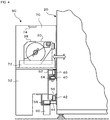
- Fig. 4 is a side view illustrating the schematic configurations of component mounting machine 20 and loader 50
- Fig. 5 is illustrates electrical connections in component mounting system 10.
- a left-right direction is an X-direction
- a front-rear (near side-far-side) direction is a Y-direction
- an up-down direction is a Z-direction.
- Component mounting system 10 includes mounting line 12, loader 50, and management computer 80.
- mounting line 12 is formed by aligning multiple component mounting machines 20 along the X-direction. Board S is conveyed rightwards after board S is conveyed into leftmost component mounting machine 20 and is then conveyed out from rightmost component mounting machine 20. Therefore, a left side of mounting line 12 is referred to as an upstream side, and a right side thereof is referred to as a downstream side.
- component mounting machine 20 is described as a component mounting machine of a type in which boards S are conveyed in two front and rear rows, but the present invention is not limited to this type.
- component mounting machine 20 includes board conveyance devices 21, feeder table 22, head 23, and head moving mechanism 24.
- Board conveyance device 21 conveys a board S in the X-direction.
- Feeder table 22 is a table that is L-shaped in a side view and is provided on a front surface of component mounting machine 20. This feeder table 22 includes multiple slots 22a aligned in the X-direction, and connector 22c provided between two upper and lower positioning holes 22b.
- Head 23 include a nozzle configured to pick up a component supplied to a predetermined component supply position by feeder 30 by means of negative pressure and release the picked up component by means of positive pressure.
- Head moving mechanism 24 moves head 23 in the X- and Y-directions.
- component mounting machine 20 includes mounting control device 28 (refer to fig. 5 ) configured to control the whole of the system.
- Mounting control device 28 is made up of known CPU, ROM, HDD, RAM, and the like and outputs drive signals to board conveyance device 21, head 23, head moving mechanism 24, and the like.
- Feeder 30 is configured as a tape feeder configured to feed out a tape having components installed thereon at a predetermined pitch.
- feeder 30 includes tape reel 32, tape feeding mechanism 33, connector 35, rail member 37, and bar code 38.
- Tape reel 32 holds the tape wound therearound.
- components are installed in multiple recessed sections provided on a tape surface.
- Tape feeding mechanism 33 pulls out the tape from tape reel 32 and feeds out the tape to a predetermined component supply position where the nozzle can pick up a component.
- Connector 35 is provided between two projecting positioning pins 34.
- Rail member 37 is a member having a shape extending in the Y-direction on lower end face of feeder 30.
- Bar code 38 includes, as information, a serial ID that can specify a type of components (a component type) installed on tape reel 32 and is provided on an upper surface of feeder 30.
- a serial ID that can specify a type of components (a component type) installed on tape reel 32 and is provided on an upper surface of feeder 30.
- rail member 37 of feeder 30 is inserted from the front to the rear along slot 22a of feeder table 22.
- two positioning pins 34 of feeder 30 fit into two positioning holes 22b of feeder table 22, and at the same time, connector 35 of feeder 30 fits into connector 22c of feeder table 22, whereby both connectors 35, 22c are electrically connected.
- Feeder 30 includes feeder control device 39 (refer to Fig. 5 ) configured to control the whole of the feeder.
- Feeder control device 39 includes known CPU, ROM, RAM, and the like and outputs a drive signal to tape feeding mechanism 33.
- Feeder control device 39 can communicate with mounting control device 28, management computer 80, and the like via connectors 35, 22c.
- upper guide rail 40, lower guide rail 42, rack gear 44, and non-contact power supply coil 46 are provided on the front surface of component mounting machine 20.
- Upper guide rail 40 is a rail extending in the X-direction and having a U-shaped cross section and has an opening portion facing downward.
- Lower guide rail 42 is a rail extending in the X-direction and having an L-shaped cross section and has a perpendicular surface attached to the front surface of component mounting machine 20 and a horizontal surface extending forward.
- Rack gear 44 is a gear extending in the X direction and having multiple vertical grooves carved on a front surface thereof.
- Non-contact power supply coil 46 is a coil arranged along the X-direction.
- Upper guide rail 40, lower guide rail 42, and rack gear 44 of component mounting machine 20 can detachably be coupled to upper guide rail 40, lower guide rail 42, and rack gear 44 of adjacent component mounting machine 20. Therefore, component mounting machine 20 is standardized, and the number of component mounting machines 20 arranged on mounting line 12 can be increased or decreased.
- loader 50 is configured in two upper and lower stages, the lower stage being traveling table 52, and the upper stage being feeder storage unit 70.
- Traveling table 52 includes upper roller 54, lower roller 56, pinion gear 58, traveling motor 60, and non-contact power receiving coil 62.
- Upper roller 54 is inserted upwardly from an opening section of upper guide rail 40 and is supported in such a manner as to be brought into rolling engagement with a side wall of upper guide rail 40.
- Lower roller 56 is supported in such a manner as to be brought into rolling engagement with a horizontal surface of lower guide rail 42.
- Pinion gear 58 is caused to mesh with rack gear 44.
- a motor shaft of traveling motor 60 is connected to a rotational shaft of pinion gear 58.
- non-contact power receiving coil 62 faces non-contact power supply coil 46 of component mounting machine 20 with a predetermined space maintained from non-contact power receiving coil 46 and receives electric power necessary for traveling or other operations of loader 50 from component mounting machine 20.
- Non-contact power receiving coil 62 may charge a battery (not shown) with the electric power received from component mounting machine 20 for use for traveling or other operations of loader 50.
- traveling table 52 includes further loader control device 64, encoder 66, and optical signal transceiver 68.
- Loader control device 64 is made up known CPU, ROM, HDD, RAM, and the like.
- Encoder 66 detects a position of loader 50 in the X-direction and outputs the detected position to loader control device 64.
- Optical signal transceiver 68 includes light emitting element 68a and light receiving element 68b and is connected to loader control device 64.
- Feeder storage unit 70 stores feeders 30 with which component mounting machines 20 are replenished and also stores feeders 30 that are collected from component mounting machines 20.
- Feeder storage unit 70 includes feeder transfer mechanism 72 and bar code reader 74.
- Feeder transfer mechanism 72 supplies feeders 30 for replenishment and collects feeders 30 for collection. Specifically, when replenishing component mounting machine 20 with feeder 30, feeder transfer mechanism 72 clamps and moves feeder 30 stored in feeder storage unit 70 to the rear along a Y-axis and inserts feeder 30 in question into empty slot 22a in feeder table 22 in component mounting machine 20.
- feeder transfer mechanism 72 clamps and moves feeder 30 held feeder table 22 in component mounting machine 20 to the front along the Y-axis to pull the feeder 30 in question from feeder table 22 and stores the feeder 30 in question back into feeder storage unit 70.
- Power required for feeder transfer mechanism 72 is supplied from component mounting machine 20 via non-contact power supply coil 46.
- Bar code reader 74 reads bar code 38 of feeder 30 so stored back in feeder storage unit 70 and outputs information so read to loader control device 64.
- Management computer 80 is made up of known CPU, ROM, HDD, RAM, and the like and includes display 82 such as LCD and input device 84 such as a keyboard and a mouse as shown in Fig. 5 .
- HDD of management computer 80 stores production job data. The production job data determines which components are mounted on a board S in which order in each component mounting machine 20 and how many boards S with the components so mounted are produced.
- Management computer 80 is connected with mounting control device 28 of each component mounting machine 20 by wire so as to enable bidirectional communication therebetween.
- Management computer 80 is connected with optical signal transceiver 86 including light emitting element 86a and light receiving element 86b. As shown in fig. 1 , optical signal transceiver 86 is fixed to an upstream end portion of mounting line 12.
- Light-emitting element 86a and light-receiving element 86b of optical signal transceiver 86 are connected with light receiving element 68b and light emitting element 68a of optical signal transceiver 68 of loader control device 64, respectively, by light so as to enable a wireless communication therebetween.
- This wireless communication path is referred to as optical wireless communication path C.
- Optical wireless communication path C is provided along the X-direction (that is, the direction in which multiple component mounting machines 20 are arranged).
- Management computer 80 can communicate with loader control device 64 bidirectionally by way of optical wireless communication path C. As light, visible light is used, but infrared light may be used. Alternatively, laser light may be used. Since loader 50 is moved in the X-direction, loader 50 can move towards and away from optical signal transceiver 86.
- Mounting control device 28 of component mounting machine 20 controls head moving mechanism 24 so that the nozzle of head 23 arrives at the component supply position of feeder 30, causing the nozzle to suction pick up a component supplied by feeder 30. Thereafter, mounting control device 28 controls head moving mechanism 24 so that the component picked up by the nozzle arrives at a predetermined mounting position on board S, causing the nozzle to release the component to be mounted at the mounting position. Mounting control device 28 performs this mounting operation on all components to be mounted on board S. In addition, mounting control device 28 performs component mounting on the number of boards S set in the production job data.
- Mounting controller 28 of component mounting machine 20 subtracts the number of component removed from feeder 30 from the number of components remaining in feeder 30 each time a component is removed from feeder 30, deems that a component shortage is coming soon when the number of components remaining in the feeder becomes a predetermined threshold or smaller, and outputs a request for replenishing feeder table 22 with feeder 30 of the same type to management computer 80.
- management computer 80 When the replenishment request is inputted into management computer 80, management computer 80 displays on display 82 a screen instructing the operator to set feeder 30 installing components of a type requested to be supplied for replenishment in feeder storage unit 70 of loader 50. After seeing this screen, the operator sets feeder 30 installing components of that type in feeder storage unit 70 of loader 50.
- bar code 38 of feeder 30 is read by bar code reader 74, and a serial ID of bar code 38 in question is transmitted from loader control device 64 to management computer 80 via optical wireless communication path C.
- management computer 80 Since management computer 80 stores data regarding components in association with each serial ID in the HDD, management computer 80 determines whether the type of components in feeder 30 set in loader 50 is the same as the type of components requested to be supplied for replenishment of feeder table 22. If it determines that both the types do not coincide with each other, management computer 80 reports an error. If it is determines that both the types coincide with each other, management computer 80 outputs a feeder replacement request to loader control device 64 via optical wireless communication path C.
- the feeder replacement request is a command for loader 50 to perform a feeder replacement in component mounting machine 20 to which the replenishment request is outputted.
- the feeder replacement request includes positional information on slot 22a of feeder table 22 of component mounting machine 20, specifically, positional information on slot 22a into which feeder 30 to be supplied for replenishment is inserted and also positional information on slot 22a in which feeder 30 that has run out of components is kept inserted.
- loader control device 64 controls traveling motor 60 so that loader 50 arrives at a position lying ahead of component mounting machine 20 which has output the replenishment request. Specifically, traveling motor 60 is controlled so that feeder 30 set in feeder storage unit 70 comes to face slot 22a into which feeder 30 in question is to be inserted. In that state, loader control device 64 controls feeder transfer mechanism 72 so that feeder 30 set in feeder storage unit 70 is inserted into slot 22a that feeder 30 in question faces. As a result, new feeder 30 is supplied into component mounting machine 20, whereby component mounting machine 20 in question is replenished with requested feeder 30.
- loader control device 64 controls traveling motor 60 so that a feeder recovery position in feeder storage unit 70 faces feeder 30 that has run out of components on feeder table 22.
- loader control device 64 controls feeder transfer mechanism 72 so that feeder 30 that has run out of components is pulled into the feeder recovery position in feeder storage unit 70.
- feeder 30 that has run out of components is recovered in loader 50.
- component mounting machine 20 can continue the production without interrupting the mounting operation only by switching the component supply position of feeder 30 that has run out of components (the position where the component is suction picked up by the nozzle provided on the head 23) to a component supply position of new feeder 30.
- Component mounting system 10 of the present embodiment corresponds to a component mounting system of the present disclosure
- mounting line 12 corresponds to a mounting line
- loader 50 corresponds to a mobile work device
- management computer 80 corresponds to a management device
- optical wireless communication path C corresponds to an optical wireless communication path.
- feeder 30 corresponds to a component supply device.
- management computer 80 transmits a signal to loader 50 via optical wireless communication path C provided along the X-direction, which is the direction in which component mounting machines 20 are arranged. That is, a transmission from management computer 80 to loader 50 can be performed without using a cable. Therefore, even though the number of component mounting machines 20 constituting mounting line 12 is increased or decreased to thereby change the length of mounting line 12, a transmission from management computer 80 to loader 50 can be performed without any problem.
- Management computer 80 is connected to an optical signal transceiver 86 fixed to an end portion of mounting line 12, and loader 50 is connected with optical signal transceiver 86 via optical wireless communication path C and moves towards and away from optical signal transceiver 86. Therefore, while loader 50 moves from an end to an end of mounting line 12, a communication can be performed between loader 50 and management computer 80 using optical wireless communication path C.
- loader 50 is supplied with power without contact from individual component mounting machines 20 arranged along mounting line 12.
- a power supply cord may interrupt the movement of loader 50, but such a fear is eliminated since power is supplied with non-contact manner.
- management computer 80 and loader control device 64 are performed via a cableveyor or a curtain cable, with the embodiment described above, noise and dust generation can be eliminated.
- a communication between management computer 80 and loader control device 64 is performed by wireless communication using radio waves, it is necessary to prepare a communication unit that conforms to the radio wave law of each country, but such a preparation is not necessary in the embodiment described above because optical radio communication is used.
- one working device set including loader 50, optical signal transceiver 86, and optical wireless communication path C is provided in front of mounting line 12, but as shown in fig. 6 , the working device set WS may be provided on each of an upstream side and a downstream side of mounting line 12.
- upstream loader 50 performs an optical wireless communication with management computer 80 via upstream optical signal transceiver 86
- a downstream loader 50 performs an optical wireless communication with management computer 80 via downstream optical signal transceiver 86.
- respective loaders 50 on the upstream and downstream sides of mounting line 12 are configured to move on the same straight line in the X-direction. Therefore, when compared with the case where two loaders 50 move on different straight lines in the X-direction, the overall configuration can be made compact.
- management computer 80 preferably controls the movement of two loader 50 so that two loaders 50 are separated from each other by a predetermined inter-device distance or greater.
- management computer 80 receives and monitors positions of loaders 50 in the X-direction detected by encoders 66 of loaders 50 from loader control devices 64 and transmits a command signal to loader control devices 64 so that two loaders 50 are separated from each other by the predetermined distance or greater. As a result, colliding of two loaders 50 can be avoided.
- feeder 30 is described as functioning as the component supply device, but the present invention is not particularly limited to feeder 30 and hence may function as, for example, a component tray or a unit for supplying a component tray.
- the component supply device is not limited to a device such as feeder 30 for supplying components to be mounted on board S and hence may be, for example, a device for supplying a head or a nozzle stocker for supplying a replacement nozzle for attachment to the head.
- loader 50 is described as executing both the supply of feeders 30 for replenishment and the collecting of used feeders 30, but the present invention is not particularly limited thereto, and hence, for example, loader 50 may be caused to execute only one of the supply and the collecting.
- loader 50 is described as traveling using traveling motor 60, but the present invention is not particularly limited thereto.
- loader 50 may be an unmanned conveyance vehicle configured to travel by means of a magnetic induction action of a guide line embedded in a floor surface.
- the power for operating loader 50 is described as being supplied from component mounting machines 20 via non-contact power supply coil 46, but the present invention is not particularly limited thereto.
- a battery may be mounted on loader 50.
- the rotational motion of traveling motor 60 is converted into the linear motion using rack gear 44 and pinion gear 58, but a rotational motion of traveling motor 60 may be converted into a linear motion using a chain instead of rack gear 44 and a sprocket wheel instead of pinion gear 58.
- mounting line 12 is described as being formed by aligning multiple component mounting machines 20 side by side in the X direction, but a printing machine for printing solder on board S or a printing inspector for inspecting a printing status by the printing machine may be arranged on an upstream side of component mounting machine 20 disposed in a most upstream position.
- a component inspector for inspecting components on board S or a reflow machine for performing a reflow of solder may be disposed on a downstream side of component mounting machine 20 disposed in a most downstream position.
- the component mounting system of the present disclosure may be configured as follows.
- the management device may be connected to an optical signal transceiver fixed to an end of the mounting line, and the mobile work device may be connected with the optical signal transceiver via the optical wireless communication path and may move towards and away from the optical signal transceiver.
- the mobile work device moves from the end to the end of the mounting line, a transmission from the management device to the mobile work device can be performed by making use of using the optical wireless communication path.
- the work device set including the mobile work device, the optical signal transceiver, and the optical wireless communication path may be provided on each of a first end side and a second end side of the mounting line.
- the mobile work devices on the first end side and the second end side of the mounting line may move on the same straight line in the predetermined direction.
- the overall configuration can be made compact.
- the management device may control the movement of each mobile work device so that the mobile work devices on the first end side and the second end side of the mounting line are separated a predetermined inter-device distance or greater from each other. As a result, a collision of the two mobile work devices can be avoided.
- the mounting line may increase or decrease the number of the component mounting machines.
- the mobile work device may be supplied with power from each of the component mounting machines that are arranged along the mounting line, the power being supplied with non-contact manner.
- the mobile work device is powered using a wire, there may be fears that the movement of the mobile work device is interrupted by a power supply cord; however, in the embodiment, since power is supplied with non-contact manner, there are no such fears.
- the present invention can be applied to various industries where components are mounted on boards.
Landscapes
- Engineering & Computer Science (AREA)
- Manufacturing & Machinery (AREA)
- Microelectronics & Electronic Packaging (AREA)
- Operations Research (AREA)
- Automation & Control Theory (AREA)
- Physics & Mathematics (AREA)
- Electromagnetism (AREA)
- Computer Networks & Wireless Communication (AREA)
- Signal Processing (AREA)
- Supply And Installment Of Electrical Components (AREA)
Abstract
Description
- This description discloses a component mounting system.
- There is known a component mounting system including a replenishing device for replenishing or collecting a component supply device to and from multiple component mounting machines arranged in a mounting line (for example, patent literature 1). This replenishing device can run along the mounting line. The replenishing device is configured to transmit information to the mounting machines without contacting them and is controlled to move to a component mounting machine that needs component replenishment. Components are managed by a management computer.
- Patent Literature 1: International Publication No.
WO 2014/010083 - However, since the replenishing device and the management computer cannot communicate directly with each other, the management computer cannot issue a command directly to the replenishing device. In addition, in a case of an attempt being made for the replenishing device and the management computer to communicate with each other directly, the replenishing device and the management computer may be connected together by a cable stored in a cableveyor (TM), however, in that case, when the number of component mounting machines is changed, the length of the mounting line is thereby also changed, and there may be a drawback such that the change in the number or the length cannot be dealt with by the cableveyor. In addition, there have also been fears that a cable may interfere with work.
- The present disclosure has been made in order to solve the problems described above, and a main object of the disclosure is to enable a transmission to be made from a management device to a mobile work machine without any problem even though the length of a mounting line is changed.
- According to the present disclosure, there is provided a component mounting system including:
- a mounting line in which multiple component mounting machines, each including a component supply device, are arranged along a predetermined direction;
- a mobile work device, being configured to move along the predetermined direction, which at least replenishes or collects the component supply device to or from each component mounting machine; and
- a management device configured to transmit a signal to the mobile work device via a communication path,
- wherein the communication path is an optical wireless communication path provided along the predetermined direction.
- In this component mounting system, the management device transmits a signal to the mobile work device via the optical wireless communication path provided along the predetermined direction which is the direction in which the component mounting devices are arranged. That is, a signal can be transmitted from the management device to the mobile work device without using a cable. As a result, even though the length of the mounting line is changed due to a change in the number of component mounting machines constituting the mounting line, the transmission of a signal from the management device to the mobile work device can be performed without any problem.
-
- [
Fig. 1] Fig. 1 is a plan view illustrating a schematic configuration ofcomponent mounting system 10. - [
Fig. 2] Fig. 2 is a perspective view illustrating schematic configurations ofcomponent mounting machine 20 andloader 50. - [
Fig. 3] Fig. 3 is a perspective view illustrating a schematic configuration offeeder 30. - [
Fig. 4] Fig. 4 is a side view illustrating the schematic configurations ofcomponent mounting machine 20 andloader 50. - [
Fig. 5] Fig. 5 illustrates electrical connections incomponent mounting system 10. - [
Fig. 6] Fig. 6 is a plan view illustrating a schematic configuration of another example of a component mounting system. - Hereinafter, referring to drawings, preferred embodiments of a component mounting system of the present disclosure will be described.
Fig. 1 is a plan view illustrating a schematic configuration ofcomponent mounting system 10,Fig. 2 is a perspective view illustrating schematic configurations ofcomponent mounting machine 20 andloader 50,Fig. 3 is a perspective view illustrating a schematic configuration offeeder 30,Fig. 4 is a side view illustrating the schematic configurations ofcomponent mounting machine 20 andloader 50, andFig. 5 is illustrates electrical connections incomponent mounting system 10. InFig. 1 , a left-right direction is an X-direction, a front-rear (near side-far-side) direction is a Y-direction, and an up-down direction is a Z-direction. -
Component mounting system 10 includesmounting line 12,loader 50, andmanagement computer 80. - As shown in
Fig. 1 ,mounting line 12 is formed by aligning multiplecomponent mounting machines 20 along the X-direction. Board S is conveyed rightwards after board S is conveyed into leftmostcomponent mounting machine 20 and is then conveyed out from rightmostcomponent mounting machine 20. Therefore, a left side ofmounting line 12 is referred to as an upstream side, and a right side thereof is referred to as a downstream side. In the present embodiment, for example,component mounting machine 20 is described as a component mounting machine of a type in which boards S are conveyed in two front and rear rows, but the present invention is not limited to this type. - As shown in
Fig. 2 ,component mounting machine 20 includesboard conveyance devices 21, feeder table 22,head 23, andhead moving mechanism 24.Board conveyance device 21 conveys a board S in the X-direction. Feeder table 22 is a table that is L-shaped in a side view and is provided on a front surface ofcomponent mounting machine 20. This feeder table 22 includesmultiple slots 22a aligned in the X-direction, andconnector 22c provided between two upper andlower positioning holes 22b.Head 23 include a nozzle configured to pick up a component supplied to a predetermined component supply position byfeeder 30 by means of negative pressure and release the picked up component by means of positive pressure.Head moving mechanism 24 moveshead 23 in the X- and Y-directions. In addition,component mounting machine 20 includes mounting control device 28 (refer tofig. 5 ) configured to control the whole of the system.Mounting control device 28 is made up of known CPU, ROM, HDD, RAM, and the like and outputs drive signals to boardconveyance device 21,head 23,head moving mechanism 24, and the like. - Feeder 30 is configured as a tape feeder configured to feed out a tape having components installed thereon at a predetermined pitch. As shown in
Fig. 3 ,feeder 30 includestape reel 32,tape feeding mechanism 33,connector 35,rail member 37, andbar code 38.Tape reel 32 holds the tape wound therearound. In the tape, components are installed in multiple recessed sections provided on a tape surface.Tape feeding mechanism 33 pulls out the tape fromtape reel 32 and feeds out the tape to a predetermined component supply position where the nozzle can pick up a component.Connector 35 is provided between twoprojecting positioning pins 34.Rail member 37 is a member having a shape extending in the Y-direction on lower end face offeeder 30.Bar code 38 includes, as information, a serial ID that can specify a type of components (a component type) installed ontape reel 32 and is provided on an upper surface offeeder 30. Whenfeeder 30 is set on feeder table 22,rail member 37 offeeder 30 is inserted from the front to the rear alongslot 22a of feeder table 22. When the insertion is completed, twopositioning pins 34 offeeder 30 fit into twopositioning holes 22b of feeder table 22, and at the same time,connector 35 offeeder 30 fits intoconnector 22c of feeder table 22, whereby bothconnectors feeder 30 is removed from feeder table 22, a procedure opposite to the setting procedure is performed.Feeder 30 includes feeder control device 39 (refer toFig. 5 ) configured to control the whole of the feeder.Feeder control device 39 includes known CPU, ROM, RAM, and the like and outputs a drive signal totape feeding mechanism 33.Feeder control device 39 can communicate withmounting control device 28,management computer 80, and the like viaconnectors - As shown in
Figs. 2 and4 ,upper guide rail 40,lower guide rail 42,rack gear 44, and non-contactpower supply coil 46 are provided on the front surface ofcomponent mounting machine 20.Upper guide rail 40 is a rail extending in the X-direction and having a U-shaped cross section and has an opening portion facing downward.Lower guide rail 42 is a rail extending in the X-direction and having an L-shaped cross section and has a perpendicular surface attached to the front surface ofcomponent mounting machine 20 and a horizontal surface extending forward.Rack gear 44 is a gear extending in the X direction and having multiple vertical grooves carved on a front surface thereof. Non-contactpower supply coil 46 is a coil arranged along the X-direction.Upper guide rail 40,lower guide rail 42, andrack gear 44 ofcomponent mounting machine 20 can detachably be coupled toupper guide rail 40,lower guide rail 42, andrack gear 44 of adjacentcomponent mounting machine 20. Therefore,component mounting machine 20 is standardized, and the number ofcomponent mounting machines 20 arranged on mountingline 12 can be increased or decreased. - As shown in
fig. 4 ,loader 50 is configured in two upper and lower stages, the lower stage being traveling table 52, and the upper stage beingfeeder storage unit 70. - Traveling table 52 includes
upper roller 54,lower roller 56,pinion gear 58, travelingmotor 60, and non-contactpower receiving coil 62.Upper roller 54 is inserted upwardly from an opening section ofupper guide rail 40 and is supported in such a manner as to be brought into rolling engagement with a side wall ofupper guide rail 40.Lower roller 56 is supported in such a manner as to be brought into rolling engagement with a horizontal surface oflower guide rail 42.Pinion gear 58 is caused to mesh withrack gear 44. A motor shaft of travelingmotor 60 is connected to a rotational shaft ofpinion gear 58. Whenpinion gear 58 meshing withrack gear 44 extending in the X-direction is rotated by travelingmotor 60, traveling table 52 and henceloader 50 move in the X-direction whileupper roller 54 is rolling on the side wall ofupper guide rail 40 andlower roller 56 is rolling on the horizontal surface oflower guide rail 42. On the other hand, non-contactpower receiving coil 62 faces non-contactpower supply coil 46 ofcomponent mounting machine 20 with a predetermined space maintained from non-contactpower receiving coil 46 and receives electric power necessary for traveling or other operations ofloader 50 fromcomponent mounting machine 20. Non-contactpower receiving coil 62 may charge a battery (not shown) with the electric power received fromcomponent mounting machine 20 for use for traveling or other operations ofloader 50. - As shown in
fig. 5 , traveling table 52 includes furtherloader control device 64,encoder 66, andoptical signal transceiver 68.Loader control device 64 is made up known CPU, ROM, HDD, RAM, and the like.Encoder 66 detects a position ofloader 50 in the X-direction and outputs the detected position toloader control device 64.Optical signal transceiver 68 includeslight emitting element 68a andlight receiving element 68b and is connected toloader control device 64. -
Feeder storage unit 70stores feeders 30 with whichcomponent mounting machines 20 are replenished and also storesfeeders 30 that are collected fromcomponent mounting machines 20.Feeder storage unit 70 includesfeeder transfer mechanism 72 andbar code reader 74.Feeder transfer mechanism 72supplies feeders 30 for replenishment and collectsfeeders 30 for collection. Specifically, when replenishingcomponent mounting machine 20 withfeeder 30,feeder transfer mechanism 72 clamps and movesfeeder 30 stored infeeder storage unit 70 to the rear along a Y-axis and insertsfeeder 30 in question intoempty slot 22a in feeder table 22 incomponent mounting machine 20. Additionally, when collectingfeeder 30 fromcomponent mounting machine 20,feeder transfer mechanism 72 clamps and movesfeeder 30 held feeder table 22 incomponent mounting machine 20 to the front along the Y-axis to pull thefeeder 30 in question from feeder table 22 and stores thefeeder 30 in question back intofeeder storage unit 70. Power required forfeeder transfer mechanism 72 is supplied fromcomponent mounting machine 20 via non-contactpower supply coil 46.Bar code reader 74 readsbar code 38 offeeder 30 so stored back infeeder storage unit 70 and outputs information so read toloader control device 64. -
Management computer 80 is made up of known CPU, ROM, HDD, RAM, and the like and includesdisplay 82 such as LCD andinput device 84 such as a keyboard and a mouse as shown inFig. 5 . HDD ofmanagement computer 80 stores production job data. The production job data determines which components are mounted on a board S in which order in eachcomponent mounting machine 20 and how many boards S with the components so mounted are produced.Management computer 80 is connected with mountingcontrol device 28 of eachcomponent mounting machine 20 by wire so as to enable bidirectional communication therebetween.Management computer 80 is connected withoptical signal transceiver 86 includinglight emitting element 86a andlight receiving element 86b. As shown infig. 1 ,optical signal transceiver 86 is fixed to an upstream end portion of mountingline 12. Light-emittingelement 86a and light-receivingelement 86b ofoptical signal transceiver 86 are connected with light receivingelement 68b and light emittingelement 68a ofoptical signal transceiver 68 ofloader control device 64, respectively, by light so as to enable a wireless communication therebetween. This wireless communication path is referred to as optical wireless communication path C. Optical wireless communication path C is provided along the X-direction (that is, the direction in which multiplecomponent mounting machines 20 are arranged).Management computer 80 can communicate withloader control device 64 bidirectionally by way of optical wireless communication path C. As light, visible light is used, but infrared light may be used. Alternatively, laser light may be used. Sinceloader 50 is moved in the X-direction,loader 50 can move towards and away fromoptical signal transceiver 86. - Next, the operation of
component mounting machine 20 will be described. Mountingcontrol device 28 ofcomponent mounting machine 20 controls head movingmechanism 24 so that the nozzle ofhead 23 arrives at the component supply position offeeder 30, causing the nozzle to suction pick up a component supplied byfeeder 30. Thereafter, mountingcontrol device 28 controls head movingmechanism 24 so that the component picked up by the nozzle arrives at a predetermined mounting position on board S, causing the nozzle to release the component to be mounted at the mounting position. Mountingcontrol device 28 performs this mounting operation on all components to be mounted on board S. In addition, mountingcontrol device 28 performs component mounting on the number of boards S set in the production job data. - Mounting
controller 28 ofcomponent mounting machine 20 subtracts the number of component removed fromfeeder 30 from the number of components remaining infeeder 30 each time a component is removed fromfeeder 30, deems that a component shortage is coming soon when the number of components remaining in the feeder becomes a predetermined threshold or smaller, and outputs a request for replenishing feeder table 22 withfeeder 30 of the same type tomanagement computer 80. - When the replenishment request is inputted into
management computer 80,management computer 80 displays on display 82 a screen instructing the operator to setfeeder 30 installing components of a type requested to be supplied for replenishment infeeder storage unit 70 ofloader 50. After seeing this screen, the operator setsfeeder 30 installing components of that type infeeder storage unit 70 ofloader 50. Whenfeeder 30 is set infeeder storage unit 70,bar code 38 offeeder 30 is read bybar code reader 74, and a serial ID ofbar code 38 in question is transmitted fromloader control device 64 tomanagement computer 80 via optical wireless communication path C. Sincemanagement computer 80 stores data regarding components in association with each serial ID in the HDD,management computer 80 determines whether the type of components infeeder 30 set inloader 50 is the same as the type of components requested to be supplied for replenishment of feeder table 22. If it determines that both the types do not coincide with each other,management computer 80 reports an error. If it is determines that both the types coincide with each other,management computer 80 outputs a feeder replacement request toloader control device 64 via optical wireless communication path C. The feeder replacement request is a command forloader 50 to perform a feeder replacement incomponent mounting machine 20 to which the replenishment request is outputted. The feeder replacement request includes positional information onslot 22a of feeder table 22 ofcomponent mounting machine 20, specifically, positional information onslot 22a into whichfeeder 30 to be supplied for replenishment is inserted and also positional information onslot 22a in whichfeeder 30 that has run out of components is kept inserted. - When the feeder replacement request is input into
loader control device 64 frommanagement computer 80 via optical wireless communication path C,loader control device 64controls traveling motor 60 so thatloader 50 arrives at a position lying ahead ofcomponent mounting machine 20 which has output the replenishment request. Specifically, travelingmotor 60 is controlled so thatfeeder 30 set infeeder storage unit 70 comes to faceslot 22a into whichfeeder 30 in question is to be inserted. In that state,loader control device 64 controlsfeeder transfer mechanism 72 so thatfeeder 30 set infeeder storage unit 70 is inserted intoslot 22a thatfeeder 30 in question faces. As a result,new feeder 30 is supplied intocomponent mounting machine 20, wherebycomponent mounting machine 20 in question is replenished with requestedfeeder 30. - Thereafter,
loader control device 64controls traveling motor 60 so that a feeder recovery position infeeder storage unit 70 facesfeeder 30 that has run out of components on feeder table 22. In this state,loader control device 64 controlsfeeder transfer mechanism 72 so thatfeeder 30 that has run out of components is pulled into the feeder recovery position infeeder storage unit 70. As a result,feeder 30 that has run out of components is recovered inloader 50. - In this manner, the replenishment of feeder table 22 with
new feeder 30 installing the same type of components as the type of components that have been used up and the recovery offeeder 30 that has run out of components are automatically performed byloader 50. Therefore,component mounting machine 20 can continue the production without interrupting the mounting operation only by switching the component supply position offeeder 30 that has run out of components (the position where the component is suction picked up by the nozzle provided on the head 23) to a component supply position ofnew feeder 30. - Here, the correspondence relationship between the constituent elements of the present embodiment and constituent elements of the present disclosure will be clarified.
Component mounting system 10 of the present embodiment corresponds to a component mounting system of the present disclosure, mountingline 12 corresponds to a mounting line,loader 50 corresponds to a mobile work device,management computer 80 corresponds to a management device, and optical wireless communication path C corresponds to an optical wireless communication path. In addition,feeder 30 corresponds to a component supply device. - In the
component mounting system 10 described above,management computer 80 transmits a signal toloader 50 via optical wireless communication path C provided along the X-direction, which is the direction in whichcomponent mounting machines 20 are arranged. That is, a transmission frommanagement computer 80 toloader 50 can be performed without using a cable. Therefore, even though the number ofcomponent mounting machines 20constituting mounting line 12 is increased or decreased to thereby change the length of mountingline 12, a transmission frommanagement computer 80 toloader 50 can be performed without any problem. -
Management computer 80 is connected to anoptical signal transceiver 86 fixed to an end portion of mountingline 12, andloader 50 is connected withoptical signal transceiver 86 via optical wireless communication path C and moves towards and away fromoptical signal transceiver 86. Therefore, whileloader 50 moves from an end to an end of mountingline 12, a communication can be performed betweenloader 50 andmanagement computer 80 using optical wireless communication path C. - Further,
loader 50 is supplied with power without contact from individualcomponent mounting machines 20 arranged along mountingline 12. In the case whereloader 50 is powered by a wire, a power supply cord may interrupt the movement ofloader 50, but such a fear is eliminated since power is supplied with non-contact manner. - Furthermore, as compared with a case where communication between
management computer 80 andloader control device 64 is performed via a cableveyor or a curtain cable, with the embodiment described above, noise and dust generation can be eliminated. In addition, in the case where a communication betweenmanagement computer 80 andloader control device 64 is performed by wireless communication using radio waves, it is necessary to prepare a communication unit that conforms to the radio wave law of each country, but such a preparation is not necessary in the embodiment described above because optical radio communication is used. - The present invention is not limited in any way to the embodiment described above, and hence, needless to say, the present invention can be carried out in various forms without departing from the technical scope thereof.
- For example, in the embodiment described above, one working device
set including loader 50,optical signal transceiver 86, and optical wireless communication path C is provided in front of mountingline 12, but as shown infig. 6 , the working device set WS may be provided on each of an upstream side and a downstream side of mountingline 12. In this case,upstream loader 50 performs an optical wireless communication withmanagement computer 80 via upstreamoptical signal transceiver 86, and adownstream loader 50 performs an optical wireless communication withmanagement computer 80 via downstreamoptical signal transceiver 86. As a result, since twoloaders 50 can be used to supplyfeeders 30 for replenishment and recover usedfeeders 30 for one mountingline 12, the operation time is reduced. Infig. 6 ,respective loaders 50 on the upstream and downstream sides of mountingline 12 are configured to move on the same straight line in the X-direction. Therefore, when compared with the case where twoloaders 50 move on different straight lines in the X-direction, the overall configuration can be made compact. When twoloaders 50 move on the same straight line in the X-direction as described above,management computer 80 preferably controls the movement of twoloader 50 so that twoloaders 50 are separated from each other by a predetermined inter-device distance or greater. Specifically,management computer 80 receives and monitors positions ofloaders 50 in the X-direction detected byencoders 66 ofloaders 50 fromloader control devices 64 and transmits a command signal toloader control devices 64 so that twoloaders 50 are separated from each other by the predetermined distance or greater. As a result, colliding of twoloaders 50 can be avoided. - In the embodiment described above,
feeder 30 is described as functioning as the component supply device, but the present invention is not particularly limited tofeeder 30 and hence may function as, for example, a component tray or a unit for supplying a component tray. In addition, the component supply device is not limited to a device such asfeeder 30 for supplying components to be mounted on board S and hence may be, for example, a device for supplying a head or a nozzle stocker for supplying a replacement nozzle for attachment to the head. - In the embodiment described above,
loader 50 is described as executing both the supply offeeders 30 for replenishment and the collecting of usedfeeders 30, but the present invention is not particularly limited thereto, and hence, for example,loader 50 may be caused to execute only one of the supply and the collecting. - In the embodiment described above, as a mobile work device,
loader 50 is described as traveling using travelingmotor 60, but the present invention is not particularly limited thereto. For example,loader 50 may be an unmanned conveyance vehicle configured to travel by means of a magnetic induction action of a guide line embedded in a floor surface. - In the embodiment described above, the power for operating
loader 50 is described as being supplied fromcomponent mounting machines 20 via non-contactpower supply coil 46, but the present invention is not particularly limited thereto. For example, a battery may be mounted onloader 50. - In the embodiment described above, the rotational motion of traveling
motor 60 is converted into the linear motion usingrack gear 44 andpinion gear 58, but a rotational motion of travelingmotor 60 may be converted into a linear motion using a chain instead ofrack gear 44 and a sprocket wheel instead ofpinion gear 58. - In the embodiment described above, mounting
line 12 is described as being formed by aligning multiplecomponent mounting machines 20 side by side in the X direction, but a printing machine for printing solder on board S or a printing inspector for inspecting a printing status by the printing machine may be arranged on an upstream side ofcomponent mounting machine 20 disposed in a most upstream position. Alternatively, a component inspector for inspecting components on board S or a reflow machine for performing a reflow of solder may be disposed on a downstream side ofcomponent mounting machine 20 disposed in a most downstream position. - The component mounting system of the present disclosure may be configured as follows.
- In the component mounting system of the present disclosure, the management device may be connected to an optical signal transceiver fixed to an end of the mounting line, and the mobile work device may be connected with the optical signal transceiver via the optical wireless communication path and may move towards and away from the optical signal transceiver. As a result, while the mobile work device moves from the end to the end of the mounting line, a transmission from the management device to the mobile work device can be performed by making use of using the optical wireless communication path.
- In the component mounting system of the present disclosure, the work device set including the mobile work device, the optical signal transceiver, and the optical wireless communication path may be provided on each of a first end side and a second end side of the mounting line. As a result, since the work can be performed on the mounting line using the two mobile work devices, the work time can be reduced.
- In the component mounting system of the present disclosure, when the work device set is provided on each of the first end side and the second end side of the mounting line, the mobile work devices on the first end side and the second end side of the mounting line may move on the same straight line in the predetermined direction. As a result, compared with a case where two mobile work devices move on separate straight lines in a predetermined direction, the overall configuration can be made compact.
- In the component mounting system of the present disclosure, when the mobile work devices on the first end side and the second end side of the mounting line move on the same straight line in the predetermined direction, the management device may control the movement of each mobile work device so that the mobile work devices on the first end side and the second end side of the mounting line are separated a predetermined inter-device distance or greater from each other. As a result, a collision of the two mobile work devices can be avoided.
- In the component mounting system of the present disclosure, the mounting line may increase or decrease the number of the component mounting machines.
- In the component mounting system of the present disclosure, the mobile work device may be supplied with power from each of the component mounting machines that are arranged along the mounting line, the power being supplied with non-contact manner. In the case where the mobile work device is powered using a wire, there may be fears that the movement of the mobile work device is interrupted by a power supply cord; however, in the embodiment, since power is supplied with non-contact manner, there are no such fears.
- The present invention can be applied to various industries where components are mounted on boards.
- 10 component mounting system, 12 mounting line, 20 component mounting machine, 21 board conveyance device, 22 feeder table, 22a slot, 22b positioning hole, 22c connector, 23 head, 24 head moving mechanism, 28 mounting control device, 30 feeder, 32 tape reel, 33 tape feeding mechanism, 34 positioning pin, 35 connector, 37 rail member, 38 bar code, 39 feeder control device, 40 upper guide rail, 42 lower guide rail, 44 rack gear, 46 non-contact power supply coil, 50 loader, 52 traveling table, 54 upper roller, 56 lower roller, 58 pinion gear, 60 traveling motor, 62 non-contact power receiving coil, 64 loader control device, 66 encoder, 68 optical signal transceiver, 68a light emitting device, 68b light receiving device, 70 feeder storage unit, 72 feeder transfer mechanism, 74 bar code reader, 80 management computer, 82 display, 84 input device, 86 optical signal transceiver, 86a light emitting element, 86b light receiving element, C optical wireless communication path, WS work device set.
Claims (7)
- A component mounting system comprising:a mounting line in which multiple component mounting machines, each including a component supply device, are arranged along a predetermined direction;a mobile work device, being configured to move along the predetermined direction, which at least replenishes or collects the component supply device to or from each component mounting machine; anda management device configured to transmit a signal to the mobile work device via a communication path,wherein the communication path is an optical wireless communication path provided along the predetermined direction.
- The component mounting system according to claim 1,
wherein the management device is connected with an optical signal transceiver fixed to an end portion of the mounting line, and
wherein the mobile work device is connected with the optical signal transceiver via the optical wireless communication path and is configured to move towards and away from the optical signal transceiver. - The component mounting system according to claim 2,
wherein a work device set including the mobile work device, the optical signal transceiver, and the optical wireless communication path is provided on each of a first end side and a second end side of the mounting line. - The component mounting system according to claim 3,
wherein the mobile work devices provided individually on the first end side and the second end side of the mounting line are configured to move on a same straight line in the predetermined direction. - The component mounting system according to claim 4,
wherein the management device is configured to control movements of the mobile work devices on the first end side and the second end side of the mounting line so that the mobile work devices are separated from each other by a predetermined inter-device distance or greater. - The component mounting system according to any one of claims 1 to 5,
wherein the mounting line is configured such that the number of the component mounting machines can be increased or decreased. - The component mounting system according to any one of claims 1 to 6,
wherein the mobile work device is configured to be supplied with power from each of the component mounting machines arranged along the mounting line, the power being supplied in a non-contact manner.
Applications Claiming Priority (1)
| Application Number | Priority Date | Filing Date | Title |
|---|---|---|---|
| PCT/JP2017/012945 WO2018179147A1 (en) | 2017-03-29 | 2017-03-29 | Component mounting system |
Publications (3)
| Publication Number | Publication Date |
|---|---|
| EP3606314A1 true EP3606314A1 (en) | 2020-02-05 |
| EP3606314A4 EP3606314A4 (en) | 2020-03-25 |
| EP3606314B1 EP3606314B1 (en) | 2025-09-24 |
Family
ID=63677350
Family Applications (1)
| Application Number | Title | Priority Date | Filing Date |
|---|---|---|---|
| EP17902837.8A Active EP3606314B1 (en) | 2017-03-29 | 2017-03-29 | Component mounting system |
Country Status (5)
| Country | Link |
|---|---|
| US (1) | US11212951B2 (en) |
| EP (1) | EP3606314B1 (en) |
| JP (1) | JP6872007B2 (en) |
| CN (1) | CN110447317B (en) |
| WO (1) | WO2018179147A1 (en) |
Families Citing this family (9)
| Publication number | Priority date | Publication date | Assignee | Title |
|---|---|---|---|---|
| JP7111830B2 (en) * | 2018-11-15 | 2022-08-02 | 株式会社Fuji | working system |
| US11765877B2 (en) * | 2019-03-05 | 2023-09-19 | Fuji Corporation | Component mounting system |
| US12048100B2 (en) | 2019-03-12 | 2024-07-23 | Fuji Corporation | Management device, mobile work device, mounting system, and management method |
| US12207412B2 (en) * | 2020-01-14 | 2025-01-21 | Fuji Corporation | Article transport system |
| JP7349392B2 (en) * | 2020-03-10 | 2023-09-22 | 株式会社Fuji | Control device, mounting system and control method |
| CN117256205A (en) | 2021-06-23 | 2023-12-19 | 株式会社富士 | Management device, installation system and production method |
| JP7781412B2 (en) * | 2021-10-14 | 2025-12-08 | 北陽電機株式会社 | Communication system, optical transmission device, and communication method |
| JP7252384B1 (en) | 2022-02-01 | 2023-04-04 | Dmg森精機株式会社 | Conveyor |
| JP2025159697A (en) * | 2025-02-03 | 2025-10-21 | Kne株式会社 | Work equipment |
Family Cites Families (20)
| Publication number | Priority date | Publication date | Assignee | Title |
|---|---|---|---|---|
| US5193268A (en) * | 1989-11-07 | 1993-03-16 | Sanyo Electric Co., Ltd. | Parts feeding system utilizing an unmanned conveying machine |
| JP2792956B2 (en) * | 1989-11-10 | 1998-09-03 | 三洋電機株式会社 | Parts supply system |
| CA2053028C (en) * | 1990-10-23 | 1996-04-09 | Hideichi Tanizawa | Carriage running control system |
| JPH07228481A (en) * | 1994-02-15 | 1995-08-29 | Meidensha Corp | Autonomous dialogue driving method |
| US6002650A (en) * | 1996-01-26 | 1999-12-14 | Matsushita Electric Co., Ltd. | Method and apparatus for forming mounting data, and storage medium used therefor, and method and apparatus for mounting components using the same |
| JP2000286318A (en) * | 1999-01-27 | 2000-10-13 | Shinko Electric Co Ltd | Transport system |
| JP2003076422A (en) * | 2001-09-04 | 2003-03-14 | Nippon Yusoki Co Ltd | Cargo handling system |
| JP4237766B2 (en) * | 2006-02-10 | 2009-03-11 | パナソニック株式会社 | Component mounter control method, component mounter and program |
| JP5963863B2 (en) | 2012-07-13 | 2016-08-03 | 富士機械製造株式会社 | Component mounting system |
| WO2014010084A1 (en) * | 2012-07-13 | 2014-01-16 | 富士機械製造株式会社 | Component mounting system |
| WO2014167683A1 (en) * | 2013-04-11 | 2014-10-16 | 富士機械製造株式会社 | Component mounting line |
| WO2014203331A1 (en) * | 2013-06-18 | 2014-12-24 | 富士機械製造株式会社 | Mounting management device, mounting processing device, mounting system, mounting management method and mounting processing method |
| EP3098679A4 (en) * | 2014-01-22 | 2017-07-05 | Fuji Machine Mfg. Co., Ltd. | Production system |
| US20150280820A1 (en) * | 2014-03-25 | 2015-10-01 | Osram Sylvania Inc. | Techniques for adaptive light modulation in light-based communication |
| WO2015166538A1 (en) * | 2014-04-28 | 2015-11-05 | 富士機械製造株式会社 | Management device |
| EP3190864B1 (en) * | 2014-09-02 | 2018-12-12 | FUJI Corporation | Component mounting system and component mounting method |
| WO2016038730A1 (en) * | 2014-09-12 | 2016-03-17 | 富士機械製造株式会社 | Substrate work device and substrate work system |
| WO2016088214A1 (en) * | 2014-12-03 | 2016-06-09 | 富士機械製造株式会社 | Multiplex communication system and work machine |
| US9875503B2 (en) * | 2015-03-06 | 2018-01-23 | Wal-Mart Stores, Inc. | Method and apparatus for transporting a plurality of stacked motorized transport units |
| US10820459B2 (en) * | 2015-08-25 | 2020-10-27 | Fuji Corporation | Component mounting line |
-
2017
- 2017-03-29 EP EP17902837.8A patent/EP3606314B1/en active Active
- 2017-03-29 CN CN201780088649.5A patent/CN110447317B/en active Active
- 2017-03-29 JP JP2019508434A patent/JP6872007B2/en active Active
- 2017-03-29 US US16/497,974 patent/US11212951B2/en active Active
- 2017-03-29 WO PCT/JP2017/012945 patent/WO2018179147A1/en not_active Ceased
Also Published As
| Publication number | Publication date |
|---|---|
| JPWO2018179147A1 (en) | 2019-11-21 |
| JP6872007B2 (en) | 2021-05-19 |
| US11212951B2 (en) | 2021-12-28 |
| US20210112692A1 (en) | 2021-04-15 |
| EP3606314B1 (en) | 2025-09-24 |
| CN110447317B (en) | 2020-12-22 |
| CN110447317A (en) | 2019-11-12 |
| WO2018179147A1 (en) | 2018-10-04 |
| EP3606314A4 (en) | 2020-03-25 |
Similar Documents
| Publication | Publication Date | Title |
|---|---|---|
| US11212951B2 (en) | Component mounting system | |
| US11240949B2 (en) | Component mounting line | |
| EP3657282B1 (en) | Working system | |
| EP3809810B1 (en) | Exchange device | |
| JP7163393B2 (en) | MOBILE WORK MANAGEMENT DEVICE, MOUNTING SYSTEM, MOBILE WORK DEVICE AND MOBILE WORK MANAGEMENT METHOD | |
| CN103340030B (en) | Base board operation device | |
| CN103857270B (en) | The installation method of electronic component and surface mounting apparatus | |
| EP3806604A1 (en) | Unit exchanging device | |
| JPWO2020039544A1 (en) | Mobile work management device, mobile work device, mounting system and mobile work management method | |
| EP3618599B1 (en) | Work system | |
| JP6930019B2 (en) | Component mounting system | |
| JP6964742B2 (en) | Work system | |
| JP2013021207A (en) | Part feeder and feeder adjustment method | |
| CN110463374A (en) | To substrate operation machine | |
| CN116491237B (en) | Management device, management method and operation device | |
| JPWO2020039546A1 (en) | Mobile work equipment, mobile work management equipment, mounting system and management method | |
| WO2022044081A1 (en) | Component mounting system | |
| US20240381604A1 (en) | Information processing device, mounting system, and information processing method | |
| EP4124198B1 (en) | Management device, mounting system, and management method | |
| WO2026058415A1 (en) | Monitoring system for work device |
Legal Events
| Date | Code | Title | Description |
|---|---|---|---|
| STAA | Information on the status of an ep patent application or granted ep patent |
Free format text: STATUS: THE INTERNATIONAL PUBLICATION HAS BEEN MADE |
|
| PUAI | Public reference made under article 153(3) epc to a published international application that has entered the european phase |
Free format text: ORIGINAL CODE: 0009012 |
|
| STAA | Information on the status of an ep patent application or granted ep patent |
Free format text: STATUS: REQUEST FOR EXAMINATION WAS MADE |
|
| 17P | Request for examination filed |
Effective date: 20190923 |
|
| AK | Designated contracting states |
Kind code of ref document: A1 Designated state(s): AL AT BE BG CH CY CZ DE DK EE ES FI FR GB GR HR HU IE IS IT LI LT LU LV MC MK MT NL NO PL PT RO RS SE SI SK SM TR |
|
| AX | Request for extension of the european patent |
Extension state: BA ME |
|
| A4 | Supplementary search report drawn up and despatched |
Effective date: 20200226 |
|
| RIC1 | Information provided on ipc code assigned before grant |
Ipc: H04B 10/114 20130101ALI20200220BHEP Ipc: H04B 10/00 20130101ALI20200220BHEP Ipc: H05K 13/08 20060101ALI20200220BHEP Ipc: H05K 13/02 20060101AFI20200220BHEP |
|
| DAV | Request for validation of the european patent (deleted) | ||
| DAX | Request for extension of the european patent (deleted) | ||
| STAA | Information on the status of an ep patent application or granted ep patent |
Free format text: STATUS: EXAMINATION IS IN PROGRESS |
|
| 17Q | First examination report despatched |
Effective date: 20210920 |
|
| P01 | Opt-out of the competence of the unified patent court (upc) registered |
Effective date: 20230328 |
|
| GRAP | Despatch of communication of intention to grant a patent |
Free format text: ORIGINAL CODE: EPIDOSNIGR1 |
|
| STAA | Information on the status of an ep patent application or granted ep patent |
Free format text: STATUS: GRANT OF PATENT IS INTENDED |
|
| INTG | Intention to grant announced |
Effective date: 20250515 |
|
| GRAS | Grant fee paid |
Free format text: ORIGINAL CODE: EPIDOSNIGR3 |
|
| GRAA | (expected) grant |
Free format text: ORIGINAL CODE: 0009210 |
|
| STAA | Information on the status of an ep patent application or granted ep patent |
Free format text: STATUS: THE PATENT HAS BEEN GRANTED |
|
| AK | Designated contracting states |
Kind code of ref document: B1 Designated state(s): AL AT BE BG CH CY CZ DE DK EE ES FI FR GB GR HR HU IE IS IT LI LT LU LV MC MK MT NL NO PL PT RO RS SE SI SK SM TR |
|
| REG | Reference to a national code |
Ref country code: GB Ref legal event code: FG4D |
|
| REG | Reference to a national code |
Ref country code: CH Ref legal event code: EP |
|
| REG | Reference to a national code |
Ref country code: DE Ref legal event code: R096 Ref document number: 602017091963 Country of ref document: DE |
|
| REG | Reference to a national code |
Ref country code: IE Ref legal event code: FG4D |
|
| PG25 | Lapsed in a contracting state [announced via postgrant information from national office to epo] |
Ref country code: NO Free format text: LAPSE BECAUSE OF FAILURE TO SUBMIT A TRANSLATION OF THE DESCRIPTION OR TO PAY THE FEE WITHIN THE PRESCRIBED TIME-LIMIT Effective date: 20251224 |
|
| REG | Reference to a national code |
Ref country code: LT Ref legal event code: MG9D |
|
| PG25 | Lapsed in a contracting state [announced via postgrant information from national office to epo] |
Ref country code: FI Free format text: LAPSE BECAUSE OF FAILURE TO SUBMIT A TRANSLATION OF THE DESCRIPTION OR TO PAY THE FEE WITHIN THE PRESCRIBED TIME-LIMIT Effective date: 20250924 |
|
| PG25 | Lapsed in a contracting state [announced via postgrant information from national office to epo] |
Ref country code: HR Free format text: LAPSE BECAUSE OF FAILURE TO SUBMIT A TRANSLATION OF THE DESCRIPTION OR TO PAY THE FEE WITHIN THE PRESCRIBED TIME-LIMIT Effective date: 20250924 |
|
| PG25 | Lapsed in a contracting state [announced via postgrant information from national office to epo] |
Ref country code: GR Free format text: LAPSE BECAUSE OF FAILURE TO SUBMIT A TRANSLATION OF THE DESCRIPTION OR TO PAY THE FEE WITHIN THE PRESCRIBED TIME-LIMIT Effective date: 20251225 |
|
| PG25 | Lapsed in a contracting state [announced via postgrant information from national office to epo] |
Ref country code: SE Free format text: LAPSE BECAUSE OF FAILURE TO SUBMIT A TRANSLATION OF THE DESCRIPTION OR TO PAY THE FEE WITHIN THE PRESCRIBED TIME-LIMIT Effective date: 20250924 |
|
| PG25 | Lapsed in a contracting state [announced via postgrant information from national office to epo] |
Ref country code: LV Free format text: LAPSE BECAUSE OF FAILURE TO SUBMIT A TRANSLATION OF THE DESCRIPTION OR TO PAY THE FEE WITHIN THE PRESCRIBED TIME-LIMIT Effective date: 20250924 |
|
| PG25 | Lapsed in a contracting state [announced via postgrant information from national office to epo] |
Ref country code: BG Free format text: LAPSE BECAUSE OF FAILURE TO SUBMIT A TRANSLATION OF THE DESCRIPTION OR TO PAY THE FEE WITHIN THE PRESCRIBED TIME-LIMIT Effective date: 20250924 |
|
| PG25 | Lapsed in a contracting state [announced via postgrant information from national office to epo] |
Ref country code: RS Free format text: LAPSE BECAUSE OF FAILURE TO SUBMIT A TRANSLATION OF THE DESCRIPTION OR TO PAY THE FEE WITHIN THE PRESCRIBED TIME-LIMIT Effective date: 20251224 |
|
| REG | Reference to a national code |
Ref country code: NL Ref legal event code: MP Effective date: 20250924 |
|
| PG25 | Lapsed in a contracting state [announced via postgrant information from national office to epo] |
Ref country code: NL Free format text: LAPSE BECAUSE OF FAILURE TO SUBMIT A TRANSLATION OF THE DESCRIPTION OR TO PAY THE FEE WITHIN THE PRESCRIBED TIME-LIMIT Effective date: 20250924 |
|
| REG | Reference to a national code |
Ref country code: AT Ref legal event code: MK05 Ref document number: 1841521 Country of ref document: AT Kind code of ref document: T Effective date: 20250924 |
|
| PG25 | Lapsed in a contracting state [announced via postgrant information from national office to epo] |
Ref country code: SM Free format text: LAPSE BECAUSE OF FAILURE TO SUBMIT A TRANSLATION OF THE DESCRIPTION OR TO PAY THE FEE WITHIN THE PRESCRIBED TIME-LIMIT Effective date: 20250924 |
|
| PG25 | Lapsed in a contracting state [announced via postgrant information from national office to epo] |
Ref country code: ES Free format text: LAPSE BECAUSE OF FAILURE TO SUBMIT A TRANSLATION OF THE DESCRIPTION OR TO PAY THE FEE WITHIN THE PRESCRIBED TIME-LIMIT Effective date: 20250924 |
|
| PGFP | Annual fee paid to national office [announced via postgrant information from national office to epo] |
Ref country code: DE Payment date: 20260204 Year of fee payment: 10 |
|
| PG25 | Lapsed in a contracting state [announced via postgrant information from national office to epo] |
Ref country code: AT Free format text: LAPSE BECAUSE OF FAILURE TO SUBMIT A TRANSLATION OF THE DESCRIPTION OR TO PAY THE FEE WITHIN THE PRESCRIBED TIME-LIMIT Effective date: 20250924 |
|
| PG25 | Lapsed in a contracting state [announced via postgrant information from national office to epo] |
Ref country code: IT Free format text: LAPSE BECAUSE OF FAILURE TO SUBMIT A TRANSLATION OF THE DESCRIPTION OR TO PAY THE FEE WITHIN THE PRESCRIBED TIME-LIMIT Effective date: 20250924 |
|
| PG25 | Lapsed in a contracting state [announced via postgrant information from national office to epo] |
Ref country code: IS Free format text: LAPSE BECAUSE OF FAILURE TO SUBMIT A TRANSLATION OF THE DESCRIPTION OR TO PAY THE FEE WITHIN THE PRESCRIBED TIME-LIMIT Effective date: 20260124 |
|
| PG25 | Lapsed in a contracting state [announced via postgrant information from national office to epo] |
Ref country code: CZ Free format text: LAPSE BECAUSE OF FAILURE TO SUBMIT A TRANSLATION OF THE DESCRIPTION OR TO PAY THE FEE WITHIN THE PRESCRIBED TIME-LIMIT Effective date: 20250924 Ref country code: PT Free format text: LAPSE BECAUSE OF FAILURE TO SUBMIT A TRANSLATION OF THE DESCRIPTION OR TO PAY THE FEE WITHIN THE PRESCRIBED TIME-LIMIT Effective date: 20260126 |
|
| PG25 | Lapsed in a contracting state [announced via postgrant information from national office to epo] |
Ref country code: PL Free format text: LAPSE BECAUSE OF FAILURE TO SUBMIT A TRANSLATION OF THE DESCRIPTION OR TO PAY THE FEE WITHIN THE PRESCRIBED TIME-LIMIT Effective date: 20250924 |
|
| PG25 | Lapsed in a contracting state [announced via postgrant information from national office to epo] |
Ref country code: SK Free format text: LAPSE BECAUSE OF FAILURE TO SUBMIT A TRANSLATION OF THE DESCRIPTION OR TO PAY THE FEE WITHIN THE PRESCRIBED TIME-LIMIT Effective date: 20250924 Ref country code: EE Free format text: LAPSE BECAUSE OF FAILURE TO SUBMIT A TRANSLATION OF THE DESCRIPTION OR TO PAY THE FEE WITHIN THE PRESCRIBED TIME-LIMIT Effective date: 20250924 |