EP3606284A1 - Method and device for inductive energy transfer - Google Patents
Method and device for inductive energy transfer Download PDFInfo
- Publication number
- EP3606284A1 EP3606284A1 EP19186440.4A EP19186440A EP3606284A1 EP 3606284 A1 EP3606284 A1 EP 3606284A1 EP 19186440 A EP19186440 A EP 19186440A EP 3606284 A1 EP3606284 A1 EP 3606284A1
- Authority
- EP
- European Patent Office
- Prior art keywords
- coil
- current
- transmitter
- saturation
- ferrites
- Prior art date
- Legal status (The legal status is an assumption and is not a legal conclusion. Google has not performed a legal analysis and makes no representation as to the accuracy of the status listed.)
- Granted
Links
- 230000001939 inductive effect Effects 0.000 title claims abstract description 21
- 238000000034 method Methods 0.000 title claims description 31
- 238000012546 transfer Methods 0.000 title description 5
- 229910000859 α-Fe Inorganic materials 0.000 claims abstract description 57
- 230000006698 induction Effects 0.000 claims abstract description 36
- 238000010438 heat treatment Methods 0.000 claims abstract description 20
- 230000005540 biological transmission Effects 0.000 claims abstract description 16
- 230000001105 regulatory effect Effects 0.000 claims abstract description 10
- 230000004907 flux Effects 0.000 claims abstract description 6
- 229910052751 metal Inorganic materials 0.000 claims description 19
- 239000002184 metal Substances 0.000 claims description 19
- 229910052782 aluminium Inorganic materials 0.000 claims description 4
- XAGFODPZIPBFFR-UHFFFAOYSA-N aluminium Chemical compound [Al] XAGFODPZIPBFFR-UHFFFAOYSA-N 0.000 claims description 4
- 238000012544 monitoring process Methods 0.000 claims description 4
- RYGMFSIKBFXOCR-UHFFFAOYSA-N Copper Chemical compound [Cu] RYGMFSIKBFXOCR-UHFFFAOYSA-N 0.000 claims description 3
- 229910052802 copper Inorganic materials 0.000 claims description 3
- 239000010949 copper Substances 0.000 claims description 3
- 239000004020 conductor Substances 0.000 claims 1
- 239000003990 capacitor Substances 0.000 description 8
- 238000010411 cooking Methods 0.000 description 8
- 230000001965 increasing effect Effects 0.000 description 8
- 230000007423 decrease Effects 0.000 description 6
- 230000001419 dependent effect Effects 0.000 description 3
- 238000010586 diagram Methods 0.000 description 3
- 238000009499 grossing Methods 0.000 description 3
- 229920006395 saturated elastomer Polymers 0.000 description 3
- 238000001816 cooling Methods 0.000 description 2
- 230000003247 decreasing effect Effects 0.000 description 2
- 238000011161 development Methods 0.000 description 2
- 238000005516 engineering process Methods 0.000 description 2
- 239000002241 glass-ceramic Substances 0.000 description 2
- 239000000463 material Substances 0.000 description 2
- 238000012986 modification Methods 0.000 description 2
- 230000004048 modification Effects 0.000 description 2
- 230000010355 oscillation Effects 0.000 description 2
- 239000007787 solid Substances 0.000 description 2
- 229910001316 Ag alloy Inorganic materials 0.000 description 1
- 230000002411 adverse Effects 0.000 description 1
- 238000004458 analytical method Methods 0.000 description 1
- 230000000712 assembly Effects 0.000 description 1
- 238000000429 assembly Methods 0.000 description 1
- 230000015572 biosynthetic process Effects 0.000 description 1
- 238000004364 calculation method Methods 0.000 description 1
- 238000010276 construction Methods 0.000 description 1
- 238000005259 measurement Methods 0.000 description 1
- 239000007769 metal material Substances 0.000 description 1
- 238000011017 operating method Methods 0.000 description 1
- 230000002035 prolonged effect Effects 0.000 description 1
- 238000009738 saturating Methods 0.000 description 1
- 239000004575 stone Substances 0.000 description 1
- 230000002123 temporal effect Effects 0.000 description 1
- 239000002023 wood Substances 0.000 description 1
Images


Classifications
-
- H—ELECTRICITY
- H05—ELECTRIC TECHNIQUES NOT OTHERWISE PROVIDED FOR
- H05B—ELECTRIC HEATING; ELECTRIC LIGHT SOURCES NOT OTHERWISE PROVIDED FOR; CIRCUIT ARRANGEMENTS FOR ELECTRIC LIGHT SOURCES, IN GENERAL
- H05B6/00—Heating by electric, magnetic or electromagnetic fields
- H05B6/02—Induction heating
- H05B6/06—Control, e.g. of temperature, of power
- H05B6/062—Control, e.g. of temperature, of power for cooking plates or the like
-
- H—ELECTRICITY
- H02—GENERATION; CONVERSION OR DISTRIBUTION OF ELECTRIC POWER
- H02J—CIRCUIT ARRANGEMENTS OR SYSTEMS FOR SUPPLYING OR DISTRIBUTING ELECTRIC POWER; SYSTEMS FOR STORING ELECTRIC ENERGY
- H02J50/00—Circuit arrangements or systems for wireless supply or distribution of electric power
- H02J50/10—Circuit arrangements or systems for wireless supply or distribution of electric power using inductive coupling
-
- H—ELECTRICITY
- H01—ELECTRIC ELEMENTS
- H01F—MAGNETS; INDUCTANCES; TRANSFORMERS; SELECTION OF MATERIALS FOR THEIR MAGNETIC PROPERTIES
- H01F1/00—Magnets or magnetic bodies characterised by the magnetic materials therefor; Selection of materials for their magnetic properties
- H01F1/01—Magnets or magnetic bodies characterised by the magnetic materials therefor; Selection of materials for their magnetic properties of inorganic materials
- H01F1/03—Magnets or magnetic bodies characterised by the magnetic materials therefor; Selection of materials for their magnetic properties of inorganic materials characterised by their coercivity
- H01F1/0302—Magnets or magnetic bodies characterised by the magnetic materials therefor; Selection of materials for their magnetic properties of inorganic materials characterised by their coercivity characterised by unspecified or heterogeneous hardness or specially adapted for magnetic hardness transitions
- H01F1/0311—Compounds
- H01F1/0313—Oxidic compounds
- H01F1/0315—Ferrites
-
- H—ELECTRICITY
- H01—ELECTRIC ELEMENTS
- H01F—MAGNETS; INDUCTANCES; TRANSFORMERS; SELECTION OF MATERIALS FOR THEIR MAGNETIC PROPERTIES
- H01F38/00—Adaptations of transformers or inductances for specific applications or functions
- H01F38/14—Inductive couplings
-
- H—ELECTRICITY
- H02—GENERATION; CONVERSION OR DISTRIBUTION OF ELECTRIC POWER
- H02J—CIRCUIT ARRANGEMENTS OR SYSTEMS FOR SUPPLYING OR DISTRIBUTING ELECTRIC POWER; SYSTEMS FOR STORING ELECTRIC ENERGY
- H02J50/00—Circuit arrangements or systems for wireless supply or distribution of electric power
- H02J50/005—Mechanical details of housing or structure aiming to accommodate the power transfer means, e.g. mechanical integration of coils, antennas or transducers into emitting or receiving devices
-
- H—ELECTRICITY
- H02—GENERATION; CONVERSION OR DISTRIBUTION OF ELECTRIC POWER
- H02J—CIRCUIT ARRANGEMENTS OR SYSTEMS FOR SUPPLYING OR DISTRIBUTING ELECTRIC POWER; SYSTEMS FOR STORING ELECTRIC ENERGY
- H02J50/00—Circuit arrangements or systems for wireless supply or distribution of electric power
- H02J50/10—Circuit arrangements or systems for wireless supply or distribution of electric power using inductive coupling
- H02J50/12—Circuit arrangements or systems for wireless supply or distribution of electric power using inductive coupling of the resonant type
-
- H—ELECTRICITY
- H02—GENERATION; CONVERSION OR DISTRIBUTION OF ELECTRIC POWER
- H02J—CIRCUIT ARRANGEMENTS OR SYSTEMS FOR SUPPLYING OR DISTRIBUTING ELECTRIC POWER; SYSTEMS FOR STORING ELECTRIC ENERGY
- H02J50/00—Circuit arrangements or systems for wireless supply or distribution of electric power
- H02J50/70—Circuit arrangements or systems for wireless supply or distribution of electric power involving the reduction of electric, magnetic or electromagnetic leakage fields
-
- H04B5/79—
-
- H—ELECTRICITY
- H05—ELECTRIC TECHNIQUES NOT OTHERWISE PROVIDED FOR
- H05B—ELECTRIC HEATING; ELECTRIC LIGHT SOURCES NOT OTHERWISE PROVIDED FOR; CIRCUIT ARRANGEMENTS FOR ELECTRIC LIGHT SOURCES, IN GENERAL
- H05B6/00—Heating by electric, magnetic or electromagnetic fields
- H05B6/02—Induction heating
- H05B6/06—Control, e.g. of temperature, of power
-
- H—ELECTRICITY
- H05—ELECTRIC TECHNIQUES NOT OTHERWISE PROVIDED FOR
- H05B—ELECTRIC HEATING; ELECTRIC LIGHT SOURCES NOT OTHERWISE PROVIDED FOR; CIRCUIT ARRANGEMENTS FOR ELECTRIC LIGHT SOURCES, IN GENERAL
- H05B6/00—Heating by electric, magnetic or electromagnetic fields
- H05B6/02—Induction heating
- H05B6/10—Induction heating apparatus, other than furnaces, for specific applications
- H05B6/12—Cooking devices
- H05B6/1209—Cooking devices induction cooking plates or the like and devices to be used in combination with them
- H05B6/1236—Cooking devices induction cooking plates or the like and devices to be used in combination with them adapted to induce current in a coil to supply power to a device and electrical heating devices powered in this way
-
- H—ELECTRICITY
- H05—ELECTRIC TECHNIQUES NOT OTHERWISE PROVIDED FOR
- H05B—ELECTRIC HEATING; ELECTRIC LIGHT SOURCES NOT OTHERWISE PROVIDED FOR; CIRCUIT ARRANGEMENTS FOR ELECTRIC LIGHT SOURCES, IN GENERAL
- H05B6/00—Heating by electric, magnetic or electromagnetic fields
- H05B6/02—Induction heating
- H05B6/10—Induction heating apparatus, other than furnaces, for specific applications
- H05B6/12—Cooking devices
- H05B6/1209—Cooking devices induction cooking plates or the like and devices to be used in combination with them
- H05B6/1245—Cooking devices induction cooking plates or the like and devices to be used in combination with them with special coil arrangements
- H05B6/1254—Cooking devices induction cooking plates or the like and devices to be used in combination with them with special coil arrangements using conductive pieces to direct the induced magnetic field
-
- Y—GENERAL TAGGING OF NEW TECHNOLOGICAL DEVELOPMENTS; GENERAL TAGGING OF CROSS-SECTIONAL TECHNOLOGIES SPANNING OVER SEVERAL SECTIONS OF THE IPC; TECHNICAL SUBJECTS COVERED BY FORMER USPC CROSS-REFERENCE ART COLLECTIONS [XRACs] AND DIGESTS
- Y02—TECHNOLOGIES OR APPLICATIONS FOR MITIGATION OR ADAPTATION AGAINST CLIMATE CHANGE
- Y02B—CLIMATE CHANGE MITIGATION TECHNOLOGIES RELATED TO BUILDINGS, e.g. HOUSING, HOUSE APPLIANCES OR RELATED END-USER APPLICATIONS
- Y02B40/00—Technologies aiming at improving the efficiency of home appliances, e.g. induction cooking or efficient technologies for refrigerators, freezers or dish washers
Definitions
- the invention relates to a method for inductive energy transmission between a transmitter coil and a receiver coil and a device with which this method can be carried out.
- Inductive energy transmission is becoming increasingly important in the field of technology and is, for example, from the EP 2798911 B1 known.
- WPC consortium here, which is working on a manufacturer-independent standard for the wireless energy supply of kitchen appliances.
- the invention has for its object to provide a method mentioned at the outset and a device suitable for carrying it out, with which problems of the prior art can be solved and in particular it is possible to achieve inductive energy transfer as well as possible, in particular also when using a Induction hob as a device for energy transmission.
- the method uses a transmitter coil and a receiver coil to transmit energy inductively. This is advantageously done by means of inductive resonance transmitters.
- the transmitter coil is part of a transmitter resonant circuit and the receiver coil is part of a receiver resonant circuit. Both resonant circuits preferably also have appropriately dimensioned capacitors or capacitors.
- the energy is transmitted inductively from the transmitter resonant circuit to the receiver resonant circuit. This can be preferred according to the standard developed by the WPC consortium, but it does not have to be.
- the magnetic field in the transmitter coil and / or in the receiver coil is guided by ferrites, the ferrites being arranged on the side facing away from the opposite coil.
- ferrites being arranged on the side facing away from the opposite coil.
- metal parts are arranged on the transmitter coil and / or on the receiver coil on a side facing away from the respective counter coil, advantageously as flat metal parts.
- These can be, for example, carrying devices or shielding devices for the respective coil.
- this can preferably be a large-area support plate made of aluminum, on which the at least one transmitter coil is arranged. It is used to mechanically hold the transmitter coil or an induction heating coil and to shield components and assemblies arranged underneath against magnetic fields.
- the current through the transformer coil is monitored. It is regulated or limited in such a way that the ferrites are in the region of onset of saturation or magnetic fluxes induced in the ferrites reach a possible maximum, but if possible no higher current flows through the transmitter coil. This possible maximum then corresponds to saturation. Saturation can occur in the transmitter and / or in the receiver coil. So-called saturation induction of ferrites also decreases with increasing temperature, so it is also temperature-dependent. This means that the saturation in the ferrites occurs faster or with lower currents the warmer they become. When the ferrites are cold, a higher current can be used through the transmitter coil and thus more energy can be transferred. This applies in particular if a controller regulates the point of application of saturation.
- the current through the transformer coil is regulated or limited in such a way that it is at most 5% to 10% above the saturation current at which the said saturation occurs in the ferrites.
- the current through the transformer coil can therefore be somewhat larger, but not much, advantageously only 5% to 10% larger.
- the current through the transformer coil is particularly advantageously even limited to a maximum of 2% above the saturation current, so that the method works almost at the saturation limit.
- the transmitter coil is an induction heating coil of the induction hob.
- the method is particularly advantageously carried out using only a single induction heating coil, these induction heating coils and in particular their power control being specially designed for this purpose.
- the transmitter coil and the transmitter resonant circuit are arranged under a table top, which can serve as a conventional table top as furniture in a household.
- a table top advantageously consisting of wood, stone or other non-magnetic and non-metallic materials, can have a maximum thickness of 60 mm.
- a thickness is advantageously in the range between 5 mm and 20 mm or even 40 mm.
- the device in the sense of this invention is at least also a hob, since the induction heating coil can also be used for cooking.
- a separate base for a cooking vessel can possibly be placed on the table top due to heat problems, but this is not a problem in itself.
- the table top mentioned replaces another hob, which usually consists of glass ceramic.
- Such an induction hob with a table top and at least one induction heating coil underneath can then be made considerably larger than a conventional induction hob.
- the at least one induction heating coil can also be arranged movably underneath so that it can be brought to different positions. The person skilled in the art knows how to implement this in detail from the prior art and need not be explained in more detail here.
- a flat metal sheet is arranged on the transmitter coil on a side facing away from the receiver coil as the aforementioned metal part.
- This flat metal sheet has an area which is at least 70% of the area of the transmitter coil, advantageously at least as large as this transmitter coil. It can serve to give strength to the transformer coil and, above all, to ensure shielding from below.
- a distance between the metal sheet and the transmitter coil can be a maximum of 50 mm, advantageously a maximum of 10 mm to 20 mm. This is related to coil turns of the transmitter coil.
- the flat metal sheet can have openings and openings which allow the transmitter coils and cable feedthroughs to be latched or fixed in place or allow cooling.
- An electrically highly conductive metal with a high aluminum or copper content is preferably used for shielding.
- the ferrites are arranged between the metal sheet and the transmission coil.
- Their thickness is usually in the range between 4 mm and 10 mm, so that the aforementioned advantageous spacing conditions can also be met.
- the ferrites mentioned are advantageously elongated and flat. Their width can be twice to ten times the thickness. Their length can be three to ten times their width.
- the ferrites are preferably arranged on the transmitter coil in such a way that they point in their central region, in particular to a geometric center. Between two and ten ferrites can be provided. They are advantageously identical, but this is not mandatory.
- the first derivative of an envelope curve of the current through the transmitter coil can be calculated or ascertained.
- the envelope curve is understood to be the course of the positive peak values of the current through the transmitter coil.
- This curve can be determined, for example, by means of a sliding peak value detector, so that both the increase in the peak value when the mains voltage rises and the decrease in the peak value when the mains voltage falls.
- This first derivative is smoothed by two low-pass filters that have different time constants.
- a time constant of the second low pass is five to twenty times a time constant of the first low pass, in particular approximately ten times. It can preferably be provided that the time constant of the first low pass corresponds to 1.0 times to five times the period of the current through the transmitter coil. It can particularly preferably correspond to twice the period of the current through the transformer coil.
- Saturation of the ferrites basically occurs with large currents, i.e. it preferably occurs around the maximum of a sinusoidal mains voltage. With 50 Hz networks the maximum is 5.0 ms after the zero crossing, with 60 Hz networks already with 4.17 msec. With an ideal linear load, the first derivative of the current falls according to a cosine function from +1 to -1 of a maximum value; in reality, a behavior deviating from the cosine can occur, in which the first derivative nevertheless decreases continuously in the course of the network half-wave.
- the area around the zero crossings is preferably excluded from the analysis, since saturation occurs first at high voltages, and adjustment processes and non-linearities at small current values can also be a cause for a brief rise in the first derivative. This advantageously results in the aforementioned 2.5 ms.
- the onset of saturation of the ferrites is recognized when the signal after the first low pass breaks through the signal after the second low pass and remains longer for at least 0.2 ms.
- the signal advantageously not only remains larger for at least 0.2 ms, but even 0.5 ms.
- the onset of saturation of the ferrites can be recognized if there is a change in a time window from 2.5 ms to 5 ms after a zero crossing of the mains voltage
- Low pass smoothed first derivative or the moving average of the first derivative of the envelope curve of the current behaves approximately constant or increasing. It can change a maximum of 10% upwards or downwards, preferably by a maximum of 7%.
- the value of the first derivative should not have decreased over a period of at least 0.3 ms, preferably from 0.5 ms to 1 ms, in particular a limit value can be an increase of 10% or 7%.
- an onset of saturation is recognized when the first derivative of the enveloping curve behaves in a quasi-constant or only slightly increasing manner in the time window mentioned.
- the second derivative of the envelope curve of the current is also formed by the transmitter coil.
- An onset of saturation is detected if the second derivative at least occurs in the time window between 2.5 ms and 5 ms after the zero crossing of the enveloping curve of the current Is 1.0 A / ms 2 . In this case, the extent to which the first derivative rises, so to speak, is monitored.
- a reference curve for the envelope curve of the current through the transmitter coil can be recorded in a preceding step. This can take place when 50% of the maximum transferable energy is transmitted, namely at most 50% or even exactly 50%. In any case, it takes place in a state in which the saturation is still far away.
- its envelope curve is compared with the reference curve.
- the two curves are advantageously standardized or matched to one another for comparability.
- An onset of saturation is recognized when the envelope curve of the current through the transmitter coil is at least 10%, preferably at least 20%, larger than the reference curve mentioned.
- the saturation is preferably detected when the enveloping curve is at least 20% larger than the reference curve or exceeds it accordingly.
- an onset saturation is recognized when the first derivative of the current through the transmitter coil occurs in a time window between a tenth and a quarter of the period of the current through the transmitter coil during a falling range or briefly rises again in a falling area.
- This increase advantageously takes place for at least 1 ⁇ s and / or at least 10% of the signal level at this point in time. Under certain circumstances, the increase can only be at least 5%.
- the same methods can also be used to evaluate the currents supplied in the intermediate circuit, see the current i DC in Fig.1 , or on the mains side in front of the rectifier, see the current i AC there .
- the device therefore also has means for monitoring or determining the current through the transmitter coil. Furthermore, it has means for determining the first and possibly also the second derivative of this current. In addition, it has the ferrites on the transmitter coil and underneath a support plate as a metal part.
- the device is advantageously an induction hob with a plurality of induction heating coils, at least one of which is designed, including the control, to carry out the aforementioned method. It is explained in detail below.
- FIG. 1 A device 11 according to the invention is shown, with which the method according to the invention can be carried out and on the basis of which it is described below.
- the device 11 is advantageously an induction hob, as is also known, for example, from the DE 10 2012 219 040 A1 evident.
- the device 11 has a transmitter resonant circuit 13, on which there is a receiver resonant circuit 23, advantageously placed on a hob plate, not shown. These two are coupled via a magnetic field 20 or an inductive energy transfer takes place by means of an inductive resonance transformer.
- the transformer resonant circuit 13 has a transformer coil 15, which is an induction heating coil here. It is advantageously wound from HF coil wire in a spiral. Below the transmission coil 15, ferrites 16 are arranged, in rod form and distributed in the radial direction. There can be six to ten ferrites 16. They are advantageously attached, for example glued, to the underside of the transmitter coil 15. Alternatively, they can be held in a plastic holder. This is known from the prior art for the construction of induction hobs or induction heating coils. The transformer resonant circuit 13 actually still includes the two transformer capacitors 21a and 21b, which are shown on the far right in the circuit diagram.
- the transmitter coil 15 should rest on a flat support plate 18. This is advantageously made of aluminum, it is important that it has low electrical resistance. Alternative materials are copper or possibly a silver alloy.
- the support plate 18, which is also known from the aforementioned publication, on the one hand has a support function for the transmitter coil 15, possibly also for further induction heating coils of the induction hob in the form of the device 11. Furthermore, the support plate 18 shields the underlying electronic and electrical components the magnetic field of the coils arranged thereon. Finally, the support plate 18 can also have a heat-conducting function and thus a cooling function and can be provided with openings or cutouts for fastening or for cable bushings.
- the receiver coil 25 of the receiver resonant circuit 23 is provided above the transmitter coil 15. It is advantageously placed in a flat housing or as a flat device on a cooktop directly above the transformer coil 15.
- the cooktop is not shown here, but is easy to imagine. Instead of a normal cooktop, which usually consists of glass ceramic, it can also be a table top or other storage top with a aforementioned thickness and consisting of the aforementioned materials.
- the transmitter coil 15 can also be used for cooking as with a normal induction heating coil with inductive heating of a cooking vessel placed above it. Inductive energy transfer can also take place in a special operating method.
- the receiver coil 25 can be designed similarly to the transmitter coil 15, in particular approximately the same size or area and shape.
- Ferrites 26 are also arranged and fastened on their upper side as in the case of the transmitter coil 15. Shielding is also conceivable at the top of the receiver, but is not mandatory there.
- the receiver resonant circuit 23 also has a receiver capacitor 29 and a load 28 to which the inductive energy is ultimately to be transmitted or which is to be supplied with energy.
- This load 28 can, for example, as a kitchen device in the form of a blender, kettle or the like. are present, so to speak be placed on the cover above the transmission coil 15 and the so-called wirelessly supplied with energy by induction. Since the load 28 is to function essentially like any other electrical consumer, corresponding to a small electrical appliance or an electrical kitchen appliance.
- the transmitter resonant circuit 13 and the receiver resonant circuit 23 are to be designed thereon, furthermore a control of the transmitter coil 15 is necessary in a corresponding way with a frequency of 50 Hz or 60 Hz.
- the envelope curve of the transformer current which is explained in more detail below, corresponds to this frequency of 50 Hz or 60 Hz.
- the transformer resonant circuit 13 has a first transformer capacitor 21a at the bottom right and a second transformer capacitor 21b above it.
- a tap can be provided for detecting the transmitter current i HF as a current through the transmitter coil.
- two transistors 31a and 31b are provided for driving the transformer resonant circuit 13.
- Via an intermediate circuit capacitor 34 they are connected in the usual way to a rectifier 33, which in turn is connected to a mains connection 35.
- the normal alternating current i AC can be measured there.
- the line voltage U N at the line connection 35 specifies the frequency of 50 Hz.
- a rectified current i DC can also be measured
- the inverter with the transistors 31a and 31b operates the transformer resonant circuit 13 at a frequency of 25 kHz, but this can also be higher or lower.
- the transmitter coil 15 as an induction heating coil can transmit energy with a power of up to 3.7 kW, at least in the short-term mode as a boost mode, which is then passively coupled into an attached cooking vessel to heat it up, in operation with inductive energy transfer it can advantageously be used Power up to 2.4 kW can be transmitted permanently. This is an active energy transmission, since a resonant circuit is also arranged on the consumer side, namely the receiver resonant circuit 23.
- ferrites 16 during the operation of the inductive energy transmission, an addition of the magnetic fluxes from the transmitter coil 15 and the receiver coil 25 can occur depending on the load and the operating point. This can lead to the ferrites 16 already saturating at a significantly lower current in the transmitter coil 15 than would normally occur in inductive cooking mode, since the phase angle of the current in a cooking vessel is not changed by a resonance capacitor. If these ferrites 16 become saturated, the excess magnetic flux, so to speak, which can no longer be absorbed and no longer carried by the ferrites, induces eddy currents in the metal support plate 18. This leads to a decrease in the effective inductance, especially the transformer current i HF with unchanged control but increases. On the one hand, this reduces efficiency, which is undesirable for reasons of energy efficiency.
- the course of the transformer current i HF through the transformer coil 15 together with its first derivative after the time is shown in the mains voltage maximum.
- the transformer current i HF itself is shown in solid lines and the first derivative is shown in broken lines.
- the slight increase in the first derivative at around 6 ⁇ s is a sign that the ferrites are saturated and the transformer current i HF is increasing again.
- One possibility of the saturation control could therefore be to detect the course of the transmitter current i HF and to form the first derivative thereof. If this increases briefly in the range between one tenth of the period of the transmitter current, ie 4 ⁇ s, and one quarter of the period, i.e. 10 ⁇ s, in an actually decreasing range, then this is an indication of the beginning of saturation in the ferrites 16.
- This increase should last at least 1 ⁇ s and / or at least 5% or even at least 10% of the signal level at this point in time. If these conditions exist or are fulfilled, an onset of saturation in the ferrites 16 can be recognized and the transmitter current i HF can be reduced, for example by 10% or 20%. Then this brief increase in the first derivative of the transmitter current i HF should no longer occur, otherwise the transmitter current i HF would have to be reduced further.
- the enveloping curve of the peak values of the transmitter current i HF is shown with the thin solid line. There is no saturation, a thick dotted line as an indicator of saturation is constantly zero.
- the first derivative of the enveloping curve, which is not itself shown here, is shown here in two variants. According to the aforementioned first possibility, this signal of the first derivative is smoothed by two low-pass filters with clearly different time constants.
- the curve of the first derivative after smoothing by the first low pass is shown in thin dash-dotted lines.
- the curve of the first derivative after smoothing by the second low pass is shown in solid lines.
- the thin dash-dotted curve after the first low-pass filter with a relatively small time constant advantageously twice the period of the RF oscillation of the transmitter current itself, has not changed much per se compared to the first derivative.
- the solid curve after the second low-pass filter with a significantly larger time constant advantageously ten times the period of the HF oscillation, possibly up to twenty times, is, so to speak, significantly slower or smoothed.
- An indicator of the saturation is shown in dotted lines.
- Fig. 4 shows an onset of saturation in the ferrites 16, as the thinly dashed signal after the second low pass in the time window between 3 ms and 5 ms after the zero crossing of the envelope curve of the transformer current, which is particularly observed here, no longer drops properly.
- the signal even rises slightly here, and the thinly dash-dotted curve of the first derivative with the first, fast low pass easily breaks through the thinly dashed curve of the slower, second low pass.
- the thick solid curve of the second derivative coming from below penetrates the x-axis in this time window, which in the Fig. 3 wasn't the case either. For this reason too, the dotted curve of the saturation indicator shows an increase. Up to this operating point, inductive energy transmission by means of the device 11 can still be advantageously operated, the saturation of the ferrites 16 is still relatively low, and the losses resulting from this are also still relatively low.
- the thin dash-dotted curve after the first low pass pierces the thin dashed curve after the second low pass at approximately 3.5 ms upwards, i.e. in the stated time window, and runs slightly larger than it for 1 ms , This can also be recognized as an indicator of this strong saturation, as previously explained.
- this curve rises again significantly after the second low-pass filter, namely from about 6 A / ms to 8 A / ms, i.e. significantly more than the 7% or 10% mentioned at the beginning.
- the duration of this increase is just over 0.5 ms.
- this time window is between 3.5 ms and 4.1 ms.
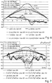
- the first derivative of the enveloping curves which is shown in each case, is also formed here.
- the first derivative for the peak current of 38 A is shown with a solid line
- the first derivative for the peak current of 42 A is shown with a solid line
- the first derivative for the peak current of 50 A is shown with thin lines
- the first derivative for the peak current of 64 A is shown in thick lines. From the Fig. 6 it can be seen that in the aforementioned time window between 3 ms and 5 ms after the zero crossing of the enveloping curve, the first derivative of the peak current of 50 A remains approximately the same with small fluctuations. With a peak current of 64 A and a strong saturation, the corresponding thick dashed curve increases significantly, while it continues to decrease with the two smaller peak currents.
- the respective second derivative is then shown, in the same way for the courses with different peak currents as for the first derivative in Fig. 6 , It can be seen here that in the time window shown between 3 ms and 5 ms after the zero crossing of the enveloping curve, the thinly dashed curve of the second derivative at a peak current of 50 A slightly exceeds the indicated limit value of 1.0 A / ms 2 , and twice. This also enables the onset of saturation and thus a good control point to be recognized. Furthermore, here in the Fig. 7 can still be seen that the second derivative for the next smaller peak current of 42 A remains significantly below this limit in this time window. The thick dashed second derivative of the curve at a peak current of 64 A is many times higher. In this way, the additional condition can also be defined in a very general way that the transformer current is regulated in such a way that the second derivative in this time window should be between 1.0 and 1.5 or between 1.0 and 2 A / ms 2 .
Abstract
Zur induktiven Energieübertragung zwischen einer Übertragerspule als Induktionsheizspule und einer Empfängerspule mittels induktiver Resonanz-Übertrager bei einem Induktionskochfeld ist die Übertragerspule Teil eines Übertrager-Schwingkreises ist und die Empfängerspule ist Teil eines Empfänger-Schwingkreises. Das magnetische Feld in der Spulen wird jeweils von an den abgewandten Seiten angeordnet Ferriten geführt wird. Unterhalb der Ferrite der Übertragerspule ist ein Tragblech für die Induktionsheizspule angeordnet. Der Strom durch die Übertragerspule wird überwacht und derart abgeregelt, dass die Ferrite der Übertragerspule im Bereich einer einsetzenden Sättigung sind und die in den Ferriten induzierten magnetischen Flüsse ein mögliches Maximum entsprechend der Sättigung erreichen. Dazu wird der Strom durch die Übertragerspule derart abgeregelt, dass er maximal 10% über demjenigen Sättigungsstrom liegt, bei dem in den Ferriten Sättigung einsetzt.For inductive energy transmission between a transmitter coil as an induction heating coil and a receiver coil by means of an inductive resonance transmitter in an induction hob, the transmitter coil is part of a transmitter resonant circuit and the receiver coil is part of a receiver resonant circuit. The magnetic field in the coils is guided by ferrites arranged on the opposite sides. A support plate for the induction heating coil is arranged below the ferrites of the transmitter coil. The current through the transmitter coil is monitored and regulated in such a way that the ferrites of the transmitter coil are in the region of an onset of saturation and the magnetic fluxes induced in the ferrites reach a possible maximum corresponding to the saturation. For this purpose, the current through the transmitter coil is regulated in such a way that it is at most 10% above the saturation current at which saturation begins in the ferrites.
Description
Die Erfindung betrifft ein Verfahren zur induktiven Energieübertragung zwischen einer Übertragerspule und einer Empfängerspule sowie eine Vorrichtung, mit der dieses Verfahren durchgeführt werden kann.The invention relates to a method for inductive energy transmission between a transmitter coil and a receiver coil and a device with which this method can be carried out.
Induktive Energieübertragung wird im Bereich der Technik immer wichtiger und ist beispielsweise aus der
Der Erfindung liegt die Aufgabe zugrunde, ein eingangs genanntes Verfahren sowie eine zu dessen Durchführung geeignete Vorrichtung zu schaffen, mit denen Probleme des Standes der Technik gelöst werden können und es insbesondere möglich ist, eine induktive Energieübertragung möglichst gut zu erreichen, insbesondere auch bei Verwendung eines Induktionskochfelds als Vorrichtung zur Energieübertragung.The invention has for its object to provide a method mentioned at the outset and a device suitable for carrying it out, with which problems of the prior art can be solved and in particular it is possible to achieve inductive energy transfer as well as possible, in particular also when using a Induction hob as a device for energy transmission.
Gelöst wird diese Aufgabe durch ein Verfahren mit den Merkmalen des Anspruchs 1 sowie durch eine Vorrichtung mit den Merkmalen des Anspruchs 15. Vorteilhafte sowie bevorzugte Ausgestaltungen der Erfindung sind Gegenstand der weiteren Ansprüche und werden im Folgenden näher erläutert. Dabei werden manche der Merkmale nur für das Verfahren oder nur für die Vorrichtung erläutert. Sie sollen jedoch unabhängig davon sowohl für das Verfahren als auch für die Vorrichtung selbständig und unabhängig voneinander gelten können. Der Wortlaut der Ansprüche wird durch ausdrückliche Bezugnahme zum Inhalt der Beschreibung gemacht.This object is achieved by a method having the features of
Bei dem Verfahren werden eine Übertragerspule und eine Empfängerspule verwendet, um induktiv Energie zu übertragen. Vorteilhaft erfolgt dies mittels induktiver Resonanz-Übertrager. Die Übertragerspule ist Teil eines Übertrager-Schwingkreises, und die Empfängerspule ist Teil eines Empfänger-Schwingkreises. Beide Schwingkreise weisen bevorzugt noch entsprechend dimensionierte Kapazitäten bzw. Kondensatoren auf. Die Energie wird dabei induktiv von dem Übertrager-Schwingkreis zu dem Empfänger-Schwingkreis übertragen. Dies kann bevorzugt entsprechend dem vorgenannten beim WPC-Konsortium erarbeiteten Standard erfolgen, muss es aber nicht.The method uses a transmitter coil and a receiver coil to transmit energy inductively. This is advantageously done by means of inductive resonance transmitters. The transmitter coil is part of a transmitter resonant circuit and the receiver coil is part of a receiver resonant circuit. Both resonant circuits preferably also have appropriately dimensioned capacitors or capacitors. The energy is transmitted inductively from the transmitter resonant circuit to the receiver resonant circuit. This can be preferred according to the standard developed by the WPC consortium, but it does not have to be.
Das magnetische Feld in der Übertragerspule und/oder in der Empfängerspule wird von Ferriten geführt, wobei die Ferrite auf der jeweils von der Gegenspule abgewandten Seite angeordnet sind. Deren mögliche nähere Ausgestaltung wird nachfolgend noch im Detail erläutert. Des Weiteren sind an der Übertragerspule und/oder an der Empfängerspule an einer von der jeweiligen Gegenspule abgewandten Seite Metallteile angeordnet, vorteilhaft als flächig ausgebildete Metallteile. Dies können beispielsweise Tragevorrichtungen oder auch Schirmvorrichtungen für die jeweilige Spule sein. Bei der Verwendung eines Induktionskochfelds als erfindungsgemäße Vorrichtung kann dies vorzugsweise ein großflächiges Tragblech aus Aluminium sein, auf dem die mindestens eine Übertragerspule angeordnet ist. Es dient der mechanischen Halterung der Übertragerspule bzw. einer Induktionsheizspule sowie der Abschirmung von darunter angeordneten Bauteilen und Baugruppen gegen magnetische Felder.The magnetic field in the transmitter coil and / or in the receiver coil is guided by ferrites, the ferrites being arranged on the side facing away from the opposite coil. Their possible more detailed configuration is explained in detail below. Furthermore, metal parts are arranged on the transmitter coil and / or on the receiver coil on a side facing away from the respective counter coil, advantageously as flat metal parts. These can be, for example, carrying devices or shielding devices for the respective coil. When using an induction hob as the device according to the invention, this can preferably be a large-area support plate made of aluminum, on which the at least one transmitter coil is arranged. It is used to mechanically hold the transmitter coil or an induction heating coil and to shield components and assemblies arranged underneath against magnetic fields.
Bei dem Verfahren wird der Strom durch die Übertragerspule überwacht. Er wird derart abgeregelt oder begrenzt, dass die Ferrite im Bereich einer einsetzenden Sättigung sind bzw. in den Ferriten induzierte magnetische Flüsse ein mögliches Maximum erreichen, aber nach Möglichkeit kein noch höherer Strom durch die Übertragerspule fließt. Dieses mögliche Maximum entspricht dann der Sättigung. Sättigung kann in der Übertrager- und/oder in der Empfängerspule eintreten. Eine sogenannte Sättigungsinduktion von Ferriten nimmt außerdem mit deren zunehmender Temperatur ab, sie ist also auch temperaturabhängig. Das bedeutet, dass die Sättigung in den Ferriten schneller bzw. bei geringeren Strömen auftritt je wärmer diese werden. Im kalten Zustand der Ferrite kann somit ein höherer Strom durch die Übertragerspule verwendet werden und damit mehr Energie übertragen. Dies gilt insbesondere, wenn ein Regler auf den Einsatzpunkt der Sättigung regelt. Der Strom durch die Übertragerspule wird dabei derart abgeregelt oder derart begrenzt, dass er maximal 5 % bis 10 % über demjenigen Sättigungsstrom liegt, bei dem in den Ferriten die genannte Sättigung eintritt. Der Strom durch die Übertragerspule kann also etwas größer sein, aber nicht viel, vorteilhaft eben nur 5 % bis 10 % größer sein. Besonders vorteilhaft wird der Strom durch die Übertragerspule sogar auf maximal 2 % über dem Sättigungsstrom begrenzt, so dass das Verfahren nahezu an der Sättigungsgrenze arbeitet.In the method, the current through the transformer coil is monitored. It is regulated or limited in such a way that the ferrites are in the region of onset of saturation or magnetic fluxes induced in the ferrites reach a possible maximum, but if possible no higher current flows through the transmitter coil. This possible maximum then corresponds to saturation. Saturation can occur in the transmitter and / or in the receiver coil. So-called saturation induction of ferrites also decreases with increasing temperature, so it is also temperature-dependent. This means that the saturation in the ferrites occurs faster or with lower currents the warmer they become. When the ferrites are cold, a higher current can be used through the transmitter coil and thus more energy can be transferred. This applies in particular if a controller regulates the point of application of saturation. The current through the transformer coil is regulated or limited in such a way that it is at most 5% to 10% above the saturation current at which the said saturation occurs in the ferrites. The current through the transformer coil can therefore be somewhat larger, but not much, advantageously only 5% to 10% larger. The current through the transformer coil is particularly advantageously even limited to a maximum of 2% above the saturation current, so that the method works almost at the saturation limit.
Das Problem, das zur Entstehung der Erfindung geführt hat, besteht nämlich darin, dass dann, wenn die Ferrite gesättigt sind, ein Teil des Magnetfelds in die genannten benachbarten Metallteile eindringen kann und dort zum einen für eine ungewünschte Erwärmung sorgen kann. Zum anderen und hauptsächlich geht diese Energie natürlich der Energieübertragung verloren, so dass die Effizienz der Energieübertragung deutlich negativ beeinträchtigt wird. Schließlich ist es auch noch möglich, dass eine Leistungsversorgung der Übertragerspule durch zu hohe Ströme zu stark belastet oder möglicherweise sogar beschädigt wird.The problem that led to the development of the invention is that when the ferrites are saturated, part of the magnetic field can penetrate into the adjacent metal parts mentioned and, on the one hand, can provide undesired heating there. On the other hand and mainly this energy is of course lost in energy transmission, so that the efficiency of energy transmission is significantly adversely affected. Finally is it is also possible that a power supply to the transmitter coil is too heavily loaded or possibly even damaged by excessive currents.
In vorteilhafter Ausgestaltung der Erfindung ist die Übertragerspule bei Durchführen des Verfahrens mit einem Induktionskochfeld eine Induktionsheizspule des Induktionskochfelds. Besonders vorteilhaft wird das Verfahren nur mit einer einzigen Induktionsheizspule durchgeführt, wobei diese Induktionsheizspulen und insbesondere ihre Leistungsansteuerung speziell dafür ausgebildet sind.In an advantageous embodiment of the invention, when the method is carried out with an induction hob, the transmitter coil is an induction heating coil of the induction hob. The method is particularly advantageously carried out using only a single induction heating coil, these induction heating coils and in particular their power control being specially designed for this purpose.
Vorteilhaft kann vorgesehen sein, dass die Übertragerspule und der Übertrager-Schwingkreis unter einer Tischplatte angeordnet sind, die als übliche Tischplatte als Möbel in einem Haushalt dienen kann. Eine solche Tischplatte, vorteilhaft bestehend aus Holz, Stein oder anderen nichtmagnetischen und nicht-metallischen Materialien, kann eine Dicke von maximal 60 mm aufweisen. Vorteilhaft liegt eine Dicke im Bereich zwischen 5 mm und 20 mm oder sogar 40 mm. Selbst wenn hier eine Tischplatte vorgesehen ist, so ist die Vorrichtung im Sinne dieser Erfindung doch zumindest auch ein Kochfeld, da mit der Induktionsheizspule eben auch gekocht werden kann. Hierfür kann möglicherweise auf die Tischplatte eine separate Unterlage für ein Kochgefäß aufgelegt werden wegen Hitzeproblemen, was an sich aber kein Problem darstellt. Die genannte Tischplatte ersetzt dann eine sonstige Kochfeldplatte, die üblicherweise aus Glaskeramik besteht. Ein solches Induktionskochfeld mit einer Tischplatte und mindestens einer Induktionsheizspule darunter kann dann erheblich größer ausgebildet sein als ein übliches Induktionskochfeld. Die mindestens eine Induktionsheizspule kann auch beweglich darunter angeordnet sein, so dass sie an unterschiedliche Positionen gebracht werden kann. Wie dies im Detail zu realisieren ist, kennt der Fachmann aus dem Stand der Technik und braucht hier nicht näher erläutert zu werden.It can advantageously be provided that the transmitter coil and the transmitter resonant circuit are arranged under a table top, which can serve as a conventional table top as furniture in a household. Such a table top, advantageously consisting of wood, stone or other non-magnetic and non-metallic materials, can have a maximum thickness of 60 mm. A thickness is advantageously in the range between 5 mm and 20 mm or even 40 mm. Even if a table top is provided here, the device in the sense of this invention is at least also a hob, since the induction heating coil can also be used for cooking. For this purpose, a separate base for a cooking vessel can possibly be placed on the table top due to heat problems, but this is not a problem in itself. The table top mentioned then replaces another hob, which usually consists of glass ceramic. Such an induction hob with a table top and at least one induction heating coil underneath can then be made considerably larger than a conventional induction hob. The at least one induction heating coil can also be arranged movably underneath so that it can be brought to different positions. The person skilled in the art knows how to implement this in detail from the prior art and need not be explained in more detail here.
In Ausgestaltung der Erfindung ist an der Übertragerspule an einer von der Empfängerspule abgewandten Seite ein flächiges Metallblech als vorgenanntes Metallteil angeordnet. Dieses flächige Metallblech weist eine Fläche auf, die mindestens 70 % der Fläche der Übertragerspule beträgt, vorteilhaft mindestens so groß ist wie diese Übertragerspule. Sie kann dazu dienen, der Übertragerspule Festigkeit zu verleihen und vor allem auch eine Abschirmung nach unten sicherzustellen. Ein Abstand zwischen dem Metallblech und der Übertragerspule kann maximal 50 mm betragen, vorteilhaft maximal 10 mm bis 20 mm. Dies ist auf Spulenwindungen der Übertragerspule bezogen. Das flächige Metallblech kann Durchbrüche und Öffnungen aufweisen, die ein Einrasten bzw. Fixieren von Übertragerspulen und Kabeldurchführungen oder eine Kühlung erlauben. Zur Schirmung wird vorzugsweise ein elektrisch gut leitfähiges Metall mit hohem Aluminium- oder Kupferanteil verwendet.In an embodiment of the invention, a flat metal sheet is arranged on the transmitter coil on a side facing away from the receiver coil as the aforementioned metal part. This flat metal sheet has an area which is at least 70% of the area of the transmitter coil, advantageously at least as large as this transmitter coil. It can serve to give strength to the transformer coil and, above all, to ensure shielding from below. A distance between the metal sheet and the transmitter coil can be a maximum of 50 mm, advantageously a maximum of 10 mm to 20 mm. This is related to coil turns of the transmitter coil. The flat metal sheet can have openings and openings which allow the transmitter coils and cable feedthroughs to be latched or fixed in place or allow cooling. An electrically highly conductive metal with a high aluminum or copper content is preferably used for shielding.
Bei einer vorgenannten Ausgestaltung der Erfindung mit einem flächigen Metallblech ist vorteilhaft vorgesehen, dass die Ferrite zwischen dem Metallblech und der Übertragerspule angeordnet sind. Ihre Dicke liegt üblicherweise im Bereich zwischen 4 mm und 10 mm, so dass auch die vorgenannte vorteilhafte Abstandsbedingung eingehalten werden kann.In a previously mentioned embodiment of the invention with a flat metal sheet, it is advantageously provided that the ferrites are arranged between the metal sheet and the transmission coil. Their thickness is usually in the range between 4 mm and 10 mm, so that the aforementioned advantageous spacing conditions can also be met.
Die genannten Ferrite sind vorteilhaft länglich und flach ausgebildet. Ihre Breite kann das Zweifache bis Zehnfache der Dicke betragen. Ihre Länge kann das Dreifache bis Zehnfache ihrer Breite betragen. Bevorzugt sind die Ferrite derart an der Übertragerspule angeordnet, dass sie in deren Mittelbereich weisen, insbesondere auf einen geometrischen Mittelpunkt. Es können zwischen zwei und zehn Ferrite vorgesehen sein. Vorteilhaft sind sie identisch ausgebildet, dies ist aber nicht zwingend.The ferrites mentioned are advantageously elongated and flat. Their width can be twice to ten times the thickness. Their length can be three to ten times their width. The ferrites are preferably arranged on the transmitter coil in such a way that they point in their central region, in particular to a geometric center. Between two and ten ferrites can be provided. They are advantageously identical, but this is not mandatory.
Um ein Einsetzen der Sättigung der Ferrite zu erkennen, gibt es mehrere Möglichkeiten. In einer ersten grundsätzlichen Möglichkeit kann die erste Ableitung einer einhüllenden Kurve des Stroms durch die Übertragerspule berechnet werden oder ermittelt werden. Als einhüllende Kurve wird der Verlauf der positiven Spitzenwerte des Stroms durch die Übertragerspule verstanden. Dieser Verlauf kann beispielsweise durch einen gleitenden Spitzenwertdetektor ermittelt werden, so dass sowohl der Anstieg des Spitzenwerts bei steigender Netzspannung als auch die Abnahme des Spitzenwerts bei fallender Netzspannung beobachtet werden kann. Diese erste Ableitung wird durch zwei Tiefpässe geglättet, die unterschiedliche Zeitkonstanten aufweisen. Eine Zeitkonstante des zweiten Tiefpasses beträgt dabei das Fünffache bis Zwanzigfache einer Zeitkonstanten des ersten Tiefpasses, insbesondere etwa das Zehnfache. Bevorzugt kann vorgesehen sein, dass die Zeitkonstante des ersten Tiefpasses der 1,0-fachen bis fünffachen Periodendauer des Stroms durch die Übertragerspule entspricht. Besonders bevorzugt kann sie der zweifachen Periodendauer des Stroms durch die Übertragerspule entsprechen.There are several ways to detect the onset of ferrite saturation. In a first basic possibility, the first derivative of an envelope curve of the current through the transmitter coil can be calculated or ascertained. The envelope curve is understood to be the course of the positive peak values of the current through the transmitter coil. This curve can be determined, for example, by means of a sliding peak value detector, so that both the increase in the peak value when the mains voltage rises and the decrease in the peak value when the mains voltage falls. This first derivative is smoothed by two low-pass filters that have different time constants. A time constant of the second low pass is five to twenty times a time constant of the first low pass, in particular approximately ten times. It can preferably be provided that the time constant of the first low pass corresponds to 1.0 times to five times the period of the current through the transmitter coil. It can particularly preferably correspond to twice the period of the current through the transformer coil.
Hier ist es möglich, ein Einsetzen der Sättigung der Ferrite dann zu erkennen, wenn das Signal nach dem ersten Tiefpass der einhüllenden Kurve des Stroms durch die Übertragerspule für eine Dauer von mindestens 0,3 ms bei einer Schaltfrequenz zwischen 20 kHz und 60 kHz des Stroms durch die Übertragerspule nicht abfällt, wobei vorzugsweise nur ein Zeitfenster zwischen 2,5 ms und 5 ms nach dem Nulldurchgang der Netzspannung, zumeist 50 Hz oder 60 Hz, betrachtet wird. Innerhalb dieses Zeitfensters darf das Signal nach dem ersten Tiefpass also für eine bestimmte Dauer nicht abfallen. Besonders vorteilhaft sollte das Signal nach dem ersten Tiefpass in diesem Zeitfenster ansteigen, um dann sicher ein Einsetzen der Sättigung der Ferrite zu erkennen. Durch dieses Ermitteln eines Signalverlaufs nach zwei Tiefpässen wird der Rechenaufwand verringert.Here it is possible to detect the onset of the saturation of the ferrites when the signal after the first low pass of the envelope curve of the current through the transmitter coil for a period of at least 0.3 ms at a switching frequency between 20 kHz and 60 kHz of the current does not drop through the transformer coil, preferably only a time window between 2.5 ms and 5 ms after the zero crossing of the mains voltage, usually 50 Hz or 60 Hz, is considered. Within this time window, the signal must not fall off for a certain period after the first low pass. The signal after the first low-pass filter should rise particularly advantageously in this time window in order to then reliably detect the onset of the saturation of the ferrites. This calculation of a signal curve after two low-pass filters reduces the computing effort.
Eine Sättigung der Ferrite tritt grundsätzlich bei großen Strömen auf, d.h. sie tritt vorzugsweise um das Maximum einer sinusförmigen Netzspannung auf. Bei 50Hz-Netzen liegt das Maximum bei 5,0ms nach dem Nulldurchgang, bei 60Hz-Netzen bereits bei 4,17msec. Bei einer idealen linearen Last fällt die erste Ableitung des Strom gemäß einer Kosinusfunktion von +1 bis -1 eines Maximalwertes, in der Realität kann sich ein vom Kosinus abweichendes Verhalten einstellen, bei dem dennoch die erste Ableitung kontinuierlich im Verlauf der Netzhalbwelle abnimmt. Den Bereich um die Nulldurchgänge nimmt man vorzugsweise aus der Analyse aus, da eine Sättigung zuerst bei hohen Spannungen auftritt, und Einregelvorgänge sowie Nichtlinearitäten bei kleinen Stromwerten auch eine Ursache für kurzzeitiges Ansteigen der ersten Ableitung sein können. So ergeben sich vorteilhaft die vorgenannten 2,5 ms.Saturation of the ferrites basically occurs with large currents, i.e. it preferably occurs around the maximum of a sinusoidal mains voltage. With 50 Hz networks the maximum is 5.0 ms after the zero crossing, with 60 Hz networks already with 4.17 msec. With an ideal linear load, the first derivative of the current falls according to a cosine function from +1 to -1 of a maximum value; in reality, a behavior deviating from the cosine can occur, in which the first derivative nevertheless decreases continuously in the course of the network half-wave. The area around the zero crossings is preferably excluded from the analysis, since saturation occurs first at high voltages, and adjustment processes and non-linearities at small current values can also be a cause for a brief rise in the first derivative. This advantageously results in the aforementioned 2.5 ms.
Als zweite Möglichkeit in Abwandlung dieser ersten Möglichkeit kann vorgesehen sein, dass ein Einsetzen der Sättigung der Ferrite dann erkannt wird, wenn das Signal nach dem ersten Tiefpass das Signal nach dem zweiten Tiefpass durchbricht und mindestens 0,2 ms lang größer bleibt. Vorteilhaft bleibt das Signal nicht nur mindestens 0,2 ms lang größer, sondern sogar 0,5 ms lang. Dies bedeutet, dass sich die jeweiligen Verläufe der Signale nach dem ersten Tiefpass und nach dem zweiten Tiefpass im zeitlichen Bereich zwischen Nulldurchgang und Maximum der einhüllenden Kurve des Stroms durch die Übertragerspule schneiden, d.h. der fallende Trend der ersten Ableitung des Stroms hat sich umgekehrt, und somit wird das Einsetzen der Sättigung erkannt.As a second possibility, as a modification of this first possibility, it can be provided that the onset of saturation of the ferrites is recognized when the signal after the first low pass breaks through the signal after the second low pass and remains longer for at least 0.2 ms. The signal advantageously not only remains larger for at least 0.2 ms, but even 0.5 ms. This means that the respective courses of the signals after the first low pass and after the second low pass intersect in the time range between zero crossing and maximum of the envelope curve of the current through the transmitter coil, i.e. the falling trend of the first derivative of the current has reversed, and thus the onset of saturation is recognized.
Als dritte grundsätzliche Möglichkeit kann nach dem Bilden der ersten Ableitung der einhüllenden Kurve des Stroms durch die Übertragerspule eine einsetzende Sättigung der Ferrite dann erkannt werden, wenn sich in einem Zeitfenster von 2,5 ms bis 5 ms nach einem Nulldurchgang der Netzspannung sich die mit einem Tiefpass geglättete erste Ableitung oder der gleitende Mittelwert der ersten Ableitung der einhüllenden Kurve des Stroms in etwa konstant oder steigend verhält. Dabei kann sie sich maximal um 10 % nach oben oder nach unten verändern, vorzugsweise um maximal 7 %. Der Wert der ersten Ableitung sollte während einer Zeitspanne von mindestens 0,3 ms, vorzugsweise von 0,5 ms bis 1 ms, nicht kleiner geworden sein, insbesondere kann ein Grenzwert eben bei einem Anstieg von 10 % oder 7 % liegen. Hier wird also eine einsetzende Sättigung dann erkannt, wenn sich in dem genannten Zeitfenster die erste Ableitung der einhüllenden Kurve quasi konstant oder nur leicht steigend verhält.As a third basic possibility, after the first derivative of the enveloping curve of the current through the transmitter coil has been formed, the onset of saturation of the ferrites can be recognized if there is a change in a time window from 2.5 ms to 5 ms after a zero crossing of the mains voltage Low pass smoothed first derivative or the moving average of the first derivative of the envelope curve of the current behaves approximately constant or increasing. It can change a maximum of 10% upwards or downwards, preferably by a maximum of 7%. The value of the first derivative should not have decreased over a period of at least 0.3 ms, preferably from 0.5 ms to 1 ms, in particular a limit value can be an increase of 10% or 7%. Here, an onset of saturation is recognized when the first derivative of the enveloping curve behaves in a quasi-constant or only slightly increasing manner in the time window mentioned.
Hier kann in weiterer Ausgestaltung vorgesehen sein, dass auch die zweite Ableitung der einhüllenden Kurve des Stroms durch die Übertragerspule gebildet wird. Eine einsetzende Sättigung wird dann erkannt, wenn in dem genannten Zeitfenster zwischen 2,5 ms und 5 ms nach dem Nulldurchgang der einhüllenden Kurve des Stroms die zweite Ableitung mindestens 1,0 A/ms2 beträgt. In diesem Fall wird also überwacht, wie stark die erste Ableitung sozusagen ansteigt.In a further embodiment it can be provided here that the second derivative of the envelope curve of the current is also formed by the transmitter coil. An onset of saturation is detected if the second derivative at least occurs in the time window between 2.5 ms and 5 ms after the zero crossing of the enveloping curve of the current Is 1.0 A / ms 2 . In this case, the extent to which the first derivative rises, so to speak, is monitored.
Als vierte grundsätzliche Möglichkeit kann in einem vorausgehenden Schritt eine Referenzkurve für die einhüllende Kurve des Stroms durch die Übertragerspule aufgenommen werden. Dies kann dann erfolgen, wenn 50 % der maximal übertragbaren Energie übertragen werden, und zwar höchstens 50 % oder sogar genau 50 %. Es erfolgt jedenfalls in einem Zustand, in dem die Sättigung noch weit entfernt ist. Bei der anschließenden Überwachung des Stroms durch die Übertragerspule wird dessen einhüllende Kurve mit der Referenzkurve verglichen. Dabei werden vorteilhaft die beiden Kurvenverläufe normiert bzw. aufeinander abgestimmt für eine Vergleichbarkeit. Eine einsetzende Sättigung wird dann erkannt, wenn die einhüllende Kurve des Stroms durch die Übertragerspule mindestens 10 %, vorzugsweise mindestens 20 %, größer ist als die genannte Referenzkurve. Vorzugsweise wird die Sättigung dann erkannt, wenn die einhüllende Kurve mindestens 20 % größer wird als die Referenzkurve bzw. diese entsprechend übersteigt.As a fourth basic possibility, a reference curve for the envelope curve of the current through the transmitter coil can be recorded in a preceding step. This can take place when 50% of the maximum transferable energy is transmitted, namely at most 50% or even exactly 50%. In any case, it takes place in a state in which the saturation is still far away. During the subsequent monitoring of the current through the transmitter coil, its envelope curve is compared with the reference curve. The two curves are advantageously standardized or matched to one another for comparability. An onset of saturation is recognized when the envelope curve of the current through the transmitter coil is at least 10%, preferably at least 20%, larger than the reference curve mentioned. The saturation is preferably detected when the enveloping curve is at least 20% larger than the reference curve or exceeds it accordingly.
Als weitere Abwandlung ähnlich dieser zweiten Möglichkeit kann es vorgesehen sein, dass eine einsetzende Sättigung dann erkannt wird, wenn die erste Ableitung des Stroms durch die Übertragerspule in einem Zeitfenster zwischen einem Zehntel und einem Viertel der Periodendauer des Stroms durch die Übertragerspule während eines abfallenden Bereichs oder in einem abfallenden Bereich kurzzeitig erneut ansteigt. Dieser Anstieg erfolgt vorteilhaft für mindestens 1 µs und/oder um mindestens 10 % der Signalhöhe zu diesem Zeitpunkt. Unter Umständen kann der Anstieg auch nur mindestens 5 % sein.As a further modification similar to this second possibility, it can be provided that an onset saturation is recognized when the first derivative of the current through the transmitter coil occurs in a time window between a tenth and a quarter of the period of the current through the transmitter coil during a falling range or briefly rises again in a falling area. This increase advantageously takes place for at least 1 μs and / or at least 10% of the signal level at this point in time. Under certain circumstances, the increase can only be at least 5%.
Alternativ zur Auswertung der Einhüllenden des Stroms durch die Übertragerspule können die gleichen Methoden auch auf die Auswertung der zugeführten Ströme im Zwischenkreis angewandt werden, siehe den Strom iDC in
Die Vorrichtung weist also neben der vorgenannten Übertragerspule bzw. dem Übertrager-Schwingkreis vor allem auch Mittel zum Überwachen bzw. Ermitteln des Stroms durch die Übertragerspule auf. Des Weiteren weist sie Mittel zum Ermitteln der ersten und ggf. auch der zweiten Ableitung dieses Stroms auf. Zusätzlich weist sie an der Übertragerspule die Ferrite auf und darunter ein Tragblech als Metallteil. Vorteilhaft ist die Vorrichtung ein Induktionskochfeld mit mehreren Induktionsheizspulen, von denen mindestens eine ausgebildet ist samt Ansteuerung, das vorgenannte Verfahren durchzuführen. Sie wird nachfolgend noch im Detail erläutert. Diese und weitere Merkmale gehen außer aus den Ansprüchen auch aus der Beschreibung und den Zeichnungen hervor, wobei die einzelnen Merkmale jeweils für sich allein oder zu mehreren in Form von Unterkombinationen bei einer Ausführungsform der Erfindung und auf anderen Gebieten verwirklicht sein und vorteilhafte sowie für sich schutzfähige Ausführungen darstellen können, für die hier Schutz beansprucht wird. Die Unterteilung der Anmeldung in einzelnen Abschnitte sowie Zwischen-Überschriften beschränken die unter diesen gemachten Aussagen nicht in ihrer Allgemeingültigkeit.In addition to the aforementioned transmitter coil or the transmitter resonant circuit, the device therefore also has means for monitoring or determining the current through the transmitter coil. Furthermore, it has means for determining the first and possibly also the second derivative of this current. In addition, it has the ferrites on the transmitter coil and underneath a support plate as a metal part. The device is advantageously an induction hob with a plurality of induction heating coils, at least one of which is designed, including the control, to carry out the aforementioned method. It is explained in detail below. These and other features emerge from the claims and also from the description and the drawings, the individual features being realized individually or in groups in the form of sub-combinations in one embodiment of the invention and in other fields and being advantageous and protectable per se Can represent versions for which protection is claimed here. The division of the application into individual sections and subheadings do not limit the general validity of the statements made under these.
Ausführungsbeispiele der Erfindung sind in den Zeichnungen schematisch dargestellt und werden im Folgenden näher erläutert. Dabei zeigen:
- Fig. 1
- eine erfindungsgemäße Vorrichtung als Induktionskochfeld zur Durchführung des Verfahrens,
- Fig. 2
- der Verlauf eines Stroms durch die Übertragerspule und dessen abgeleitete Steigung im Netzspannungsmaximum,
- Fig. 3
- der Verlauf der einhüllenden Kurve des Stroms durch die Übertragerspule während einer Netzhalbwelle mit Verläufen der ersten Ableitung und deren zweimaliger Glättung durch unterschiedliche Tiefpässe, wenn noch keine Sättigung in den Ferriten der Übertragerspule aufgetreten ist,
- Fig. 4 und 5
- jeweils das Diagramm aus
Fig. 3 mit einsetzender Sättigung und mit starker Sättigung, - Fig. 6
- eine Darstellung der einhüllenden Kurve des Übertragerstroms samt seiner ersten Ableitung nach der Zeit für verschiedene Sättigungsgrade und
- Fig. 7
- eine Darstellung ähnlich
Fig. 6 mit der Darstellung der jeweils zweiten Ableitung.
- Fig. 1
- a device according to the invention as an induction hob for carrying out the method,
- Fig. 2
- the course of a current through the transformer coil and its derived slope in the mains voltage maximum,
- Fig. 3
- the course of the enveloping curve of the current through the transmitter coil during a network half-wave with courses of the first derivative and its smoothing twice by means of different low-pass filters if no saturation has yet occurred in the ferrites of the transmitter coil,
- 4 and 5
- the diagram
Fig. 3 with onset of saturation and with strong saturation, - Fig. 6
- a representation of the envelope curve of the transformer current including its first derivative over time for different degrees of saturation and
- Fig. 7
- a representation similar
Fig. 6 with the representation of the second derivative.
In der
Der Übertrager-Schwingkreis 13 weist eine Übertragerspule 15 auf, welche hier eine Induktionsheizspule ist. Sie ist vorteilhaft aus HF-Spulenlitze in einer Ebene spiralig aufgewickelt. Unterhalb der Übertragerspule 15 sind Ferrite 16 angeordnet, und zwar in Stabform und in radialer Richtung verteilt. Es können sechs bis zehn Ferrite 16 sein. Sie sind vorteilhaft an der Unterseite der Übertragerspule 15 befestigt, beispielsweise angeklebt. Alternativ können sie in einer Kunststoffhalterung daran gehalten sein. Dies ist aus dem Stand der Technik bekannt für den Aufbau von Induktionskochfeldern bzw. Induktionsheizspulen. Zu dem Übertrager-Schwingkreis 13 gehören eigentlich noch die beiden Übertragerkondensatoren 21a und 21b, die ganz rechts im Schaltbild dargestellt sind.The transformer
Die Übertragerspule 15 soll auf einem flächigen Tragblech 18 aufliegen. Dieses besteht vorteilhaft aus Aluminium, wichtig ist, dass es elektrisch niederohmig ist. Alternative Werkstoffe sind Kupfer oder ggf. eine Silberlegierung. Das Tragblech 18, das auch aus der vorgenannten Offenlegungsschrift bekannt ist, weist zum einen eine Tragfunktion für die Übertragerspule 15 auf, möglicherweise auch noch für weitere Induktionsheizspulen des Induktionskochfelds in Form der Vorrichtung 11. Des Weiteren schirmt das Tragblech 18 darunterliegende elektronische und elektrische Bauteile gegen das Magnetfeld der darauf angeordneten Spulen ab. Schließlich kann das Tragblech 18 auch noch Wärmeleitfunktion und somit Kühlfunktion aufweisen sowie mit Öffnungen oder Aussparungen zur Befestigung oder für Kabeldurchführungen versehen sein.The
Oberhalb der Übertragerspule 15 ist eben die Empfängerspule 25 des Empfänger-Schwingkreises 23 vorgesehen. Vorteilhaft wird sie in einem flachen Gehäuse oder als flaches Gerät auf eine Kochfeldplatte aufgelegt direkt oberhalb der Übertragerspule 15. Die Kochfeldplatte ist hier nicht dargestellt, aber leicht vorstellbar. Anstelle einer normalen Kochfeldplatte, die üblicherweise aus Glaskeramik besteht, kann es auch eine Tischplatte oder sonstige Ablageplatte sein mit einer vorgenannten Dicke und aus vorgenannten Materialien bestehend. Mit der Übertragerspule 15 kann auch wie mit einer normalen Induktionsheizspule gekocht werden mit induktivem Erwärmen eines darüber aufgestellten Kochgefäßes. In einem speziellen Betriebsverfahren kann eben auch eine induktive Energieübertragung erfolgen. Dabei kann die Empfängerspule 25 ähnlich ausgebildet sein wie die Übertragerspule 15, insbesondere in etwa die gleiche Größe bzw. Fläche und Form aufweisen. Auf ihrer Oberseite sind ebenso Ferrite 26 angeordnet und befestigt wie bei der Übertragerspule 15. Eine Schirmung ist auch oben im Empfänger denkbar, aber dort nicht zwingend. Der Empfänger-Schwingkreis 23 weist des Weiteren noch einen Empfängerkondensator 29 und eine Last 28 auf, an welche die induktive Energie letztlich übertragen werden soll bzw. die mit Energie versorgt werden soll. Diese Last 28 kann beispielsweise als ein Küchengerät in Form eines Standmixers, Wasserkochers odgl. vorliegen, die sozusagen oberhalb der Übertragerspule 15 auf die Abdeckung aufgestellt werden und die sozusagen kabellos mit Energie auf induktivem Weg versorgt werden. Da somit die Last 28 im Wesentlichen funktionieren soll wie ein sonstiger elektrischer Verbraucher entsprechend einem elektrischen Kleingerät oder einem elektrischem Küchengerät. Insofern sind der Übertrager-Schwingkreis 13 und der Empfänger-Schwingkreis 23 darauf auszulegen, des Weiteren ist eine Ansteuerung der Übertragerspule 15 auf entsprechendem Wege mit einer Frequenz von 50 Hz oder 60 Hz notwendig. Insofern entspricht die einhüllende Kurve des Übertragerstroms, die im Folgenden näher erläutert wird, dieser Frequenz von 50 Hz oder 60 Hz.Above the
Zur Ansteuerung der Übertragerspule 15 weist der Übertrager-Schwingkreis 13 ganz rechts unten einen ersten Übertragerkondensator 21a und darüber einen zweiten Übertragerkondensator 21b auf. Vor der Übertragerspule 15 kann ein Abgriff zur Erfassung des Übertragerstroms iHF als Strom durch die Übertragerspule vorgesehen sein. Links daneben sind zwei Transistoren 31a und 31b vorgesehen zur Ansteuerung des Übertrager-Schwingkreises 13. Über einen Zwischenkreiskondensator 34 sind sie auf übliche Art und Weise an einen Gleichrichter 33 angeschlossen, der wiederum mit einem Netzanschluss 35 verbunden ist. Dort kann der normale Wechselstrom iAC gemessen werden. Die Netzspannung UN am Netzanschluss 35 gibt eben die Frequenz von 50 Hz vor. Ein gleichgerichteter Strom iDC kann auch gemessen werdenTo control the
Der Wechselrichter mit den Transistoren 31a und 31b betreibt den Übertrager-Schwingkreis 13 mit einer Frequenz von 25 kHz, diese kann aber auch höher oder niedriger liegen. Während im Kochbetrieb die Übertragerspule 15 als Induktionsheizspule zumindest im kurzzeitigen Betrieb als Boost-Betrieb Energie mit einer Leistung bis zu 3,7 kW übertragen kann, die dann passiv in ein aufgesetztes Kochgefäß eingekoppelt wird zu dessen Erwärmung, kann im Betrieb mit induktiver Energieübertragung vorteilhaft eine Leistung bis zu 2,4 kW dauerhaft übertragen werden. Dies ist eine aktive Energieübertragung, da auf der Abnehmerseite ja auch ein Schwingkreis angeordnet ist, nämlich der Empfänger-Schwingkreis 23.The inverter with the
In den Ferriten 16 kann im Betrieb der induktiven Energieübertragung last- und betriebspunktabhängig eine Addition der magnetischen Flüsse von der Übertragerspule 15 und der Empfängerspule 25 auftreten. Dies kann dazu führen, dass die Ferrite 16 bei deutlich kleinerem Strom in der Übertragerspule 15 bereits in Sättigung kommen als dies üblicherweise beim induktiven Kochbetrieb auftreten würde, da der Phasenwinkel des Stroms in einem Kochgefäß nicht durch einen Resonanzkondensator verändert wird. Kommen diese Ferrite 16 in die Sättigung, dann induziert der sozusagen überschüssige magnetische Fluss, der von den Ferriten nicht mehr aufgenommen und nicht mehr geführt werden kann, Wirbelströme im metallischen Tragblech 18. Dies führt dazu, dass die wirksame Induktivität abnimmt, vor allem der Übertragerstrom iHF bei unveränderter Ansteuerung aber ansteigt. Dadurch nimmt zum einen der Wirkungsgrad ab, was aus Energieeffizienzgründen ungewünscht ist. Zum anderen kann durch zu hohe Ströme eine ungewollte Überlast oder Wärmeentwicklung in der Ansteuerung des Übertrager-Schwingkreises 13 entstehen, insbesondere in den Transistoren 31a und 31b. Des Weiteren ist die Sättigung von Ferriten temperaturabhängig. Üblicherweise nimmt eine Sättigungsgrenze mit zunehmender Temperatur ab, unter Umständen sogar signifikant, so dass durch einen längeren Betrieb mit höherer Temperatur ebenfalls schneller eine Sättigung auftritt, die erfindungsgemäß vermieden werden soll. Dies macht es auch schwierig, mit vorgegebenen Stromgrenzen zu arbeiten, um eine Sättigung in den Ferriten 16 zu vermeiden. Dieses Problem der Sättigung haben die Erfinder im Rahmen der Erfindung erkannt, wenn eben mit einer Induktionsheizspule eines Induktionskochfelds induktiv Energie übertragen werden soll in einen sozusagen aktiven Abnehmer bzw. Empfänger wie den Empfänger-Schwingkreis 23. Des Weiteren ist diese Sättigung der Ferrite 16 eben auch dadurch ein Problem, dass bei einem Induktionskochfeld als Vorrichtung 11 ein Tragblech 18 darunter vorgesehen ist.In the
Die Regelung des Übertragerstroms derart, dass keine oder nur eine geringfügige Sättigung auftritt, kann nun auf unterschiedliche Arten realisiert werden. Es ist jeweils eine Art Sättigungsregelung.The control of the transformer current in such a way that no or only a slight saturation occurs can now be implemented in different ways. It is a kind of saturation control.
In der
Die genannte Erfassung des Übertragerstroms iHF selbst samt Bilden seiner ersten Ableitung ist messtechnisch aber nicht ganz einfach, vor allem hinsichtlich einer geforderten Genauigkeit und der hohen zeitlichen Auflösung. Deswegen kann bei einer eingangs genannten ersten Möglichkeit einer Sättigungsregelung die einhüllende Kurve der Spitzenwerte bzw. Maximalwerte des Übertragerstroms betrachtet werden, wie sie in den
In der
In
In der
Des Weiteren ist aus der starken Sättigung der
Gemäß einer weiteren Möglichkeit einer Sättigungsregelung kann bei Betrachten der dünn strichlierten Kurve nach dem zweiten Tiefpass erkannt werden in dem vorgenannten Zeitfenster von 3 ms bis 5 ms nach einem Nulldurchgang der einhüllenden Kurve, dass diese Kurve nach dem zweiten Tiefpass noch einmal deutlich ansteigt, nämlich von etwa 6 A/ms auf 8 A/ms, also um deutlich mehr als die eingangs genannten 7 % bzw. 10 %. Die Dauer dieses Anstiegs beträgt etwas über 0,5 ms. Insbesondere liegt dieses Zeitfenster zwischen 3,5 ms und 4,1 ms.According to a further possibility of a saturation control, when looking at the thinly dashed curve after the second low-pass filter, it can be seen in the aforementioned time window from 3 ms to 5 ms after the envelope curve crosses zero that this curve rises again significantly after the second low-pass filter, namely from about 6 A / ms to 8 A / ms, i.e. significantly more than the 7% or 10% mentioned at the beginning. The duration of this increase is just over 0.5 ms. In particular, this time window is between 3.5 ms and 4.1 ms.
Bei den beiden Kurven nach den beiden Tiefpässen ist es auch möglich, um ein Rauschen bei den gemessenen Signalen zu vermeiden bzw. zu unterdrücken, dass in dem genannten Zeitfenster von 3 ms bis 5 ms eine Differenz zwischen den beiden Signalen, also zwischen dem dünn strichpunktierten Verlauf nach dem ersten Tiefpass und dem dick strichpunktierten Verlauf nach dem zweiten Tiefpass, aufintegriert wird, solange der Verlauf nach dem ersten Tiefpass größer ist als der andere. So erhält man ein robustes Signal, mit dem die einsetzende Sättigung oder die bereits deutlich eingesetzte Sättigung erkannt werden kann. Es kann dagegengeregelt werden, und zwar ist dies dann jeweils immer auch unabhängig davon, wann genau die temperaturabhängige Sättigung in den Ferriten 16 auftritt.In the case of the two curves after the two low-pass filters, it is also possible, in order to avoid or suppress noise in the measured signals, for a difference between the two signals, that is to say between the thin dash-dotted line, of 3 ms to 5 ms in the time window mentioned Course after the first low pass and the thick-dot-dash course after the second low pass is integrated as long as the course after the first low pass is greater than the other. This gives a robust signal with which the onset of saturation or the already clearly used saturation can be recognized. On the other hand, it can be regulated, and this is always independent of when exactly the temperature-dependent saturation occurs in the
In der
Ähnlich wie zuvor beschrieben wird auch hier die erste Ableitung der einhüllenden Kurven gebildet, die jeweils dargestellt ist. Die erste Ableitung für den Spitzenstrom von 38 A ist dünn durchgezogen dargestellt, die erste Ableitung für den Spitzenstrom von 42 A ist dick durchgezogen dargestellt, die erste Ableitung für den Spitzenstrom von 50 A ist dünn strichliert dargestellt und die erste Ableitung für den Spitzenstrom von 64 A ist dick strichliert dargestellt. Aus der
In der
Die nochmals weitere vorgenannte Möglichkeit der Aufnahme einer Referenzkurve für die einhüllende Kurve des Übertragerstroms mit deutlich unterhalb des Maximums liegender übertragener Energie und einem anschließenden Vergleich ist hier in den Figuren nicht dargestellt. Dies ist für den Fachmann aber leicht vorstellbar und realisierbar, weswegen auf eine separate Darstellung verzichtet werden kann. Die zuvor gegebene Beschreibung reicht hier zur Ausführung völlig aus.The yet further possibility of recording a reference curve for the envelope curve of the transmitter current with the transmitted energy lying clearly below the maximum and a subsequent comparison is not shown here in the figures. However, this is easily imaginable and realizable for the person skilled in the art, which is why a separate illustration can be dispensed with. The previously given description is sufficient here for execution.
Claims (15)
Priority Applications (1)
| Application Number | Priority Date | Filing Date | Title |
|---|---|---|---|
| PL19186440T PL3606284T3 (en) | 2018-07-30 | 2019-07-16 | Method and device for inductive energy transfer |
Applications Claiming Priority (1)
| Application Number | Priority Date | Filing Date | Title |
|---|---|---|---|
| DE102018212680.1A DE102018212680A1 (en) | 2018-07-30 | 2018-07-30 | Method and device for inductive energy transmission |
Publications (2)
| Publication Number | Publication Date |
|---|---|
| EP3606284A1 true EP3606284A1 (en) | 2020-02-05 |
| EP3606284B1 EP3606284B1 (en) | 2022-01-05 |
Family
ID=67314612
Family Applications (1)
| Application Number | Title | Priority Date | Filing Date |
|---|---|---|---|
| EP19186440.4A Active EP3606284B1 (en) | 2018-07-30 | 2019-07-16 | Method and device for inductive energy transfer |
Country Status (6)
| Country | Link |
|---|---|
| EP (1) | EP3606284B1 (en) |
| KR (1) | KR20200013597A (en) |
| CN (1) | CN110784024A (en) |
| DE (1) | DE102018212680A1 (en) |
| ES (1) | ES2910155T3 (en) |
| PL (1) | PL3606284T3 (en) |
Families Citing this family (1)
| Publication number | Priority date | Publication date | Assignee | Title |
|---|---|---|---|---|
| US11735962B2 (en) | 2021-01-29 | 2023-08-22 | Apple Inc. | Methods and circuitry for mitigating saturation in wireless power systems |
Citations (5)
| Publication number | Priority date | Publication date | Assignee | Title |
|---|---|---|---|---|
| DE102012219040A1 (en) | 2012-10-18 | 2013-11-28 | E.G.O. Elektro-Gerätebau GmbH | Display device for cooking appliance e.g. glass ceramic hob, has backlighting LED provided under the display surface, which is mounted in heat conducting connection with the surface of insulating metal plate |
| EP2798911A1 (en) | 2011-12-30 | 2014-11-05 | Arçelik Anonim Sirketi | Induction heating cooktop communication system |
| EP2916432A1 (en) * | 2014-03-06 | 2015-09-09 | Electrolux Appliances Aktiebolag | Electrical device |
| WO2018070003A1 (en) * | 2016-10-13 | 2018-04-19 | 三菱電機株式会社 | Non-contact power transmission device and non-contact power transmission system |
| KR20180085319A (en) * | 2017-01-18 | 2018-07-26 | 엘지전자 주식회사 | Induction heating and wireless power transfering device |
Family Cites Families (3)
| Publication number | Priority date | Publication date | Assignee | Title |
|---|---|---|---|---|
| NZ329195A (en) * | 1997-11-17 | 2000-07-28 | Auckland Uniservices Ltd | Loosely coupled inductive power transfer using resonant pickup circuit, inductor core chosen to saturate under overload conditions |
| US10141770B2 (en) * | 2011-01-18 | 2018-11-27 | Mojo Mobility, Inc. | Powering and/or charging with a plurality of protocols |
| CN102832721B (en) * | 2012-08-23 | 2015-03-18 | 广东电网公司佛山供电局 | Adjusting method for coil air gap of energy taking power supply |
-
2018
- 2018-07-30 DE DE102018212680.1A patent/DE102018212680A1/en not_active Withdrawn
-
2019
- 2019-07-16 ES ES19186440T patent/ES2910155T3/en active Active
- 2019-07-16 EP EP19186440.4A patent/EP3606284B1/en active Active
- 2019-07-16 PL PL19186440T patent/PL3606284T3/en unknown
- 2019-07-22 KR KR1020190088599A patent/KR20200013597A/en not_active Application Discontinuation
- 2019-07-30 CN CN201910696080.1A patent/CN110784024A/en active Pending
Patent Citations (6)
| Publication number | Priority date | Publication date | Assignee | Title |
|---|---|---|---|---|
| EP2798911A1 (en) | 2011-12-30 | 2014-11-05 | Arçelik Anonim Sirketi | Induction heating cooktop communication system |
| DE102012219040A1 (en) | 2012-10-18 | 2013-11-28 | E.G.O. Elektro-Gerätebau GmbH | Display device for cooking appliance e.g. glass ceramic hob, has backlighting LED provided under the display surface, which is mounted in heat conducting connection with the surface of insulating metal plate |
| EP2916432A1 (en) * | 2014-03-06 | 2015-09-09 | Electrolux Appliances Aktiebolag | Electrical device |
| WO2018070003A1 (en) * | 2016-10-13 | 2018-04-19 | 三菱電機株式会社 | Non-contact power transmission device and non-contact power transmission system |
| EP3528363A1 (en) * | 2016-10-13 | 2019-08-21 | Mitsubishi Electric Corporation | Non-contact power transmission device and non-contact power transmission system |
| KR20180085319A (en) * | 2017-01-18 | 2018-07-26 | 엘지전자 주식회사 | Induction heating and wireless power transfering device |
Also Published As
| Publication number | Publication date |
|---|---|
| KR20200013597A (en) | 2020-02-07 |
| EP3606284B1 (en) | 2022-01-05 |
| CN110784024A (en) | 2020-02-11 |
| ES2910155T3 (en) | 2022-05-11 |
| DE102018212680A1 (en) | 2020-01-30 |
| PL3606284T3 (en) | 2022-05-09 |
Similar Documents
| Publication | Publication Date | Title |
|---|---|---|
| DE3612707C2 (en) | ||
| EP2087770B1 (en) | Method for controlling an induction cooking appliance and induction cooking appliance | |
| EP0561219B1 (en) | Induction heating for cooking places | |
| EP0561208B1 (en) | Induction cooking plate | |
| EP1625774B2 (en) | Temperature control for an inductively heated heating element | |
| EP1734789B1 (en) | Method and device for controlling the power supply of an induction heating device | |
| DE602005003310T2 (en) | Inverter circuit for induction heating, cooking appliance with such a circuit and operating method | |
| EP2483999B1 (en) | Method and circuit for one-pin power factor correction | |
| DE2317565A1 (en) | ARRANGEMENT FOR HEATING AN ELECTRICALLY CONDUCTIVE COOKING APPLIANCE BY MAGNETIC INDUCTION | |
| DE2329743A1 (en) | INDUCTION HEATING DEVICE, IN PARTICULAR AS A HOUSEHOLD STOVE | |
| EP0561206A2 (en) | Induction cooking plate | |
| DE102019202991A1 (en) | Method for controlling an induction coil and induction coil device | |
| EP3606284B1 (en) | Method and device for inductive energy transfer | |
| EP2384083A1 (en) | Switching assembly for an induction cooker, method for operating the switching assembly and induction cooker | |
| EP0561207A2 (en) | Operating method of an induction cooking hob | |
| EP2506673B1 (en) | Induction cooktop | |
| WO1993013634A1 (en) | Process and device for the inductive heating of containers of different sizes | |
| DE102017114951A1 (en) | Method for operating a hob of an induction hob with a cookware | |
| EP3066888B1 (en) | Induction hob device | |
| EP3136822B1 (en) | Method for determining a temperature | |
| DE2559519C3 (en) | Device for monitoring the load on an induction cooker | |
| WO2015197697A1 (en) | Switched-mode power supply unit | |
| DE102004033115A1 (en) | A method for controlling the temperature of a cooker heating system has an inductive temperature variable coil heating element and control system monitoring the specific resonant frequency | |
| EP2663159B1 (en) | Cooking device | |
| EP3740033B1 (en) | Induction coil assembly and method for controlling an induction heating process for an induction coil assembly |
Legal Events
| Date | Code | Title | Description |
|---|---|---|---|
| PUAI | Public reference made under article 153(3) epc to a published international application that has entered the european phase |
Free format text: ORIGINAL CODE: 0009012 |
|
| STAA | Information on the status of an ep patent application or granted ep patent |
Free format text: STATUS: THE APPLICATION HAS BEEN PUBLISHED |
|
| AK | Designated contracting states |
Kind code of ref document: A1 Designated state(s): AL AT BE BG CH CY CZ DE DK EE ES FI FR GB GR HR HU IE IS IT LI LT LU LV MC MK MT NL NO PL PT RO RS SE SI SK SM TR |
|
| AX | Request for extension of the european patent |
Extension state: BA ME |
|
| STAA | Information on the status of an ep patent application or granted ep patent |
Free format text: STATUS: REQUEST FOR EXAMINATION WAS MADE |
|
| 17P | Request for examination filed |
Effective date: 20200708 |
|
| RBV | Designated contracting states (corrected) |
Designated state(s): AL AT BE BG CH CY CZ DE DK EE ES FI FR GB GR HR HU IE IS IT LI LT LU LV MC MK MT NL NO PL PT RO RS SE SI SK SM TR |
|
| GRAP | Despatch of communication of intention to grant a patent |
Free format text: ORIGINAL CODE: EPIDOSNIGR1 |
|
| STAA | Information on the status of an ep patent application or granted ep patent |
Free format text: STATUS: GRANT OF PATENT IS INTENDED |
|
| INTG | Intention to grant announced |
Effective date: 20210803 |
|
| GRAS | Grant fee paid |
Free format text: ORIGINAL CODE: EPIDOSNIGR3 |
|
| GRAA | (expected) grant |
Free format text: ORIGINAL CODE: 0009210 |
|
| STAA | Information on the status of an ep patent application or granted ep patent |
Free format text: STATUS: THE PATENT HAS BEEN GRANTED |
|
| AK | Designated contracting states |
Kind code of ref document: B1 Designated state(s): AL AT BE BG CH CY CZ DE DK EE ES FI FR GB GR HR HU IE IS IT LI LT LU LV MC MK MT NL NO PL PT RO RS SE SI SK SM TR |
|
| REG | Reference to a national code |
Ref country code: GB Ref legal event code: FG4D Free format text: NOT ENGLISH |
|
| REG | Reference to a national code |
Ref country code: CH Ref legal event code: EP |
|
| REG | Reference to a national code |
Ref country code: AT Ref legal event code: REF Ref document number: 1461748 Country of ref document: AT Kind code of ref document: T Effective date: 20220115 |
|
| REG | Reference to a national code |
Ref country code: DE Ref legal event code: R096 Ref document number: 502019003145 Country of ref document: DE |
|
| REG | Reference to a national code |
Ref country code: IE Ref legal event code: FG4D Free format text: LANGUAGE OF EP DOCUMENT: GERMAN |
|
| REG | Reference to a national code |
Ref country code: LT Ref legal event code: MG9D |
|
| REG | Reference to a national code |
Ref country code: NL Ref legal event code: MP Effective date: 20220105 Ref country code: ES Ref legal event code: FG2A Ref document number: 2910155 Country of ref document: ES Kind code of ref document: T3 Effective date: 20220511 |
|
| PG25 | Lapsed in a contracting state [announced via postgrant information from national office to epo] |
Ref country code: NL Free format text: LAPSE BECAUSE OF FAILURE TO SUBMIT A TRANSLATION OF THE DESCRIPTION OR TO PAY THE FEE WITHIN THE PRESCRIBED TIME-LIMIT Effective date: 20220105 |
|
| PG25 | Lapsed in a contracting state [announced via postgrant information from national office to epo] |
Ref country code: SE Free format text: LAPSE BECAUSE OF FAILURE TO SUBMIT A TRANSLATION OF THE DESCRIPTION OR TO PAY THE FEE WITHIN THE PRESCRIBED TIME-LIMIT Effective date: 20220105 Ref country code: RS Free format text: LAPSE BECAUSE OF FAILURE TO SUBMIT A TRANSLATION OF THE DESCRIPTION OR TO PAY THE FEE WITHIN THE PRESCRIBED TIME-LIMIT Effective date: 20220105 Ref country code: PT Free format text: LAPSE BECAUSE OF FAILURE TO SUBMIT A TRANSLATION OF THE DESCRIPTION OR TO PAY THE FEE WITHIN THE PRESCRIBED TIME-LIMIT Effective date: 20220505 Ref country code: NO Free format text: LAPSE BECAUSE OF FAILURE TO SUBMIT A TRANSLATION OF THE DESCRIPTION OR TO PAY THE FEE WITHIN THE PRESCRIBED TIME-LIMIT Effective date: 20220405 Ref country code: LT Free format text: LAPSE BECAUSE OF FAILURE TO SUBMIT A TRANSLATION OF THE DESCRIPTION OR TO PAY THE FEE WITHIN THE PRESCRIBED TIME-LIMIT Effective date: 20220105 Ref country code: HR Free format text: LAPSE BECAUSE OF FAILURE TO SUBMIT A TRANSLATION OF THE DESCRIPTION OR TO PAY THE FEE WITHIN THE PRESCRIBED TIME-LIMIT Effective date: 20220105 Ref country code: BG Free format text: LAPSE BECAUSE OF FAILURE TO SUBMIT A TRANSLATION OF THE DESCRIPTION OR TO PAY THE FEE WITHIN THE PRESCRIBED TIME-LIMIT Effective date: 20220405 |
|
| PG25 | Lapsed in a contracting state [announced via postgrant information from national office to epo] |
Ref country code: LV Free format text: LAPSE BECAUSE OF FAILURE TO SUBMIT A TRANSLATION OF THE DESCRIPTION OR TO PAY THE FEE WITHIN THE PRESCRIBED TIME-LIMIT Effective date: 20220105 Ref country code: GR Free format text: LAPSE BECAUSE OF FAILURE TO SUBMIT A TRANSLATION OF THE DESCRIPTION OR TO PAY THE FEE WITHIN THE PRESCRIBED TIME-LIMIT Effective date: 20220406 Ref country code: FI Free format text: LAPSE BECAUSE OF FAILURE TO SUBMIT A TRANSLATION OF THE DESCRIPTION OR TO PAY THE FEE WITHIN THE PRESCRIBED TIME-LIMIT Effective date: 20220105 |
|
| PG25 | Lapsed in a contracting state [announced via postgrant information from national office to epo] |
Ref country code: IS Free format text: LAPSE BECAUSE OF FAILURE TO SUBMIT A TRANSLATION OF THE DESCRIPTION OR TO PAY THE FEE WITHIN THE PRESCRIBED TIME-LIMIT Effective date: 20220505 |
|
| REG | Reference to a national code |
Ref country code: DE Ref legal event code: R097 Ref document number: 502019003145 Country of ref document: DE |
|
| PG25 | Lapsed in a contracting state [announced via postgrant information from national office to epo] |
Ref country code: SM Free format text: LAPSE BECAUSE OF FAILURE TO SUBMIT A TRANSLATION OF THE DESCRIPTION OR TO PAY THE FEE WITHIN THE PRESCRIBED TIME-LIMIT Effective date: 20220105 Ref country code: SK Free format text: LAPSE BECAUSE OF FAILURE TO SUBMIT A TRANSLATION OF THE DESCRIPTION OR TO PAY THE FEE WITHIN THE PRESCRIBED TIME-LIMIT Effective date: 20220105 Ref country code: RO Free format text: LAPSE BECAUSE OF FAILURE TO SUBMIT A TRANSLATION OF THE DESCRIPTION OR TO PAY THE FEE WITHIN THE PRESCRIBED TIME-LIMIT Effective date: 20220105 Ref country code: EE Free format text: LAPSE BECAUSE OF FAILURE TO SUBMIT A TRANSLATION OF THE DESCRIPTION OR TO PAY THE FEE WITHIN THE PRESCRIBED TIME-LIMIT Effective date: 20220105 Ref country code: DK Free format text: LAPSE BECAUSE OF FAILURE TO SUBMIT A TRANSLATION OF THE DESCRIPTION OR TO PAY THE FEE WITHIN THE PRESCRIBED TIME-LIMIT Effective date: 20220105 Ref country code: CZ Free format text: LAPSE BECAUSE OF FAILURE TO SUBMIT A TRANSLATION OF THE DESCRIPTION OR TO PAY THE FEE WITHIN THE PRESCRIBED TIME-LIMIT Effective date: 20220105 |
|
| PLBE | No opposition filed within time limit |
Free format text: ORIGINAL CODE: 0009261 |
|
| STAA | Information on the status of an ep patent application or granted ep patent |
Free format text: STATUS: NO OPPOSITION FILED WITHIN TIME LIMIT |
|
| PG25 | Lapsed in a contracting state [announced via postgrant information from national office to epo] |
Ref country code: AL Free format text: LAPSE BECAUSE OF FAILURE TO SUBMIT A TRANSLATION OF THE DESCRIPTION OR TO PAY THE FEE WITHIN THE PRESCRIBED TIME-LIMIT Effective date: 20220105 |
|
| 26N | No opposition filed |
Effective date: 20221006 |
|
| PG25 | Lapsed in a contracting state [announced via postgrant information from national office to epo] |
Ref country code: SI Free format text: LAPSE BECAUSE OF FAILURE TO SUBMIT A TRANSLATION OF THE DESCRIPTION OR TO PAY THE FEE WITHIN THE PRESCRIBED TIME-LIMIT Effective date: 20220105 Ref country code: MC Free format text: LAPSE BECAUSE OF FAILURE TO SUBMIT A TRANSLATION OF THE DESCRIPTION OR TO PAY THE FEE WITHIN THE PRESCRIBED TIME-LIMIT Effective date: 20220105 |
|
| REG | Reference to a national code |
Ref country code: CH Ref legal event code: PL |
|
| REG | Reference to a national code |
Ref country code: BE Ref legal event code: MM Effective date: 20220731 |
|
| PG25 | Lapsed in a contracting state [announced via postgrant information from national office to epo] |
Ref country code: LU Free format text: LAPSE BECAUSE OF NON-PAYMENT OF DUE FEES Effective date: 20220716 Ref country code: LI Free format text: LAPSE BECAUSE OF NON-PAYMENT OF DUE FEES Effective date: 20220731 Ref country code: CH Free format text: LAPSE BECAUSE OF NON-PAYMENT OF DUE FEES Effective date: 20220731 |
|
| PG25 | Lapsed in a contracting state [announced via postgrant information from national office to epo] |
Ref country code: BE Free format text: LAPSE BECAUSE OF NON-PAYMENT OF DUE FEES Effective date: 20220731 |
|
| PG25 | Lapsed in a contracting state [announced via postgrant information from national office to epo] |
Ref country code: IE Free format text: LAPSE BECAUSE OF NON-PAYMENT OF DUE FEES Effective date: 20220716 |
|
| PGFP | Annual fee paid to national office [announced via postgrant information from national office to epo] |
Ref country code: PL Payment date: 20230612 Year of fee payment: 5 |
|
| PGFP | Annual fee paid to national office [announced via postgrant information from national office to epo] |
Ref country code: IT Payment date: 20230731 Year of fee payment: 5 Ref country code: GB Payment date: 20230724 Year of fee payment: 5 Ref country code: ES Payment date: 20230821 Year of fee payment: 5 |
|
| PGFP | Annual fee paid to national office [announced via postgrant information from national office to epo] |
Ref country code: FR Payment date: 20230724 Year of fee payment: 5 Ref country code: DE Payment date: 20230725 Year of fee payment: 5 |
|
| PG25 | Lapsed in a contracting state [announced via postgrant information from national office to epo] |
Ref country code: HU Free format text: LAPSE BECAUSE OF FAILURE TO SUBMIT A TRANSLATION OF THE DESCRIPTION OR TO PAY THE FEE WITHIN THE PRESCRIBED TIME-LIMIT; INVALID AB INITIO Effective date: 20190716 |
|
| PG25 | Lapsed in a contracting state [announced via postgrant information from national office to epo] |
Ref country code: MK Free format text: LAPSE BECAUSE OF FAILURE TO SUBMIT A TRANSLATION OF THE DESCRIPTION OR TO PAY THE FEE WITHIN THE PRESCRIBED TIME-LIMIT Effective date: 20220105 Ref country code: CY Free format text: LAPSE BECAUSE OF FAILURE TO SUBMIT A TRANSLATION OF THE DESCRIPTION OR TO PAY THE FEE WITHIN THE PRESCRIBED TIME-LIMIT Effective date: 20220105 |