EP3605957B1 - Procédé et dispositif de transmission et d'acquisition de bloc d'informations de synchronisation - Google Patents
Procédé et dispositif de transmission et d'acquisition de bloc d'informations de synchronisation Download PDFInfo
- Publication number
- EP3605957B1 EP3605957B1 EP17903177.8A EP17903177A EP3605957B1 EP 3605957 B1 EP3605957 B1 EP 3605957B1 EP 17903177 A EP17903177 A EP 17903177A EP 3605957 B1 EP3605957 B1 EP 3605957B1
- Authority
- EP
- European Patent Office
- Prior art keywords
- mode
- information
- burst set
- synchronization
- index information
- Prior art date
- Legal status (The legal status is an assumption and is not a legal conclusion. Google has not performed a legal analysis and makes no representation as to the accuracy of the status listed.)
- Active
Links
- 238000000034 method Methods 0.000 title claims description 55
- 238000001514 detection method Methods 0.000 claims description 25
- 238000004891 communication Methods 0.000 claims description 22
- 230000008569 process Effects 0.000 claims description 9
- 238000010586 diagram Methods 0.000 description 31
- 230000005540 biological transmission Effects 0.000 description 30
- 238000012545 processing Methods 0.000 description 14
- 238000013461 design Methods 0.000 description 13
- 238000010408 sweeping Methods 0.000 description 13
- 238000005516 engineering process Methods 0.000 description 10
- 230000003287 optical effect Effects 0.000 description 5
- CIWBSHSKHKDKBQ-JLAZNSOCSA-N Ascorbic acid Chemical compound OC[C@H](O)[C@H]1OC(=O)C(O)=C1O CIWBSHSKHKDKBQ-JLAZNSOCSA-N 0.000 description 4
- 230000005236 sound signal Effects 0.000 description 4
- 101100264655 Enterobacteria phage T4 y12B gene Proteins 0.000 description 3
- 101150014328 RAN2 gene Proteins 0.000 description 3
- 239000000203 mixture Substances 0.000 description 3
- 230000008054 signal transmission Effects 0.000 description 3
- 101100264657 Enterobacteria phage T4 y12D gene Proteins 0.000 description 2
- 101150069124 RAN1 gene Proteins 0.000 description 2
- 101100355633 Salmo salar ran gene Proteins 0.000 description 2
- 230000001133 acceleration Effects 0.000 description 2
- 230000008859 change Effects 0.000 description 2
- 230000006870 function Effects 0.000 description 2
- 230000003993 interaction Effects 0.000 description 2
- 238000007726 management method Methods 0.000 description 2
- 238000005259 measurement Methods 0.000 description 2
- 230000007246 mechanism Effects 0.000 description 2
- 230000002093 peripheral effect Effects 0.000 description 2
- 230000011664 signaling Effects 0.000 description 2
- 239000002699 waste material Substances 0.000 description 2
- 101100264654 Enterobacteria phage T4 y12A gene Proteins 0.000 description 1
- 238000003491 array Methods 0.000 description 1
- 230000009286 beneficial effect Effects 0.000 description 1
- 230000000295 complement effect Effects 0.000 description 1
- 238000013500 data storage Methods 0.000 description 1
- 230000001419 dependent effect Effects 0.000 description 1
- 238000003384 imaging method Methods 0.000 description 1
- 239000004973 liquid crystal related substance Substances 0.000 description 1
- 230000007774 longterm Effects 0.000 description 1
- 238000004377 microelectronic Methods 0.000 description 1
- 238000002360 preparation method Methods 0.000 description 1
- 238000013468 resource allocation Methods 0.000 description 1
- 230000004044 response Effects 0.000 description 1
- 238000012552 review Methods 0.000 description 1
- 239000004065 semiconductor Substances 0.000 description 1
- 239000004984 smart glass Substances 0.000 description 1
- 230000003068 static effect Effects 0.000 description 1
- 230000008685 targeting Effects 0.000 description 1
Images


Classifications
-
- H—ELECTRICITY
- H04—ELECTRIC COMMUNICATION TECHNIQUE
- H04W—WIRELESS COMMUNICATION NETWORKS
- H04W48/00—Access restriction; Network selection; Access point selection
- H04W48/08—Access restriction or access information delivery, e.g. discovery data delivery
- H04W48/10—Access restriction or access information delivery, e.g. discovery data delivery using broadcasted information
-
- H—ELECTRICITY
- H04—ELECTRIC COMMUNICATION TECHNIQUE
- H04W—WIRELESS COMMUNICATION NETWORKS
- H04W48/00—Access restriction; Network selection; Access point selection
- H04W48/08—Access restriction or access information delivery, e.g. discovery data delivery
- H04W48/12—Access restriction or access information delivery, e.g. discovery data delivery using downlink control channel
-
- H—ELECTRICITY
- H04—ELECTRIC COMMUNICATION TECHNIQUE
- H04B—TRANSMISSION
- H04B7/00—Radio transmission systems, i.e. using radiation field
- H04B7/24—Radio transmission systems, i.e. using radiation field for communication between two or more posts
- H04B7/26—Radio transmission systems, i.e. using radiation field for communication between two or more posts at least one of which is mobile
- H04B7/2662—Arrangements for Wireless System Synchronisation
- H04B7/2671—Arrangements for Wireless Time-Division Multiple Access [TDMA] System Synchronisation
- H04B7/2678—Time synchronisation
-
- H—ELECTRICITY
- H04—ELECTRIC COMMUNICATION TECHNIQUE
- H04W—WIRELESS COMMUNICATION NETWORKS
- H04W56/00—Synchronisation arrangements
-
- H—ELECTRICITY
- H04—ELECTRIC COMMUNICATION TECHNIQUE
- H04W—WIRELESS COMMUNICATION NETWORKS
- H04W56/00—Synchronisation arrangements
- H04W56/001—Synchronization between nodes
-
- H—ELECTRICITY
- H04—ELECTRIC COMMUNICATION TECHNIQUE
- H04W—WIRELESS COMMUNICATION NETWORKS
- H04W56/00—Synchronisation arrangements
- H04W56/001—Synchronization between nodes
- H04W56/0015—Synchronization between nodes one node acting as a reference for the others
-
- H—ELECTRICITY
- H04—ELECTRIC COMMUNICATION TECHNIQUE
- H04W—WIRELESS COMMUNICATION NETWORKS
- H04W72/00—Local resource management
- H04W72/04—Wireless resource allocation
- H04W72/044—Wireless resource allocation based on the type of the allocated resource
- H04W72/046—Wireless resource allocation based on the type of the allocated resource the resource being in the space domain, e.g. beams
-
- H—ELECTRICITY
- H04—ELECTRIC COMMUNICATION TECHNIQUE
- H04W—WIRELESS COMMUNICATION NETWORKS
- H04W72/00—Local resource management
- H04W72/30—Resource management for broadcast services
-
- H—ELECTRICITY
- H04—ELECTRIC COMMUNICATION TECHNIQUE
- H04W—WIRELESS COMMUNICATION NETWORKS
- H04W74/00—Wireless channel access, e.g. scheduled or random access
- H04W74/08—Non-scheduled or contention based access, e.g. random access, ALOHA, CSMA [Carrier Sense Multiple Access]
- H04W74/0833—Non-scheduled or contention based access, e.g. random access, ALOHA, CSMA [Carrier Sense Multiple Access] using a random access procedure
Definitions
- the present disclosure relates to the field of communications technology, and in particular, to a method and an apparatus for transmitting and acquiring synchronization information blocks.
- UE Prior to requesting access to a cell of a network, user equipment (UE) needs to receive primary and secondary synchronization signals sent by a base station to perform signal synchronization. After the synchronization succeeds, the UE further receives and analyze system information of the cell sent by the base station to perform system configuration, as preparations for a random access to the network.
- UE user equipment
- the base station transmits the synchronization signal with a fixed period.
- the UE estimates the reception time of subsequent synchronization signals on the basis of the fixed transmission period of the synchronization signal, thereby accurately performing the signal synchronization.
- the design of the synchronization signal has not been determined, or in other words, the mode in which the base station transmits synchronization signals in 5G network may not be fixed, and the UE cannot quickly and accurately detect the synchronization signal.
- NR should support configurations up to 200 SS blocks within SS burst set.
- the SS block time pattern should allow distributing the SS block transmissions in time i.e. SS bursts pattern should be time distributed. Study further the desired SS burst duration and pattern the periodicity.
- SS-blocks are transmitted in consecutive manner within SS burst, and need of leaving gaps for DCI is further studied.
- Adopt alt.2 one time index that is specific to each SS-block within an SS-burst, and an SS burst index that is specific to each SS burst within an SS-burst set.
- SS burst index is common across SS blocks in each SS-burst.
- NR-TSS synchronization signal
- NR-TSS synchronization signal
- Transmission bandwidth containing NR-PSS/SSS/PBCH is not more than 5 MHz for below 3.5 GHz.
- Transmission bandwidth containing NR-PSS/SSS/PBCH is not more than 20 MHz at higher end of carrier frequency range ⁇ 6 GHz.
- Transmission bandwidth containing NR-PSS/SSS/PBCH is not more than 80 MHz for 6-40 GHz carrier frequency range.
- Adopt the following principles at ⁇ 6 GHz 15 kHz SCS can be applied for SS block when the system bandwidth is 5 MHz or more; 30 kHz SCS can be applied for SS block when the system bandwidth is 10 MHz or more; 60 kHz SCS can be applied for SS block when the system bandwidth is 20 MHz or more.
- Subcarrier spacing is same for NR synchronization signals and PBCH. Design target should be to construct synchronization signals and related procedures so that search performed by the UE would be as agnostic as possible, i.e.
- NR-TSS synchronization signal
- signaling method to inform the UE whether detected synchronization signal(s) can be combined with the signals of the previous SS block.
- Support FDM multiplexing between synchronization signals and PBCH for 80 MHz minimum transmission bandwidth option Support FDM multiplexing CSI-RS with synch signals and PBCH within a symbol. Support CSI-RS dimensioning at least up to 8 within an SS block.
- TR 38.912 V1.0.0 (2017-03 ) is intended to gather all technical outcome of the study item " Next Generation New Radio (NR) Access Technology”.
- TR 38.912 V1.0.0 also discloses that one or multiple SS block(s) compose an SS burst; and one or multiple SS burst(s) further compose
- TR 38.912 V1.0.0 also discloses that the network provides one SS burst set periodicity information per frequency carrier to UE and information to derive measurement timing/duration if possible.
- TR 38.912 V1.0.0 further discloses that in case that one SS burst set periodicity and one information regarding timing/duration are indicated, UE assumes the periodicity and timing/duration for all cells on the same carrier; if the network does not provide indication of SS burst set periodicity and information to derive measurement timing/duration the UE should assume 5 ms as the SS burst set periodicity.
- R1-1611261 discusses the challenges on the synchronization signal design.
- R1-1611261 also discloses proposals as the followings.
- the number of supported NR cell IDs should be determined considering deployments where the TRPs can utilize the same NR cell ID within the cell, detection complexity and detection performance.
- the resource allocation for NR synchronization signals support a flexible number of beams per SS block and a flexible number of SS blocks per SS burst for a given frequency range. Assistance information for the frame timing should be considered for NR beam based synchronization signals design through implicit or explicit schemes.
- NR should support two types of SS bursts with different periodicities, where Type I SS burst is predefined with a relatively long periodicity and Type II SS burst is configurable with shorter periodicity.
- Type I SS burst is predefined with a relatively long periodicity
- Type II SS burst is configurable with shorter periodicity.
- the NR PSS/SSS signal design takes the LTE PSS/SSS as baseline.
- SS burst set design and composition may be based on a SS burst, burst set or radio frame.
- SS block index may be indicated with respect to SS burst, burst set or radio frame.
- SS block index may be indicated either implicitly or explicitly using at least one of the following signals: NR-SS or NR-PBCH.
- SS Block index is indicated in NR-PBCH through the RV, and the RVs are created by circular shifts. FFS values of circular shifts and other steps of transport channel processing.
- NR shall support a flexible usage of both time and spatial repetition of system information.
- Dedicated transmission of SI (both with and without an RRC connection) shall be studied by RAN2.
- Indexed based provisioning of system information in NR shall be studied by RAN2.
- NR shall support single frequency network (SFN) transmission of system information.
- SFN single frequency network
- the minimum SI in NR consist of a synchronization signal (SS); a physical broadcast channel containing a master information block (MIB); and a physical broadcast channel containing one or more sets of system information blocks (SIBs).
- the periodicity of the synchronization signal used for acquiring system information is configurable up to 100 ms.
- the MIB may be transmitted with the same or with a longer periodicity than the associated synchronization signal (SS).
- the SIB-table may be transmitted with the same or with a longer periodicity than the associated master information block (MIB).
- alt.1 implicit indication by PBCH
- alt.2 indication by an additional SS, if such an additional SS is introduced
- alt.3 indication by other signals ,e.g., NR-SS
- alt 4 explicit indication by PBCH
- alt 5 combinations of above alternatives are not precluded.
- R1-1611374 discusses initial access and transmission of essential system information.
- R1-1611374 discloses proposals as the followings.
- the DMRS of NR-PBCH should be specified to QCL with the NR-PSS/NR-SSS for the demodulation of system information from NR-PBCH.
- NR-PBCH should be cell-specifically configured and transmitted in the same manner as NR-PSS/NR-SSS; and since NR-PBCH is cell-specially configured, it should carry the essential system information at least for IDLE mode UEs.
- the essential system information for CONNECTED mode UEs should be carried by DL shared channel scheduled by DL control channel at each TRP/beam.
- the system information carried by NR physical channel should be option 1 that NR-PBCH carries a part of essential system information for initial access including information necessary for UE to receive channel carrying remaining essential system information.
- Multi-stage synchronization signals should be considered in NR synchronization design.
- examples of the present disclosure provide a method and an apparatus for transmitting and acquiring synchronization information blocks, such that UE in 5G network performs signal synchronization quickly and accurately.
- a base station in 5G network when broadcasting synchronization information blocks to UE in a target cell, stores in every synchronization information block the mode index information corresponding to an SS burst set mode which the base station adopts.
- the base station broadcasts synchronization signals to the UE with high frequency beams carrying target synchronization information blocks.
- the UE in the cell After acquiring a synchronization information block, the UE in the cell acquires the mode index information from the synchronization information block, learns the manner in which the base station broadcasts synchronization information blocks, and then accurately calculates expected arrival times of subsequent synchronization information blocks.
- the UE is only required to open the synchronization signal detection window to acquire the target synchronization information blocks according to the expected arrival times, which not only makes the acquisition of the synchronization information blocks quick and accurate, but also reduces the power consumption of the equipment.
- the base station after determining a preset SS burst set mode for a target cell, the base station queries a pre-configured list of index information by using the mode of the preset SS burst set, and acquires the mode index information corresponding to the preset SS burst set mode. By querying a list, the mode index information is quickly acquired.
- the base station can store the mode index information in a PBCH or other channels of each synchronization information block, or a designated position thereof, so that the UE can quickly acquire the mode index information according to the mode information storage protocol, thereby improving the signal synchronization efficiency of the UE.
- the base station when a cell requests signal coverage of a base station, the base station can first determine a suitable mode of an SS burst set to be transmitted to the target cell according to cell information of the target cell, thereby effectively utilizing radio resources.
- the base station when choosing the mode of the SS burst set to be transmitted to the target cell, the base station can take into account comprehensively an identifier of the cell, UE type(s) in the cell, service busyness of the cell, and the like. Then the base station can choose the one most appropriate for the target cell, so that radio resources are effectively utilized, waste of resources is avoided, and the power consumption of the base station is reduced.
- first, second, third, etc. may be used in the present disclosure to describe various information, such information should not be limited to these terms. These terms are only used to distinguish one type of information from another within a category. For example, without departing from the scope of the present disclosure, first information may be referred as second information; and similarly, second information may also be referred as first information. Depending on the context, the word “if' as used herein may be interpreted as “when” or “upon” or “in response to determining”.
- the technical solution provided by the present disclosure is applicable to 5G network, or any other network communication systems that uses high frequency beams for information transmission.
- the high frequency beam is, for example, a beam with a frequency point of 6 GHz or higher.
- the executive body involved in the present disclosure includes a transmitting end and a receiving end of the high frequency beam.
- the transmitting end of the high frequency beam can be a base station, a sub base station, or the like, provided with a large-scale antenna array.
- the receiving end of the high frequency beam is, for example, user equipment (UE) provided with a smart antenna array.
- the UE is, for example, a user terminal, a user node, a mobile terminal, or a tablet computer.
- the base station and the UE are independent from and in contact with each other to jointly implement the technical solution provided by the present disclosure.
- FIG. 1-1 is a schematic diagram illustrates the high frequency beam sweeping in the 5G system according to an example.
- synchronization information block i.e., SS block
- synchronization signal burst i.e., SS burst
- synchronization signal burst set i.e., SS burst set
- An SS block includes a Primary Synchronization Signal (PSS) and a Secondary Synchronization Signal (SSS).
- PSS Primary Synchronization Signal
- SSS Secondary Synchronization Signal
- the SS block is loaded into a high frequency beam to form an SS block beam.
- the base station uses SS block beams to perform beam sweeping on the UE in a cell covered by signals of the base station, and broadcasts synchronization information to the UE in the cell through a downlink.
- the UE After receiving and analyzing the synchronization information block, the UE performs signal synchronization with the cell of a network to prepare itself for accessing the cell of the network.
- An SS burst refers to a preset quantity of SS block beams required to be transmitted sequentially and directionally by a base station, so that all UE with a certain working frequency band in a cell is swept by the SS block beams during a beam sweeping process.
- FIG. 1-2 is a schematic diagram illustrating a structure of an SS burst according to an example. As shown in FIG. 1-2 , the SS burst can be seen as a group of the SS block beams, each of which carries one SS block.
- the quantity of the SS block beams included in one SS burst is related to a transmission angle of a single beam, that is, a coverage area of the single beam. Every SS block beam in an SS burst has the same frequency band.
- the SS burst is transmitted periodically, in other words, the base station does not transmit SS bursts continuously, but transmit an SS burst every preset interval. For example, after an SS burst transmission is completed, another SS burst transmission starts after a 5 ms interval is passed.
- a base station may need to implement that UE with different working frequency bands in a 5G system is all swept by SS block beams, a plurality of SS bursts are to be transmitted, according to the interval between every two adjacent SS bursts (also known as the SS burst transmission period T1), an SS burst set is determined, and the SS burst set corresponds a duration, which can be represented as T0.
- the duration of the SS burst set relates to the type(s) of frequency bands specified in the 5G system and the foregoing SS burst transmission period T1.
- the 5G system specifies four frequency bands: 6 GHz, 8 GHz, 10 GHz, and 50 GHz; and specifies the SS burst transmission period T1 in the SS burst set is 5 ms, that is, the interval between two adjacent SS bursts is 5 ms.
- the duration of an SS burst set is equivalent to four SS burst intervals, that is 20 ms.
- FIG. 1-3 is a schematic diagram illustrating a structure of an SS burst set according to an example. As shown in FIG. 1-3 , under the SS burst set mode, the frequency bands of Burst 1, Burst 2, Burst 3 and Burst 4 are different, each larger than its predecessor.
- the SS burst set is transmitted periodically, as shown in FIG. 1-4 .
- the present disclosure provides a method of transmitting synchronization signal blocks, which is applied to a base station.
- FIG . 2 is a flowchart illustrating a method of transmitting synchronization signal blocks according to an example. As shown in FIG. 2 , the method includes:
- target mode index information is determined according to a preset synchronization information block burst set (i.e. SS burst set) mode.
- a plurality of SS burst set modes are available to the base station for broadcasting synchronization information blocks.
- configuration information corresponding to each SS burst set mode varies.
- the basic information of an SS burst set includes: a duration of the SS burst set T0, a number of bursts included, and an SS burst transmission period T1.
- the configuration information of an SS burst set mode mainly includes: burst types, burst numbers of each type, and positional relationship between bursts.
- FIG. 3 is a schematic diagram illustrating structures of six SS burst set modes according to an example.
- a base station may use one of the modes as shown in FIG. 3 to broadcast synchronization information blocks according to actual needs.
- Mode 1 indicates that the base station performs four times of synchronization signal sweeping on a target cell by using SS block beams with the same frequency band within one duration of an SS burst set, for example 20 ms. In other words, within 20 ms, a stationary piece of UE in the cell is swept by the SS block beams at four different moments, where time difference between each two adjacent moments is 5 ms.
- Mode 2 and Mode 3 indicate that the base station performs two times of synchronization signal sweeping on a target cell by using beams with the same frequency band within one duration of an SS burst set. In other words, within 20 ms, a stationary piece of UE in the cell is covered by SS block beams at two different moments, where the two moments are separated by 10 ms.
- the Burst 0 in Mode 2 and Mode 3 indicates that, in its corresponding time period, no SS block is configured in a sweep beam of the base station, and such a burst may be referred to as an invalid burst.
- Mode 2 differs from Mode 3 in that the valid bursts, i.e., Burst Is, and the invalid bursts are positioned differently in time domain.
- Mode 4 indicates that, within one duration of an SS burst set, SS block beams with two different frequency bands are used to perform two times of synchronization signal sweeping on a target cell. Take a 6 GHz frequency band and an 8 GHz frequency band as examples.
- Mode 4 indicates: the base station sweeps the target cell (performs one time of synchronization signal sweeping) by using the SS block beams with the 6 GHz frequency band, which corresponds to Burst 1; and then, after an interval T1 of, for example, 5 ms, the base station sweeps the target cell by using the SS block beams with the 8 GHz frequency band, which corresponds to Burst 2. Then, a sweep with Burst 1 starts after another 5 ms, and a sweep with Burst 2 starts after yet another 5 ms. Each Burst 1 and Burst 2 constitute a combination which occupies half of one duration of the SS burst set, that is 10 ms.
- a stationary piece of UE with a working frequency band of 6 GHz in the cell is covered at two different moments, each by one of the SS block beams in Burst 1, where the two moments are separated by 10 ms.
- a stationary piece of UE with a working frequency band of 8 GHz in the cell is covered at two different moments, each by one of the SS block beams in Burst 2, where the two moments are separated by 10 ms.
- Mode 5 indicates that, within one duration of the SS burst set, SS block beams with four different frequency bands are used to perform synchronization signal sweeping on a target cell.
- the base station performs one time of synchronization signal sweeping on the target cell by using the SS block beams with every frequency band.
- Mode 6 indicates that, within one duration of an SS burst set, SS block beams with one frequency band are used to perform one time of synchronization signal sweeping on a target cell. Similarly, a stationary piece of UE in the cell working in a corresponding frequency band, is swept only once by the SS block beam.
- each mode may be represented by mode index information of a preset format and size.
- a list of index information may be used to record the correspondence between the types of the SS burst set mode and the mode index information. For example, as shown in Table 1: Table 1 Mode Mode 1 Mode 2 Mode 3 Mode 4 Mode 5 Mode 6 ... Mode index information 4/4 2/4 2/4 2/2 1/1 1/4 ...
- Table 1 records the mode index information corresponding to each SS burst set mode shown in FIG. 3 .
- FIG. 4 is a flowchart illustrating another method of transmitting synchronization information blocks according to an example. As shown in FIG. 4 , the foregoing step 11 includes:
- step 111 a pre-configured index information list is queried according to a preset SS burst set mode, and mode index information corresponding to the preset SS burst set mode is obtained.
- the base station is to transmit synchronization information blocks to a target cell by using the SS burst set corresponding to Mode 1 as shown in FIG. 3 . Then, by querying the Table 1 with the mode (Mode 1), the corresponding mode index information is determined as 4/ 4.
- step 12 the target mode index information is stored in each synchronization information block, and target synchronization information blocks to be transmitted are acquired.
- the base station in each synchronization information block, stores the mode index information corresponding to the SS burst set mode currently used by the base station, so that the UE is informed which mode of the SS burst set is currently used for synchronization signal transmission.
- the mode index information determined by the base station has a small amount of data, and can be fully represented by only a few bits. As shown in Table 1, the mode index information, for example 4/4, can be fully represented by only 3 bits, which effectively saves radio transmission resources.
- storing the target mode index information in each SS block and acquiring the target SS blocks are performed in the following manners.
- the target mode index information is stored in a physical broadcast channel (PBCH) of each synchronization information block in the SS burst set of a preset mode.
- PBCH physical broadcast channel
- the PBCH serves to transmit important parameters of a cell, such as an MIB (Master Information Block) information used for system information configuration, and has the highest priority. Therefore, by adopting this manner, the UE may quickly acquire the synchronization information blocks, the priority of acquiring the synchronization information blocks is improved, and further, the efficiency of acquiring the synchronization information blocks is boosted.
- MIB Master Information Block
- a base station may store the target mode index information in a specified field of the PBCH, for example the 10th to 12th bits, so that the UE can quickly acquire the target mode index information, and the efficiency of acquiring the synchronization information blocks is further boosted.
- the target mode index information is stored in other channels of each synchronization information block in the SS burst set of a preset mode.
- a base station may also store target mode index information in other channels, for example, the physical channel used for dynamically broadcasting cell information such as various SIBs (System Information Blocks), DBCH.
- SIBs System Information Blocks
- a base station may also store the target mode index information in a specified location of other channels, so that the UE can quickly find the synchronization information block. The process will not be described here.
- step 13 the target synchronization information blocks are periodically transmitted to UE in a target cell by using high frequency beams.
- the base station After generating the target SS block, the base station loads the SS blocks in every high-frequency beam of valid bursts, which are contained in the SS burst set of a preset mode, so that SS block beams are formed. Then the base station performs synchronization signal sweeping on the target cell by using the SS block beams.
- the transmission process of the target synchronization information blocks is described below with reference to a specific example. It is assumed that a base station determines that Mode 5 in FIG. 3 is to be used as the SS burst set mode for transmitting synchronization information blocks to UE in a target cell.
- the transmission process is as follows.
- the burst shown in FIG. 1-2 is Burst 1 in Mode 5.
- the base station When transmitting the first burst to the target cell, the base station first loads the mode index information of Mode 5, i.e. 1/1, into a synchronization information block and obtains block 1 shown in FIG. 1-2 . Then, the base station transmits the high frequency beam with a corresponding frequency band, such as 6 GHz, as beam 1 shown in FIG. 1-1 , in a certain direction and a preset transmission angle to the target cell, so that the UE within the coverage area corresponding to the target cell, for example UE1, can acquire the SS block 1.
- a corresponding frequency band such as 6 GHz
- all blocks starting from block 2 to block n are obtained according to the above method, and transmitted sequentially to the target cell by using the high frequency beams corresponding to the frequency band such as 6 GHz, so that all areas of the target cell are covered by the SS block beams.
- the high frequency beams with another frequency band are used to transmit Burst 2 in Mode 5 shown in FIG. 3 , and so on.
- Burst 4 is transmitted, which signifies the transmission of a complete SS burst set as shown in FIG. 1-4 .
- the UE can accurately calculate when to receive the synchronization signal, thereby quickly and accurately acquiring the required synchronization information blocks.
- increased device power consumption and influenced device efficiency which are caused by blind detection may be avoided.
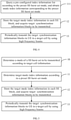
- FIG. 5 is a flowchart illustrating another method of transmitting synchronization information blocks according to an example. On the basis of the example as shown in FIG.2 , before step 11, the method further includes:
- step 10 a mode of the SS burst set to be transmitted is determined according to target cell information.
- a base station may cover several cells, for example 3 cells.
- the distribution of UE in each cell may be identical or different. If the UE in each cell are distributed similarly or identically, the base station may use the SS burst set in the same mode for transmitting synchronization information blocks to every cell.
- the base station may first select a mode of SS burst set appropriate for the target cell according to target cell information.
- FIG. 6 is a flowchart illustrating another method of transmitting synchronization information blocks according to an example. As shown in FIG. 6 , the step 10 includes:
- target cell information is acquired, where the target cell information includes at least one of the following: an identifier of the cell, a UE type in the cell, and service busyness of the cell; and
- a mode of the SS burst set suitable for the target cell is determined according to the target cell information.
- the cell information of a target cell includes at least one of the following: an identifier of the cell, a UE type in the cell, and service busyness of the cell.
- the implementations of the step 102 may include, but are not limited to, the following situations.
- the mode of SS burst set is determined according to the identifier of the target cell. It is assumed that the target cell information consists of the cell identifier only.
- the base station may predetermine a list of synchronization modes according to the type of each cell. It is assumed that cells fall into two types: a cell for dedicated devices and a normal cell. During initialization, the base station designates modes of SS burst set for each cell identifier according to the cell types. Again, it is assumed that the base station covers 3 cells. The 3 cells are referred to as cell A, cell B, and cell C.
- the cells A and B are normal cells, that is, communication with UE of various frequency bands is to be satisfied; and if the cell C is a cell for dedicated devices, for example for specific requirements such as security requirements, the cell only allows communication with UE of a certain frequency band, for example 6G, and denies access from UE of other working frequency bands.
- the preset synchronization mode list is as shown in Table 2: Table 2 Cell identifier A B C SS burst set mode Mode 5 Mode 5 Mode 1, 2, 3, or 6
- the base station may use the SS burst set as represented by Mode 5 of FIG. 3 to send SS blocks to the UE in cell A.
- the mode of SS burst set is determined according to the UE type in the target cell.
- the target cell information includes at least the type of UE which the cell allows access from.
- the base station After determining the target cell identifier, the base station queries cell's history information record and finds that, within a certain period of time, for example the first quarter of the year, UE with only two frequency bands is accessed to the cell. On the basis of the above information, the base station may adopt the SS burst set as represented by Mode 4 of FIG. 3 to broadcast SS blocks to the UE in the target cell in the first quarter of the year.
- the mode of SS burst set is determined according to the service busyness of the target cell.
- the base station queries cell's history information record to determine service busyness of the target cell in each time period, and then adopts different modes of SS burst set.
- the target cell C may transmit SS blocks using Mode 1, 2, 3 or 6. It is assumed that, according to historical statistics, the service busyness of the cell C is highest during 8:00 to 12:00, moderate during 12:00 to 22:00, and lowest during 22:00 ⁇ 8:00.
- the base station can transmit SS blocks in different SS burst set modes in different time periods, as shown in Table 3: Table 3 Time period Service busyness Mode 8:00-12:00 High Mode 1 12:00-22:00 Moderate Mode 2 or 3 22:00-8:00 Low Mode 6
- the base station uses an appropriate mode of SS burst set to transmit the SS blocks according to the service busyness of the cell. In this way, the radio resources occupied by synchronization information blocks are effectively saved, the radio resources are more efficiently utilized, and the power consumption of the base station is reduced.
- the present disclosure also provides a method of acquiring synchronization information blocks, which is applied to UE.
- FIG. 7 is a flowchart illustrating a method of acquiring synchronization information blocks according to an example. As shown in FIG. 7 , the method includes the following steps.
- step 21 a synchronization information block carried by a high frequency beam is detected according to a preset initial detection window.
- the UE After entering the target cell, the UE enables a preset initial detection window with a duration of, for example, 5 ms, to perform a blind detection for the synchronization information blocks, so that the first synchronization information block is quickly detected.
- the width of the initial detection window is generally determined according to a number of bursts with different frequency bands included in one SS burst set, that is, the SS burst set as represented by the Mode 5 in FIG. 3 is used to determine the initial detection window.
- the duration T0 of a SS burst set is 20 ms.
- the SS burst set as represented by Mode 5 includes four bursts. Therefore, the width of the initial detection window can be determined as 5 ms.
- the window can be slightly larger than 5 ms and can be represented by 5 ms+.
- step 22 mode index information of the SS burst set is acquired from the detected synchronization information block.
- the mode index information is carried in every SS block in an SS burst set of a mode transmitted by the base station.
- the UE may analyze the mode index information of the SS burst set from a preset location of the synchronization information block, for example the PBCH or other channels, or a specified field of the above preset channel.
- At least two manners may be adopted for acquiring the mode index information of the SS burst set from the synchronization information block.
- the UE After detecting the first synchronization information block, the UE acquires the mode index information of the SS burst set from the first SS block according to a preset mode index information storage protocol.
- FIG. 8 is a flowchart illustrating another method of acquiring synchronization information blocks according to an example. As shown in FIG. 8 , the foregoing step 22 includes the following steps.
- step 221 a piece of mode index information is analyzed from each of a preset quantity of the detected synchronization information blocks.
- the UE may continuously acquire a preset number, for example 4, of synchronization information blocks, and acquire a piece of mode index information of the SS burst set from each synchronization information block.
- step 222 identical pieces of mode index information among the preset quantity of the mode index information are determined as valid mode index information.
- a total of four pieces of mode index information are acquired through the step 221.
- the four pieces of the mode index information are identical, but errors may occur during decoding by the UE, for example the mode index information 2/4 is analyzed into 4/4. Consequently, an inaccurate prediction of arrival times of subsequent synchronization information blocks may arise from the analyzing error.
- identical pieces of mode index information among the preset quantity of mode index information after analyzing are determined as valid mode index information. In this way, the accuracy of mode index information is improved.
- step 23 expected arrival times of subsequent synchronization information blocks are determined according to the mode index information.
- the mode index information may be determined by the UE either in the first manner or in the second manner.
- FIG. 9 is a flowchart illustrating another method of acquiring synchronization information blocks according to an example. As shown in FIG. 9 , the foregoing step 23 includes the following steps.
- step 231 a time interval between two adjacent synchronization information blocks is determined according to the mode index information.
- the UE may calculate the time interval between two adjacent SS blocks, that is, the time interval between two adjacent and identical SS bursts.
- the time interval between two adjacent and identical SS bursts is determined as 20 ms.
- the mode index information is 4/4, which corresponds to the SS burst set as represented by Mode 1 in FIG. 3
- the time interval between two adjacent and identical SS bursts is 5 ms.
- T2 the time interval between two adjacent and identical SS bursts
- the correspondence among the mode index information, SS burst set mode, and T2 can be listed, for example, as the following Table 4: Table 4 Mode Mode 1 Mode 2 Mode 3 Mode 4 Mode 5 Mode 6 Mode index information 4/4 2/4 2/4 2/2 1/1 1/4 T2 5 ms 10 ms 10 ms 10 ms 20 ms 20 ms
- step 232 expected arrival times of subsequent synchronization information blocks are determined according to reception time of a current synchronization information block and the time interval of two adjacent synchronization information blocks.
- UE 1 detects a first synchronization information block, for example block 2 as shown in FIG. 1-2 , and the analyzed mode index information 2/4 therefrom. It is known by querying the Table 4 that, in this mode, the time interval between the arrivals of two adjacent blocks 2 at UE 1 is 10 ms. In other words, UE 1 may detect the second synchronization information block, i.e., block 2, through the detection window at time t1 + 10 ms. Accordingly, the times when subsequent block 2s arrive at UE 1 are calculated.
- step 24 during subsequent signal synchronization processes, target synchronization information blocks are acquired according to the expected arrival times.
- the UE does not enable the detection window every time when a synchronization information block arrives. Instead, the UE performs signal synchronization with a preset strategy of, for example, one detection after every two synchronization information blocks.
- the UE may calculate opening times of the detection window according to the above information. Still taking the above-mentioned UE 1 as an example. It is assumed that the UE 1 adopts a strategy of one detection after every two synchronization information blocks. After detecting the first synchronization information block at time tl, the UE 1 can enable a synchronization signal detection window of a preset width which centering on the time tl + 30 ms to detect next target synchronization information block. Similarly, the opening times of the detection window are determined according to the estimated arrival times of the target synchronization information blocks, in order to sequentially detect the target synchronization information blocks.
- the UE By using the method of acquiring synchronization information blocks provided in the examples of the present disclosure, the UE first acquires the mode index information from the detected synchronization information block, so that the UE determines the mode of SS burst set adopted by the base station for broadcasting synchronization information in the cell. Then, the time interval between every two adjacent synchronization information blocks is calculated, and the reception times of subsequent synchronization information blocks are estimated. In this way, the use of blind detection for the synchronization signal detection is avoided, radio resources of the UE are effectively saved, and the power consumption of the UE is reduced.
- the present disclosure also provides apparatus examples implemented by applying functions and examples of corresponding terminals.
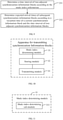
- FIG. 10 is a block diagram illustrating an apparatus for transmitting synchronization information blocks according to an example. Applied to a base station, the apparatus may include:
- FIG. 11 is a block diagram illustrating another apparatus for transmitting synchronization information blocks according to an example.
- the mode index determining module 31 may comprise: a mode index determining sub-module 311, configured to query a pre-configured index information list according to the preset SS burst set mode to acquire mode index information corresponding to the preset SS burst set mode.
- FIG. 12 is a block diagram illustrating another apparatus for transmitting synchronization information blocks according to an example.
- the storing module 32 may comprise one of the following sub-modules:
- FIG. 13 is a block diagram illustrating another apparatus for transmitting synchronization information blocks according to an example. Based on the example as shown in FIG. 10 , the apparatus may further include: a mode determining module 30, configured to determine a mode of a SS burst set to be transmitted according to target cell information.
- a mode determining module 30 configured to determine a mode of a SS burst set to be transmitted according to target cell information.
- FIG. 14 is a block diagram illustrating another apparatus for transmitting synchronization information blocks according to an example. Based on the example as shown in FIG. 13 , the mode determining module 30 may include:
- the present disclosure also provides an apparatus for acquiring synchronization information blocks applied to UE.
- FIG. 15 is a block diagram illustrating an apparatus for acquiring synchronization information blocks according to an example.
- the apparatus may include:
- FIG. 16 is a block diagram illustrating another apparatus for acquiring synchronization information blocks according to an example.
- the index information acquiring module 42 may include: a first acquiring sub-module 421, configured to acquire, after detecting a first synchronization information block, the mode index information of the SS burst set from the synchronization information block.
- FIG. 17 is a block diagram illustrating another apparatus for acquiring synchronization information blocks according to an example. Based on the example as shown in FIG. 15 , the index information acquiring module 42 may include:
- FIG. 18 is a block diagram illustrating another apparatus for acquiring synchronization information blocks according to an example.
- the time predicting module 43 may include:
- the present disclosure provides an apparatus for transmitting synchronization information blocks, including: a processor; a memory for storing processor executable instructions; where the processor is configured to:
- the present disclosure provides an apparatus for acquiring synchronization information blocks, including: a processor; a memory for storing processor executable instructions; where the processor is configured to:
- FIG. 19 is a schematic diagram illustrating a structure of an apparatus 1900 for transmitting synchronization information blocks according to an example.
- the apparatus 1900 can be provided as a base station.
- the apparatus 1900 includes a processing component 1922, a wireless transmitting/receiving component 1924, an antenna component 1926 and a signal processing component specific to a wireless interface.
- the processing component 1922 may further include one or more processors.
- One of the processors of the processing component 1922 is configured to:
- FIG. 20 is a schematic diagram illustrating a structure of an apparatus 2000 for acquiring synchronization information blocks according to an example.
- the apparatus 2000 may be UE, and may be specified as, for example, a mobile phone, a computer, a digital broadcasting terminal, a message receiving and transmitting device, a game console, a tablet device, a medical device, a fitness device, a personal digital assistant, a wearable device such as a smart watch, smart glasses, a smart bracelet, smart running shoes, etc.
- the apparatus 2000 may include one or more of the following components: a processing component 2002, a memory 2004, a power supply component 2006, a multimedia component 2008, an audio component 2010, an input/output (I/O) interface 2012, a sensor component 2014 and a communication component 2016.
- a processing component 2002 a memory 2004, a power supply component 2006, a multimedia component 2008, an audio component 2010, an input/output (I/O) interface 2012, a sensor component 2014 and a communication component 2016.
- the processing component 2002 generally controls overall operations of the apparatus 2000, such as operations associated with display, phone calls, data communications, camera operations, and recording operations.
- the processing component 2002 may include one or more processors 2020 to execute instructions to complete all or part of the steps of the above methods.
- the processing component 2002 may include one or more modules which facilitate the interaction between the processing component 2002 and other components.
- the processing component 2002 may include a multimedia module to facilitate the interaction between the multimedia component 2008 and the processing component 2002.
- the memory 2004 is to store various types of data to support the operation of the apparatus 2000. Examples of such data include instructions for any application or method operated on the apparatus 2000, contact data, phonebook data, messages, pictures, videos, and so on.
- the memory 2004 may be implemented by any type of volatile or non-volatile storage devices or a combination thereof, such as a Static Random Access Memory (SRAM), an Electrically Erasable Programmable Read-Only Memory (EEPROM), an Erasable Programmable Read-Only Memory (EPROM), a Programmable Read-Only Memory (PROM), a Read-Only Memory (ROM), a magnetic memory, a flash memory, a magnetic or optical disk.
- SRAM Static Random Access Memory
- EEPROM Electrically Erasable Programmable Read-Only Memory
- EPROM Erasable Programmable Read-Only Memory
- PROM Programmable Read-Only Memory
- ROM Read-Only Memory
- the power supply component 2006 provides power to different components of the apparatus 2000.
- the power supply component 2006 may include a power management system, one or more power supplies, and other components associated with generating, managing, and distributing power for the apparatus 2000.
- the multimedia component 2008 includes a screen providing an output interface between the apparatus 2000 and a user.
- the screen may include a Liquid Crystal Display (LCD) and a Touch Panel (TP). If the screen includes the TP, the screen may be implemented as a touch screen to receive input signals from the user.
- the TP may include one or more touch sensors to sense touches, swipes, and gestures on the TP. The touch sensors may not only sense a boundary of a touch or swipe, but also sense a duration and a pressure associated with the touch or swipe.
- the multimedia component 2008 may include a front camera and/or a rear camera. The front camera and/or rear camera may receive external multimedia data when the apparatus 2000 is in an operating mode, such as a photographing mode or a video mode. Each of the front camera and the rear camera may be a fixed optical lens system or have focal length and optical zooming capability.
- the audio component 2010 is to output and/or input an audio signal.
- the audio component 2010 includes a microphone (MIC).
- the MIC When the apparatus 2000 is in an operating mode, such as a call mode, a recording mode, and a voice recognition mode, the MIC is to receive an external audio signal.
- the received audio signal may be further stored in the memory 2004 or sent via the communication component 2016.
- the audio component 2010 further includes a speaker to output an audio signal.
- the I/O interface 2012 may provide an interface between the processing component 2002 and peripheral interface modules.
- peripheral interface modules may include a keyboard, a click wheel, buttons and so on. These buttons may include, but are not limited to, a home button, a volume button, a starting button and a locking button.
- the sensor component 2014 includes one or more sensors to provide status assessments of various aspects for the apparatus 2000.
- the sensor component 2014 may detect the on/off status of the apparatus 2000, and relative positioning of component, for example, the component is a display and a keypad of the apparatus 2000.
- the sensor component 2014 may also detect a change in position of the apparatus 2000 or a component of the apparatus 2000, a presence or absence of the contact between a user and the apparatus 2000, an orientation or an acceleration/deceleration of the apparatus 2000, and a change in temperature of the apparatus 2000.
- the sensor component 2014 may include a proximity sensor to detect the presence of a nearby object without any physical contact.
- the sensor component 2014 may further include an optical sensor, such as a Complementary Metal-Oxide-Semiconductor (CMOS) or Charged Coupled Device (CCD) image sensor which is used in imaging applications.
- CMOS Complementary Metal-Oxide-Semiconductor
- CCD Charged Coupled Device
- the sensor component 2014 may further include an acceleration sensor, a gyroscope sensor, a magnetic sensor, a pressure sensor, or a temperature sensor.
- the communication component 2016 is to facilitate wired or wireless communication between the apparatus 2000 and other devices.
- the apparatus 2000 may access a wireless network that is based on a communication standard, such as Wi-Fi, 2G or 3G, or a combination thereof.
- the communication component 2016 receives a broadcast signal or broadcast-associated information from an external broadcast management system via a broadcast channel.
- the communication component 2016 further includes a Near Field Communication (NFC) module to facilitate short-range communications.
- the NFC module may be implemented based on a Radio Frequency Identification (RFID) technology, an Infrared Data Association (IrDA) technology, an Ultra Wideband (UWB) technology, a Bluetooth ® (BT) technology and other technologies.
- RFID Radio Frequency Identification
- IrDA Infrared Data Association
- UWB Ultra Wideband
- BT Bluetooth ®
- the apparatus 2000 may be implemented by one or more Application Specific Integrated Circuits (ASICs), Digital Signal Processors (DSPs), Digital Signal Processing Devices (DSPDs), programmable Logic Devices (PLDs), Field Programmable Gate Arrays (FPGAs), controllers, microcontrollers, microprocessors, or other electronic components for performing the above methods.
- ASICs Application Specific Integrated Circuits
- DSPs Digital Signal Processors
- DSPDs Digital Signal Processing Devices
- PLDs programmable Logic Devices
- FPGAs Field Programmable Gate Arrays
- controllers microcontrollers, microprocessors, or other electronic components for performing the above methods.
- a non-transitory computer-readable storage medium including instructions, such as a memory 2004 including instructions executable by the processor 2020 of the apparatus 2000 to perform the acquisition of synchronization information blocks.
- the non-volatile computer-readable storage medium is a ROM, a random access memory (RAM), a CD-ROM, a magnetic tape, a floppy disk, or an optical data storage device.
Claims (15)
- Procédé de transmission de blocs d'informations de synchronisation, appliqué à une station de base dans un système de communication par réseau 5G, le procédé comprenant les étapes suivantes :la détermination (11) des informations d'indice de mode cible selon un mode d'ensemble de rafales de bloc d'informations de synchronisation, ensemble de rafales SS, prédéfini, les informations d'indice de mode cible indiquant le mode d'ensemble de rafales SS prédéfini, et les informations d'indice de mode cible comprenant des informations sur un nombre de fois où des rafales de signal de synchronisation, des rafales SS, avec une même bande sont transmises pendant une durée d'un ensemble de rafales SS et un nombre de fois où des rafales SS avec la même bande sont comprises pendant une durée de l'ensemble de rafales SS ;le stockage (12) des informations d'indice de mode cible dans chaque bloc d'informations de synchronisation, bloc SS, pour acquérir des blocs d'informations de synchronisation cibles à transmettre, le bloc SS comprenant un signal de synchronisation primaire et un signal de synchronisation secondaire, et le bloc SS étant chargé dans un faisceau haute fréquence ; etla transmission périodique (13) des blocs d'informations de synchronisation cibles à l'équipement utilisateur dans une cellule cible à l'aide des faisceaux haute fréquence ;chacun des ensembles de rafales SS comprenant un premier nombre prédéfini de rafales SS qui sont transmises périodiquement, chacune des rafales SS comportant un second nombre prédéfini des blocs d'informations de synchronisation cibles qui sont transmis dans une séquence spatiale, et les ensembles de rafales SS étant transmis périodiquement.
- Procédé selon la revendication 1, l'étape de détermination des informations d'indice de mode cible selon le mode d'ensemble de rafales SS prédéfini comprenant une étape :
d'interrogation (111) d'une liste d'informations d'indice préconfigurée selon le mode d'ensemble de rafales SS prédéfini pour acquérir des informations d'indice de mode correspondant au mode d'ensemble de rafales SS prédéfini. - Procédé selon la revendication 1, l'étape de stockage des informations d'indice de mode cible dans chaque bloc d'informations de synchronisation, bloc SS, pour acquérir les blocs d'informations de synchronisation cibles comprenant une étape :de stockage des informations d'indice de mode cible dans un canal de diffusion physique, PBCH, de chaque bloc d'informations de synchronisation dans l'ensemble de rafales SS du mode prédéfini ; oude stockage des informations d'indice de mode cible dans d'autres canaux de chaque bloc d'informations de synchronisation dans l'ensemble de rafales SS du mode prédéfini ; oude stockage des informations d'indice de mode cible dans une position désignée du PBCH de chaque bloc d'informations de synchronisation dans l'ensemble de rafales SS du mode prédéfini.
- Procédé d'acquisition de blocs d'informations de synchronisation, appliqué à un équipement utilisateur dans un système de communication par réseau 5G, le procédé comprenant les étapes suivantes :la détection (21) d'un bloc d'informations de synchronisation porté par un faisceau haute fréquence selon une fenêtre de détection initiale prédéfinie, le bloc d'informations de synchronisation comprenant un signal de synchronisation primaire et un signal de synchronisation secondaire ;l'acquisition (22) des informations d'indice de mode d'un ensemble de rafales SS à partir du bloc d'informations de synchronisation détecté, les informations d'indice de mode indiquant un mode d'ensemble de rafales SS, et les informations d'indice de mode comprenant des informations sur le nombre de fois où les rafales SS avec une même bande sont transmises pendant une durée d'un ensemble de rafales SS et un nombre de fois où les rafales SS avec la même bande sont comprises pendant une durée de l'ensemble de rafales SS ;la détermination (23) des temps d'arrivée prévus des blocs d'informations de synchronisation ultérieurs selon les informations d'indice de mode ; etpendant les processus de synchronisation de signaux ultérieurs, l'acquisition (24) de blocs d'informations de synchronisation cibles selon les temps d'arrivée prévus.
- Procédé selon la revendication 4, l'étape d'acquisition des informations d'indice de mode de l'ensemble de rafales SS à partir du bloc d'informations de synchronisation détecté comprenant, après la détection d'un premier bloc d'informations de synchronisation, l'étape d'acquisition des informations d'indice de mode de l'ensemble de rafales SS à partir du bloc d'informations de synchronisation.
- Procédé selon la revendication 4, l'étape d'acquisition des informations d'indice de mode de l'ensemble de rafales SS à partir du bloc d'informations de synchronisation détecté comprenant les étapes suivantes :l'analyse (221) d'un élément des informations d'indice de mode à partir de chaque bloc d'informations de synchronisation d'une quantité prédéfinie des blocs d'informations de synchronisation détectés ; etla détermination (222) d'éléments identiques des informations d'indice de mode parmi la quantité prédéfinie des informations d'indice de mode en tant qu'informations d'indice de mode valides.
- Station de base dans un système de communication par réseau 5G, la station de base comprenant :un module de détermination d'indice de mode (31), configuré pour déterminer des informations d'indice de mode cible selon un mode d'ensemble de rafales SS prédéfini, les informations d'indice de mode cible indiquant le mode d'ensemble de rafales SS prédéfini, et les informations d'indice de mode cible comprenant des informations sur un nombre de fois où des rafales de signal de synchronisation, rafales SS, avec une même bande sont transmises pendant une durée d'un ensemble de rafales SS et un nombre de fois où des rafales SS avec la même bande sont comprises pendant une durée de l'ensemble de rafales SS ;un module de stockage (32), configuré pour stocker les informations d'indice de mode cible dans chaque bloc SS pour acquérir des blocs d'informations de synchronisation cibles à transmettre, le bloc SS comprenant un signal de synchronisation primaire et un signal de synchronisation secondaire, et le bloc SS étant chargé dans un faisceau haute fréquence ; etun module de transmission (33), configuré pour transmettre périodiquement les blocs d'informations de synchronisation cibles à l'équipement utilisateur dans une cellule cible à l'aide des faisceaux haute fréquence ;chacun des ensembles de rafales SS comprenant un premier nombre prédéfini de rafales SS qui sont transmises périodiquement, chacune des rafales SS comportant un second nombre prédéfini de blocs d'informations de synchronisation cibles qui sont transmis dans une séquence spatiale, et les ensembles de rafales SS étant transmis périodiquement.
- Station de base selon la revendication 7, le module de détermination d'indice de mode comprenant :
un sous-module de détermination d'indice de mode (311), configuré pour interroger une liste d'informations d'indice préconfigurée selon le mode d'ensemble de rafales SS prédéfini pour acquérir des informations d'indice de mode correspondant au mode d'ensemble de rafales SS prédéfini. - Station de base selon la revendication 7, le module de stockage comprenant l'un quelconque des sous-modules suivants :un premier sous-module de stockage (321), configuré pour stocker les informations d'indice de mode cible dans un PBCH de chaque bloc d'informations de synchronisation dans l'ensemble de rafales SS du mode prédéfini ;un deuxième sous-module de stockage (322), configuré pour stocker les informations d'indice de mode cible dans d'autres canaux de chaque bloc d'informations de synchronisation de l'ensemble de rafales SS du mode prédéfini ; etun troisième sous-module de stockage (323), configuré pour stocker les informations d'indice de mode cible dans une position désignée du PBCH de chaque bloc d'informations de synchronisation dans l'ensemble de rafales SS du mode prédéfini.
- Station de base selon la revendication 7, l'appareil comprenant en outre :
un module de détermination de mode (30), configuré pour déterminer un mode d'un ensemble de rafales SS à transmettre selon des informations de cellule cible. - Station de base selon la revendication 10, le module de détermination de mode comprenant :un sous-module d'acquisition d'informations de cellule (301), configuré pour acquérir les informations de cellule cible, les informations de cellule cible comprenant au moins l'un des éléments suivants : un identifiant de la cellule, un type d'équipement utilisateur dans la cellule, et l'occupation de service de la cellule ; etun sous-module de détermination de mode (302), configuré pour déterminer le mode de l'ensemble de rafales SS adapté à la cellule cible selon les informations de cellule cible.
- Équipement utilisateur dans un système de communication par réseau 5G, l'équipement utilisateur comprenant :un module de détection initial (41), configuré pour détecter un bloc d'informations de synchronisation porté par un faisceau haute fréquence selon une fenêtre de détection initiale prédéfinie, le bloc d'informations de synchronisation comprenant un signal de synchronisation primaire et un signal de synchronisation secondaire ;un module d'acquisition d'informations d'indice (42), configuré pour acquérir des informations d'indice de mode d'un ensemble de rafales SS à partir du bloc d'informations de synchronisation détecté, les informations d'indice de mode indiquant un mode d'ensemble de rafales SS, et les informations d'indice de mode comprenant des informations sur un nombre de fois où les rafales SS avec une même bande sont transmises pendant une durée d'un ensemble de rafales SS et un nombre de fois où les rafales SS avec la même bande sont comprises pendant une durée de l'ensemble de rafales SS ;un module de prédiction de temps (43), configuré pour déterminer des temps d'arrivée prévus des blocs d'informations de synchronisation ultérieurs selon les informations d'indice de mode ; etun module d'acquisition de signal de synchronisation (44), configuré pour acquérir, pendant des processus de synchronisation de signal ultérieurs, des blocs d'informations de synchronisation cibles selon les temps d'arrivée prévus.
- Équipement utilisateur selon la revendication 12, le module d'acquisition d'informations d'indice comprenant :
un premier sous-module d'acquisition (421), configuré pour acquérir, après détection d'un premier bloc d'informations de synchronisation, les informations d'indice de mode de l'ensemble de rafales SS à partir du bloc d'informations de synchronisation. - Équipement utilisateur selon la revendication 12, le module d'acquisition d'informations d'indice comprenant :un sous-module d'acquisition de bloc de synchronisation (412), configuré pour analyser un élément des informations d'indice de mode à partir de chaque bloc d'informations de synchronisation d'une quantité prédéfinie des blocs d'informations de synchronisation détectés ; etun second sous-module d'acquisition (422), configuré pour déterminer des éléments identiques des informations d'indice de mode parmi la quantité prédéfinie des informations d'indice de mode en tant qu'informations d'indice de mode valides.
- Équipement utilisateur selon l'une quelconque des revendications 13 ou 14, le module de prédiction de temps comprenant :un sous-module de détermination d'intervalle de temps (431), configuré pour déterminer un intervalle de temps de deux blocs d'informations de synchronisation adjacents selon les informations d'indice de mode ; etun sous-module de pré-calcul de temps (432), configuré pour déterminer les temps d'arrivée prévus des blocs d'informations de synchronisation ultérieurs selon un temp de réception du bloc d'informations de synchronisation actuel et de l'intervalle de temps des deux blocs d'informations de synchronisation adjacents.
Applications Claiming Priority (1)
| Application Number | Priority Date | Filing Date | Title |
|---|---|---|---|
| PCT/CN2017/078439 WO2018176222A1 (fr) | 2017-03-28 | 2017-03-28 | Procédé et dispositif de transmission et d'acquisition de bloc d'informations de synchronisation |
Publications (3)
| Publication Number | Publication Date |
|---|---|
| EP3605957A1 EP3605957A1 (fr) | 2020-02-05 |
| EP3605957A4 EP3605957A4 (fr) | 2020-04-08 |
| EP3605957B1 true EP3605957B1 (fr) | 2022-03-09 |
Family
ID=60076611
Family Applications (1)
| Application Number | Title | Priority Date | Filing Date |
|---|---|---|---|
| EP17903177.8A Active EP3605957B1 (fr) | 2017-03-28 | 2017-03-28 | Procédé et dispositif de transmission et d'acquisition de bloc d'informations de synchronisation |
Country Status (5)
| Country | Link |
|---|---|
| US (1) | US11109331B2 (fr) |
| EP (1) | EP3605957B1 (fr) |
| CN (1) | CN107278383B (fr) |
| ES (1) | ES2910793T3 (fr) |
| WO (1) | WO2018176222A1 (fr) |
Cited By (1)
| Publication number | Priority date | Publication date | Assignee | Title |
|---|---|---|---|---|
| US20210258898A1 (en) * | 2020-02-13 | 2021-08-19 | Qualcomm Incorporated | Beam management in a wireless communications network |
Families Citing this family (40)
| Publication number | Priority date | Publication date | Assignee | Title |
|---|---|---|---|---|
| WO2018129196A1 (fr) * | 2017-01-09 | 2018-07-12 | Intel IP Corporation | Techniques de transmission de signal de synchronisation |
| ES2929049T3 (es) * | 2017-11-01 | 2022-11-24 | Guangdong Oppo Mobile Telecommunications Corp Ltd | Método y dispositivo de transmisión de información |
| CN109787732B (zh) * | 2017-11-14 | 2020-10-20 | 电信科学技术研究院 | 一种资源配置方法及装置、计算机存储介质 |
| WO2019095109A1 (fr) * | 2017-11-14 | 2019-05-23 | 北京小米移动软件有限公司 | Procédé d'indication d'informations dans le domaine fréquentiel d'un ensemble de ressources de commande communes d'informations minimales restantes du système |
| ES2954302T3 (es) * | 2017-11-15 | 2023-11-21 | Koninklijke Philips Nv | Método de indicación de información de periodo para el conjunto de recursos de control común de la información clave restante del sistema |
| CN109451799B (zh) | 2017-11-16 | 2021-07-06 | 北京小米移动软件有限公司 | 剩余关键系统信息的公共控制资源集合的时域信息指示方法 |
| CN109803379B (zh) * | 2017-11-16 | 2021-04-27 | 中国移动通信有限公司研究院 | 随机接入信道资源的分配方法、网络侧设备及终端 |
| CN111357351A (zh) * | 2017-11-17 | 2020-06-30 | 上海诺基亚贝尔股份有限公司 | NR中的无中断SCell操作 |
| CN109803370B (zh) * | 2017-11-17 | 2023-12-08 | 华为技术有限公司 | 指示方法,网络设备及用户设备 |
| CN109246829B (zh) * | 2017-11-17 | 2020-01-03 | 华为技术有限公司 | 通信方法和通信设备 |
| CN109802757A (zh) * | 2017-11-17 | 2019-05-24 | 华为技术有限公司 | 一种控制信息的检测方法及装置 |
| WO2019095439A1 (fr) * | 2017-11-17 | 2019-05-23 | Oppo广东移动通信有限公司 | Procédé de mesure d'indication d'intensité de signal reçu et dispositif terminal |
| CN111641491B (zh) * | 2017-12-06 | 2021-12-31 | Oppo广东移动通信有限公司 | 无线通信方法和设备 |
| WO2019116477A1 (fr) * | 2017-12-13 | 2019-06-20 | 株式会社Nttドコモ | Terminal utilisateur et procédé de communication radio |
| WO2019113914A1 (fr) * | 2017-12-15 | 2019-06-20 | 南通朗恒通信技术有限公司 | Procédé et dispositif utilisés dans un nœud de communication d'une communication sans fil |
| CN110022191B (zh) * | 2018-01-08 | 2021-08-17 | 维沃移动通信有限公司 | 信息发送方法、接收方法、网络设备及终端 |
| CN108390747B (zh) * | 2018-01-19 | 2021-10-22 | 宇龙计算机通信科技(深圳)有限公司 | 一种同步信号的发送方法和装置 |
| CN110099420A (zh) * | 2018-01-31 | 2019-08-06 | 华为技术有限公司 | 一种无线通信方法及其相关设备 |
| US10912129B2 (en) | 2018-02-08 | 2021-02-02 | Qualcomm Incorporated | SSB multiplexing and RMSI monitoring in NR-U |
| EP3753301B1 (fr) | 2018-02-13 | 2023-07-12 | ZTE Corporation | Procédé et appareil d'acquisition d'informations de cellules |
| EP3759975A4 (fr) * | 2018-02-26 | 2021-11-24 | Nokia Technologies Oy | Procédés et appareils pour une détermination d'exigence d'efficacité de mesure d'équipement utilisateur |
| BR112019026144A2 (pt) * | 2018-03-20 | 2020-06-30 | Guangdong Oppo Mobile Telecommunications Corp., Ltd. | método para paginação, dispositivo de rede, e dispositivo terminal |
| WO2019179456A1 (fr) * | 2018-03-21 | 2019-09-26 | Mediatek Singapore Pte. Ltd. | Appareils et procédés de gestion d'informations de localisation d'un système 5g (5gs) |
| ES2946238T3 (es) * | 2018-04-02 | 2023-07-14 | Beijing Xiaomi Mobile Software Co Ltd | Método y aparato para transmitir información de difusión sincronizada |
| CN110351835B (zh) * | 2018-04-03 | 2021-09-07 | 维沃移动通信有限公司 | 一种频段确定方法和装置 |
| ES2962577T3 (es) | 2018-04-04 | 2024-03-19 | Huawei Tech Co Ltd | Transmisión de información del sistema |
| CN112042232B (zh) * | 2018-04-04 | 2022-06-10 | 中兴通讯股份有限公司 | 为信息请求分配随机接入信道资源 |
| CN110446271B (zh) * | 2018-05-02 | 2022-11-01 | 中国移动通信有限公司研究院 | 一种随机接入的方法、用户设备及网络侧设备 |
| CN110474750B (zh) * | 2018-05-11 | 2021-11-19 | 华为技术有限公司 | 信号传输方法、相关设备及系统 |
| CN110475236B (zh) * | 2018-05-11 | 2022-01-25 | 中兴通讯股份有限公司 | 一种时域位置信息确定方法及装置 |
| CN110474744B (zh) * | 2018-05-11 | 2021-02-26 | 维沃移动通信有限公司 | 一种传输资源指示方法、网络设备及终端 |
| CN110611948B (zh) * | 2018-06-14 | 2021-01-08 | 维沃移动通信有限公司 | 同步信号块的传输方法、网络设备及终端 |
| CN110636638B (zh) * | 2018-06-25 | 2023-04-21 | 中兴通讯股份有限公司 | 邻区管理方法、装置、基站及存储介质 |
| CN110691408B (zh) * | 2018-07-06 | 2022-06-14 | 维沃移动通信有限公司 | 信息传输方法、网络设备及终端 |
| RU2759426C1 (ru) * | 2018-08-10 | 2021-11-12 | Бейдзин Сяоми Мобайл Софтвэр Ко., Лтд. | Способ и устройство для передачи опорного сигнала, способ и устройство для приема опорного сигнала, устройство, установленное на транспортном средстве, и терминал |
| EP3860186A4 (fr) * | 2018-09-30 | 2021-10-20 | Guangdong Oppo Mobile Telecommunications Corp., Ltd. | Procédé de configuration, dispositif de communication, et support de stockage lisible par ordinateur |
| CN111050298B (zh) * | 2018-10-15 | 2021-10-22 | 华为技术有限公司 | 一种同步信号的发送方法和通信设备 |
| CN116941290A (zh) * | 2021-03-02 | 2023-10-24 | 华为技术有限公司 | 一种无线通信方法、通信装置及通信系统 |
| CN114286328A (zh) * | 2021-10-11 | 2022-04-05 | 北京物资学院 | 一种无线通信系统中的信号处理方法和装置 |
| CN117014969A (zh) * | 2022-04-29 | 2023-11-07 | 维沃移动通信有限公司 | 数据的控制方法、装置及通信设备 |
Family Cites Families (20)
| Publication number | Priority date | Publication date | Assignee | Title |
|---|---|---|---|---|
| US6556639B1 (en) | 1999-06-24 | 2003-04-29 | Ibiquity Digital Corporation | Method and apparatus for determining transmission mode and synchronization for a digital audio broadcasting signal |
| KR101231512B1 (ko) | 2008-05-09 | 2013-02-07 | 한국전자통신연구원 | 무선통신시스템의 셀 탐색에서 주파수 오프셋에 강한 심볼 동기 획득 장치 및 방법 |
| EP2159926B1 (fr) * | 2008-08-26 | 2019-10-23 | Agence Spatiale Europeenne | Procédés, appareils et système pour la communication en dispersion spectrale asynchrone |
| CN101771439B (zh) * | 2009-11-19 | 2014-05-14 | 海能达通信股份有限公司 | 一种集群通信方法及网络侧设备 |
| JP5936498B2 (ja) * | 2012-01-16 | 2016-06-22 | ルネサスエレクトロニクス株式会社 | Usb3.0デバイス及び制御方法 |
| US10362610B2 (en) * | 2016-09-19 | 2019-07-23 | Samsung Electronics Co., Ltd. | Method and apparatus for mapping initial access signals in wireless systems |
| US10389567B2 (en) * | 2016-11-03 | 2019-08-20 | Samsung Electronics Co., Ltd. | Method and apparatus for synchronization signal design |
| CN110140381A (zh) * | 2016-11-04 | 2019-08-16 | 瑞典爱立信有限公司 | 用于编码多个小区和波束的系统信息的系统和方法 |
| AU2017387480B2 (en) * | 2016-12-28 | 2022-03-24 | FG Innovation Company Limited | Base station apparatus, terminal apparatus, communication method, and integrated circuit |
| WO2018128566A1 (fr) * | 2017-01-05 | 2018-07-12 | Telefonaktiebolaget Lm Ericsson (Publ) | Procédés et dispositifs d'émission/réception d'informations relatives à la synchronisation |
| US10425264B2 (en) * | 2017-01-09 | 2019-09-24 | Lg Electronics Inc. | Method of transmitting synchronization signal and apparatus therefor |
| MX2019008596A (es) * | 2017-02-02 | 2019-10-30 | Sharp Kk | Transmision y recepcion de señales de sincronizacion para sistema de radio. |
| KR101988325B1 (ko) * | 2017-02-06 | 2019-06-12 | 엘지전자 주식회사 | 무선 통신 시스템에서 단말과 기지국간 신호 송수신 방법 및 이를 지원하는 장치 |
| ES2937390T3 (es) * | 2017-02-07 | 2023-03-28 | Innovative Tech Lab Co Ltd | Método y aparato para la configuración de canales de difusión y para la transmisión y recepción de canales de difusión para un sistema de comunicaciones |
| US10568102B2 (en) * | 2017-02-23 | 2020-02-18 | Qualcomm Incorporated | Usage of synchronization signal block index in new radio |
| US10523354B2 (en) * | 2017-02-24 | 2019-12-31 | Samsung Electronics Co., Ltd. | Method and apparatus for design of NR-SS burst set |
| WO2018174587A1 (fr) * | 2017-03-23 | 2018-09-27 | Samsung Electronics Co., Ltd. | Procédé et appareil pour la transmission de pbch dans un système basé sur des faisceaux multiples |
| CA3057584C (fr) * | 2017-03-24 | 2023-05-23 | Telefonaktiebolaget Lm Ericsson (Publ) | Transmission de canal de diffusion nr |
| EP3520490B1 (fr) * | 2017-05-05 | 2022-01-12 | ZTE Corporation | Techniques de communication d'informations de temporisation de signal de synchronisation |
| CN110365438B (zh) * | 2018-03-26 | 2021-05-11 | 华为技术有限公司 | 信号传输方法、相关设备及系统 |
-
2017
- 2017-03-28 WO PCT/CN2017/078439 patent/WO2018176222A1/fr unknown
- 2017-03-28 ES ES17903177T patent/ES2910793T3/es active Active
- 2017-03-28 EP EP17903177.8A patent/EP3605957B1/fr active Active
- 2017-03-28 CN CN201780000184.3A patent/CN107278383B/zh active Active
-
2019
- 2019-09-28 US US16/586,918 patent/US11109331B2/en active Active
Cited By (1)
| Publication number | Priority date | Publication date | Assignee | Title |
|---|---|---|---|---|
| US20210258898A1 (en) * | 2020-02-13 | 2021-08-19 | Qualcomm Incorporated | Beam management in a wireless communications network |
Also Published As
| Publication number | Publication date |
|---|---|
| EP3605957A1 (fr) | 2020-02-05 |
| CN107278383A (zh) | 2017-10-20 |
| CN107278383B (zh) | 2020-08-14 |
| US20200029289A1 (en) | 2020-01-23 |
| EP3605957A4 (fr) | 2020-04-08 |
| ES2910793T3 (es) | 2022-05-13 |
| US11109331B2 (en) | 2021-08-31 |
| WO2018176222A1 (fr) | 2018-10-04 |
Similar Documents
| Publication | Publication Date | Title |
|---|---|---|
| EP3605957B1 (fr) | Procédé et dispositif de transmission et d'acquisition de bloc d'informations de synchronisation | |
| KR102647507B1 (ko) | 세컨더리 서빙 셀의 빔 실패의 보고 방법, 장치 및 저장 매체 | |
| CN108886788B (zh) | 传输信息的方法和装置、基站及用户设备 | |
| CN110945897B (zh) | 波束失败检测资源分配方法、装置及存储介质 | |
| CN109451861B (zh) | 资源配置方法、装置、用户设备及基站 | |
| US11637594B2 (en) | Data transmission method and apparatus via a plurality of beams | |
| US11490263B2 (en) | Assisted discovery of a local private 3GPP network via a local private non-3GPP wireless network | |
| US10999002B2 (en) | Method and apparatus for determining modulation and coding scheme | |
| CN113517963B (zh) | 上行信号或信道处理方法、装置及可读存储介质 | |
| US20230308988A1 (en) | Method, network device and terminal device for remaining minimum system information | |
| US20230283352A1 (en) | Beam determining method and apparatus, and storage medium | |
| CN110383705A (zh) | 一种训练传输波束的方法、装置及系统 | |
| CN113973261A (zh) | 一种定位处理方法、装置及设备 | |
| CN113973333A (zh) | 一种信道测量处理方法、装置及设备 | |
| RU2788195C1 (ru) | Способ и устройство для предоставления отчета о сбое луча вторичной обслуживающей соты, и носитель информации | |
| WO2024032439A1 (fr) | Procédé de positionnement, terminal et périphérique côté réseau | |
| WO2023070481A1 (fr) | Dispositifs, procédés et supports lisibles par ordinateur pour le positionnement dans un état inactif rrc | |
| WO2023005837A1 (fr) | Procédé et appareil de positionnement, dispositif de communication et support | |
| CN113517966B (zh) | 下行参考信号处理方法、装置及可读存储介质 | |
| RU2800678C1 (ru) | Способ и устройство для выделения ресурсов обнаружения отказа луча | |
| WO2023116905A1 (fr) | Procédé de traitement de signal de référence de positionnement, dispositif, et support de stockage lisible | |
| CN116830752A (zh) | 一种通信方法、装置以及可读存储介质 | |
| CN116208909A (zh) | 定位方法、装置、终端及通信设备 | |
| CN117136520A (zh) | 一种通信方法、通信装置及通信设备 | |
| CN116830512A (zh) | 信息指示方法、装置及存储介质 |
Legal Events
| Date | Code | Title | Description |
|---|---|---|---|
| STAA | Information on the status of an ep patent application or granted ep patent |
Free format text: STATUS: THE INTERNATIONAL PUBLICATION HAS BEEN MADE |
|
| PUAI | Public reference made under article 153(3) epc to a published international application that has entered the european phase |
Free format text: ORIGINAL CODE: 0009012 |
|
| STAA | Information on the status of an ep patent application or granted ep patent |
Free format text: STATUS: REQUEST FOR EXAMINATION WAS MADE |
|
| 17P | Request for examination filed |
Effective date: 20191024 |
|
| AK | Designated contracting states |
Kind code of ref document: A1 Designated state(s): AL AT BE BG CH CY CZ DE DK EE ES FI FR GB GR HR HU IE IS IT LI LT LU LV MC MK MT NL NO PL PT RO RS SE SI SK SM TR |
|
| AX | Request for extension of the european patent |
Extension state: BA ME |
|
| A4 | Supplementary search report drawn up and despatched |
Effective date: 20200309 |
|
| RIC1 | Information provided on ipc code assigned before grant |
Ipc: H04W 72/04 20090101ALI20200303BHEP Ipc: H04W 56/00 20090101ALI20200303BHEP Ipc: H04W 74/08 20090101ALI20200303BHEP Ipc: H04L 12/42 20060101AFI20200303BHEP Ipc: H04W 72/00 20090101ALI20200303BHEP |
|
| DAV | Request for validation of the european patent (deleted) | ||
| DAX | Request for extension of the european patent (deleted) | ||
| STAA | Information on the status of an ep patent application or granted ep patent |
Free format text: STATUS: EXAMINATION IS IN PROGRESS |
|
| 17Q | First examination report despatched |
Effective date: 20210416 |
|
| REG | Reference to a national code |
Ref country code: DE Ref legal event code: R079 Ref document number: 602017054531 Country of ref document: DE Free format text: PREVIOUS MAIN CLASS: H04L0012420000 Ipc: H04W0048120000 |
|
| GRAP | Despatch of communication of intention to grant a patent |
Free format text: ORIGINAL CODE: EPIDOSNIGR1 |
|
| STAA | Information on the status of an ep patent application or granted ep patent |
Free format text: STATUS: GRANT OF PATENT IS INTENDED |
|
| RIC1 | Information provided on ipc code assigned before grant |
Ipc: H04W 56/00 20090101ALI20210831BHEP Ipc: H04W 48/12 20090101AFI20210831BHEP |
|
| INTG | Intention to grant announced |
Effective date: 20210930 |
|
| GRAS | Grant fee paid |
Free format text: ORIGINAL CODE: EPIDOSNIGR3 |
|
| GRAA | (expected) grant |
Free format text: ORIGINAL CODE: 0009210 |
|
| STAA | Information on the status of an ep patent application or granted ep patent |
Free format text: STATUS: THE PATENT HAS BEEN GRANTED |
|
| AK | Designated contracting states |
Kind code of ref document: B1 Designated state(s): AL AT BE BG CH CY CZ DE DK EE ES FI FR GB GR HR HU IE IS IT LI LT LU LV MC MK MT NL NO PL PT RO RS SE SI SK SM TR |
|
| REG | Reference to a national code |
Ref country code: CH Ref legal event code: EP Ref country code: AT Ref legal event code: REF Ref document number: 1475155 Country of ref document: AT Kind code of ref document: T Effective date: 20220315 |
|
| REG | Reference to a national code |
Ref country code: DE Ref legal event code: R096 Ref document number: 602017054531 Country of ref document: DE |
|
| REG | Reference to a national code |
Ref country code: IE Ref legal event code: FG4D |
|
| REG | Reference to a national code |
Ref country code: NL Ref legal event code: FP |
|
| REG | Reference to a national code |
Ref country code: ES Ref legal event code: FG2A Ref document number: 2910793 Country of ref document: ES Kind code of ref document: T3 Effective date: 20220513 |
|
| REG | Reference to a national code |
Ref country code: LT Ref legal event code: MG9D |
|
| PG25 | Lapsed in a contracting state [announced via postgrant information from national office to epo] |
Ref country code: SE Free format text: LAPSE BECAUSE OF FAILURE TO SUBMIT A TRANSLATION OF THE DESCRIPTION OR TO PAY THE FEE WITHIN THE PRESCRIBED TIME-LIMIT Effective date: 20220309 Ref country code: RS Free format text: LAPSE BECAUSE OF FAILURE TO SUBMIT A TRANSLATION OF THE DESCRIPTION OR TO PAY THE FEE WITHIN THE PRESCRIBED TIME-LIMIT Effective date: 20220309 Ref country code: NO Free format text: LAPSE BECAUSE OF FAILURE TO SUBMIT A TRANSLATION OF THE DESCRIPTION OR TO PAY THE FEE WITHIN THE PRESCRIBED TIME-LIMIT Effective date: 20220609 Ref country code: LT Free format text: LAPSE BECAUSE OF FAILURE TO SUBMIT A TRANSLATION OF THE DESCRIPTION OR TO PAY THE FEE WITHIN THE PRESCRIBED TIME-LIMIT Effective date: 20220309 Ref country code: HR Free format text: LAPSE BECAUSE OF FAILURE TO SUBMIT A TRANSLATION OF THE DESCRIPTION OR TO PAY THE FEE WITHIN THE PRESCRIBED TIME-LIMIT Effective date: 20220309 Ref country code: BG Free format text: LAPSE BECAUSE OF FAILURE TO SUBMIT A TRANSLATION OF THE DESCRIPTION OR TO PAY THE FEE WITHIN THE PRESCRIBED TIME-LIMIT Effective date: 20220609 |
|
| REG | Reference to a national code |
Ref country code: AT Ref legal event code: MK05 Ref document number: 1475155 Country of ref document: AT Kind code of ref document: T Effective date: 20220309 |
|
| PG25 | Lapsed in a contracting state [announced via postgrant information from national office to epo] |
Ref country code: LV Free format text: LAPSE BECAUSE OF FAILURE TO SUBMIT A TRANSLATION OF THE DESCRIPTION OR TO PAY THE FEE WITHIN THE PRESCRIBED TIME-LIMIT Effective date: 20220309 Ref country code: GR Free format text: LAPSE BECAUSE OF FAILURE TO SUBMIT A TRANSLATION OF THE DESCRIPTION OR TO PAY THE FEE WITHIN THE PRESCRIBED TIME-LIMIT Effective date: 20220610 Ref country code: FI Free format text: LAPSE BECAUSE OF FAILURE TO SUBMIT A TRANSLATION OF THE DESCRIPTION OR TO PAY THE FEE WITHIN THE PRESCRIBED TIME-LIMIT Effective date: 20220309 |
|
| PG25 | Lapsed in a contracting state [announced via postgrant information from national office to epo] |
Ref country code: SM Free format text: LAPSE BECAUSE OF FAILURE TO SUBMIT A TRANSLATION OF THE DESCRIPTION OR TO PAY THE FEE WITHIN THE PRESCRIBED TIME-LIMIT Effective date: 20220309 Ref country code: SK Free format text: LAPSE BECAUSE OF FAILURE TO SUBMIT A TRANSLATION OF THE DESCRIPTION OR TO PAY THE FEE WITHIN THE PRESCRIBED TIME-LIMIT Effective date: 20220309 Ref country code: RO Free format text: LAPSE BECAUSE OF FAILURE TO SUBMIT A TRANSLATION OF THE DESCRIPTION OR TO PAY THE FEE WITHIN THE PRESCRIBED TIME-LIMIT Effective date: 20220309 Ref country code: PT Free format text: LAPSE BECAUSE OF FAILURE TO SUBMIT A TRANSLATION OF THE DESCRIPTION OR TO PAY THE FEE WITHIN THE PRESCRIBED TIME-LIMIT Effective date: 20220711 Ref country code: EE Free format text: LAPSE BECAUSE OF FAILURE TO SUBMIT A TRANSLATION OF THE DESCRIPTION OR TO PAY THE FEE WITHIN THE PRESCRIBED TIME-LIMIT Effective date: 20220309 Ref country code: CZ Free format text: LAPSE BECAUSE OF FAILURE TO SUBMIT A TRANSLATION OF THE DESCRIPTION OR TO PAY THE FEE WITHIN THE PRESCRIBED TIME-LIMIT Effective date: 20220309 Ref country code: AT Free format text: LAPSE BECAUSE OF FAILURE TO SUBMIT A TRANSLATION OF THE DESCRIPTION OR TO PAY THE FEE WITHIN THE PRESCRIBED TIME-LIMIT Effective date: 20220309 |
|
| REG | Reference to a national code |
Ref country code: CH Ref legal event code: PL |
|
| PG25 | Lapsed in a contracting state [announced via postgrant information from national office to epo] |
Ref country code: PL Free format text: LAPSE BECAUSE OF FAILURE TO SUBMIT A TRANSLATION OF THE DESCRIPTION OR TO PAY THE FEE WITHIN THE PRESCRIBED TIME-LIMIT Effective date: 20220309 Ref country code: IS Free format text: LAPSE BECAUSE OF FAILURE TO SUBMIT A TRANSLATION OF THE DESCRIPTION OR TO PAY THE FEE WITHIN THE PRESCRIBED TIME-LIMIT Effective date: 20220709 Ref country code: AL Free format text: LAPSE BECAUSE OF FAILURE TO SUBMIT A TRANSLATION OF THE DESCRIPTION OR TO PAY THE FEE WITHIN THE PRESCRIBED TIME-LIMIT Effective date: 20220309 |
|
| REG | Reference to a national code |
Ref country code: BE Ref legal event code: MM Effective date: 20220331 |
|
| REG | Reference to a national code |
Ref country code: DE Ref legal event code: R097 Ref document number: 602017054531 Country of ref document: DE |
|
| PLBE | No opposition filed within time limit |
Free format text: ORIGINAL CODE: 0009261 |
|
| STAA | Information on the status of an ep patent application or granted ep patent |
Free format text: STATUS: NO OPPOSITION FILED WITHIN TIME LIMIT |
|
| PG25 | Lapsed in a contracting state [announced via postgrant information from national office to epo] |
Ref country code: MC Free format text: LAPSE BECAUSE OF FAILURE TO SUBMIT A TRANSLATION OF THE DESCRIPTION OR TO PAY THE FEE WITHIN THE PRESCRIBED TIME-LIMIT Effective date: 20220309 Ref country code: LU Free format text: LAPSE BECAUSE OF NON-PAYMENT OF DUE FEES Effective date: 20220328 Ref country code: LI Free format text: LAPSE BECAUSE OF NON-PAYMENT OF DUE FEES Effective date: 20220331 Ref country code: IE Free format text: LAPSE BECAUSE OF NON-PAYMENT OF DUE FEES Effective date: 20220328 Ref country code: DK Free format text: LAPSE BECAUSE OF FAILURE TO SUBMIT A TRANSLATION OF THE DESCRIPTION OR TO PAY THE FEE WITHIN THE PRESCRIBED TIME-LIMIT Effective date: 20220309 Ref country code: CH Free format text: LAPSE BECAUSE OF NON-PAYMENT OF DUE FEES Effective date: 20220331 |
|
| 26N | No opposition filed |
Effective date: 20221212 |
|
| PG25 | Lapsed in a contracting state [announced via postgrant information from national office to epo] |
Ref country code: SI Free format text: LAPSE BECAUSE OF FAILURE TO SUBMIT A TRANSLATION OF THE DESCRIPTION OR TO PAY THE FEE WITHIN THE PRESCRIBED TIME-LIMIT Effective date: 20220309 Ref country code: BE Free format text: LAPSE BECAUSE OF NON-PAYMENT OF DUE FEES Effective date: 20220331 |
|
| PGFP | Annual fee paid to national office [announced via postgrant information from national office to epo] |
Ref country code: FR Payment date: 20230327 Year of fee payment: 7 |
|
| PGFP | Annual fee paid to national office [announced via postgrant information from national office to epo] |
Ref country code: GB Payment date: 20230322 Year of fee payment: 7 Ref country code: DE Payment date: 20220620 Year of fee payment: 7 |
|
| P01 | Opt-out of the competence of the unified patent court (upc) registered |
Effective date: 20230523 |
|
| PGFP | Annual fee paid to national office [announced via postgrant information from national office to epo] |
Ref country code: NL Payment date: 20230321 Year of fee payment: 7 |
|
| PG25 | Lapsed in a contracting state [announced via postgrant information from national office to epo] |
Ref country code: IT Free format text: LAPSE BECAUSE OF FAILURE TO SUBMIT A TRANSLATION OF THE DESCRIPTION OR TO PAY THE FEE WITHIN THE PRESCRIBED TIME-LIMIT Effective date: 20220309 |
|
| PGFP | Annual fee paid to national office [announced via postgrant information from national office to epo] |
Ref country code: ES Payment date: 20230529 Year of fee payment: 7 |