EP3605778A1 - Unité et système d'équilibrage sans fil pour cellule de batterie - Google Patents
Unité et système d'équilibrage sans fil pour cellule de batterie Download PDFInfo
- Publication number
- EP3605778A1 EP3605778A1 EP18186368.9A EP18186368A EP3605778A1 EP 3605778 A1 EP3605778 A1 EP 3605778A1 EP 18186368 A EP18186368 A EP 18186368A EP 3605778 A1 EP3605778 A1 EP 3605778A1
- Authority
- EP
- European Patent Office
- Prior art keywords
- cell
- balancing
- balancing unit
- state parameters
- units
- Prior art date
- Legal status (The legal status is an assumption and is not a legal conclusion. Google has not performed a legal analysis and makes no representation as to the accuracy of the status listed.)
- Granted
Links
Images

Classifications
-
- H—ELECTRICITY
- H02—GENERATION; CONVERSION OR DISTRIBUTION OF ELECTRIC POWER
- H02J—ELECTRIC POWER NETWORKS; CIRCUIT ARRANGEMENTS OR SYSTEMS FOR SUPPLYING OR DISTRIBUTING ELECTRIC POWER; SYSTEMS FOR STORING ELECTRIC ENERGY
- H02J7/00—Circuit arrangements for charging or discharging batteries or for supplying loads from batteries
- H02J7/50—Circuit arrangements for charging or discharging batteries or for supplying loads from batteries acting upon multiple batteries simultaneously or sequentially
- H02J7/52—Circuit arrangements for charging or discharging batteries or for supplying loads from batteries acting upon multiple batteries simultaneously or sequentially for charge balancing, e.g. equalisation of charge between batteries
- H02J7/54—Passive balancing, e.g. using resistors or parallel MOSFETs
-
- B—PERFORMING OPERATIONS; TRANSPORTING
- B60—VEHICLES IN GENERAL
- B60L—PROPULSION OF ELECTRICALLY-PROPELLED VEHICLES; SUPPLYING ELECTRIC POWER FOR AUXILIARY EQUIPMENT OF ELECTRICALLY-PROPELLED VEHICLES; ELECTRODYNAMIC BRAKE SYSTEMS FOR VEHICLES IN GENERAL; MAGNETIC SUSPENSION OR LEVITATION FOR VEHICLES; MONITORING OPERATING VARIABLES OF ELECTRICALLY-PROPELLED VEHICLES; ELECTRIC SAFETY DEVICES FOR ELECTRICALLY-PROPELLED VEHICLES
- B60L58/00—Methods or circuit arrangements for monitoring or controlling batteries or fuel cells, specially adapted for electric vehicles
- B60L58/10—Methods or circuit arrangements for monitoring or controlling batteries or fuel cells, specially adapted for electric vehicles for monitoring or controlling batteries
- B60L58/18—Methods or circuit arrangements for monitoring or controlling batteries or fuel cells, specially adapted for electric vehicles for monitoring or controlling batteries of two or more battery modules
- B60L58/22—Balancing the charge of battery modules
-
- H—ELECTRICITY
- H01—ELECTRIC ELEMENTS
- H01M—PROCESSES OR MEANS, e.g. BATTERIES, FOR THE DIRECT CONVERSION OF CHEMICAL ENERGY INTO ELECTRICAL ENERGY
- H01M10/00—Secondary cells; Manufacture thereof
- H01M10/42—Methods or arrangements for servicing or maintenance of secondary cells or secondary half-cells
- H01M10/4207—Methods or arrangements for servicing or maintenance of secondary cells or secondary half-cells for several batteries or cells simultaneously or sequentially
-
- H—ELECTRICITY
- H01—ELECTRIC ELEMENTS
- H01M—PROCESSES OR MEANS, e.g. BATTERIES, FOR THE DIRECT CONVERSION OF CHEMICAL ENERGY INTO ELECTRICAL ENERGY
- H01M10/00—Secondary cells; Manufacture thereof
- H01M10/42—Methods or arrangements for servicing or maintenance of secondary cells or secondary half-cells
- H01M10/425—Structural combination with electronic components, e.g. electronic circuits integrated to the outside of the casing
-
- H—ELECTRICITY
- H01—ELECTRIC ELEMENTS
- H01M—PROCESSES OR MEANS, e.g. BATTERIES, FOR THE DIRECT CONVERSION OF CHEMICAL ENERGY INTO ELECTRICAL ENERGY
- H01M10/00—Secondary cells; Manufacture thereof
- H01M10/42—Methods or arrangements for servicing or maintenance of secondary cells or secondary half-cells
- H01M10/48—Accumulators combined with arrangements for measuring, testing or indicating the condition of cells, e.g. the level or density of the electrolyte
- H01M10/482—Accumulators combined with arrangements for measuring, testing or indicating the condition of cells, e.g. the level or density of the electrolyte for several batteries or cells simultaneously or sequentially
-
- H—ELECTRICITY
- H02—GENERATION; CONVERSION OR DISTRIBUTION OF ELECTRIC POWER
- H02J—ELECTRIC POWER NETWORKS; CIRCUIT ARRANGEMENTS OR SYSTEMS FOR SUPPLYING OR DISTRIBUTING ELECTRIC POWER; SYSTEMS FOR STORING ELECTRIC ENERGY
- H02J50/00—Circuit arrangements or systems for wireless supply or distribution of electric power
- H02J50/10—Circuit arrangements or systems for wireless supply or distribution of electric power using inductive coupling
-
- H—ELECTRICITY
- H02—GENERATION; CONVERSION OR DISTRIBUTION OF ELECTRIC POWER
- H02J—ELECTRIC POWER NETWORKS; CIRCUIT ARRANGEMENTS OR SYSTEMS FOR SUPPLYING OR DISTRIBUTING ELECTRIC POWER; SYSTEMS FOR STORING ELECTRIC ENERGY
- H02J50/00—Circuit arrangements or systems for wireless supply or distribution of electric power
- H02J50/80—Circuit arrangements or systems for wireless supply or distribution of electric power involving the exchange of data, concerning supply or distribution of electric power, between transmitting devices and receiving devices
-
- H—ELECTRICITY
- H02—GENERATION; CONVERSION OR DISTRIBUTION OF ELECTRIC POWER
- H02J—ELECTRIC POWER NETWORKS; CIRCUIT ARRANGEMENTS OR SYSTEMS FOR SUPPLYING OR DISTRIBUTING ELECTRIC POWER; SYSTEMS FOR STORING ELECTRIC ENERGY
- H02J7/00—Circuit arrangements for charging or discharging batteries or for supplying loads from batteries
- H02J7/50—Circuit arrangements for charging or discharging batteries or for supplying loads from batteries acting upon multiple batteries simultaneously or sequentially
- H02J7/52—Circuit arrangements for charging or discharging batteries or for supplying loads from batteries acting upon multiple batteries simultaneously or sequentially for charge balancing, e.g. equalisation of charge between batteries
-
- H—ELECTRICITY
- H02—GENERATION; CONVERSION OR DISTRIBUTION OF ELECTRIC POWER
- H02J—ELECTRIC POWER NETWORKS; CIRCUIT ARRANGEMENTS OR SYSTEMS FOR SUPPLYING OR DISTRIBUTING ELECTRIC POWER; SYSTEMS FOR STORING ELECTRIC ENERGY
- H02J7/00—Circuit arrangements for charging or discharging batteries or for supplying loads from batteries
- H02J7/50—Circuit arrangements for charging or discharging batteries or for supplying loads from batteries acting upon multiple batteries simultaneously or sequentially
- H02J7/52—Circuit arrangements for charging or discharging batteries or for supplying loads from batteries acting upon multiple batteries simultaneously or sequentially for charge balancing, e.g. equalisation of charge between batteries
- H02J7/56—Active balancing, e.g. using capacitor-based, inductor-based or DC-DC converters
-
- H—ELECTRICITY
- H02—GENERATION; CONVERSION OR DISTRIBUTION OF ELECTRIC POWER
- H02J—ELECTRIC POWER NETWORKS; CIRCUIT ARRANGEMENTS OR SYSTEMS FOR SUPPLYING OR DISTRIBUTING ELECTRIC POWER; SYSTEMS FOR STORING ELECTRIC ENERGY
- H02J7/00—Circuit arrangements for charging or discharging batteries or for supplying loads from batteries
- H02J7/80—Circuit arrangements for charging or discharging batteries or for supplying loads from batteries including monitoring or indicating arrangements
- H02J7/82—Control of state of charge [SOC]
- H02J7/825—Detection of fully charged condition
-
- H—ELECTRICITY
- H01—ELECTRIC ELEMENTS
- H01M—PROCESSES OR MEANS, e.g. BATTERIES, FOR THE DIRECT CONVERSION OF CHEMICAL ENERGY INTO ELECTRICAL ENERGY
- H01M10/00—Secondary cells; Manufacture thereof
- H01M10/42—Methods or arrangements for servicing or maintenance of secondary cells or secondary half-cells
- H01M10/425—Structural combination with electronic components, e.g. electronic circuits integrated to the outside of the casing
- H01M2010/4271—Battery management systems including electronic circuits, e.g. control of current or voltage to keep battery in healthy state, cell balancing
-
- H—ELECTRICITY
- H01—ELECTRIC ELEMENTS
- H01M—PROCESSES OR MEANS, e.g. BATTERIES, FOR THE DIRECT CONVERSION OF CHEMICAL ENERGY INTO ELECTRICAL ENERGY
- H01M10/00—Secondary cells; Manufacture thereof
- H01M10/42—Methods or arrangements for servicing or maintenance of secondary cells or secondary half-cells
- H01M10/425—Structural combination with electronic components, e.g. electronic circuits integrated to the outside of the casing
- H01M2010/4278—Systems for data transfer from batteries, e.g. transfer of battery parameters to a controller, data transferred between battery controller and main controller
-
- Y—GENERAL TAGGING OF NEW TECHNOLOGICAL DEVELOPMENTS; GENERAL TAGGING OF CROSS-SECTIONAL TECHNOLOGIES SPANNING OVER SEVERAL SECTIONS OF THE IPC; TECHNICAL SUBJECTS COVERED BY FORMER USPC CROSS-REFERENCE ART COLLECTIONS [XRACs] AND DIGESTS
- Y02—TECHNOLOGIES OR APPLICATIONS FOR MITIGATION OR ADAPTATION AGAINST CLIMATE CHANGE
- Y02E—REDUCTION OF GREENHOUSE GAS [GHG] EMISSIONS, RELATED TO ENERGY GENERATION, TRANSMISSION OR DISTRIBUTION
- Y02E60/00—Enabling technologies; Technologies with a potential or indirect contribution to GHG emissions mitigation
- Y02E60/10—Energy storage using batteries
-
- Y—GENERAL TAGGING OF NEW TECHNOLOGICAL DEVELOPMENTS; GENERAL TAGGING OF CROSS-SECTIONAL TECHNOLOGIES SPANNING OVER SEVERAL SECTIONS OF THE IPC; TECHNICAL SUBJECTS COVERED BY FORMER USPC CROSS-REFERENCE ART COLLECTIONS [XRACs] AND DIGESTS
- Y02—TECHNOLOGIES OR APPLICATIONS FOR MITIGATION OR ADAPTATION AGAINST CLIMATE CHANGE
- Y02T—CLIMATE CHANGE MITIGATION TECHNOLOGIES RELATED TO TRANSPORTATION
- Y02T10/00—Road transport of goods or passengers
- Y02T10/60—Other road transportation technologies with climate change mitigation effect
- Y02T10/70—Energy storage systems for electromobility, e.g. batteries
-
- Y—GENERAL TAGGING OF NEW TECHNOLOGICAL DEVELOPMENTS; GENERAL TAGGING OF CROSS-SECTIONAL TECHNOLOGIES SPANNING OVER SEVERAL SECTIONS OF THE IPC; TECHNICAL SUBJECTS COVERED BY FORMER USPC CROSS-REFERENCE ART COLLECTIONS [XRACs] AND DIGESTS
- Y02—TECHNOLOGIES OR APPLICATIONS FOR MITIGATION OR ADAPTATION AGAINST CLIMATE CHANGE
- Y02T—CLIMATE CHANGE MITIGATION TECHNOLOGIES RELATED TO TRANSPORTATION
- Y02T90/00—Enabling technologies or technologies with a potential or indirect contribution to GHG emissions mitigation
- Y02T90/10—Technologies relating to charging of electric vehicles
- Y02T90/16—Information or communication technologies improving the operation of electric vehicles
Definitions
- the invention relates to the technical field of balancing systems of cells making up a battery.
- a battery is formed of a plurality of cells connected in series. These cells conventionally having different characteristics in terms of production, temperature distribution or even life curve, they often have different charge states, which degrades the battery and reduces its operational efficiency. Thus, to optimize the capacities and the lifespan of the battery, a BMS (from the English “Battery Management System”) is conventionally used, an electronic system making it possible to control the states of charge of the cells of the battery. Such an element ensures the balancing of the charges of the cells by short-circuiting certain cells or by redistributing the energy between the cells.
- FIG. 1 To the figure 1 is illustrated a plurality of cells C1-C3 arranged in series, each connected to a centralized BMS BMS_C by wire connection.
- the BMS thus has access to the state parameters of each cell, allowing it to decide whether balancing is necessary, and to implement balancing if necessary.
- This system has the disadvantage of requiring a large number of connection cables, which makes the system complex to install, heavy and bulky, and makes it difficult to add new cells, the BMS being able, in general, to manage only one predefined number of cells.
- each CX cell, X 1..3, is connected to a printed circuit board BMS_X (called “BMS Board”, in English), and the cards are linked together as well as to a CTRL controller by wired connection.
- BMS_X printed circuit board
- connection cables Although the number of connection cables is reduced compared to a centralized topology, many wired connections remain necessary, which makes installation and maintenance of the system complicated. In addition, even if the addition of additional cells is simplified, it remains tedious because it is necessary to disconnect and reconnect the cards together, as well as to adapt the controller according to the number of cells added, which imposes a return balancing system at the factory.
- the invention also relates to a balancing system for battery cells connected in series, comprising a plurality of balancing units as described above, each balancing unit being carried on a battery cell, the means of each unit balancing unit for sending its state parameters to the adjacent balancing units and receiving the state parameters for the adjacent balancing units, the energy transfer means making it possible to send energy to the units balancing power or receive energy from adjacent balancing units.
- the balancing unit can determine, based on its own state parameters and the state parameters received from adjacent balancing units via wireless communication means, whether the cell is too much or too lightly charged relative to to adjacent cells.
- the energy transfer means then make it possible to transfer part of the energy from the cell to one or two adjacent cells, or conversely, to receive energy from the adjacent cells.
- the transfer of energy is operable during the charging, discharging and the resting state of the cell, since the balancing unit is permanently supplied by the cell.
- each balancing unit operates autonomously, so there is no need to connect them to a central unit to activate balancing. All this limits the connections, the complexity of the system, its size, its weight, etc.
- the balancing system is completely modular: just place two balancing units next to each other for data communication or energy transfer to be possible, which facilitates the adding or removing cells.
- the communication means and the energy transfer means are the same. This makes it possible to limit the number of components of the balancing unit, which has advantages in terms of complexity, size, weight, cost and energy expenditure.
- these are inductive means, in particular consisting of two coils arranged on either side of the cell.
- Each coil communicates with one of the balancing units assigned to the adjacent cells.
- the coils are calibrated for optimal data communications and energy transfers. Data communications and energy transfers between balancing units are all the more optimal when the distances between the balancing units are small.
- the state parameters of a cell include measurements of a voltage and a temperature of the cell, and an operating status of the cell.
- the state parameters include an operating time of the cell.
- the balancing unit comprises a memory comprising parameters for adjusting the cell and a history of events relating to the cell.
- the balancing unit has access to this memory to record and store the event history. It is possible, via wireless data communication means, from a maintenance device external to the cell for example, to access the history of events of the cell and the on-board adjustment parameters.
- the balancing unit takes into account the adjustment parameters and the event history to decide whether to transfer or receive energy.
- the balancing system comprises a plurality of dissipative elements, each dissipative element being assigned to a cell and connected in parallel with said cell, and the balancing unit on board said cell comprises means for controlling the dissipative element.
- the dissipative element is used at the end of the cell charge. The dissipative element dissipates part of the energy useless for the cell, since the latter is fully charged.
- the state parameters include a measurement of the current in the dissipative element.
- each dissipative element consists of a metal oxide grid field effect transistor (MOSFET), the drain and the source of which are connected on either side of the associated cell, and the grid is connected to the associated balancing unit.
- MOSFET metal oxide grid field effect transistor
- the dissipative element could be any element capable of short-circuiting the cell (for example a resistor, a switch, a switch, a bipolar transistor ...) when the latter is charged.
- the figure 3 shows a battery comprising cells C1-C3 connected in series and forming a battery, and a balancing system SE of said battery according to the invention.
- the balancing system comprises a plurality of dissipative elements D1-D3 and a plurality of balancing units U1-U3. Each cell is associated with a dissipative element and a balancing unit. It is noted that in the example described, the cells, the dissipative elements and the balancing units are each three in number, but of course this number is not limiting.
- Each dissipative element is composed of a MOSFET whose drain and source are connected on either side of the associated cell, and whose grid is connected to the associated balancing unit.
- the dissipative element could be any element capable of short-circuiting the cell (for example a resistor, a switch, a switch, a bipolar transistor ...) when the latter is charged.
- the control means MC2 make it possible to control the associated dissipative element D2, whether or not bypassing the associated cell C2.
- the measurement means MM2 make it possible to measure state parameters which include in particular the voltage of the associated cell C2, the current flowing through the dissipative element D2, and the temperature of the cell C2.
- the communication means MD2 allow the balancing unit U2 to send its state parameters to the balancing units U1, U3 of the adjacent cells C1, C3, and moreover to receive their state parameters.
- the communication means MD2 are therefore bidirectional.
- the communication means MD2 also make it possible, in one embodiment, to receive or send statuses (indicating for example if a cell is being balanced) and commands.
- the energy transfer means ME2 allow the cell C2 to send energy to the adjacent cells C1, C3 from the cell C2, or to receive energy from the adjacent cells C1, C3.
- the energy transfer means ME2 are therefore bidirectional.
- the energy transfer is wireless, and managed by the balancing unit.
- the state parameters transmitted between cell C2 and the adjacent cells C1, C3 make it possible to regulate the amount of energy to be transmitted.
- the means of communication MD2 and of energy transfer ME2 are of the inductive type and consist of two coils B21, B23, one B21 of the two coils B21, B23 serving to communicate with one U1 of the two adjacent units U1, U3, the other B23 of the two coils B21, B23 used to communicate with the other U3 of the two adjacent units U1, U3.
- Various frequencies are used for data communication and energy transfer. It should be noted that other types of coupling than inductive coupling between the balancing units are possible.
- the document "A review on the recent development of capacitive wireless power transfer technology" by Fei Lu described, in particular with reference to its figure 2 , different types of coupling possible.
- the memory MU2 includes parameters for adjusting the cell C2.
- the adjustment parameters include factory parameters specific to the production of the battery, for example its identification number, and parameters for balancing, for example a minimum and maximum discharge and charge voltage or a table. of correspondence of the state of charge as a function of the cell voltage.
- the memory MU2 also includes a history of events of the cell C2 occurring throughout its lifetime, for example the duration of use of the cell, alerts, improper electrical handling of the cell, etc.
- the memory is a protected area, we can consider that it is a data safe. Only the balancing unit U2 itself and the manufacturer have access to the memory MU2 and can modify the data it contains.
- the balancing unit U2 can for example be placed on a dedicated wireless support which allows access, via the communication means MD2, to the memory MU2.
- the cell C2, dissipation element D2 and balancing unit U2 assembly forms a compact assembly, as illustrated in figure 5 .
- the balancing unit U2 is embedded in cell C2.
- the figure 5 represents the cell C2, on either side of which the two coils B21, B23 are plated, the two coils being connected to the balancing unit U2 mounted on a flexible printed circuit. This arrangement guarantees structural symmetry so that you do not have to worry about the orientation of the assembly when mounting or replacing it.
- the miniaturization of the system makes it possible to minimize its impact in terms of volume and weight.
- the coils B21, B31 are mechanically positioned to guarantee optimum energy transfer efficiency.
Landscapes
- Engineering & Computer Science (AREA)
- Power Engineering (AREA)
- Computer Networks & Wireless Communication (AREA)
- Manufacturing & Machinery (AREA)
- General Chemical & Material Sciences (AREA)
- Electrochemistry (AREA)
- Chemical Kinetics & Catalysis (AREA)
- Chemical & Material Sciences (AREA)
- Sustainable Development (AREA)
- Mechanical Engineering (AREA)
- Transportation (AREA)
- Sustainable Energy (AREA)
- Life Sciences & Earth Sciences (AREA)
- Microelectronics & Electronic Packaging (AREA)
- Charge And Discharge Circuits For Batteries Or The Like (AREA)
- Secondary Cells (AREA)
- Primary Cells (AREA)
Abstract
- des moyens de mesure (MM2) de paramètres d'état de la cellule (C2),
- des moyens de communication (MD2) sans fil, permettant d'envoyer et de recevoir des paramètres d'état,
- des moyens de transfert d'énergie (ME2) sans fil.
Description
- L'invention se rapporte au domaine technique des systèmes d'équilibrage de cellules composant une batterie.
- Une batterie est formée d'une pluralité de cellules connectées en série. Ces cellules présentant classiquement des caractéristiques différentes en termes de production, de distribution de température ou encore de courbe de vie, elles ont souvent des états de charge différents, ce qui dégrade la batterie et réduit son efficacité opérationnelle. Ainsi, pour optimiser les capacités et la durée de vie de la batterie, on emploie classiquement un BMS (de l'anglais « Battery Management System »), système électronique permettant de contrôler les états de charge des cellules de la batterie. Un tel élément veille à l'équilibrage des charges des cellules en court-circuitant certaines cellules ou en redistribuant l'énergie entre les cellules.
- A la
figure 1 est illustrée une pluralité de cellules C1-C3 agencées en série, chacune connectée à un BMS centralisé BMS_C par liaison filaire. Le BMS a ainsi accès à des paramètres d'état de chaque cellule, lui permettant de décider si un équilibrage est nécessaire, et de mettre en oeuvre l'équilibrage le cas échéant. Ce système a pour inconvénient de nécessiter un grand nombre de câbles de connexion, ce qui rend le système complexe à installer, lourd et volumineux, et rend difficile l'ajout de nouvelles cellules, le BMS ne pouvant, en général, gérer qu'un nombre prédéfini de cellules. - Pour limiter ces inconvénients, il est connu d'utiliser un BMS à topologie distribuée, tel qu'illustré à la
figure 2 de la présente demande. Dans ce cas, chaque cellule CX, X=1..3, est connectée à une carte de circuit imprimé BMS_X (appelée « BMS Board », en anglais), et les cartes sont reliées entre elles ainsi qu'à un contrôleur CTRL par liaison filaire. - Bien que le nombre de câbles de connexion soit réduit par rapport à une topologie centralisée, de nombreuses connexions filaires restent nécessaires, ce qui rend l'installation et la maintenance du système compliquées. De plus, même si l'ajout de cellules supplémentaires est simplifié, il reste fastidieux car il est nécessaire de déconnecter et reconnecter les cartes entre elles, ainsi que d'adapter le contrôleur en fonction du nombre de cellules ajoutées, ce qui impose un retour du système d'équilibrage à l'usine.
- Par conséquent, il existe un besoin d'un système d'équilibrage de cellules composant une batterie, présentant une meilleure évolutivité et nécessitant moins de connexions filaires que les systèmes de l'art antérieur.
- L'invention se rapporte à une unité d'équilibrage embarquée sur une cellule de batterie, et comprenant :
- des moyens de mesure de paramètres d'état de la cellule,
- des moyens de communication sans fil, permettant d'envoyer et de recevoir des paramètres d'état,
- des moyens de transfert d'énergie sans fil.
- L'invention se rapporte également à un système d'équilibrage de cellules de batterie connectées en série, comportant une pluralité d'unités d'équilibrage telles que décrites précédemment, chaque unité d'équilibrage étant embarquée sur une cellule de la batterie, les moyens de communication de chaque unité d'équilibrage permettant d'envoyer ses paramètres d'état aux unités d'équilibrage adjacentes et de recevoir les paramètres d'état des unités d'équilibrage adjacentes, les moyens de transfert d'énergie permettant d'envoyer de l'énergie aux unités d'équilibrage adjacentes ou de recevoir de l'énergie provenant des unités d'équilibrage adjacentes.
- L'unité d'équilibrage peut déterminer, en fonction de ses propres paramètres d'état et des paramètres d'état reçus des unités d'équilibrage adjacentes via les moyens de communication sans fil, si la cellule est trop ou trop peu chargée par rapport aux cellules adjacentes. Les moyens de transfert d'énergie permettent alors de transférer une partie de l'énergie de la cellule à l'une ou aux deux cellules adjacentes, ou à l'inverse, de recevoir de l'énergie des cellules adjacentes.
- On note que le transfert d'énergie est opérable pendant la charge, la décharge et l'état de repos de la cellule, car l'unité d'équilibrage est en permanence alimentée par la cellule.
- Par ailleurs, aucun câble n'est nécessaire entre les différentes unités d'équilibrage. De plus, chaque unité d'équilibrage fonctionne de manière autonome, il n'y a donc pas besoin de les connecter à une unité centrale pour activer l'équilibrage. Tout cela limite les connectiques, la complexité du système, son encombrement, son poids, etc.
- En outre, le système d'équilibrage est totalement modulable : il suffit de placer deux unités d'équilibrage à côté l'une de l'autre pour qu'une communication de données ou un transfert d'énergie soit possible, ce qui facilite l'ajout ou le retrait de cellules.
- Dans un mode de réalisation non limitatif, les moyens de communication et les moyens de transfert d'énergie sont les mêmes. Cela permet de limiter le nombre de composants de l'unité d'équilibrage, ce qui a des avantages en termes de complexité, d'encombrement, de poids, de coût et de dépense énergétique.
- Avantageusement, il s'agit de moyens inductifs, notamment constitués de deux bobines disposées de part et d'autre de la cellule. Chaque bobine permet de communiquer avec l'une des unités d'équilibrage affectées aux cellules adjacentes. Avantageusement, les bobines sont calibrées pour des communications de données et des transferts d'énergie optimaux. Les communications de données et les transferts d'énergie inter-unités d'équilibrage sont d'autant plus optimaux que les distances entre les unités d'équilibrage sont faibles.
- Dans un mode de réalisation non limitatif, les paramètres d'état d'une cellule comportent des mesures d'une tension et d'une température de la cellule, et un statut de fonctionnement de la cellule.
- Dans un mode de réalisation non limitatif, les paramètres d'état comportent une durée de fonctionnement de la cellule.
- Dans un mode de réalisation non limitatif, l'unité d'équilibrage comprend une mémoire comportant des paramètres de réglage de la cellule et un historique d'événements relatifs à la cellule. L'unité d'équilibrage a accès à cette mémoire pour enregistrer et conserver l'historique d'évènements. Il est possible, via des moyens de communication sans fil de données, depuis un appareil de maintenance externe à la cellule par exemple, d'accéder à l'historique des événements de la cellule et aux paramètres de réglage embarqués.
- Avantageusement, l'unité d'équilibrage prend en compte les paramètres de réglage et l'historique d'événements pour décider de transférer ou recevoir de l'énergie.
- Dans un mode de réalisation non limitatif, le système d'équilibrage comporte une pluralité d'éléments dissipatifs, chaque élément dissipatif étant affecté à une cellule et connecté en parallèle de ladite cellule, et l'unité d'équilibrage embarqué sur ladite cellule comporte des moyens de contrôle de l'élément dissipatif. L'élément dissipatif est utilisé en fin de charge de la cellule. L'élément dissipatif permet de dissiper une partie de l'énergie inutile pour la cellule, puisque celle-ci est intégralement chargée.
- Dans un mode de réalisation non limitatif, les paramètres d'état comportent une mesure du courant dans l'élément dissipatif.
- Dans un mode de réalisation non limitatif, chaque élément dissipatif est constitué d'un transistor à effet de champ à grille métal-oxyde (MOSFET) dont le drain et la source sont branchés de part et d'autre de la cellule associée, et la grille est connectée à l'unité d'équilibrage associée. Toutefois, l'élément dissipatif pourrait être n'importe quel élément capable de court-circuiter la cellule (par exemple une résistance, un interrupteur, un commutateur, un transistor bipolaire...) lorsque celle-ci est chargée.
- D'autres particularités et avantages ressortiront clairement de la description qui en est faite ci-après, à titre indicatif et nullement limitatif, en référence aux dessins annexés, dans lesquels :
- la
figure 1 , déjà décrite, représente une pluralité de cellules agencées en série, dont l'équilibrage est assuré par un BMS à topologie centralisée, selon l'art antérieur, - la
figure 2 , déjà décrite, représente une pluralité de cellules agencées en série, dont l'équilibrage est assuré par un BMS à topologie distribuée, selon l'art antérieur, - la
figure 3 représente une pluralité de cellules agencées en série, dont l'équilibrage est assuré par un système d'équilibrage par transfert d'énergie sans fil selon l'invention, - la
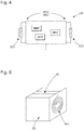
figure 4 représente une unité d'équilibrage d'un système d'équilibrage par transfert d'énergie sans fil selon l'invention, - la
figure 5 représente une cellule embarquant une unité d'équilibrage selon l'invention. - La
figure 3 représente une batterie comprenant des cellules C1-C3 montées en série et formant une batterie, et un système d'équilibrage SE de ladite batterie selon l'invention. Le système d'équilibrage comporte une pluralité d'éléments dissipatifs D1-D3 et une pluralité d'unités d'équilibrage U1-U3. A chaque cellule est associée un élément dissipatif et une unité d'équilibrage. On note que dans l'exemple décrit, les cellules, les éléments dissipatifs et les unités d'équilibrage sont chacun au nombre de trois, mais naturellement ce nombre n'est pas limitatif. - Chaque élément dissipatif est composé d'un MOSFET dont le drain et la source sont branchés de part et d'autre de la cellule associée, et dont la grille est connectée à l'unité d'équilibrage associée. Toutefois, l'élément dissipatif pourrait être n'importe quel élément capable de court-circuiter la cellule (par exemple une résistance, un interrupteur, un commutateur, un transistor bipolaire...) lorsque celle-ci est chargée.
- Chaque unité d'équilibrage fonctionne de manière autonome lors d'une affectation à une cellule. Le système d'équilibrage selon l'invention est complètement décentralisé. A titre d'exemple, la
figure 4 représente l'unité d'équilibrage U2, étant entendu que les autres unités sont identiques. L'unité d'équilibrage U2 comporte : - des moyens de contrôle MC2 de l'élément dissipatif D2 associé,
- des moyens de mesure MM2 de paramètres d'état de la cellule C2 associée,
- des moyens de communication sans fil MD2 avec les unités d'équilibrage U1, U3 affectées aux cellules adjacentes C1, C3, permettant notamment d'envoyer et de recevoir des paramètres d'état,
- des moyens de transfert d'énergie sans fil ME2 avec les unités d'équilibrage U1, U3 affectées aux cellules adjacentes C1, C3,
- une mémoire MU2 comportant des paramètres de réglage de la cellule C2 et un historique d'événements relatifs à la cellule.
- Les moyens de contrôle MC2 permettent de contrôler l'élément dissipatif D2 associé, en court-circuitant ou non la cellule C2 associée.
- Les moyens de mesure MM2 permettent de mesurer des paramètres d'état qui comprennent notamment la tension de la cellule C2 associée, le courant parcourant l'élément dissipatif D2, et la température de la cellule C2.
- Les moyens de communication MD2 permettent à l'unité d'équilibrage U2 d'envoyer ses paramètres d'état aux unités d'équilibrage U1, U3 des cellules adjacentes C1, C3, et par ailleurs de recevoir leurs paramètres d'état. Les moyens de communication MD2 sont donc bidirectionnels. Les moyens de communication MD2 permettent également, dans un mode de réalisation, de recevoir ou envoyer des statuts (indiquant par exemple si une cellule est en cours d'équilibrage) et des commandes.
- Les moyens de transfert d'énergie ME2 permettent à la cellule C2 d'envoyer aux cellules adjacentes C1, C3 de l'énergie de la cellule C2, ou de recevoir de l'énergie provenant des cellules adjacentes C1, C3. Les moyens de transfert d'énergie ME2 sont donc bidirectionnels. Le transfert d'énergie est sans fil, et géré par l'unité d'équilibrage. Les paramètres d'état transmis entre la cellule C2 et les cellules adjacentes C1, C3 permettent de réguler la quantité d'énergie à transmettre.
- Dans l'exemple représenté, les moyens de communication MD2 et de transfert d'énergie ME2 sont de type inductif et sont constitués de deux bobines B21, B23, l'une B21 des deux bobines B21, B23 servant à communiquer avec l'une U1 des deux unités adjacentes U1, U3, l'autre B23 des deux bobines B21, B23 servant à communiquer avec l'autre U3 des deux unités adjacentes U1, U3. Divers fréquences sont utilisées pour la communication de données et le transfert d'énergie. On note que d'autres types de couplage que le couplage inductif entre les unités d'équilibrage sont possibles. Le document « A review on the recent development of capacitive wireless power transfer technology » de Fei Lu, décrit, notamment en référence à sa
figure 2 , différents types de couplages possibles. - La mémoire MU2 comporte des paramètres de réglage de la cellule C2. Les paramètres de réglage comportent des paramètres d'usine propres à la production de la batterie, par exemple son numéro d'identification, et des paramètres pour l'équilibrage, par exemple une tension minimale et maximale de décharge et de charge ou encore une table de correspondance de l'état de charge en fonction de la tension de la cellule. La mémoire MU2 comporte également un historique d'événements de la cellule C2 survenus tout au long de sa durée de vie, par exemple la durée d'utilisation de la cellule, des alertes, des mauvaises manipulations électriques de la cellule, etc. La mémoire est une zone protégée, on peut considérer qu'il s'agit d'un coffre-fort de données. Seuls l'unité d'équilibrage U2 elle-même et le fabriquant ont accès à la mémoire MU2 et peuvent modifier les données qu'elle contient. L'unité d'équilibrage U2 peut par exemple être posée sur un support dédié sans fil qui permet d'accéder, via les moyens de communication MD2, à la mémoire MU2.
- L'ensemble cellule C2, élément de dissipation D2 et unité d'équilibrage U2 forme un ensemble compact, comme illustré à la
figure 5 . L'unité d'équilibrage U2 est embarquée dans la cellule C2. Lafigure 5 représente la cellule C2, de part et d'autre de laquelle sont plaquées les deux bobines B21, B23, les deux bobines étant reliées à l'unité d'équilibrage U2 montée sur un circuit imprimé flexible. Cette disposition garantit une symétrie de structure permettant de ne pas avoir à se soucier de l'orientation de l'ensemble, lors de son montage ou son remplacement. La miniaturisation du système permet de minimiser son impact en termes de volume et de poids. Les bobines B21, B31 sont mécaniquement positionnées pour garantir un rendement de transfert d'énergie optimal. - Le système d'équilibrage selon l'invention présente de nombreux avantages, entre autres :
- il est modulable, c'est-à-dire il permet l'ajout d'un nombre indéfini de cellules en série,
- il permet une utilisation dans les états actifs (charge et décharge) et de repos de la cellule,
- il permet la communication entre cellules adjacentes pour l'adaptation des niveaux d'énergie et l'échange de données,
- il permet, par une communication sans fil chaînée entre toutes les cellules mises en série, de transférer des commandes ou des informations à plusieurs cellules,
- il permet d'optimiser le transfert d'énergie par un alignement mécanique des cellules de la batterie,
- les distances entre les cellules étant relativement courtes, le rendement du transfert d'énergie est amélioré,
- il permet un accès à distance à chaque cellule pour connaître (et éventuellement modifier) ses caractéristiques et informations de paramétrage,
- il optimise la communication entre cellules de l'équilibrage, à travers le couplage, et
- il permet une stabilité mécanique et de positionnement des éléments de transfert d'énergie.
- Bien entendu, la présente invention ne se limite pas à l'exemple illustré et est susceptible de diverses variantes et modifications qui apparaîtront à l'homme de l'art.
Claims (10)
- Unité d'équilibrage (U2) embarquée sur une cellule (C2) de batterie, et comprenant :- des moyens de mesure (MM2) de paramètres d'état de la cellule (C2),- des moyens de communication (MD2) sans fil, permettant d'envoyer et de recevoir des paramètres d'état,- des moyens de transfert d'énergie (ME2) sans fil.
- Unité d'équilibrage (U2) selon la revendication précédente, les moyens de communication (MD2) et les moyens de transfert d'énergie (ME2) étant les mêmes.
- Unité d'équilibrage (U2) selon la revendication précédente, les moyens de communication (MD2) et les moyens de transfert d'énergie (ME2) étant de type inductif, notamment constitués de deux bobines (B21, B23) disposées de part et d'autre de la cellule (C2).
- Unité d'équilibrage (U2) selon l'une des revendications précédentes, les paramètres d'état d'une cellule (C2) comportant des mesures d'une tension et d'une température de la cellule, et un statut de fonctionnement de la cellule.
- Unité d'équilibrage (U2) selon l'une des revendications précédentes, les paramètres d'état d'une cellule (C2) comportant une durée de fonctionnement de la cellule.
- Unité d'équilibrage (U2) selon l'une des revendications précédentes, comprenant une mémoire (MU2) comportant des paramètres de réglage de la cellule (C2) et un historique d'événements relatifs à la cellule (C2).
- Système d'équilibrage (SE) de cellules (C1, C2, C3) de batterie connectées en série, comportant une pluralité d'unités d'équilibrage (U1, U2, U3) selon l'une des revendications précédentes, chaque unité d'équilibrage (U1, U2, U3) étant embarquée sur une cellule (C1, C2, C3) de la batterie, les moyens de communication (MD2) de chaque unité d'équilibrage (U2) permettant d'envoyer ses paramètres d'état aux unités d'équilibrage adjacentes (U1, U3) et de recevoir les paramètres d'état des unités d'équilibrage adjacentes (U1, U3), les moyens de transfert d'énergie (ME2) de chaque unité d'équilibrage (U2) permettant d'envoyer de l'énergie aux unités d'équilibrage adjacentes (U1, U3) ou de recevoir de l'énergie provenant des unités d'équilibrage adjacentes (U1, U3).
- Système d'équilibrage (SE) selon la revendication précédente, comportant une pluralité d'éléments dissipatifs (D1, D2, D3), chaque élément dissipatif (D1, D2, D3) étant affecté à une cellule (C1, C2, C3) et connecté en parallèle de ladite cellule, et l'unité d'équilibrage (U2) embarqué sur ladite cellule (C2) comporte des moyens de contrôle (MC2) de l'élément dissipatif (D2).
- Système d'équilibrage (SE) selon la revendication précédente, les paramètres d'état d'une cellule (C1, C2, C3) comportant une mesure du courant dans l'élément dissipatif (D1, D2, D3) connecté en parallèle de ladite cellule.
- Système d'équilibrage selon l'une des revendications 8 ou 9, chaque élément dissipatif (D1, D2, D3) étant constitué d'un transistor à effet de champ à grille métal-oxyde dont le drain et la source sont branchés de part et d'autre de la cellule (C1, C2, C3), et la grille est connectée à l'unité d'équilibrage (U1, U2, U3).
Priority Applications (13)
| Application Number | Priority Date | Filing Date | Title |
|---|---|---|---|
| ES18186368T ES2884140T3 (es) | 2018-07-30 | 2018-07-30 | Unidad y sistema de equilibrado inalámbrico para celda de batería |
| SI201830388T SI3605778T1 (sl) | 2018-07-30 | 2018-07-30 | Brezžična izravnalna enota in sistem za baterijsko celico |
| HUE18186368A HUE055639T2 (hu) | 2018-07-30 | 2018-07-30 | Vezeték nélküli kiegyenlítõ egység és rendszer akkumulátor cellához |
| RS20211105A RS62308B1 (sr) | 2018-07-30 | 2018-07-30 | Bežična jedinica i sistem za balansiranje baterijske ćelije |
| PL18186368T PL3605778T3 (pl) | 2018-07-30 | 2018-07-30 | Bezprzewodowe jednostka i system do wyważania dla ogniw akumulatora |
| EP18186368.9A EP3605778B1 (fr) | 2018-07-30 | 2018-07-30 | Unité et système d'équilibrage sans fil pour cellule de batterie |
| PT181863689T PT3605778T (pt) | 2018-07-30 | 2018-07-30 | Unidade e sistema de balanceamento sem fios para célula de bateria |
| US16/441,090 US11495994B2 (en) | 2018-07-30 | 2019-06-14 | Unit and system for wireless balancing for battery cell |
| JP2019124347A JP6850322B2 (ja) | 2018-07-30 | 2019-07-03 | 電池のセルを無線を用いて平衡化するユニット及びシステム |
| KR1020190087900A KR102240207B1 (ko) | 2018-07-30 | 2019-07-19 | 배터리 셀에 대한 무선 밸런싱을 위한 유닛 및 시스템 |
| CN202411899122.9A CN119727030A (zh) | 2018-07-30 | 2019-07-26 | 用于电池组电池的无线平衡的单元和系统 |
| CN201910680406.1A CN110783974A (zh) | 2018-07-30 | 2019-07-26 | 用于电池组电池的无线平衡的单元和系统 |
| HRP20211367TT HRP20211367T1 (hr) | 2018-07-30 | 2021-08-27 | Bežična jedinica za uravnoteženje i sustav za baterijsku ćeliju |
Applications Claiming Priority (1)
| Application Number | Priority Date | Filing Date | Title |
|---|---|---|---|
| EP18186368.9A EP3605778B1 (fr) | 2018-07-30 | 2018-07-30 | Unité et système d'équilibrage sans fil pour cellule de batterie |
Publications (2)
| Publication Number | Publication Date |
|---|---|
| EP3605778A1 true EP3605778A1 (fr) | 2020-02-05 |
| EP3605778B1 EP3605778B1 (fr) | 2021-06-16 |
Family
ID=63103845
Family Applications (1)
| Application Number | Title | Priority Date | Filing Date |
|---|---|---|---|
| EP18186368.9A Active EP3605778B1 (fr) | 2018-07-30 | 2018-07-30 | Unité et système d'équilibrage sans fil pour cellule de batterie |
Country Status (12)
| Country | Link |
|---|---|
| US (1) | US11495994B2 (fr) |
| EP (1) | EP3605778B1 (fr) |
| JP (1) | JP6850322B2 (fr) |
| KR (1) | KR102240207B1 (fr) |
| CN (2) | CN119727030A (fr) |
| ES (1) | ES2884140T3 (fr) |
| HR (1) | HRP20211367T1 (fr) |
| HU (1) | HUE055639T2 (fr) |
| PL (1) | PL3605778T3 (fr) |
| PT (1) | PT3605778T (fr) |
| RS (1) | RS62308B1 (fr) |
| SI (1) | SI3605778T1 (fr) |
Families Citing this family (5)
| Publication number | Priority date | Publication date | Assignee | Title |
|---|---|---|---|---|
| US11718198B2 (en) | 2020-02-08 | 2023-08-08 | Yongxin Wang | Power supply system for electric vehicles |
| KR102882654B1 (ko) | 2020-06-15 | 2025-11-07 | 주식회사 엘지에너지솔루션 | 무선 충전을 위한 배터리 관리 시스템 및 배터리 랙 |
| KR20220157004A (ko) | 2021-05-20 | 2022-11-29 | 목포대학교산학협력단 | 무선 에너지 전송을 이용한 셀 밸런싱 장치 |
| EP4376154B1 (fr) | 2022-11-28 | 2024-10-23 | Renesas Design Austria GmbH | Équilibrage d'éléments de batterie basé sur une charge sans fil |
| EP4535500A1 (fr) | 2023-10-06 | 2025-04-09 | Belenos Clean Power Holding AG | Élément de batterie approprié pour la communication sans fil de signaux de données, batterie comprenant au moins un élément |
Citations (4)
| Publication number | Priority date | Publication date | Assignee | Title |
|---|---|---|---|---|
| US6100663A (en) * | 1996-05-03 | 2000-08-08 | Auckland Uniservices Limited | Inductively powered battery charger |
| US20140055096A1 (en) * | 2012-08-24 | 2014-02-27 | Snu R&Db Foundation | Battery pack, battery apparatus including the same, and cell balancing method thereof |
| US20150188358A1 (en) * | 2013-12-30 | 2015-07-02 | Samsung Electro-Mechanics Co., Ltd. | Non-contact power supply apparatus, charging apparatus, and battery apparatus |
| US20160336765A1 (en) * | 2014-01-07 | 2016-11-17 | Utah State University | Model predictive control and optimization for battery charging and discharging |
Family Cites Families (15)
| Publication number | Priority date | Publication date | Assignee | Title |
|---|---|---|---|---|
| CN102427963A (zh) * | 2009-05-19 | 2012-04-25 | 沃尔沃拉斯特瓦格纳公司 | 用于驱动电动机的模块化能量存储系统 |
| FR2963709B1 (fr) * | 2010-08-05 | 2014-12-26 | E4V | Procede d'equilibrage pour batterie electrique et systeme de gestion pour batterie mettant en oeuvre un tel procede |
| CN103270666B (zh) * | 2010-11-02 | 2018-01-30 | 纳维达斯解决方案有限公司 | 用于智能电池管理的无线电池区域网络 |
| JP5901180B2 (ja) | 2011-08-31 | 2016-04-06 | キヤノン株式会社 | 透過型x線発生装置及びそれを用いたx線撮影装置 |
| EP3699617B1 (fr) * | 2011-10-07 | 2024-02-07 | Hitachi Astemo, Ltd. | Appareil et système de surveillance de batterie |
| US20140091623A1 (en) * | 2012-09-28 | 2014-04-03 | Keith Shippy | Power share controller |
| KR102201102B1 (ko) * | 2013-03-15 | 2021-01-12 | 디자인 플럭스 테크놀로지스, 엘엘씨 | 동적으로 재구성가능한 에너지 스토리지 장치를 생성하기 위한 방법 및 장치 |
| CN103199587B (zh) * | 2013-04-03 | 2015-12-09 | 深圳市航盛电子股份有限公司 | 利用无线充电实现新能源汽车电池主动均衡的方法及系统 |
| JP6196861B2 (ja) * | 2013-09-20 | 2017-09-13 | 日立マクセル株式会社 | モバイルバッテリ |
| CN106300690A (zh) * | 2015-06-12 | 2017-01-04 | 西安中兴新软件有限责任公司 | 一种无线充电方法、设备及终端 |
| JP6819233B2 (ja) * | 2016-11-17 | 2021-01-27 | 株式会社オートネットワーク技術研究所 | 車両用のバッテリ監視システム |
| KR20180087544A (ko) * | 2017-01-24 | 2018-08-02 | (주) 제이앤케이사이언스 | 무선 통신이 가능한 배터리 |
| KR102217590B1 (ko) * | 2018-07-16 | 2021-02-18 | 주식회사 엘지화학 | 배터리 밸런싱 장치 및 방법 |
| US11056891B2 (en) * | 2018-07-18 | 2021-07-06 | Nxp Usa, Inc. | Battery stack monitoring and balancing circuit |
| CN110518709A (zh) * | 2019-09-02 | 2019-11-29 | 北京酷能科技有限公司 | 一种无线充电装置、方法和无线接收装置、方法 |
-
2018
- 2018-07-30 ES ES18186368T patent/ES2884140T3/es active Active
- 2018-07-30 EP EP18186368.9A patent/EP3605778B1/fr active Active
- 2018-07-30 SI SI201830388T patent/SI3605778T1/sl unknown
- 2018-07-30 PL PL18186368T patent/PL3605778T3/pl unknown
- 2018-07-30 RS RS20211105A patent/RS62308B1/sr unknown
- 2018-07-30 PT PT181863689T patent/PT3605778T/pt unknown
- 2018-07-30 HU HUE18186368A patent/HUE055639T2/hu unknown
-
2019
- 2019-06-14 US US16/441,090 patent/US11495994B2/en active Active
- 2019-07-03 JP JP2019124347A patent/JP6850322B2/ja active Active
- 2019-07-19 KR KR1020190087900A patent/KR102240207B1/ko active Active
- 2019-07-26 CN CN202411899122.9A patent/CN119727030A/zh active Pending
- 2019-07-26 CN CN201910680406.1A patent/CN110783974A/zh active Pending
-
2021
- 2021-08-27 HR HRP20211367TT patent/HRP20211367T1/hr unknown
Patent Citations (4)
| Publication number | Priority date | Publication date | Assignee | Title |
|---|---|---|---|---|
| US6100663A (en) * | 1996-05-03 | 2000-08-08 | Auckland Uniservices Limited | Inductively powered battery charger |
| US20140055096A1 (en) * | 2012-08-24 | 2014-02-27 | Snu R&Db Foundation | Battery pack, battery apparatus including the same, and cell balancing method thereof |
| US20150188358A1 (en) * | 2013-12-30 | 2015-07-02 | Samsung Electro-Mechanics Co., Ltd. | Non-contact power supply apparatus, charging apparatus, and battery apparatus |
| US20160336765A1 (en) * | 2014-01-07 | 2016-11-17 | Utah State University | Model predictive control and optimization for battery charging and discharging |
Also Published As
| Publication number | Publication date |
|---|---|
| US20200036196A1 (en) | 2020-01-30 |
| PT3605778T (pt) | 2021-08-24 |
| KR102240207B1 (ko) | 2021-04-14 |
| HUE055639T2 (hu) | 2021-12-28 |
| SI3605778T1 (sl) | 2021-10-29 |
| PL3605778T3 (pl) | 2021-12-13 |
| EP3605778B1 (fr) | 2021-06-16 |
| RS62308B1 (sr) | 2021-09-30 |
| KR20200013592A (ko) | 2020-02-07 |
| US11495994B2 (en) | 2022-11-08 |
| JP6850322B2 (ja) | 2021-03-31 |
| HRP20211367T1 (hr) | 2021-11-26 |
| JP2020022345A (ja) | 2020-02-06 |
| ES2884140T3 (es) | 2021-12-10 |
| CN110783974A (zh) | 2020-02-11 |
| CN119727030A (zh) | 2025-03-28 |
Similar Documents
| Publication | Publication Date | Title |
|---|---|---|
| EP3605778B1 (fr) | Unité et système d'équilibrage sans fil pour cellule de batterie | |
| FR2973963A1 (fr) | Dispositif de transfert de charge et procede de gestion associe | |
| CA3235014A1 (fr) | Procedes d'utilisation d'une charge bidirectionnelle servant a fournir une puissance de secours et a augmenter la resilience de reseaux alimentes | |
| EP3033821B1 (fr) | Dispositif de commutation et protection a distance de systemes electriques | |
| FR2904486A1 (fr) | Procede et systeme de gestion et de modulation en temps reel de consommation electrique. | |
| CH715210B1 (fr) | Unité et système d'équilibrage sans fil pour cellule de batterie. | |
| WO2012126855A2 (fr) | Gestion centralisee de l'alimentation en energie d'une pluralite de reseaux locaux d'energie | |
| EP3451361B1 (fr) | Dispositif de commutation électrique et procédés de configuration et de diagnostic associés | |
| EP2220742A2 (fr) | Procede de gestion et systeme de stockage d'energie electrique | |
| EP1753112A1 (fr) | Système et procédé de contrôle d'une batterie rechargeable | |
| EP3107245B1 (fr) | Dispositif d'alimentation et de transmission de données, procédé et bâtiment associés | |
| CA3238858A1 (fr) | Alimentation electrique intelligente pour chargeurs de vehicules electriques | |
| CA3238796A1 (fr) | Systeme intelligent de charge de vehicules electriques a batteries avec multiples prises d'entree et multiples prises de sortie | |
| WO2022180346A1 (fr) | Dispositif de stockage et de génération concomitante d'au moins une tension électrique, et procédé de gestion associé | |
| EP3975364B1 (fr) | Dispositif de gestion d'alimentation en énergie, système, procédé et programme d'ordinateur associés | |
| FR3085153A1 (fr) | Procede de protection d'une charge associee a une voie de disjonction d'une carte electronique de disjoncteurs statiques | |
| EP3293914B1 (fr) | Commutateur reseau a alimentation sauvegardee | |
| FR3056050B1 (fr) | Commutateur reseau avec poe | |
| FR3056051B1 (fr) | Commutateur reseau a alimentation sauvegardee | |
| EP4066340B1 (fr) | Micro-réseau résilient d'appareils de chauffage de type radiateur électrique | |
| CN111164639A (zh) | 设备管理系统和设备管理方法 | |
| WO2020039143A1 (fr) | Procédé d'auto-configuration d'une carte électronique autonome de disjoncteurs statiques | |
| EP4466773A1 (fr) | Procédé de commande d'une batterie électrique | |
| WO2025211061A1 (fr) | Procédé, dispositif et programme de traitement d'informations | |
| FR3030997A1 (fr) | Controleur d'alimentation pour reseau de distribution d'energie electrique et procede de fabrication d'un tel controleur |
Legal Events
| Date | Code | Title | Description |
|---|---|---|---|
| PUAI | Public reference made under article 153(3) epc to a published international application that has entered the european phase |
Free format text: ORIGINAL CODE: 0009012 |
|
| STAA | Information on the status of an ep patent application or granted ep patent |
Free format text: STATUS: THE APPLICATION HAS BEEN PUBLISHED |
|
| AK | Designated contracting states |
Kind code of ref document: A1 Designated state(s): AL AT BE BG CH CY CZ DE DK EE ES FI FR GB GR HR HU IE IS IT LI LT LU LV MC MK MT NL NO PL PT RO RS SE SI SK SM TR |
|
| AX | Request for extension of the european patent |
Extension state: BA ME |
|
| STAA | Information on the status of an ep patent application or granted ep patent |
Free format text: STATUS: REQUEST FOR EXAMINATION WAS MADE |
|
| 17P | Request for examination filed |
Effective date: 20200805 |
|
| RBV | Designated contracting states (corrected) |
Designated state(s): AL AT BE BG CH CY CZ DE DK EE ES FI FR GB GR HR HU IE IS IT LI LT LU LV MC MK MT NL NO PL PT RO RS SE SI SK SM TR |
|
| RIC1 | Information provided on ipc code assigned before grant |
Ipc: H02J 7/00 20060101AFI20201030BHEP Ipc: B60L 58/22 20190101ALI20201030BHEP |
|
| GRAP | Despatch of communication of intention to grant a patent |
Free format text: ORIGINAL CODE: EPIDOSNIGR1 |
|
| STAA | Information on the status of an ep patent application or granted ep patent |
Free format text: STATUS: GRANT OF PATENT IS INTENDED |
|
| INTG | Intention to grant announced |
Effective date: 20210209 |
|
| GRAS | Grant fee paid |
Free format text: ORIGINAL CODE: EPIDOSNIGR3 |
|
| GRAA | (expected) grant |
Free format text: ORIGINAL CODE: 0009210 |
|
| STAA | Information on the status of an ep patent application or granted ep patent |
Free format text: STATUS: THE PATENT HAS BEEN GRANTED |
|
| AK | Designated contracting states |
Kind code of ref document: B1 Designated state(s): AL AT BE BG CH CY CZ DE DK EE ES FI FR GB GR HR HU IE IS IT LI LT LU LV MC MK MT NL NO PL PT RO RS SE SI SK SM TR |
|
| REG | Reference to a national code |
Ref country code: GB Ref legal event code: FG4D Free format text: NOT ENGLISH |
|
| REG | Reference to a national code |
Ref country code: CH Ref legal event code: EP |
|
| REG | Reference to a national code |
Ref country code: DE Ref legal event code: R096 Ref document number: 602018018565 Country of ref document: DE |
|
| REG | Reference to a national code |
Ref country code: AT Ref legal event code: REF Ref document number: 1403140 Country of ref document: AT Kind code of ref document: T Effective date: 20210715 |
|
| REG | Reference to a national code |
Ref country code: IE Ref legal event code: FG4D Free format text: LANGUAGE OF EP DOCUMENT: FRENCH |
|
| REG | Reference to a national code |
Ref country code: NL Ref legal event code: FP |
|
| REG | Reference to a national code |
Ref country code: PT Ref legal event code: SC4A Ref document number: 3605778 Country of ref document: PT Date of ref document: 20210824 Kind code of ref document: T Free format text: AVAILABILITY OF NATIONAL TRANSLATION Effective date: 20210816 |
|
| REG | Reference to a national code |
Ref country code: HR Ref legal event code: TUEP Ref document number: P20211367 Country of ref document: HR |
|
| REG | Reference to a national code |
Ref country code: SE Ref legal event code: TRGR |
|
| REG | Reference to a national code |
Ref country code: FI Ref legal event code: FGE |
|
| REG | Reference to a national code |
Ref country code: RO Ref legal event code: EPE |
|
| REG | Reference to a national code |
Ref country code: NO Ref legal event code: T2 Effective date: 20210616 Ref country code: LT Ref legal event code: MG9D |
|
| REG | Reference to a national code |
Ref country code: SK Ref legal event code: T3 Ref document number: E 38011 Country of ref document: SK |
|
| PG25 | Lapsed in a contracting state [announced via postgrant information from national office to epo] |
Ref country code: LT Free format text: LAPSE BECAUSE OF FAILURE TO SUBMIT A TRANSLATION OF THE DESCRIPTION OR TO PAY THE FEE WITHIN THE PRESCRIBED TIME-LIMIT Effective date: 20210616 Ref country code: BG Free format text: LAPSE BECAUSE OF FAILURE TO SUBMIT A TRANSLATION OF THE DESCRIPTION OR TO PAY THE FEE WITHIN THE PRESCRIBED TIME-LIMIT Effective date: 20210916 |
|
| REG | Reference to a national code |
Ref country code: HR Ref legal event code: ODRP Ref document number: P20211367 Country of ref document: HR Payment date: 20210901 Year of fee payment: 4 |
|
| REG | Reference to a national code |
Ref country code: HR Ref legal event code: T1PR Ref document number: P20211367 Country of ref document: HR |
|
| PG25 | Lapsed in a contracting state [announced via postgrant information from national office to epo] |
Ref country code: GR Free format text: LAPSE BECAUSE OF FAILURE TO SUBMIT A TRANSLATION OF THE DESCRIPTION OR TO PAY THE FEE WITHIN THE PRESCRIBED TIME-LIMIT Effective date: 20210917 Ref country code: LV Free format text: LAPSE BECAUSE OF FAILURE TO SUBMIT A TRANSLATION OF THE DESCRIPTION OR TO PAY THE FEE WITHIN THE PRESCRIBED TIME-LIMIT Effective date: 20210616 |
|
| REG | Reference to a national code |
Ref country code: ES Ref legal event code: FG2A Ref document number: 2884140 Country of ref document: ES Kind code of ref document: T3 Effective date: 20211210 |
|
| REG | Reference to a national code |
Ref country code: HU Ref legal event code: AG4A Ref document number: E055639 Country of ref document: HU |
|
| PG25 | Lapsed in a contracting state [announced via postgrant information from national office to epo] |
Ref country code: EE Free format text: LAPSE BECAUSE OF FAILURE TO SUBMIT A TRANSLATION OF THE DESCRIPTION OR TO PAY THE FEE WITHIN THE PRESCRIBED TIME-LIMIT Effective date: 20210616 Ref country code: SM Free format text: LAPSE BECAUSE OF FAILURE TO SUBMIT A TRANSLATION OF THE DESCRIPTION OR TO PAY THE FEE WITHIN THE PRESCRIBED TIME-LIMIT Effective date: 20210616 |
|
| REG | Reference to a national code |
Ref country code: DE Ref legal event code: R097 Ref document number: 602018018565 Country of ref document: DE |
|
| PG25 | Lapsed in a contracting state [announced via postgrant information from national office to epo] |
Ref country code: MC Free format text: LAPSE BECAUSE OF FAILURE TO SUBMIT A TRANSLATION OF THE DESCRIPTION OR TO PAY THE FEE WITHIN THE PRESCRIBED TIME-LIMIT Effective date: 20210616 |
|
| PLBE | No opposition filed within time limit |
Free format text: ORIGINAL CODE: 0009261 |
|
| STAA | Information on the status of an ep patent application or granted ep patent |
Free format text: STATUS: NO OPPOSITION FILED WITHIN TIME LIMIT |
|
| PG25 | Lapsed in a contracting state [announced via postgrant information from national office to epo] |
Ref country code: DK Free format text: LAPSE BECAUSE OF FAILURE TO SUBMIT A TRANSLATION OF THE DESCRIPTION OR TO PAY THE FEE WITHIN THE PRESCRIBED TIME-LIMIT Effective date: 20210616 |
|
| 26N | No opposition filed |
Effective date: 20220317 |
|
| PG25 | Lapsed in a contracting state [announced via postgrant information from national office to epo] |
Ref country code: LU Free format text: LAPSE BECAUSE OF NON-PAYMENT OF DUE FEES Effective date: 20210730 Ref country code: AL Free format text: LAPSE BECAUSE OF FAILURE TO SUBMIT A TRANSLATION OF THE DESCRIPTION OR TO PAY THE FEE WITHIN THE PRESCRIBED TIME-LIMIT Effective date: 20210616 |
|
| PG25 | Lapsed in a contracting state [announced via postgrant information from national office to epo] |
Ref country code: IE Free format text: LAPSE BECAUSE OF NON-PAYMENT OF DUE FEES Effective date: 20210730 |
|
| REG | Reference to a national code |
Ref country code: HR Ref legal event code: ODRP Ref document number: P20211367 Country of ref document: HR Payment date: 20220729 Year of fee payment: 5 |
|
| REG | Reference to a national code |
Ref country code: AT Ref legal event code: UEP Ref document number: 1403140 Country of ref document: AT Kind code of ref document: T Effective date: 20210616 |
|
| PG25 | Lapsed in a contracting state [announced via postgrant information from national office to epo] |
Ref country code: CY Free format text: LAPSE BECAUSE OF FAILURE TO SUBMIT A TRANSLATION OF THE DESCRIPTION OR TO PAY THE FEE WITHIN THE PRESCRIBED TIME-LIMIT Effective date: 20210616 |
|
| REG | Reference to a national code |
Ref country code: HR Ref legal event code: ODRP Ref document number: P20211367 Country of ref document: HR Payment date: 20230720 Year of fee payment: 6 |
|
| P01 | Opt-out of the competence of the unified patent court (upc) registered |
Effective date: 20230718 |
|
| PGFP | Annual fee paid to national office [announced via postgrant information from national office to epo] |
Ref country code: TR Payment date: 20230626 Year of fee payment: 6 |
|
| PG25 | Lapsed in a contracting state [announced via postgrant information from national office to epo] |
Ref country code: MK Free format text: LAPSE BECAUSE OF FAILURE TO SUBMIT A TRANSLATION OF THE DESCRIPTION OR TO PAY THE FEE WITHIN THE PRESCRIBED TIME-LIMIT Effective date: 20210616 |
|
| REG | Reference to a national code |
Ref country code: HR Ref legal event code: ODRP Ref document number: P20211367 Country of ref document: HR Payment date: 20240709 Year of fee payment: 7 |
|
| PG25 | Lapsed in a contracting state [announced via postgrant information from national office to epo] |
Ref country code: MT Free format text: LAPSE BECAUSE OF FAILURE TO SUBMIT A TRANSLATION OF THE DESCRIPTION OR TO PAY THE FEE WITHIN THE PRESCRIBED TIME-LIMIT Effective date: 20210616 |
|
| PGFP | Annual fee paid to national office [announced via postgrant information from national office to epo] |
Ref country code: FI Payment date: 20250620 Year of fee payment: 8 |
|
| PGFP | Annual fee paid to national office [announced via postgrant information from national office to epo] |
Ref country code: PL Payment date: 20250626 Year of fee payment: 8 |
|
| PGFP | Annual fee paid to national office [announced via postgrant information from national office to epo] |
Ref country code: GB Payment date: 20250619 Year of fee payment: 8 |
|
| PGFP | Annual fee paid to national office [announced via postgrant information from national office to epo] |
Ref country code: NO Payment date: 20250623 Year of fee payment: 8 |
|
| PGFP | Annual fee paid to national office [announced via postgrant information from national office to epo] |
Ref country code: NL Payment date: 20250620 Year of fee payment: 8 Ref country code: BE Payment date: 20250619 Year of fee payment: 8 |
|
| PGFP | Annual fee paid to national office [announced via postgrant information from national office to epo] |
Ref country code: PT Payment date: 20250624 Year of fee payment: 8 |
|
| PGFP | Annual fee paid to national office [announced via postgrant information from national office to epo] |
Ref country code: FR Payment date: 20250620 Year of fee payment: 8 |
|
| PGFP | Annual fee paid to national office [announced via postgrant information from national office to epo] |
Ref country code: SK Payment date: 20250625 Year of fee payment: 8 |
|
| PGFP | Annual fee paid to national office [announced via postgrant information from national office to epo] |
Ref country code: SI Payment date: 20250627 Year of fee payment: 8 Ref country code: SE Payment date: 20250619 Year of fee payment: 8 |
|
| REG | Reference to a national code |
Ref country code: HR Ref legal event code: ODRP Ref document number: P20211367 Country of ref document: HR Payment date: 20250710 Year of fee payment: 8 |
|
| PGFP | Annual fee paid to national office [announced via postgrant information from national office to epo] |
Ref country code: HU Payment date: 20250714 Year of fee payment: 8 |
|
| PGFP | Annual fee paid to national office [announced via postgrant information from national office to epo] |
Ref country code: ES Payment date: 20250801 Year of fee payment: 8 |
|
| PGFP | Annual fee paid to national office [announced via postgrant information from national office to epo] |
Ref country code: DE Payment date: 20250620 Year of fee payment: 8 |
|
| PGFP | Annual fee paid to national office [announced via postgrant information from national office to epo] |
Ref country code: IT Payment date: 20250619 Year of fee payment: 8 |
|
| PGFP | Annual fee paid to national office [announced via postgrant information from national office to epo] |
Ref country code: HR Payment date: 20250710 Year of fee payment: 8 |
|
| PGFP | Annual fee paid to national office [announced via postgrant information from national office to epo] |
Ref country code: AT Payment date: 20250623 Year of fee payment: 8 |
|
| PGFP | Annual fee paid to national office [announced via postgrant information from national office to epo] |
Ref country code: CH Payment date: 20250801 Year of fee payment: 8 |
|
| PGFP | Annual fee paid to national office [announced via postgrant information from national office to epo] |
Ref country code: CZ Payment date: 20250701 Year of fee payment: 8 Ref country code: RS Payment date: 20250711 Year of fee payment: 8 |
|
| PGFP | Annual fee paid to national office [announced via postgrant information from national office to epo] |
Ref country code: RO Payment date: 20250721 Year of fee payment: 8 |