EP3605746B1 - Plug connector and connection with such a connector - Google Patents
Plug connector and connection with such a connector Download PDFInfo
- Publication number
- EP3605746B1 EP3605746B1 EP19188732.2A EP19188732A EP3605746B1 EP 3605746 B1 EP3605746 B1 EP 3605746B1 EP 19188732 A EP19188732 A EP 19188732A EP 3605746 B1 EP3605746 B1 EP 3605746B1
- Authority
- EP
- European Patent Office
- Prior art keywords
- conductor
- plug connector
- connector
- plug
- housing
- Prior art date
- Legal status (The legal status is an assumption and is not a legal conclusion. Google has not performed a legal analysis and makes no representation as to the accuracy of the status listed.)
- Active
Links
- 239000004020 conductor Substances 0.000 claims description 136
- 238000003780 insertion Methods 0.000 description 8
- 230000037431 insertion Effects 0.000 description 8
- 238000005452 bending Methods 0.000 description 5
- 210000002105 tongue Anatomy 0.000 description 5
- 238000013461 design Methods 0.000 description 4
- 230000005540 biological transmission Effects 0.000 description 3
- 239000013013 elastic material Substances 0.000 description 3
- 229910052782 aluminium Inorganic materials 0.000 description 2
- XAGFODPZIPBFFR-UHFFFAOYSA-N aluminium Chemical compound [Al] XAGFODPZIPBFFR-UHFFFAOYSA-N 0.000 description 2
- 238000001746 injection moulding Methods 0.000 description 2
- 230000013011 mating Effects 0.000 description 2
- 230000008878 coupling Effects 0.000 description 1
- 238000010168 coupling process Methods 0.000 description 1
- 238000005859 coupling reaction Methods 0.000 description 1
- 230000001419 dependent effect Effects 0.000 description 1
- 238000011161 development Methods 0.000 description 1
- 230000018109 developmental process Effects 0.000 description 1
- 230000005489 elastic deformation Effects 0.000 description 1
- 238000004519 manufacturing process Methods 0.000 description 1
- 239000000463 material Substances 0.000 description 1
- 229910052751 metal Inorganic materials 0.000 description 1
- 239000002184 metal Substances 0.000 description 1
- 238000000034 method Methods 0.000 description 1
- 230000002028 premature Effects 0.000 description 1
- 230000001737 promoting effect Effects 0.000 description 1
- 238000000926 separation method Methods 0.000 description 1
- 238000012546 transfer Methods 0.000 description 1
Images


Classifications
-
- H—ELECTRICITY
- H01—ELECTRIC ELEMENTS
- H01R—ELECTRICALLY-CONDUCTIVE CONNECTIONS; STRUCTURAL ASSOCIATIONS OF A PLURALITY OF MUTUALLY-INSULATED ELECTRICAL CONNECTING ELEMENTS; COUPLING DEVICES; CURRENT COLLECTORS
- H01R24/00—Two-part coupling devices, or either of their cooperating parts, characterised by their overall structure
- H01R24/38—Two-part coupling devices, or either of their cooperating parts, characterised by their overall structure having concentrically or coaxially arranged contacts
- H01R24/40—Two-part coupling devices, or either of their cooperating parts, characterised by their overall structure having concentrically or coaxially arranged contacts specially adapted for high frequency
-
- H—ELECTRICITY
- H01—ELECTRIC ELEMENTS
- H01R—ELECTRICALLY-CONDUCTIVE CONNECTIONS; STRUCTURAL ASSOCIATIONS OF A PLURALITY OF MUTUALLY-INSULATED ELECTRICAL CONNECTING ELEMENTS; COUPLING DEVICES; CURRENT COLLECTORS
- H01R12/00—Structural associations of a plurality of mutually-insulated electrical connecting elements, specially adapted for printed circuits, e.g. printed circuit boards [PCB], flat or ribbon cables, or like generally planar structures, e.g. terminal strips, terminal blocks; Coupling devices specially adapted for printed circuits, flat or ribbon cables, or like generally planar structures; Terminals specially adapted for contact with, or insertion into, printed circuits, flat or ribbon cables, or like generally planar structures
- H01R12/50—Fixed connections
- H01R12/51—Fixed connections for rigid printed circuits or like structures
- H01R12/55—Fixed connections for rigid printed circuits or like structures characterised by the terminals
- H01R12/58—Fixed connections for rigid printed circuits or like structures characterised by the terminals terminals for insertion into holes
-
- H—ELECTRICITY
- H01—ELECTRIC ELEMENTS
- H01R—ELECTRICALLY-CONDUCTIVE CONNECTIONS; STRUCTURAL ASSOCIATIONS OF A PLURALITY OF MUTUALLY-INSULATED ELECTRICAL CONNECTING ELEMENTS; COUPLING DEVICES; CURRENT COLLECTORS
- H01R12/00—Structural associations of a plurality of mutually-insulated electrical connecting elements, specially adapted for printed circuits, e.g. printed circuit boards [PCB], flat or ribbon cables, or like generally planar structures, e.g. terminal strips, terminal blocks; Coupling devices specially adapted for printed circuits, flat or ribbon cables, or like generally planar structures; Terminals specially adapted for contact with, or insertion into, printed circuits, flat or ribbon cables, or like generally planar structures
- H01R12/70—Coupling devices
- H01R12/71—Coupling devices for rigid printing circuits or like structures
-
- H—ELECTRICITY
- H01—ELECTRIC ELEMENTS
- H01R—ELECTRICALLY-CONDUCTIVE CONNECTIONS; STRUCTURAL ASSOCIATIONS OF A PLURALITY OF MUTUALLY-INSULATED ELECTRICAL CONNECTING ELEMENTS; COUPLING DEVICES; CURRENT COLLECTORS
- H01R12/00—Structural associations of a plurality of mutually-insulated electrical connecting elements, specially adapted for printed circuits, e.g. printed circuit boards [PCB], flat or ribbon cables, or like generally planar structures, e.g. terminal strips, terminal blocks; Coupling devices specially adapted for printed circuits, flat or ribbon cables, or like generally planar structures; Terminals specially adapted for contact with, or insertion into, printed circuits, flat or ribbon cables, or like generally planar structures
- H01R12/70—Coupling devices
- H01R12/91—Coupling devices allowing relative movement between coupling parts, e.g. floating or self aligning
-
- H—ELECTRICITY
- H01—ELECTRIC ELEMENTS
- H01R—ELECTRICALLY-CONDUCTIVE CONNECTIONS; STRUCTURAL ASSOCIATIONS OF A PLURALITY OF MUTUALLY-INSULATED ELECTRICAL CONNECTING ELEMENTS; COUPLING DEVICES; CURRENT COLLECTORS
- H01R13/00—Details of coupling devices of the kinds covered by groups H01R12/70 or H01R24/00 - H01R33/00
- H01R13/62—Means for facilitating engagement or disengagement of coupling parts or for holding them in engagement
- H01R13/629—Additional means for facilitating engagement or disengagement of coupling parts, e.g. aligning or guiding means, levers, gas pressure electrical locking indicators, manufacturing tolerances
- H01R13/631—Additional means for facilitating engagement or disengagement of coupling parts, e.g. aligning or guiding means, levers, gas pressure electrical locking indicators, manufacturing tolerances for engagement only
- H01R13/6315—Additional means for facilitating engagement or disengagement of coupling parts, e.g. aligning or guiding means, levers, gas pressure electrical locking indicators, manufacturing tolerances for engagement only allowing relative movement between coupling parts, e.g. floating connection
-
- H—ELECTRICITY
- H01—ELECTRIC ELEMENTS
- H01R—ELECTRICALLY-CONDUCTIVE CONNECTIONS; STRUCTURAL ASSOCIATIONS OF A PLURALITY OF MUTUALLY-INSULATED ELECTRICAL CONNECTING ELEMENTS; COUPLING DEVICES; CURRENT COLLECTORS
- H01R13/00—Details of coupling devices of the kinds covered by groups H01R12/70 or H01R24/00 - H01R33/00
- H01R13/648—Protective earth or shield arrangements on coupling devices, e.g. anti-static shielding
- H01R13/658—High frequency shielding arrangements, e.g. against EMI [Electro-Magnetic Interference] or EMP [Electro-Magnetic Pulse]
- H01R13/6581—Shield structure
- H01R13/6582—Shield structure with resilient means for engaging mating connector
-
- H—ELECTRICITY
- H01—ELECTRIC ELEMENTS
- H01R—ELECTRICALLY-CONDUCTIVE CONNECTIONS; STRUCTURAL ASSOCIATIONS OF A PLURALITY OF MUTUALLY-INSULATED ELECTRICAL CONNECTING ELEMENTS; COUPLING DEVICES; CURRENT COLLECTORS
- H01R13/00—Details of coupling devices of the kinds covered by groups H01R12/70 or H01R24/00 - H01R33/00
- H01R13/648—Protective earth or shield arrangements on coupling devices, e.g. anti-static shielding
- H01R13/658—High frequency shielding arrangements, e.g. against EMI [Electro-Magnetic Interference] or EMP [Electro-Magnetic Pulse]
- H01R13/6581—Shield structure
- H01R13/6585—Shielding material individually surrounding or interposed between mutually spaced contacts
-
- H—ELECTRICITY
- H01—ELECTRIC ELEMENTS
- H01R—ELECTRICALLY-CONDUCTIVE CONNECTIONS; STRUCTURAL ASSOCIATIONS OF A PLURALITY OF MUTUALLY-INSULATED ELECTRICAL CONNECTING ELEMENTS; COUPLING DEVICES; CURRENT COLLECTORS
- H01R24/00—Two-part coupling devices, or either of their cooperating parts, characterised by their overall structure
- H01R24/38—Two-part coupling devices, or either of their cooperating parts, characterised by their overall structure having concentrically or coaxially arranged contacts
Definitions
- the present invention relates to a connector according to claim 1 and a plug connection with a first connector and a second connector having the features of patent claim 13.
- Plug connections are known in various configurations from the prior art and comprise a first plug connector and a second plug connector, the respective plug connector comprising a housing and at least one conductor, and the respective conductors being brought into electrical contact when the two plug connectors are plugged together in one plugging direction be, whereby the transmission of electrical signals between the conductor of the first connector and the conductor of the second connector is made possible.
- the transmission of the electrical signals should be as loss-free as possible and, on the other hand, the plug connection should enable a horizontal and vertical offset in order to allow tolerances to be compensated for between the two components to be electrically connected.
- coaxial plug-in connectors are typically used in the prior art, which are often designed in multiple parts in a bullet design for the high-frequency range of up to 6 GHz in the SMP design.
- the printed publications constitute further prior art WO 2018/220155 A1 , DE 10 2014 10255 A1 , U.S. 2014 087592 A1 , 30 CN 201 975 540 U , KR 1010 301 772 B1 , and DE 20 2013 006067 U1 .
- the connector according to the invention comprises at least one housing with at least one recess and at least one one-piece conductor, the at least one conductor comprising a first leg with a first end and a second leg with a second end, the second leg of the at least one conductor being partially in the Recess of the housing is held.
- the second leg of the at least one conductor is preferably held firmly on the housing in the area of the second end and more preferably is held firmly on the housing in an electrically insulated manner.
- Between the first limb and At least one spring area is arranged on the second leg, with the first leg or the first end of the conductor being resiliently deflectable by the spring area to compensate for an axial offset.
- the conductor is held firmly supported by the housing at one end in the region of the second leg, the conductor in the region of the first leg is freely movable and resiliently arranged at the other end by the spring region.
- the first leg is preferably freely movable within the recess of the housing.
- the first free end is set up to establish an electrical connection with a second connector and the second end can protrude from the housing in order to establish an electrical connection with an electrical component, in particular a printed circuit board.
- An axis offset can only be compensated for by an elastic deformation of the spring area when the connector is transferred into a plugged-in state using a second connector, without stresses occurring in the elastic material boundaries in the respective conductor.
- the first leg is arranged coaxially to the insertion direction, so that the first leg can be resiliently deflected relative to the second leg by an axial offset by the spring area.
- an axis offset between the respective conductors when transferring to a plugged-in state can be compensated.
- a further advantageous embodiment of the present invention provides that the second leg is arranged at an angle.
- the angle enclosed between the two legs is preferably less than 180°. More preferably, the second leg is arranged at an angle of 135°, even more preferably of 90°, to the first leg, which on the one hand particularly preferably gives the spring area a Allows pivoting movement in an axis perpendicular to the plug-in direction and, more preferably, on the other hand, the at least one conductor can make a cushioned movement in the plug-in direction.
- the spring area can be arranged in an axis to the first leg and the second leg, can have a Z-shape, S-shape, meander shape or any non-linear shape.
- the spring area of the at least one conductor includes at least one bend.
- the at least one bend is preferably formed by a bend with an approximately constant radius, the radius being a multiple of the average diameter of the at least one conductor in the first leg and/or in the second leg.
- the curvature of the at least one conductor is preferably also designed in such a way that the stresses resulting in the conductor when compensating for the axial offset are kept as low as possible and remain within the elastic material limits.
- the at least one conductor is preferably of circular cross-section in the region of the curvature, as a result of which a homogeneous voltage profile results in the at least one conductor in the event of any deflection.
- a further advantageous embodiment of the present invention provides that the spring area between the first leg and the second leg of the at least one conductor comprises at least one narrowing of the cross section. Due to the narrowing of the cross section, the flexural rigidity of the spring area can be less than the flexural rigidity of the conductor in the first leg and/or the second leg. In particular, however, it is preferred if the cross-sectional taper Bending stiffness in the spring area is reduced compared to the bending stiffness in the first leg and/or the second leg, for example by 5-75%. The restoring force of the first leg of the at least one conductor of the spring area can be adjusted by the narrowing of the cross section, with a low restoring force promoting smooth transfer of the plug connection into the plugged state in the event of an axial offset.
- an outer conductor is provided, which is arranged at least in regions around the at least one conductor. Areas of the outer conductor are preferably arranged coaxially around the at least one conductor and shields the conductor, which is particularly preferably designed as an inner conductor, electrically but also electromagnetically, so that high-frequency electrical signals in particular can be transmitted through the at least one conductor without interference.
- the outer conductor particularly preferably surrounds the first limb of the at least one conductor at least in regions, as a result of which the first limb of the at least one conductor is mechanically protected on the one hand and shielded both electrically and magnetically on the other hand.
- the outer conductor has a spring cage at a first end and at a second end.
- a dielectric is arranged between the conductor and the outer conductor, the dielectric coupling the first leg of the at least one conductor to the outer conductor in a preferred embodiment, so that the corresponding conductor or inner conductor and the outer conductor together form one can compensate for axis offset.
- the spring cage at the second end of the outer conductor creates an electrical connection with the housing and, on the other hand, exerts a further restoring force on the outer conductor and the inner conductor through the spring force of the spring cage.
- the second end of the outer conductor is arranged in the plug-in direction in a common plane with the spring area.
- the outer conductor which has a spring cage at the second end, is thus arranged particularly closely adjacent to the axis about which the first leg is pivoted when it is deflected to compensate for an axial offset.
- the second end of the outer conductor engages in an undercut.
- the undercut can be formed or worked into the recess of the housing, with the undercut even more preferably being designed as a radial groove and particularly preferably as a radial groove with rounded edges.
- the outer conductor can thus be electrically contacted as completely as possible over the circumference in the recess or the undercut when the first leg is pivoted.
- the at least one conductor or its first leg is arranged in a freely movable manner in a recess in the housing.
- the recess can limit the maximum axial offset that can be compensated or the maximum angle by which the first leg can be deflected in the event of a deflection, with the spring region preferably being exclusively elastically deformed. This ensures that the spring area does not break prematurely due to material fatigue and the electrically conductive contact in the conductor is interrupted.
- a further advantageous embodiment of the present invention provides that the recess is formed conically in some areas and includes a conical area.
- the recess has a continuously tapering shape, starting from the first end of the conductor. The maximum deflection for compensating for the axial offset of the at least one conductor or of the first leg of the at least one conductor and the outer conductor is specified by the conical region of the recess.
- the housing is made from an electrically conductive material, as a result of which the at least one conductor in the housing does not require any additional electrical or electromagnetic shielding by an outer conductor.
- the housing is designed in one or more parts, more preferably produced by injection molding, and is formed in an assembly- and weight-optimized manner.
- the housing includes fastening means that are set up for connection to a printed circuit board. It is also particularly preferred if the first connector and/or the second connector can be arranged on a printed circuit board by a mechanical positioning device (pick and place capable) and coupled to the printed circuit board in an SMT-compatible manner.
- a further aspect of the present invention relates to a plug connection with a first connector and a second connector, the first connector being formed with a first housing and at least one conductor and the second connector also being formed with a first housing and at least one conductor.
- the first connector and the second connectors can be converted into a plugged-in state in one plug-in direction, with an electrical connection between the respective at least one conductor between the first plug-in connector and the second plug-in connector being established in the plugged-in state of the plug-in connection.
- At least one of the connectors is designed according to the invention in such a way that the at least one conductor of the first connector and/or the at least one conductor of the second connector includes a spring area through which an axial offset between the respective conductors can be compensated in a resilient manner.
- a plug connection 1 according to the invention comprises a first plug connector 10 and a second plug connector 50.
- the plugged-in state of the plug-in connection 1 according to the invention is shown in the sectional view figure 3 to be taken, the sectional plane of the sectional view according to the section BB figure 4 is equivalent to.
- the plug-in connection 1 is used, for example, as an antenna contact, which transmits a large number of high-frequency signals via conductor pairs with the best possible electrical and magnetic shielding between two components.
- the first connector 10 and the second connector 50 each comprise five pairs of conductors, each with a one-piece conductor 12, 52 per connector 10, 50, with the number of pairs of conductors being freely selectable.
- the conductors 12, 52 in the respective first connector 10 and the respective second connector 50 are preferably of identical design.
- the first connector 10 which in detail in the figures 1 , 4 , 5 and 6 is shown includes a housing 11 which encapsulates the conductor 12 .
- the housing 11 is made of an electrically conductive material, for example aluminum, and includes a recess 30 with a plug-in area 31, into which the second plug connector 50 can be inserted in some areas to establish an electrical connection between the pairs of conductors.
- the conductor 12 is made in one piece in an electrically conductive manner and comprises a first end 13 and a second end 14 , the first end 13 being set up to establish an electrically conductive connection with the corresponding conductor 52 of the second connector 50 .
- the second end 14 of the conductor 52 can be connected to an electrical component, such as a circuit board (not shown).
- the respective conductor 12 can be divided into three areas, namely a first leg 41 , a second leg 42 and a spring area 40 , with the spring area 40 being arranged between the first leg 41 and the second leg 42 . While the first leg 41 of the conductor 12 is aligned in the plug-in direction 5, the second leg 42 can be aligned at an angle, preferably perpendicular to the first leg 41 as in the exemplary embodiment shown.
- the spring area 40 is designed as an oscillating spring with a curvature 45 and can be produced from a one-piece electrical conductor by reshaping, in particular bending.
- the spring area 40 stands freely in the recess 30 of the housing 11.
- the second leg 42 or the second end 14 of the conductor 12 is held on the housing 11 in an electrically insulated manner by means of a dielectric 38 and protrudes from the housing 11 in order to establish an electrical connection with the printed circuit board (not shown).
- the first leg 41 protrudes in the insertion direction 5 of the first connector 10 aligned freely in the recess 30 of the first housing 11 is freely pivotable in this.
- the conductor 12 can be surrounded by a dielectric 38 and an outer conductor 35, which, when joined, protrude as a whole into the recess 30 and, starting from the spring area 40, together about at least one axis perpendicular to the plug-in direction 5 at an angle ⁇ - as in figure 6 shown - can be pivoted.
- the recess 30 comprises the plug-in area 31 and a conical area 32 which is provided with a cross-section which tapers continuously from the first end 13 of the conductor 12 .
- the conical area 32 is designed as a conical recess symmetrically to the first leg 41 . Accordingly, each conductor 12 of the conductor pairs has its own conical area 32 in the recess 30.
- the conical area 32 enables the first leg 41 to pivot freely in the recess 30.
- the conical area 32 can also specify the maximum deflection of the first leg 41 and has a constant opening angle for this purpose.
- the opening angle of the conical area is chosen such that when the first leg 41 is deflected, the spring area 40 is elastically deformed exclusively within the elastic material limits, and premature mechanical failure of the spring area 40 and separation or breaking of the electrical conductor 12 is prevented.
- the first leg 41 is preferably in contact with the conical area 32. More preferably, the opening angle is typically >0° and ⁇ 60°, so that the maximum deflection to compensate for the axial offset in each direction is approximately half the opening angle.
- the outer conductor 35 is an electrically conductive sleeve, which surrounds the first leg 41 or the conductor 12 in the region of the first leg 41 and is arranged mechanically and securely separated from the latter by means of the dielectric 38 .
- the outer conductor 35 can preferably be circular in cross section.
- the outer conductor 35 comprises a spring cage 39 both at a first end 36 and at a second end 37 .
- the spring basket 39 is approximately a circular sleeve in cross section and consists of a large number of protruding and elastic spring tongues which can protrude radially and axially.
- the spring tongues of the spring cage 39 press against the recess 30 of the housing 11 at the second end 37 and can electrically connect the outer conductor 35 to the housing 11 .
- the second end 37 of the outer conductor 35 or of the spring cage 39 is arranged in such a way that it is arranged in a common plane with the spring area 40 .
- the second end 37 of the outer conductor 35 or of the spring cage 39 is adjacent and more preferably arranged in an axis about which the first leg 41 is rotated by the spring region 40 during a deflection to compensate for the axial offset at the angle ⁇ pivoted.
- the spring tongues can generate a restoring force in addition to the spring area 40, as a result of which the first leg 41 is returned to the starting position.
- the spring tongues of the spring cage 39 can engage in an undercut 33 at the second end 37 of the outer conductor 35, which is further preferably designed as a circumferentially symmetrically rounded radial groove.
- the first end 36 protrudes beyond the conductor 12 in the opposite direction to figure 5 plug-in direction 5 shown by means of an arrow, whereby on the one hand the conductor 12 is protected and on the other hand a centering of the second plug connector 50 when transferring into the plugged state--as will be explained in detail below--takes place.
- the second connector 50 is in figure 2 and 3 and includes a housing 51 and a conductor 52 having a first end 53 and a second end 54.
- the housing 51 of the second connector 50 encapsulates the conductor 52, the conductor 52 being electrically insulated within the housing 51 by means of a dielectric 68 in the Housing 51 is held.
- the first end 53 of the conductor 52 is configured to establish an electrical connection with the first end 13 of the conductor 12 of the first connector 10 .
- the second end 54 protrudes freely from the housing 52 and is preferably designed to establish an electrical connection, for example to a printed circuit board or other electrical component.
- the housing 51 also has, for each conductor 52 , a contact sleeve 65 protruding in the insertion direction 6 , the contact sleeve 65 being set up to engage in the recess 30 of the first connector 10 .
- the contact sleeve 65 surrounds - how figure 3 shows - in the plugged-in state, the outer conductor 35 of the first connector 10 and has a conical opening 66 through which the spring cage 39 can be centered.
- the electrical conductor 52 and the housing 51 of the second connector 50 are preferably L-shaped, so that the conductor 52 has a first leg and a second leg which are arranged at an angle of 90° to one another.
- the first leg is aligned in the insertion direction 6 .
- the angle between the first leg and the second leg of the conductor 52 can be produced by reshaping, for example by bending.
- first end 53 of the conductor 52 of the second connector 50 is sleeve-shaped and is set up to encompass the first end 13 of the conductor 12 in the plugged-in state.
- Both the housing 11 of the first connector 10 and the housing 51 of the second connector 50 can preferably be designed in a weight-optimized and production-optimized manner.
- cutouts 17, 57 can be provided, through which a rigid and tilt-proof arrangement on the components and a reduction in weight can be achieved.
- the housing 11 of the first connector 10 and the housing 51 of the second connector 50 can preferably each be made of multiple parts and are more preferably made of a light metal, preferably aluminum, in an injection molding process.
- the conductors 12, 52 are partially encased, in particular overmoulded, with the dielectric 38, 68, and the outer conductor 35 is arranged on the first leg 41 of the conductor 12.
- the conductors 12, 52 are then reshaped and formed into an L-shape, preferably by bending, and then inserted into the housings 11, 51.
- the insertion into the housing 11, 51 is preferably carried out in the insertion direction 5, 6 from the back of the respective housing 11, 51.
- the housings 11, 51 are closed, for example, by means of a second electrically conductive housing part and can be mounted as an SMD component on an electrical component, for example a printed circuit board.
Landscapes
- Details Of Connecting Devices For Male And Female Coupling (AREA)
Description
Die vorliegende Erfindung betrifft einen Steckverbinder gemäß Anspruch 1 sowie eine Steckverbindung mit einem ersten Steckverbinder und einem zweiten Steckverbinder mit den Merkmalen des Patentanspruchs 13.The present invention relates to a connector according to claim 1 and a plug connection with a first connector and a second connector having the features of
Steckverbindungen sind in unterschiedlichen Ausgestaltungen aus dem Stand der Technik bekannt und umfassen einen ersten Steckverbinder und einen zweiten Steckverbinder, wobei der jeweilige Steckverbinder ein Gehäuse und mindestens einen Leiter umfasst, und die jeweiligen Leiter beim Zusammenstecken der beiden Steckverbinder in einer Steckrichtung in einen elektrischen Kontakt gebracht werden, wodurch das Übertragen von elektrischen Signalen zwischen dem Leiter des ersten Steckverbinders und dem Leiter des zweiten Steckverbinders ermöglicht ist. Die Übertragung der elektrischen Signale soll einerseits möglichst verlustfrei erfolgen und andererseits soll die Steckverbindung einen horizontalen sowie vertikalen Versatz ermöglichen, um den Ausgleich von Toleranzen zwischen den beiden elektrisch zu verbindenden Bauteilen zu ermöglichen. Für derartige Steckverbindungen werden im Stand der Technik typischerweise koaxiale Steckverbinder verwendet, die für den Hochfrequenzbereich von bis zu 6 GHz in der SMP-Bauform oftmals mehrteilig in Bullet-Bauweise ausgelegt sind.Plug connections are known in various configurations from the prior art and comprise a first plug connector and a second plug connector, the respective plug connector comprising a housing and at least one conductor, and the respective conductors being brought into electrical contact when the two plug connectors are plugged together in one plugging direction be, whereby the transmission of electrical signals between the conductor of the first connector and the conductor of the second connector is made possible. On the one hand, the transmission of the electrical signals should be as loss-free as possible and, on the other hand, the plug connection should enable a horizontal and vertical offset in order to allow tolerances to be compensated for between the two components to be electrically connected. For plug-in connections of this type, coaxial plug-in connectors are typically used in the prior art, which are often designed in multiple parts in a bullet design for the high-frequency range of up to 6 GHz in the SMP design.
Weiteren Stand der Technik bilden die Druckschriften
Nachteilig an diesem Stand der Technik hat sich erwiesen, dass die aus dem Stand der Technik bekannten Steckverbindungen nur einen geringen Achsversatz zwischen den jeweils zu koppelnden Leitern erlauben und insbesondere bei der Verwendung solcher Steckverbindungen als Mehrfachleiter aufgrund eines komplizierten Aufbaus fehleranfällig und teuer sind.A disadvantage of this prior art has been found that the known from the prior art connectors only allow a small axis offset between the respective conductors to be coupled and are error-prone and expensive, especially when using such plug-in connections as multiple conductors due to a complicated structure.
Es ist daher die Aufgabe der vorliegenden Erfindung, einen verbesserten Steckverbinder und eine verbesserte Steckverbindung anzugeben, die einerseits einen möglichst großzügigen horizontalen als auch vertikalen Achsversatz zwischen den zu verbindenden Leitern toleriert, eine störungsfreie und fehlerunanfällige Übertragung von elektrischen Signalen, insbesondere hochfrequente elektrische Signale, gewährleistet, eine kompakte und gewichtsreduzierte Bauweise realisiert und durch sogenannte "Pick and Place" Positioniersysteme vollautomatisch auf entsprechenden Leiterplatten, beispielsweise als SMT-fähiges Bauteil, angeordnet werden kann.It is therefore the object of the present invention to provide an improved plug connector and an improved plug connection which, on the one hand, tolerates the most generous possible horizontal and vertical axis offset between the conductors to be connected, and ensures a trouble-free and error-free transmission of electrical signals, in particular high-frequency electrical signals , a compact and weight-reduced design is realized and can be arranged fully automatically on appropriate printed circuit boards, for example as an SMT-capable component, using so-called "pick and place" positioning systems.
Diese Aufgaben werden von der vorliegenden Erfindung durch einen Steckverbinder mit den Merkmalen des Anspruchs 1 sowie einer Steckverbindung mit einem ersten Steckverbinder und einem zweiten Steckverbinder mit den Merkmalen des Anspruchs 13 gelöst.These objects are achieved by the present invention through a connector with the features of claim 1 and a connector with a first connector and a second connector with the features of
Die Unteransprüche haben vorteilhafte Weiterbildungen der Erfindung zum Inhalt.The dependent claims relate to advantageous developments of the invention.
Der erfindungsgemäße Steckverbinder umfasst wenigstens ein Gehäuse mit wenigstens einer Ausnehmung und mindestens einen einstückigen Leiter, wobei der mindestens eine Leiter einen ersten Schenkel mit einem ersten Ende und einen zweiten Schenkel mit einem zweiten Ende umfasst, wobei der zweite Schenkel des mindestens einen Leiters bereichsweise in der Ausnehmung des Gehäuses gehalten ist. Vorzugsweise ist der zweite Schenkel des mindestens einen Leiters im Bereich des zweiten Endes fest an dem Gehäuse und weiter bevorzugt elektrisch isoliert fest an dem Gehäuse gehalten. Zwischen dem ersten Schenkel und dem zweiten Schenkel ist wenigstens ein Federbereich angeordnet, wobei der erste Schenkel bzw. das erste Ende des Leiters zur Kompensation eines Achsversatzes um den Federbereich federnd auslenkbar ist. Während erfindungsgemäß der Leiter einenends im Bereich des zweiten Schenkels fest durch das Gehäuse abgestützt gehalten ist, ist anderenends der Leiter im Bereich des ersten Schenkels durch den Federbereich frei beweglich und federnd angeordnet. Der erste Schenkel ist dabei bevorzugt frei innerhalb der Ausnehmung des Gehäuses beweglich. Das erste freie Ende ist eingerichtet eine elektrische Verbindung mit einem zweiten Steckverbinder herzustellen und das zweite Ende kann aus dem Gehäuse herausragen, um eine elektrische Verbindung mit einem elektrischen Bauteil, insbesondere einer Leiterplatte herzustellen. Ein Achsversatz kann ausschließlich durch eine elastische Verformung des Federbereiches beim Überführen des Steckverbinders mit einem zweiten Steckverbinder in einen gesteckten Zustand kompensiert werden, ohne dass es zu Spannungen bei den elastischen Materialgrenzen in dem jeweiligen Leiter kommt. Weiterhin ist es bevorzugt, wenn der erste Schenkel koaxial zu der Steckrichtung angeordnet ist, so dass der erste Schenkel relativ zu dem zweiten Schenkel um einen Achsversatz durch den Federbereich federnd ausgelenkt werden kann. Dadurch kann ein Achsversatz zwischen den jeweiligen Leitern beim Überführen in einen gesteckten Zustand kompensiert werden.The connector according to the invention comprises at least one housing with at least one recess and at least one one-piece conductor, the at least one conductor comprising a first leg with a first end and a second leg with a second end, the second leg of the at least one conductor being partially in the Recess of the housing is held. The second leg of the at least one conductor is preferably held firmly on the housing in the area of the second end and more preferably is held firmly on the housing in an electrically insulated manner. Between the first limb and At least one spring area is arranged on the second leg, with the first leg or the first end of the conductor being resiliently deflectable by the spring area to compensate for an axial offset. While according to the invention the conductor is held firmly supported by the housing at one end in the region of the second leg, the conductor in the region of the first leg is freely movable and resiliently arranged at the other end by the spring region. The first leg is preferably freely movable within the recess of the housing. The first free end is set up to establish an electrical connection with a second connector and the second end can protrude from the housing in order to establish an electrical connection with an electrical component, in particular a printed circuit board. An axis offset can only be compensated for by an elastic deformation of the spring area when the connector is transferred into a plugged-in state using a second connector, without stresses occurring in the elastic material boundaries in the respective conductor. Furthermore, it is preferred if the first leg is arranged coaxially to the insertion direction, so that the first leg can be resiliently deflected relative to the second leg by an axial offset by the spring area. As a result, an axis offset between the respective conductors when transferring to a plugged-in state can be compensated.
Eine weitere vorteilhafte Ausgestaltung der vorliegenden Erfindung sieht vor, dass der zweite Schenkel in einem Winkel angeordnet ist. Vorzugsweise beträgt der zwischen den beiden Schenkeln eingeschlossene Winkel weniger als 180°. Weiter bevorzugt ist der zweite Schenkel in einem Winkel von 135°, noch weiter bevorzugt von 90° zu dem ersten Schenkel angeordnet, wodurch einerseits besonders bevorzugt der Federbereich eine Schwenkbewegung in einer Achse senkrecht zu der Steckrichtung erlaubt und weiter bevorzugt andererseits der mindestens eine Leiter in der Steckrichtung eine abgefederte Bewegung vornehmen kann. Alternativ kann der Federbereich in einer Achse zu dem ersten Schenkel und dem zweiten Schenkel angeordnet sein, Z-förmig, S-förmig, mäanderförmig oder auf beliebige Weise eine nichtlineare Form aufweisen.A further advantageous embodiment of the present invention provides that the second leg is arranged at an angle. The angle enclosed between the two legs is preferably less than 180°. More preferably, the second leg is arranged at an angle of 135°, even more preferably of 90°, to the first leg, which on the one hand particularly preferably gives the spring area a Allows pivoting movement in an axis perpendicular to the plug-in direction and, more preferably, on the other hand, the at least one conductor can make a cushioned movement in the plug-in direction. Alternatively, the spring area can be arranged in an axis to the first leg and the second leg, can have a Z-shape, S-shape, meander shape or any non-linear shape.
Weiter bevorzugt umfasst der Federbereich des mindestens einen Leiters wenigstens eine Krümmung. Die wenigstens eine Krümmung ist bevorzugt durch eine Biegung mit einem annähernd konstanten Radius ausgebildet, wobei der Radius ein Vielfaches des mittleren Durchmessers des mindestens einen Leiters in dem ersten Schenkel und/oder in dem zweiten Schenkel beträgt. Bevorzugt ist die Krümmung des mindestens einen Leiters weiterhin derart ausgestaltet, das die in dem Leiter resultierenden Spannungen bei der Kompensation des Achsversatzes möglichst gering gehalten werden, und innerhalb der elastischen Materialgrenzen bleiben. Bevorzugt ist der mindestens eine Leiter im Bereich der Krümmung im Querschnitt kreisrund ausgebildet, wodurch bei einer beliebigen Auslenkung ein homogener Spannungsverlauf in dem mindestens einen Leiter resultiert. Eine weitere vorteilhafte Ausgestaltung der vorliegenden Erfindung sieht vor, dass der Federbereich zwischen dem ersten Schenkel und dem zweiten Schenkel des wenigstens einen Leiters wenigstens eine Querschnittsverjüngung umfasst. Durch die Querschnittsverjüngung kann die Biegesteifigkeit des Federbereichs kleiner sein als die Biegesteifigkeit des Leiters in dem ersten Schenkel und/oder dem zweiten Schenkel. Insbesondere ist aber bevorzugt, wenn die Querschnittsverjüngung die Biegesteifigkeit in dem Federbereich im Vergleich zu der Biegesteifigkeit in dem ersten Schenkel und/oder dem zweiten Schenkel reduziert, beispielsweise um 5-75 %. Durch die Querschnittsverjüngung kann die Rückstellkraft des ersten Schenkels des mindestens einen Leiters des Federbereichs eingestellt werden, wobei eine geringe Rückstellkraft ein leichtgängiges Überführen der Steckverbindung in den gesteckten Zustand bei einem Achsversatz begünstigt.More preferably, the spring area of the at least one conductor includes at least one bend. The at least one bend is preferably formed by a bend with an approximately constant radius, the radius being a multiple of the average diameter of the at least one conductor in the first leg and/or in the second leg. The curvature of the at least one conductor is preferably also designed in such a way that the stresses resulting in the conductor when compensating for the axial offset are kept as low as possible and remain within the elastic material limits. The at least one conductor is preferably of circular cross-section in the region of the curvature, as a result of which a homogeneous voltage profile results in the at least one conductor in the event of any deflection. A further advantageous embodiment of the present invention provides that the spring area between the first leg and the second leg of the at least one conductor comprises at least one narrowing of the cross section. Due to the narrowing of the cross section, the flexural rigidity of the spring area can be less than the flexural rigidity of the conductor in the first leg and/or the second leg. In particular, however, it is preferred if the cross-sectional taper Bending stiffness in the spring area is reduced compared to the bending stiffness in the first leg and/or the second leg, for example by 5-75%. The restoring force of the first leg of the at least one conductor of the spring area can be adjusted by the narrowing of the cross section, with a low restoring force promoting smooth transfer of the plug connection into the plugged state in the event of an axial offset.
Erfindungsgemäß ist ferner vorgesehen, dass ein Außenleiter vorgesehen ist, der wenigstens bereichsweise um den mindestens einen Leiter angeordnet ist. Bevorzugt ist der Außenleiter bereichsweise koaxial um den mindestens einen Leiter angeordnet und schirmt den Leiter, der besonders bevorzugt als Innenleiter ausgebildet ist, elektrisch, aber auch elektromagnetisch ab, damit insbesondere hochfrequente elektrische Signale durch den mindestens einen Leiter störungsfrei übertragen werden können. Besonders bevorzugt umgibt der Außenleiter den ersten Schenkel des mindestens einen Leiters zumindest bereichsweise, wodurch einerseits der erste Schenkel des mindestens einen Leiters mechanisch geschützt, andererseits sowohl elektrisch als auch magnetisch abgeschirmt ist.According to the invention, it is further provided that an outer conductor is provided, which is arranged at least in regions around the at least one conductor. Areas of the outer conductor are preferably arranged coaxially around the at least one conductor and shields the conductor, which is particularly preferably designed as an inner conductor, electrically but also electromagnetically, so that high-frequency electrical signals in particular can be transmitted through the at least one conductor without interference. The outer conductor particularly preferably surrounds the first limb of the at least one conductor at least in regions, as a result of which the first limb of the at least one conductor is mechanically protected on the one hand and shielded both electrically and magnetically on the other hand.
Darüber hinaus ist es erfindungsgemäß vorgesehen, dass der Außenleiter an einem ersten Ende und an einem zweiten Ende einen Federkorb aufweist. Insbesondere ist es weiterhin vorteilhaft, wenn zwischen dem Leiter und dem Außenleiter ein Dielektrikum angeordnet ist, wobei das Dielektrikum in einer bevorzugten Ausführung den ersten Schenkel des mindestens einen Leiters mit dem Außenleiter koppelt, so dass der entsprechende Leiter bzw. Innenleiter und der Außenleiter zusammen einen Achsversatz kompensieren können.In addition, it is provided according to the invention that the outer conductor has a spring cage at a first end and at a second end. In particular, it is also advantageous if a dielectric is arranged between the conductor and the outer conductor, the dielectric coupling the first leg of the at least one conductor to the outer conductor in a preferred embodiment, so that the corresponding conductor or inner conductor and the outer conductor together form one can compensate for axis offset.
Zur Kompensation des Achsversatzes bewerkstelligt der Federkorb an dem zweiten Ende des Außenleiters eine elektrische Verbindung mit dem Gehäuse und übt andererseits durch die Federkraft des Federkorbs eine weitere Rückstellkraft auf den Außenleiter und den Innenleiter aus.To compensate for the axial offset, the spring cage at the second end of the outer conductor creates an electrical connection with the housing and, on the other hand, exerts a further restoring force on the outer conductor and the inner conductor through the spring force of the spring cage.
Weiterhin hat es sich als vorteilhaft erwiesen, wenn das zweite Ende des Außenleiters in der Steckrichtung in einer gemeinsamen Ebene mit dem Federbereich angeordnet ist. Der Außenleiter, der an dem zweiten Ende einen Federkorb aufweist ist somit besonders nah benachbart zu der Achse angeordnet, um die der erste Schenkel bei einer Auslenkung zur Kompensation eines Achsversatzes verschwenkt wird. Weiter bevorzugt greift das zweite Ende des Außenleiters in eine Hinterschneidung ein. Die Hinterschneidung kann in die Ausnehmung des Gehäuses eingeformt oder eingearbeitet sein, wobei noch weiter bevorzugt die Hinterschneidung als Radialnut und besonders bevorzugt als Radialnut mit Kantenverrundungen ausgebildet ist. Der Außenleiter kann somit bei Verschwenken des ersten Schenkels bevorzugt über den Umfang möglichst vollständig in Ausnehmung bzw. die Hinterschneidung elektrisch kontaktiert.Furthermore, it has proven to be advantageous if the second end of the outer conductor is arranged in the plug-in direction in a common plane with the spring area. The outer conductor, which has a spring cage at the second end, is thus arranged particularly closely adjacent to the axis about which the first leg is pivoted when it is deflected to compensate for an axial offset. More preferably, the second end of the outer conductor engages in an undercut. The undercut can be formed or worked into the recess of the housing, with the undercut even more preferably being designed as a radial groove and particularly preferably as a radial groove with rounded edges. The outer conductor can thus be electrically contacted as completely as possible over the circumference in the recess or the undercut when the first leg is pivoted.
Weiterhin ist es vorteilhaft, wenn der mindestens einen Leiter bzw. dessen erster Schenkel in einer Ausnehmung in dem Gehäuse frei beweglich angeordnet ist. Die Ausnehmung kann den maximal kompensierbaren Achsversatz bzw. den maximalen Winkel, um den der erste Schenkel bei einer Auslenkung ausgelenkt werden kann, begrenzen, wobei bevorzugt der Federbereich ausschließlich elastisch verformt wird. Dadurch ist sichergestellt, dass der Federbereich nicht vorzeitig durch Materialermüdung bricht und der elektrisch leitende Kontakt in dem Leiter unterbrochen wird.Furthermore, it is advantageous if the at least one conductor or its first leg is arranged in a freely movable manner in a recess in the housing. The recess can limit the maximum axial offset that can be compensated or the maximum angle by which the first leg can be deflected in the event of a deflection, with the spring region preferably being exclusively elastically deformed. This ensures that the spring area does not break prematurely due to material fatigue and the electrically conductive contact in the conductor is interrupted.
Eine weitere vorteilhafte Ausgestaltung der vorliegenden Erfindung sieht vor, dass die Ausnehmung bereichsweise kegelförmig ausgebildet ist und einen konischen Bereich umfasst. Insbesondere ist dabei bevorzugt, wenn die Ausnehmung ausgehend von dem ersten Ende des Leiters eine sich stetig verjüngende Form aufweist. Durch den konischen Bereich der Ausnehmung ist die maximale Auslenkung zur Kompensation des Achsversatzes des mindestens einen Leiters bzw. des ersten Schenkels des mindestens einen Leiters und des Außenleiters vorgeben.A further advantageous embodiment of the present invention provides that the recess is formed conically in some areas and includes a conical area. In particular, it is preferred if the recess has a continuously tapering shape, starting from the first end of the conductor. The maximum deflection for compensating for the axial offset of the at least one conductor or of the first leg of the at least one conductor and the outer conductor is specified by the conical region of the recess.
Insbesondere ist es vorteilhaft, wenn das Gehäuse aus einem elektrisch leitfähigen Werkstoff hergestellt ist, wodurch der mindestens eine Leiter in dem Gehäuse keine zusätzliche elektrische oder elektromagnetische Schirmung durch einen Außenleiter benötigt. Insbesondere kann es vorteilhaft sein, wenn das Gehäuse ein- oder mehrteilig ausgebildet, weiter bevorzugt durch Spritzgießen hergestellt ist und montage- und gewichtsoptimiert ausgeformt ist.In particular, it is advantageous if the housing is made from an electrically conductive material, as a result of which the at least one conductor in the housing does not require any additional electrical or electromagnetic shielding by an outer conductor. In particular, it can be advantageous if the housing is designed in one or more parts, more preferably produced by injection molding, and is formed in an assembly- and weight-optimized manner.
Es ist vorteilhaft, wenn das Gehäuse Befestigungsmittel umfasst, die zum Verbinden mit einer Leiterplatte eingerichtet sind. Dabei ist es weiterhin besonders bevorzugt, wenn der erste Steckverbinder und/oder der zweite Steckverbinder durch eine maschinelle Positioniereinrichtung (Pick and Place-fähig) auf einer Leiterplatte angeordnet und SMT-fähig mit der Leiterplatte gekoppelt werden kann, bzw. können.It is advantageous if the housing includes fastening means that are set up for connection to a printed circuit board. It is also particularly preferred if the first connector and/or the second connector can be arranged on a printed circuit board by a mechanical positioning device (pick and place capable) and coupled to the printed circuit board in an SMT-compatible manner.
Ein weiterer Aspekt der vorliegenden Erfindung betrifft eine Steckverbindung mit einem ersten Steckverbinder und einem zweiten Steckverbinder, wobei der erste Steckverbinder mit einem ersten Gehäuse und mindestens einem Leiter und der zweite Steckverbinder ebenfalls mit einem ersten Gehäuse und mindestens einem Leiter ausgebildet sind. Der erste Steckverbinder und der zweite Steckverbinder können in jeweils einer Steckrichtung in einen gesteckten Zustand überführt werden, wobei im gesteckten Zustand der Steckverbindung eine elektrische Verbindung zwischen den jeweiligen mindestens einen Leitern zwischen dem ersten Steckverbinder und dem zweiten Steckverbinder hergestellt ist. Mindestens einer der Steckverbinder ist erfindungsgemäß derart ausgestaltet, dass der mindestens eine Leiter des ersten Steckverbinders und/oder der mindestens eine Leiter des zweiten Steckverbinders einen Federbereich umfasst, durch den ein Achsversatz zwischen den jeweiligen Leitern federnd kompensierbar ist.A further aspect of the present invention relates to a plug connection with a first connector and a second connector, the first connector being formed with a first housing and at least one conductor and the second connector also being formed with a first housing and at least one conductor. The first connector and the second connectors can be converted into a plugged-in state in one plug-in direction, with an electrical connection between the respective at least one conductor between the first plug-in connector and the second plug-in connector being established in the plugged-in state of the plug-in connection. At least one of the connectors is designed according to the invention in such a way that the at least one conductor of the first connector and/or the at least one conductor of the second connector includes a spring area through which an axial offset between the respective conductors can be compensated in a resilient manner.
Nachfolgend wird anhand der begleitenden Zeichnungen ein erfindungsgemäßes Ausführungsbeispiel im Detail erläutert. Es zeigen:
- Figur 1:
- eine perspektivische Ansicht des ersten Steckverbinders der erfindungsgemäßen Steckverbindung,
- Figur 2:
- eine perspektivische Ansicht des zweiten Steckverbinders der erfindungsgemäßen Steckverbindung,
- Figur 3:
- eine Schnittdarstellung der erfindungsgemäßen Steckverbindung mit dem ersten Steckverbinder gemäß
Figur 1 und dem zweiten Steckverbinder gemäßFigur 2 im gesteckten Zustand, - Figur 4:
- eine Draufsicht des ersten Steckverbinders der erfindungsgemäßen Steckverbindung,
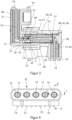
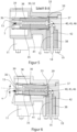
- Figur 5:
- eine Schnittdarstellung des ersten Steckverbinders gemäß der Schnittlinie A-A gemäß
Figur 4 mit einem einstückigen Leiter, der einen ersten Schenkel und einen zweiten Schenkel umfasst, wobei zwischen dem ersten Schenkel und dem zweiten Schenkel ein Federbereich ausgebildet ist, - Figur 6:
- eine Schnittdarstellung des ersten Steckverbinders gemäß der Schnittlinie B-B gemäß
Figur 4 , wobei der erste Schenkel zur Kompensation eines Achsversatzes um eine Achse senkrecht zur Steckrichtung verschwenkt ist, und - Figur 7:
- eine Schnittdarstellung des ersten Steckverbinders gemäß der Schnittlinie C-C gemäß
Figur 4 .
- Figure 1:
- a perspective view of the first connector of the connector according to the invention,
- Figure 2:
- a perspective view of the second connector of the connector according to the invention,
- Figure 3:
- according to a sectional view of the connector according to the invention with the first connector
figure 1 and according to the second connectorfigure 2 when plugged in, - Figure 4:
- a plan view of the first connector of the connector according to the invention,
- Figure 5:
- a sectional view of the first connector along the section line AA according to
figure 4 with a one-piece conductor comprising a first leg and a second leg, wherein between the first leg and the second leg a spring area is formed, - Figure 6:
- a sectional view of the first connector along the section line BB according to
figure 4 , wherein the first leg is pivoted about an axis perpendicular to the insertion direction to compensate for an axial offset, and - Figure 7:
- a sectional view of the first connector along the section line CC according to
figure 4 .
Eine erfindungsgemäße Steckverbindung 1 umfasst einen ersten Steckverbinder 10 und einen zweiten Steckverbinder 50. Der Steckverbinder 10, welcher in einer perspektivischen Ansicht in
Die Steckverbindung 1 wird beispielsweise als Antennenkontakt verwendet, der eine Vielzahl von hochfrequenten Signalen über Leiterpaare bestmöglich elektrisch und magnetisch abgeschirmt zwischen zwei Bauteilen überträgt. Im dargestellten Ausführungsbeispiel umfassen der erste Steckverbinder 10 und der zweite Steckverbinder 50 jeweils fünf Leiterpaare mit jeweils einem einstückigen Leiter 12, 52 je Steckverbinder 10, 50, wobei die Anzahl der Leiterpaare beliebig gewählt werden kann. Die Leiter 12, 52 in dem jeweiligen ersten Steckverbinder 10 und dem jeweiligen zweiten Steckverbinder 50 sind bevorzugt identisch ausgebildet.The plug-in connection 1 is used, for example, as an antenna contact, which transmits a large number of high-frequency signals via conductor pairs with the best possible electrical and magnetic shielding between two components. In the illustrated embodiment, the
Der erste Steckverbinder 10, welcher im Detail in den
Das Gehäuse 11 ist aus einem elektrisch leitfähigen Werkstoff, beispielsweise aus Aluminium, hergestellt und umfasst eine Ausnehmung 30 mit einem Steckbereich 31, in die der zweite Steckverbinder 50 bereichsweise zum Herstellen einer elektrischen Verbindung der Leiterpaare eingeführt werden kann.The
Der Leiter 12 ist elektrisch leitfähig aus einem Ganzen hergestellt und umfasst ein erstes Ende 13 und ein zweites Ende 14, wobei das erste Ende 13 eingerichtet ist, mit dem entsprechenden Leiter 52 des zweiten Steckverbinders 50 eine elektrisch leitfähige Verbindung herzustellen. Das zweite Ende 14 des Leiters 52 kann mit einem elektrischen Bauteil, beispielsweise einer (nicht dargestellten) Leiterplatte verbunden werden.The
Der jeweilige Leiter 12 kann in drei Bereiche unterteilt werden, nämlich einen ersten Schenkel 41, einen zweiten Schenkel 42 und einen Federbereich 40, wobei der Federbereich 40 zwischen dem ersten Schenkel 41 und dem zweiten Schenkel 42 angeordnet ist. Während der erste Schenkel 41 des Leiters 12 in der Steckrichtung 5 ausgerichtet ist, kann der zweite Schenkel 42 in einem Winkel, vorzugsweise wie im dargestellten Ausführungsbeispiel senkrecht zu dem ersten Schenkel 41 ausgerichtet sein. Der Federbereich 40 ist als Schwingfeder mit einer Krümmung 45 ausgebildet und kann durch Umformen, insbesondere Biegen, aus einem einstückig ausgebildeten elektrischen Leiter hergestellt sein. Der Federbereich 40 steht frei in der Ausnehmung 30 des Gehäuses 11.The
Der zweite Schenkel 42 bzw. das zweite Ende 14 des Leiters 12 ist mittels eines Dielektrikum 38 elektrisch isoliert an dem Gehäuse 11 gehalten, und steht zur Herstellung einer elektrischen Verbindung mit der nicht dargestellten Leiterplatte von dem Gehäuse 11 ab.The
Der erste Schenkel 41, siehe
Der Leiter 12 kann von einem Dielektrikum 38 und einem Außenleiter 35 umgeben sein, die zusammengefügt als ein Ganzes in die Ausnehmung 30 ragen und ausgehend von dem Federbereich 40 gemeinsam um wenigstens eine Achse senkrecht zu der Steckrichtung 5 in einen Winkel α - wie in
Die Ausnehmung 30 umfasst den Steckbereich 31 sowie einen konischen Bereich 32, der mit einem sich stetig von dem ersten Ende 13 des Leiters 12 verjüngenden Querschnitt versehen ist. Der konische Bereich 32 ist als kegelförmige Aussparung symmetrisch zu dem ersten Schenkel 41 ausgebildet. Demnach hat jeder Leiter 12 der Leiterpaare einen eigenen konischen Bereich 32 in der Ausnehmung 30.The
Der konische Bereich 32 ermöglicht ein freies Verschwenken des ersten Schenkels 41 in der Ausnehmung 30. Der konische Bereich 32 kann ebenfalls die maximale Auslenkung des ersten Schenkels 41 vorgeben und weist hierzu einen konstanten Öffnungswinkel auf. Der Öffnungswinkel des konischen Bereichs ist dabei derart gewählt, dass beim Auslenken des ersten Schenkels 41 der Federbereich 40 ausschließlich innerhalb der elastischen Materialgrenzen elastisch verformt wird, und ein vorzeitiges mechanisches Versagen des Federbereiches 40 und eine Trennung bzw. ein Brechen des elektrischen Leiters 12 verhindert ist. Bei der maximalen Auslenkung des ersten Schenkels 41, liegt bevorzugt der erste Schenkel 41 an dem konischen Bereich 32 an. Weiter bevorzugt ist der Öffnungswinkel typischerweise >0° und <60°, so dass die maximale Auslenkung zur Kompensation des Achsversatzes in jede Richtung ca. die Hälfte des Öffnungswinkels beträgt.The
Der Außenleiter 35 ist eine elektrisch leitfähige Hülse, die den ersten Schenkel 41 bzw. den Leiter 12 im Bereich des ersten Schenkels 41 umgibt und mittels des Dielektrikums 38 von diesem elektrisch getrennt mechanisch fest angeordnet ist. Der Außenleiter 35 kann bevorzugt im Querschnitt kreisrund sein. Weiterhin ist insbesondere der
Der Federkorb 39 ist näherungsweise im Querschnitt eine kreisrunde Hülse und besteht aus einer Vielzahl von abstehenden und elastischen Federzungen, die radial und axial abstehen können. Die Federzungen des Federkorbs 39 drücken an dem zweiten Ende 37 gegen die Ausnehmung 30 des Gehäuses 11 und können den Außenleiter 35 elektrisch mit dem Gehäuse 11 verbinden. Dabei ist das zweite Ende 37 des Außenleiter 35 bzw. des Federkorbs 39 derart angeordnet, dass dieser in einer gemeinsamen Ebene mit dem Federbereich 40 angeordnet ist.The
Das zweite Ende 37 des Außenleiters 35 bzw. des Federkorbs 39 ist benachbart und weiter bevorzugt in einer Achse angeordnet um die der erste Schenkel 41 durch den Federbereich 40 bei einer Auslenkung zur Kompensation des Achsversatzes in dem Winkel α verschwenkt. Darüber hinaus können die Federzungen bei einer Auslenkung des ersten Schenkels 41 eine Rückstellkraft zusätzlich zum Federbereich 40 erzeugen, wodurch der erste Schenkel 41 in die Ausgangslage zurückgestellt wird. Hierzu können die Federzungen des Federkorbes 39 an dem zweiten Ende 37 des Außenleiters 35 in eine Hinterschneidung 33 greifen, welche weiter bevorzugt als eine umfangssymmetrisch verrundete Radialnut ausgebildet ist.The
Das erste Ende 36 überragt den Leiter 12 entgegen der in
Der zweite Steckverbinder 50 wird in
Das Gehäuse 51 weist ferner für jeden Leiter 52 eine in Steckrichtung 6 abstehende Kontakthülse 65 auf, wobei die Kontakthülse 65 eingerichtet ist, in die Ausnehmung 30 des ersten Steckverbinders 10 einzugreifen. Die Kontakthülse 65 umgreift - wie
Der elektrische Leiter 52 sowie das Gehäuse 51 des zweiten Steckverbinders 50 sind bevorzugt L-förmig ausgebildet, so dass der Leiter 52 einen ersten Schenkel und einen zweiten Schenkel aufweist, welche in einem Winkel von 90° zueinander angeordnet sind. Der erste Schenkel ist in Steckrichtung 6 ausgerichtet. Der Winkel zwischen dem ersten Schenkel und dem zweiten Schenkel des Leiters 52 kann durch Umformen, beispielsweise durch Biegen, hergestellt werden.The
Weiterhin zeigt
Weiterhin ist in
Sowohl das Gehäuse 11 des ersten Steckverbinders 10 als auch das Gehäuse 51 des zweiten Steckverbinders 50 können bevorzugt gewichtsoptimiert und fertigungsoptimiert ausgebildet sein. Zur gewichtsoptimierten Herstellung des ersten Steckverbinders 10 und des zweiten Steckverbinders 50 können Aussparungen 17, 57 vorgesehen werden, durch die eine steife und verkippsichere Anordnung auf den Bauteilen und eine Gewichtsreduktion erreicht werden.Both the
Die Gehäuse 11 des ersten Steckverbinders 10 und das Gehäuse 51 des zweiten Steckverbinders 50 können bevorzugt jeweils mehrteilig ausgebildet sein und werden weiter bevorzugt aus einem Leichtmetall, bevorzugt Aluminium, in einem Spritzgussverfahren hergestellt. In einem weiteren Verfahrensschritt werden die Leiter 12, 52 mit dem Dielektrikum 38, 68 bereichsweise umhüllt, insbesondere umspritzt, und der Außenleiter 35 an dem ersten Schenkel 41 des Leiters 12 angeordnet. Anschließend werden die Leiter 12, 52 umgeformt und in eine L-förmige Form gebracht, vorzugsweise durch Biegen und anschließend in die Gehäuse 11, 51 eingesetzt. Das Einsetzen in die Gehäuse 11,51 erfolgt bevorzugt jeweils in Steckrichtung 5, 6 von der Rückseite des jeweiligen Gehäuses 11, 51 aus. Die Gehäuse 11, 51 werden beispielsweise mittels eines zweiten elektrisch leitfähigen Gehäuseteils verschlossen und können als SMD-Bauteil auf einem elektrischen Bauteil, z.B. einer Leiterplatte angebracht werden.The
- 11
- Steckverbindungconnector
- 55
- Steckrichtung von 10Insertion direction of 10
- 66
- Steckrichtung von 50Mating direction of 50
- 1010
- erster Steckverbinderfirst connector
- 1111
- GehäuseHousing
- 1212
- Leiter von 10leader of 10
- 1313
- erstes Ende von 12first end of 12
- 1414
- zweites Ende von 12second end of 12
- 1717
- Aussparungrecess
- 1919
- Befestigungsmittelfasteners
- 3030
- Ausnehmungrecess
- 3131
- Steckbereichmating area
- 3232
- konischer Bereichconical area
- 3333
- Hinterschneidungundercut
- 3535
- Außenleiterouter conductor
- 3636
- erstes Ende von 35first end of 35
- 3737
- zweites Ende von 35second end of 35
- 3838
- Dielektrikumdielectric
- 3939
- Federkorbspring basket
- 4040
- Federbereichspring range
- 4141
- erster Schenkelfirst leg
- 4242
- zweiter Schenkelsecond leg
- 4545
- Krümmungcurvature
- 4646
- Querschnittsverjüngungtaper
- 5050
- zweiter Steckverbindersecond connector
- 5151
- Gehäuse von 50housing of 50
- 5252
- Leiter von 50Head of 50
- 5353
- erstes Ende von 52first end of 52
- 5454
- zweites Ende von 52second end of 52
- 5757
- Aussparungrecess
- 5959
- Befestigungsmittelfasteners
- 6565
- Kontakthülsecontact sleeve
- 6666
- konische Öffnungconical opening
- 6868
- Dielektrikumdielectric
- 7070
- Ausnehmungrecess
Claims (13)
- Plug connector (10) comprising:- at least one housing (11) with at least one cutout (30) and- at least one single-piece conductor (12) and
an outer conductor (35),- wherein the at least one conductor (12) comprises a first limb (41) and a second limb (42),- wherein the second limb (42) of the at least one conductor (12) is partially held in the cutout (30) of the housing (11),- wherein at least one spring region (40) is arranged between the first limb (41) and the second limb (42),- wherein the first limb (41) of the at least one conductor (12) is aligned in a plug-in direction (5) and is resiliently deflectable from the spring region (40) for the compensation of an axial offset,- wherein the outer conductor (35) is at least partially arranged around the first limb (41) of the at least one conductor (12),characterized in that- the outer conductor (35) comprises, at a first end (36) and at a second end (37), a spring cage (39), and- in that the spring cage (39) at the second end (37) presses against the cutout (30) of the housing (11). - Plug connector (10) in accordance with claim 1,
characterized in that
the second limb (42) is arranged at an angle of at least 30°, preferably 90°, to the first limb (41). - Plug connector (10) in accordance with claim 1 or 2,
characterized in that
the spring region (40) allows for a pivoting movement around an axis horizontal to the plug-in direction. - Plug connector (10) in accordance with any of the preceding claims,
characterized in that
the spring region (40) comprises at least one curvature (45). - Plug connector (10) in accordance with any of the preceding claims,
characterized in that
the spring region (40) comprises a cross-sectional taper (46). - Plug connector (10) in accordance with claim 1,
characterized in that
the second end (37) of the outer conductor (35) is arranged in the plug-in direction (5) in a common plane with the spring region (40). - Plug connector (10) in accordance with any of the preceding claims,
characterized in that
a dielectric (38) is arranged between the at least one conductor (12) and the outer conductor (35). - Plug connector (10) in accordance with any of the preceding claims,
characterized in that
the first limb (41) of the at least one conductor (12) is moveably arranged in the cutout (30) in the housing, and in that the cutout (30) limits the axial offset that can be compensated. - Plug connector (10) in accordance with any of the preceding claims,
characterized in that
the cutout (30) comprises a conical region (32). - Plug connector (10) in accordance with any of the preceding claims,
characterized in that
the housing (12) is made of an electrically conductive material. - Plug connector (10) in accordance with any of the preceding claims,
characterized in that
the housing (12) comprises attachment means (19) which are implemented to be attached to a circuit board. - Plug connector (10) in accordance with any of the preceding claims,
characterized in that
the plug connector (10) is an SMD component. - Plug connection (1), comprising:- at least one first plug connector (10) in accordance with any of claims 1 to 12,- and a second plug connector (50) with at least one conductor (52) integrated in at least one housing (51)- wherein each of the first plug connector (10) and the second plug connector (50) can be transferred in a respective plug-in direction (5, 6) into a plugged-in state,- wherein the first plug connector (10) and the second plug connector (50), when in the plugged-in state of the plug connection (1), establish an electrical connection between each of the at least one conductors (12, 52), between the first plug connector (10) and the second plug connector (50), and- wherein the at least one conductor (12) of the first plug connector (12) and/or the at least one conductor (52) of the second plug connector (50) make it possible to resiliently compensate an axial offset between the respective conductors (12, 52).
Applications Claiming Priority (1)
| Application Number | Priority Date | Filing Date | Title |
|---|---|---|---|
| DE102018118405.0A DE102018118405B3 (en) | 2018-07-30 | 2018-07-30 | Connector and plug connection with such a connector |
Publications (2)
| Publication Number | Publication Date |
|---|---|
| EP3605746A1 EP3605746A1 (en) | 2020-02-05 |
| EP3605746B1 true EP3605746B1 (en) | 2023-03-15 |
Family
ID=67513333
Family Applications (1)
| Application Number | Title | Priority Date | Filing Date |
|---|---|---|---|
| EP19188732.2A Active EP3605746B1 (en) | 2018-07-30 | 2019-07-28 | Plug connector and connection with such a connector |
Country Status (3)
| Country | Link |
|---|---|
| EP (1) | EP3605746B1 (en) |
| CN (1) | CN110783783B (en) |
| DE (1) | DE102018118405B3 (en) |
Families Citing this family (2)
| Publication number | Priority date | Publication date | Assignee | Title |
|---|---|---|---|---|
| DE102020209260A1 (en) | 2020-07-22 | 2022-01-27 | Yamaichi Electronics Deutschland Gmbh | Connector, in particular a mini-coax automotive connector, for connecting to a compatible connector device, and method for manufacturing a connector |
| CN116632595A (en) * | 2022-12-24 | 2023-08-22 | 长春捷翼汽车科技股份有限公司 | Connector assembly |
Family Cites Families (20)
| Publication number | Priority date | Publication date | Assignee | Title |
|---|---|---|---|---|
| JP3016164B2 (en) * | 1991-06-19 | 2000-03-06 | 日本エー・エム・ピー株式会社 | Movable connector |
| JP2527144Y2 (en) * | 1992-11-19 | 1997-02-26 | モレックス インコーポレーテッド | Electrical connector for connecting printed circuit boards |
| NL9301779A (en) * | 1993-10-14 | 1995-05-01 | Connector Systems Tech Nv | Electrical connector for mounting on the surface of a printed circuit board. |
| US6164977A (en) * | 1998-02-09 | 2000-12-26 | Itt Manufacturing Enterprises, Inc. | Standoff board-mounted coaxial connector |
| DE10232662A1 (en) * | 2002-07-18 | 2004-01-29 | Harting Automotive Gmbh & Co. Kg | Angled coaxial connector |
| ITBO20050237A1 (en) * | 2005-04-14 | 2006-10-15 | Selta S R L | CONNECTOR CONNECTED |
| CN201112911Y (en) * | 2007-10-12 | 2008-09-10 | 富士康(昆山)电脑接插件有限公司 | Electric connector |
| EP2342781A1 (en) * | 2008-10-27 | 2011-07-13 | Fci | Connector with floating terminals |
| DE102010037498B4 (en) * | 2010-09-13 | 2013-11-07 | Hachadorian Design & Calculation Gmbh | Electric contact |
| CN201975540U (en) * | 2010-12-09 | 2011-09-14 | 中航光电科技股份有限公司 | Electrical connector used for circuit board |
| KR101301772B1 (en) * | 2012-03-06 | 2013-08-29 | 주식회사 텔콘 | Rf connector for substrates |
| US8888519B2 (en) * | 2012-05-31 | 2014-11-18 | Cinch Connectivity Solutions, Inc. | Modular RF connector system |
| EP2680371B1 (en) * | 2012-06-29 | 2018-04-11 | Corning Optical Communications RF LLC | Tubular insulator for coaxial connector |
| JP5454646B1 (en) * | 2012-09-25 | 2014-03-26 | 第一精工株式会社 | Electrical connector |
| JP6103917B2 (en) * | 2012-12-18 | 2017-03-29 | ヒロセ電機株式会社 | Electrical connector assembly |
| JP6064808B2 (en) * | 2013-06-21 | 2017-01-25 | 住友電装株式会社 | connector |
| DE202013006067U1 (en) * | 2013-07-05 | 2013-08-12 | Rosenberger Hochfrequenztechnik Gmbh & Co. Kg | Connectors |
| DE102014102555B4 (en) * | 2014-02-27 | 2016-03-03 | Wago Verwaltungsgesellschaft Mbh | Electrical device with pendulum contact |
| JP6761311B2 (en) * | 2016-09-13 | 2020-09-23 | ヒロセ電機株式会社 | Electrical connector for circuit board |
| DE102017112025B4 (en) * | 2017-06-01 | 2019-09-12 | Ims Connector Systems Gmbh | Electrical connector with tolerance compensation |
-
2018
- 2018-07-30 DE DE102018118405.0A patent/DE102018118405B3/en active Active
-
2019
- 2019-07-28 EP EP19188732.2A patent/EP3605746B1/en active Active
- 2019-07-30 CN CN201910694291.1A patent/CN110783783B/en active Active
Also Published As
| Publication number | Publication date |
|---|---|
| CN110783783B (en) | 2023-10-20 |
| CN110783783A (en) | 2020-02-11 |
| DE102018118405B3 (en) | 2019-12-05 |
| EP3605746A1 (en) | 2020-02-05 |
Similar Documents
| Publication | Publication Date | Title |
|---|---|---|
| EP3198686B1 (en) | Plug-in connector | |
| EP2834888B1 (en) | Printed circuit board coaxial connector | |
| EP3103163B1 (en) | Coaxial connector assembly | |
| DE60305146T2 (en) | Electrical connector with locking ring, in particular a coaxial connector | |
| EP3420612B1 (en) | Electrical plug connector | |
| EP2684259B1 (en) | High frequency coaxial connector | |
| EP0772261A2 (en) | Coaxial connector | |
| WO2018197641A1 (en) | Contact element for a connector | |
| DE102016006598A1 (en) | Connectors | |
| EP3593412B1 (en) | Inner conductor element and method of producing a system | |
| WO2021013297A1 (en) | Contact element for electrically connecting printed circuit boards and method for assembling a printed circuit board arrangement | |
| EP3605746B1 (en) | Plug connector and connection with such a connector | |
| DE102017115914B3 (en) | Printed circuit board connector with a screen element | |
| EP3579346B1 (en) | Electrical connector for circuit boards | |
| EP3714514B1 (en) | Plug-type connector | |
| EP3979436B1 (en) | Electrical connector, circuit board assembly and method for mounting a circuit board assembly | |
| WO2019063149A1 (en) | Spring-loaded inner-conductor contact element | |
| EP2586105B1 (en) | Plug-type connector | |
| WO2016169990A1 (en) | Plug connector system | |
| DE102016006923B4 (en) | coaxial connector | |
| EP3482461B1 (en) | Electric contact device | |
| DE102012005812A1 (en) | Electrical connector with integrated impedance matching element | |
| DE202019104312U1 (en) | Test plug for shorting a coaxial plug | |
| EP0290827A2 (en) | Electrical connector for printed circuit boards | |
| EP1727244B1 (en) | Combistrip |
Legal Events
| Date | Code | Title | Description |
|---|---|---|---|
| PUAI | Public reference made under article 153(3) epc to a published international application that has entered the european phase |
Free format text: ORIGINAL CODE: 0009012 |
|
| STAA | Information on the status of an ep patent application or granted ep patent |
Free format text: STATUS: THE APPLICATION HAS BEEN PUBLISHED |
|
| AK | Designated contracting states |
Kind code of ref document: A1 Designated state(s): AL AT BE BG CH CY CZ DE DK EE ES FI FR GB GR HR HU IE IS IT LI LT LU LV MC MK MT NL NO PL PT RO RS SE SI SK SM TR |
|
| AX | Request for extension of the european patent |
Extension state: BA ME |
|
| STAA | Information on the status of an ep patent application or granted ep patent |
Free format text: STATUS: REQUEST FOR EXAMINATION WAS MADE |
|
| 17P | Request for examination filed |
Effective date: 20200804 |
|
| RBV | Designated contracting states (corrected) |
Designated state(s): AL AT BE BG CH CY CZ DE DK EE ES FI FR GB GR HR HU IE IS IT LI LT LU LV MC MK MT NL NO PL PT RO RS SE SI SK SM TR |
|
| STAA | Information on the status of an ep patent application or granted ep patent |
Free format text: STATUS: EXAMINATION IS IN PROGRESS |
|
| 17Q | First examination report despatched |
Effective date: 20210628 |
|
| GRAP | Despatch of communication of intention to grant a patent |
Free format text: ORIGINAL CODE: EPIDOSNIGR1 |
|
| STAA | Information on the status of an ep patent application or granted ep patent |
Free format text: STATUS: GRANT OF PATENT IS INTENDED |
|
| RIC1 | Information provided on ipc code assigned before grant |
Ipc: H01R 24/38 20110101ALN20220926BHEP Ipc: H01R 12/91 20110101ALI20220926BHEP Ipc: H01R 13/631 20060101AFI20220926BHEP |
|
| INTG | Intention to grant announced |
Effective date: 20221017 |
|
| GRAS | Grant fee paid |
Free format text: ORIGINAL CODE: EPIDOSNIGR3 |
|
| GRAA | (expected) grant |
Free format text: ORIGINAL CODE: 0009210 |
|
| STAA | Information on the status of an ep patent application or granted ep patent |
Free format text: STATUS: THE PATENT HAS BEEN GRANTED |
|
| AK | Designated contracting states |
Kind code of ref document: B1 Designated state(s): AL AT BE BG CH CY CZ DE DK EE ES FI FR GB GR HR HU IE IS IT LI LT LU LV MC MK MT NL NO PL PT RO RS SE SI SK SM TR |
|
| REG | Reference to a national code |
Ref country code: CH Ref legal event code: EP Ref country code: GB Ref legal event code: FG4D Free format text: NOT ENGLISH |
|
| REG | Reference to a national code |
Ref country code: DE Ref legal event code: R096 Ref document number: 502019007198 Country of ref document: DE |
|
| REG | Reference to a national code |
Ref country code: IE Ref legal event code: FG4D Free format text: LANGUAGE OF EP DOCUMENT: GERMAN |
|
| REG | Reference to a national code |
Ref country code: AT Ref legal event code: REF Ref document number: 1554535 Country of ref document: AT Kind code of ref document: T Effective date: 20230415 |
|
| REG | Reference to a national code |
Ref country code: LT Ref legal event code: MG9D |
|
| REG | Reference to a national code |
Ref country code: NL Ref legal event code: MP Effective date: 20230315 |
|
| PG25 | Lapsed in a contracting state [announced via postgrant information from national office to epo] |
Ref country code: RS Free format text: LAPSE BECAUSE OF FAILURE TO SUBMIT A TRANSLATION OF THE DESCRIPTION OR TO PAY THE FEE WITHIN THE PRESCRIBED TIME-LIMIT Effective date: 20230315 Ref country code: NO Free format text: LAPSE BECAUSE OF FAILURE TO SUBMIT A TRANSLATION OF THE DESCRIPTION OR TO PAY THE FEE WITHIN THE PRESCRIBED TIME-LIMIT Effective date: 20230615 Ref country code: LV Free format text: LAPSE BECAUSE OF FAILURE TO SUBMIT A TRANSLATION OF THE DESCRIPTION OR TO PAY THE FEE WITHIN THE PRESCRIBED TIME-LIMIT Effective date: 20230315 Ref country code: LT Free format text: LAPSE BECAUSE OF FAILURE TO SUBMIT A TRANSLATION OF THE DESCRIPTION OR TO PAY THE FEE WITHIN THE PRESCRIBED TIME-LIMIT Effective date: 20230315 Ref country code: HR Free format text: LAPSE BECAUSE OF FAILURE TO SUBMIT A TRANSLATION OF THE DESCRIPTION OR TO PAY THE FEE WITHIN THE PRESCRIBED TIME-LIMIT Effective date: 20230315 |
|
| PG25 | Lapsed in a contracting state [announced via postgrant information from national office to epo] |
Ref country code: SE Free format text: LAPSE BECAUSE OF FAILURE TO SUBMIT A TRANSLATION OF THE DESCRIPTION OR TO PAY THE FEE WITHIN THE PRESCRIBED TIME-LIMIT Effective date: 20230315 Ref country code: NL Free format text: LAPSE BECAUSE OF FAILURE TO SUBMIT A TRANSLATION OF THE DESCRIPTION OR TO PAY THE FEE WITHIN THE PRESCRIBED TIME-LIMIT Effective date: 20230315 Ref country code: GR Free format text: LAPSE BECAUSE OF FAILURE TO SUBMIT A TRANSLATION OF THE DESCRIPTION OR TO PAY THE FEE WITHIN THE PRESCRIBED TIME-LIMIT Effective date: 20230616 Ref country code: FI Free format text: LAPSE BECAUSE OF FAILURE TO SUBMIT A TRANSLATION OF THE DESCRIPTION OR TO PAY THE FEE WITHIN THE PRESCRIBED TIME-LIMIT Effective date: 20230315 |
|
| PG25 | Lapsed in a contracting state [announced via postgrant information from national office to epo] |
Ref country code: SM Free format text: LAPSE BECAUSE OF FAILURE TO SUBMIT A TRANSLATION OF THE DESCRIPTION OR TO PAY THE FEE WITHIN THE PRESCRIBED TIME-LIMIT Effective date: 20230315 Ref country code: RO Free format text: LAPSE BECAUSE OF FAILURE TO SUBMIT A TRANSLATION OF THE DESCRIPTION OR TO PAY THE FEE WITHIN THE PRESCRIBED TIME-LIMIT Effective date: 20230315 Ref country code: PT Free format text: LAPSE BECAUSE OF FAILURE TO SUBMIT A TRANSLATION OF THE DESCRIPTION OR TO PAY THE FEE WITHIN THE PRESCRIBED TIME-LIMIT Effective date: 20230717 Ref country code: ES Free format text: LAPSE BECAUSE OF FAILURE TO SUBMIT A TRANSLATION OF THE DESCRIPTION OR TO PAY THE FEE WITHIN THE PRESCRIBED TIME-LIMIT Effective date: 20230315 Ref country code: EE Free format text: LAPSE BECAUSE OF FAILURE TO SUBMIT A TRANSLATION OF THE DESCRIPTION OR TO PAY THE FEE WITHIN THE PRESCRIBED TIME-LIMIT Effective date: 20230315 Ref country code: CZ Free format text: LAPSE BECAUSE OF FAILURE TO SUBMIT A TRANSLATION OF THE DESCRIPTION OR TO PAY THE FEE WITHIN THE PRESCRIBED TIME-LIMIT Effective date: 20230315 |
|
| PG25 | Lapsed in a contracting state [announced via postgrant information from national office to epo] |
Ref country code: SK Free format text: LAPSE BECAUSE OF FAILURE TO SUBMIT A TRANSLATION OF THE DESCRIPTION OR TO PAY THE FEE WITHIN THE PRESCRIBED TIME-LIMIT Effective date: 20230315 Ref country code: PL Free format text: LAPSE BECAUSE OF FAILURE TO SUBMIT A TRANSLATION OF THE DESCRIPTION OR TO PAY THE FEE WITHIN THE PRESCRIBED TIME-LIMIT Effective date: 20230315 Ref country code: IS Free format text: LAPSE BECAUSE OF FAILURE TO SUBMIT A TRANSLATION OF THE DESCRIPTION OR TO PAY THE FEE WITHIN THE PRESCRIBED TIME-LIMIT Effective date: 20230715 |
|
| PGFP | Annual fee paid to national office [announced via postgrant information from national office to epo] |
Ref country code: FR Payment date: 20230724 Year of fee payment: 5 Ref country code: DE Payment date: 20230824 Year of fee payment: 5 |
|
| REG | Reference to a national code |
Ref country code: DE Ref legal event code: R097 Ref document number: 502019007198 Country of ref document: DE |
|
| PLBE | No opposition filed within time limit |
Free format text: ORIGINAL CODE: 0009261 |
|
| STAA | Information on the status of an ep patent application or granted ep patent |
Free format text: STATUS: NO OPPOSITION FILED WITHIN TIME LIMIT |
|
| PG25 | Lapsed in a contracting state [announced via postgrant information from national office to epo] |
Ref country code: SI Free format text: LAPSE BECAUSE OF FAILURE TO SUBMIT A TRANSLATION OF THE DESCRIPTION OR TO PAY THE FEE WITHIN THE PRESCRIBED TIME-LIMIT Effective date: 20230315 Ref country code: DK Free format text: LAPSE BECAUSE OF FAILURE TO SUBMIT A TRANSLATION OF THE DESCRIPTION OR TO PAY THE FEE WITHIN THE PRESCRIBED TIME-LIMIT Effective date: 20230315 |
|
| 26N | No opposition filed |
Effective date: 20231218 |
|
| PG25 | Lapsed in a contracting state [announced via postgrant information from national office to epo] |
Ref country code: MC Free format text: LAPSE BECAUSE OF FAILURE TO SUBMIT A TRANSLATION OF THE DESCRIPTION OR TO PAY THE FEE WITHIN THE PRESCRIBED TIME-LIMIT Effective date: 20230315 |
|
| PG25 | Lapsed in a contracting state [announced via postgrant information from national office to epo] |
Ref country code: MC Free format text: LAPSE BECAUSE OF FAILURE TO SUBMIT A TRANSLATION OF THE DESCRIPTION OR TO PAY THE FEE WITHIN THE PRESCRIBED TIME-LIMIT Effective date: 20230315 |
|
| REG | Reference to a national code |
Ref country code: CH Ref legal event code: PL |
|
| REG | Reference to a national code |
Ref country code: BE Ref legal event code: MM Effective date: 20230731 |
|
| PG25 | Lapsed in a contracting state [announced via postgrant information from national office to epo] |
Ref country code: LU Free format text: LAPSE BECAUSE OF NON-PAYMENT OF DUE FEES Effective date: 20230728 |
|
| GBPC | Gb: european patent ceased through non-payment of renewal fee |
Effective date: 20230728 |
|
| PG25 | Lapsed in a contracting state [announced via postgrant information from national office to epo] |
Ref country code: LU Free format text: LAPSE BECAUSE OF NON-PAYMENT OF DUE FEES Effective date: 20230728 |
|
| REG | Reference to a national code |
Ref country code: IE Ref legal event code: MM4A |
|
| PG25 | Lapsed in a contracting state [announced via postgrant information from national office to epo] |
Ref country code: CH Free format text: LAPSE BECAUSE OF NON-PAYMENT OF DUE FEES Effective date: 20230731 Ref country code: GB Free format text: LAPSE BECAUSE OF NON-PAYMENT OF DUE FEES Effective date: 20230728 |
|
| PG25 | Lapsed in a contracting state [announced via postgrant information from national office to epo] |
Ref country code: IT Free format text: LAPSE BECAUSE OF FAILURE TO SUBMIT A TRANSLATION OF THE DESCRIPTION OR TO PAY THE FEE WITHIN THE PRESCRIBED TIME-LIMIT Effective date: 20230315 Ref country code: BE Free format text: LAPSE BECAUSE OF NON-PAYMENT OF DUE FEES Effective date: 20230731 |
|
| PG25 | Lapsed in a contracting state [announced via postgrant information from national office to epo] |
Ref country code: IE Free format text: LAPSE BECAUSE OF NON-PAYMENT OF DUE FEES Effective date: 20230728 |
|
| PG25 | Lapsed in a contracting state [announced via postgrant information from national office to epo] |
Ref country code: IE Free format text: LAPSE BECAUSE OF NON-PAYMENT OF DUE FEES Effective date: 20230728 |