EP3605496A1 - Controller and control method - Google Patents
Controller and control method Download PDFInfo
- Publication number
- EP3605496A1 EP3605496A1 EP18715255.8A EP18715255A EP3605496A1 EP 3605496 A1 EP3605496 A1 EP 3605496A1 EP 18715255 A EP18715255 A EP 18715255A EP 3605496 A1 EP3605496 A1 EP 3605496A1
- Authority
- EP
- European Patent Office
- Prior art keywords
- motorcycle
- deceleration
- automatic
- automatic cruise
- lean angle
- Prior art date
- Legal status (The legal status is an assumption and is not a legal conclusion. Google has not performed a legal analysis and makes no representation as to the accuracy of the status listed.)
- Granted
Links
Images


Classifications
-
- G—PHYSICS
- G08—SIGNALLING
- G08G—TRAFFIC CONTROL SYSTEMS
- G08G1/00—Traffic control systems for road vehicles
- G08G1/16—Anti-collision systems
- G08G1/166—Anti-collision systems for active traffic, e.g. moving vehicles, pedestrians, bikes
-
- B—PERFORMING OPERATIONS; TRANSPORTING
- B60—VEHICLES IN GENERAL
- B60T—VEHICLE BRAKE CONTROL SYSTEMS OR PARTS THEREOF; BRAKE CONTROL SYSTEMS OR PARTS THEREOF, IN GENERAL; ARRANGEMENT OF BRAKING ELEMENTS ON VEHICLES IN GENERAL; PORTABLE DEVICES FOR PREVENTING UNWANTED MOVEMENT OF VEHICLES; VEHICLE MODIFICATIONS TO FACILITATE COOLING OF BRAKES
- B60T13/00—Transmitting braking action from initiating means to ultimate brake actuator with power assistance or drive; Brake systems incorporating such transmitting means, e.g. air-pressure brake systems
- B60T13/10—Transmitting braking action from initiating means to ultimate brake actuator with power assistance or drive; Brake systems incorporating such transmitting means, e.g. air-pressure brake systems with fluid assistance, drive, or release
- B60T13/12—Transmitting braking action from initiating means to ultimate brake actuator with power assistance or drive; Brake systems incorporating such transmitting means, e.g. air-pressure brake systems with fluid assistance, drive, or release the fluid being liquid
- B60T13/14—Transmitting braking action from initiating means to ultimate brake actuator with power assistance or drive; Brake systems incorporating such transmitting means, e.g. air-pressure brake systems with fluid assistance, drive, or release the fluid being liquid using accumulators or reservoirs fed by pumps
- B60T13/142—Systems with master cylinder
- B60T13/145—Master cylinder integrated or hydraulically coupled with booster
- B60T13/146—Part of the system directly actuated by booster pressure
-
- B—PERFORMING OPERATIONS; TRANSPORTING
- B60—VEHICLES IN GENERAL
- B60T—VEHICLE BRAKE CONTROL SYSTEMS OR PARTS THEREOF; BRAKE CONTROL SYSTEMS OR PARTS THEREOF, IN GENERAL; ARRANGEMENT OF BRAKING ELEMENTS ON VEHICLES IN GENERAL; PORTABLE DEVICES FOR PREVENTING UNWANTED MOVEMENT OF VEHICLES; VEHICLE MODIFICATIONS TO FACILITATE COOLING OF BRAKES
- B60T13/00—Transmitting braking action from initiating means to ultimate brake actuator with power assistance or drive; Brake systems incorporating such transmitting means, e.g. air-pressure brake systems
- B60T13/10—Transmitting braking action from initiating means to ultimate brake actuator with power assistance or drive; Brake systems incorporating such transmitting means, e.g. air-pressure brake systems with fluid assistance, drive, or release
- B60T13/66—Electrical control in fluid-pressure brake systems
- B60T13/662—Electrical control in fluid-pressure brake systems characterised by specified functions of the control system components
-
- B—PERFORMING OPERATIONS; TRANSPORTING
- B60—VEHICLES IN GENERAL
- B60T—VEHICLE BRAKE CONTROL SYSTEMS OR PARTS THEREOF; BRAKE CONTROL SYSTEMS OR PARTS THEREOF, IN GENERAL; ARRANGEMENT OF BRAKING ELEMENTS ON VEHICLES IN GENERAL; PORTABLE DEVICES FOR PREVENTING UNWANTED MOVEMENT OF VEHICLES; VEHICLE MODIFICATIONS TO FACILITATE COOLING OF BRAKES
- B60T13/00—Transmitting braking action from initiating means to ultimate brake actuator with power assistance or drive; Brake systems incorporating such transmitting means, e.g. air-pressure brake systems
- B60T13/10—Transmitting braking action from initiating means to ultimate brake actuator with power assistance or drive; Brake systems incorporating such transmitting means, e.g. air-pressure brake systems with fluid assistance, drive, or release
- B60T13/66—Electrical control in fluid-pressure brake systems
- B60T13/68—Electrical control in fluid-pressure brake systems by electrically-controlled valves
- B60T13/686—Electrical control in fluid-pressure brake systems by electrically-controlled valves in hydraulic systems or parts thereof
-
- B—PERFORMING OPERATIONS; TRANSPORTING
- B60—VEHICLES IN GENERAL
- B60T—VEHICLE BRAKE CONTROL SYSTEMS OR PARTS THEREOF; BRAKE CONTROL SYSTEMS OR PARTS THEREOF, IN GENERAL; ARRANGEMENT OF BRAKING ELEMENTS ON VEHICLES IN GENERAL; PORTABLE DEVICES FOR PREVENTING UNWANTED MOVEMENT OF VEHICLES; VEHICLE MODIFICATIONS TO FACILITATE COOLING OF BRAKES
- B60T7/00—Brake-action initiating means
- B60T7/12—Brake-action initiating means for automatic initiation; for initiation not subject to will of driver or passenger
- B60T7/22—Brake-action initiating means for automatic initiation; for initiation not subject to will of driver or passenger initiated by contact of vehicle, e.g. bumper, with an external object, e.g. another vehicle, or by means of contactless obstacle detectors mounted on the vehicle
-
- B—PERFORMING OPERATIONS; TRANSPORTING
- B60—VEHICLES IN GENERAL
- B60T—VEHICLE BRAKE CONTROL SYSTEMS OR PARTS THEREOF; BRAKE CONTROL SYSTEMS OR PARTS THEREOF, IN GENERAL; ARRANGEMENT OF BRAKING ELEMENTS ON VEHICLES IN GENERAL; PORTABLE DEVICES FOR PREVENTING UNWANTED MOVEMENT OF VEHICLES; VEHICLE MODIFICATIONS TO FACILITATE COOLING OF BRAKES
- B60T8/00—Arrangements for adjusting wheel-braking force to meet varying vehicular or ground-surface conditions, e.g. limiting or varying distribution of braking force
- B60T8/17—Using electrical or electronic regulation means to control braking
- B60T8/1701—Braking or traction control means specially adapted for particular types of vehicles
- B60T8/1706—Braking or traction control means specially adapted for particular types of vehicles for single-track vehicles, e.g. motorcycles
-
- B—PERFORMING OPERATIONS; TRANSPORTING
- B60—VEHICLES IN GENERAL
- B60T—VEHICLE BRAKE CONTROL SYSTEMS OR PARTS THEREOF; BRAKE CONTROL SYSTEMS OR PARTS THEREOF, IN GENERAL; ARRANGEMENT OF BRAKING ELEMENTS ON VEHICLES IN GENERAL; PORTABLE DEVICES FOR PREVENTING UNWANTED MOVEMENT OF VEHICLES; VEHICLE MODIFICATIONS TO FACILITATE COOLING OF BRAKES
- B60T8/00—Arrangements for adjusting wheel-braking force to meet varying vehicular or ground-surface conditions, e.g. limiting or varying distribution of braking force
- B60T8/17—Using electrical or electronic regulation means to control braking
- B60T8/1755—Brake regulation specially adapted to control the stability of the vehicle, e.g. taking into account yaw rate or transverse acceleration in a curve
- B60T8/17554—Brake regulation specially adapted to control the stability of the vehicle, e.g. taking into account yaw rate or transverse acceleration in a curve specially adapted for enhancing stability around the vehicles longitudinal axle, i.e. roll-over prevention
-
- B—PERFORMING OPERATIONS; TRANSPORTING
- B60—VEHICLES IN GENERAL
- B60T—VEHICLE BRAKE CONTROL SYSTEMS OR PARTS THEREOF; BRAKE CONTROL SYSTEMS OR PARTS THEREOF, IN GENERAL; ARRANGEMENT OF BRAKING ELEMENTS ON VEHICLES IN GENERAL; PORTABLE DEVICES FOR PREVENTING UNWANTED MOVEMENT OF VEHICLES; VEHICLE MODIFICATIONS TO FACILITATE COOLING OF BRAKES
- B60T8/00—Arrangements for adjusting wheel-braking force to meet varying vehicular or ground-surface conditions, e.g. limiting or varying distribution of braking force
- B60T8/17—Using electrical or electronic regulation means to control braking
- B60T8/1755—Brake regulation specially adapted to control the stability of the vehicle, e.g. taking into account yaw rate or transverse acceleration in a curve
- B60T8/17558—Brake regulation specially adapted to control the stability of the vehicle, e.g. taking into account yaw rate or transverse acceleration in a curve specially adapted for collision avoidance or collision mitigation
-
- B—PERFORMING OPERATIONS; TRANSPORTING
- B60—VEHICLES IN GENERAL
- B60T—VEHICLE BRAKE CONTROL SYSTEMS OR PARTS THEREOF; BRAKE CONTROL SYSTEMS OR PARTS THEREOF, IN GENERAL; ARRANGEMENT OF BRAKING ELEMENTS ON VEHICLES IN GENERAL; PORTABLE DEVICES FOR PREVENTING UNWANTED MOVEMENT OF VEHICLES; VEHICLE MODIFICATIONS TO FACILITATE COOLING OF BRAKES
- B60T8/00—Arrangements for adjusting wheel-braking force to meet varying vehicular or ground-surface conditions, e.g. limiting or varying distribution of braking force
- B60T8/17—Using electrical or electronic regulation means to control braking
- B60T8/176—Brake regulation specially adapted to prevent excessive wheel slip during vehicle deceleration, e.g. ABS
- B60T8/1763—Brake regulation specially adapted to prevent excessive wheel slip during vehicle deceleration, e.g. ABS responsive to the coefficient of friction between the wheels and the ground surface
- B60T8/17636—Microprocessor-based systems
-
- B—PERFORMING OPERATIONS; TRANSPORTING
- B60—VEHICLES IN GENERAL
- B60T—VEHICLE BRAKE CONTROL SYSTEMS OR PARTS THEREOF; BRAKE CONTROL SYSTEMS OR PARTS THEREOF, IN GENERAL; ARRANGEMENT OF BRAKING ELEMENTS ON VEHICLES IN GENERAL; PORTABLE DEVICES FOR PREVENTING UNWANTED MOVEMENT OF VEHICLES; VEHICLE MODIFICATIONS TO FACILITATE COOLING OF BRAKES
- B60T8/00—Arrangements for adjusting wheel-braking force to meet varying vehicular or ground-surface conditions, e.g. limiting or varying distribution of braking force
- B60T8/26—Arrangements for adjusting wheel-braking force to meet varying vehicular or ground-surface conditions, e.g. limiting or varying distribution of braking force characterised by producing differential braking between front and rear wheels
- B60T8/261—Arrangements for adjusting wheel-braking force to meet varying vehicular or ground-surface conditions, e.g. limiting or varying distribution of braking force characterised by producing differential braking between front and rear wheels specially adapted for use in motorcycles
-
- B—PERFORMING OPERATIONS; TRANSPORTING
- B60—VEHICLES IN GENERAL
- B60T—VEHICLE BRAKE CONTROL SYSTEMS OR PARTS THEREOF; BRAKE CONTROL SYSTEMS OR PARTS THEREOF, IN GENERAL; ARRANGEMENT OF BRAKING ELEMENTS ON VEHICLES IN GENERAL; PORTABLE DEVICES FOR PREVENTING UNWANTED MOVEMENT OF VEHICLES; VEHICLE MODIFICATIONS TO FACILITATE COOLING OF BRAKES
- B60T8/00—Arrangements for adjusting wheel-braking force to meet varying vehicular or ground-surface conditions, e.g. limiting or varying distribution of braking force
- B60T8/32—Arrangements for adjusting wheel-braking force to meet varying vehicular or ground-surface conditions, e.g. limiting or varying distribution of braking force responsive to a speed condition, e.g. acceleration or deceleration
- B60T8/321—Arrangements for adjusting wheel-braking force to meet varying vehicular or ground-surface conditions, e.g. limiting or varying distribution of braking force responsive to a speed condition, e.g. acceleration or deceleration deceleration
- B60T8/3225—Systems specially adapted for single-track vehicles, e.g. motorcycles
-
- B—PERFORMING OPERATIONS; TRANSPORTING
- B60—VEHICLES IN GENERAL
- B60W—CONJOINT CONTROL OF VEHICLE SUB-UNITS OF DIFFERENT TYPE OR DIFFERENT FUNCTION; CONTROL SYSTEMS SPECIALLY ADAPTED FOR HYBRID VEHICLES; ROAD VEHICLE DRIVE CONTROL SYSTEMS FOR PURPOSES NOT RELATED TO THE CONTROL OF A PARTICULAR SUB-UNIT
- B60W10/00—Conjoint control of vehicle sub-units of different type or different function
- B60W10/04—Conjoint control of vehicle sub-units of different type or different function including control of propulsion units
- B60W10/06—Conjoint control of vehicle sub-units of different type or different function including control of propulsion units including control of combustion engines
-
- B—PERFORMING OPERATIONS; TRANSPORTING
- B60—VEHICLES IN GENERAL
- B60W—CONJOINT CONTROL OF VEHICLE SUB-UNITS OF DIFFERENT TYPE OR DIFFERENT FUNCTION; CONTROL SYSTEMS SPECIALLY ADAPTED FOR HYBRID VEHICLES; ROAD VEHICLE DRIVE CONTROL SYSTEMS FOR PURPOSES NOT RELATED TO THE CONTROL OF A PARTICULAR SUB-UNIT
- B60W10/00—Conjoint control of vehicle sub-units of different type or different function
- B60W10/18—Conjoint control of vehicle sub-units of different type or different function including control of braking systems
- B60W10/184—Conjoint control of vehicle sub-units of different type or different function including control of braking systems with wheel brakes
-
- B—PERFORMING OPERATIONS; TRANSPORTING
- B60—VEHICLES IN GENERAL
- B60W—CONJOINT CONTROL OF VEHICLE SUB-UNITS OF DIFFERENT TYPE OR DIFFERENT FUNCTION; CONTROL SYSTEMS SPECIALLY ADAPTED FOR HYBRID VEHICLES; ROAD VEHICLE DRIVE CONTROL SYSTEMS FOR PURPOSES NOT RELATED TO THE CONTROL OF A PARTICULAR SUB-UNIT
- B60W30/00—Purposes of road vehicle drive control systems not related to the control of a particular sub-unit, e.g. of systems using conjoint control of vehicle sub-units
- B60W30/02—Control of vehicle driving stability
- B60W30/045—Improving turning performance
-
- B—PERFORMING OPERATIONS; TRANSPORTING
- B60—VEHICLES IN GENERAL
- B60W—CONJOINT CONTROL OF VEHICLE SUB-UNITS OF DIFFERENT TYPE OR DIFFERENT FUNCTION; CONTROL SYSTEMS SPECIALLY ADAPTED FOR HYBRID VEHICLES; ROAD VEHICLE DRIVE CONTROL SYSTEMS FOR PURPOSES NOT RELATED TO THE CONTROL OF A PARTICULAR SUB-UNIT
- B60W30/00—Purposes of road vehicle drive control systems not related to the control of a particular sub-unit, e.g. of systems using conjoint control of vehicle sub-units
- B60W30/14—Adaptive cruise control
- B60W30/16—Control of distance between vehicles, e.g. keeping a distance to preceding vehicle
-
- B—PERFORMING OPERATIONS; TRANSPORTING
- B62—LAND VEHICLES FOR TRAVELLING OTHERWISE THAN ON RAILS
- B62J—CYCLE SADDLES OR SEATS; AUXILIARY DEVICES OR ACCESSORIES SPECIALLY ADAPTED TO CYCLES AND NOT OTHERWISE PROVIDED FOR, e.g. ARTICLE CARRIERS OR CYCLE PROTECTORS
- B62J27/00—Safety equipment
-
- B—PERFORMING OPERATIONS; TRANSPORTING
- B62—LAND VEHICLES FOR TRAVELLING OTHERWISE THAN ON RAILS
- B62J—CYCLE SADDLES OR SEATS; AUXILIARY DEVICES OR ACCESSORIES SPECIALLY ADAPTED TO CYCLES AND NOT OTHERWISE PROVIDED FOR, e.g. ARTICLE CARRIERS OR CYCLE PROTECTORS
- B62J45/00—Electrical equipment arrangements specially adapted for use as accessories on cycles, not otherwise provided for
- B62J45/20—Cycle computers as cycle accessories
-
- B—PERFORMING OPERATIONS; TRANSPORTING
- B62—LAND VEHICLES FOR TRAVELLING OTHERWISE THAN ON RAILS
- B62J—CYCLE SADDLES OR SEATS; AUXILIARY DEVICES OR ACCESSORIES SPECIALLY ADAPTED TO CYCLES AND NOT OTHERWISE PROVIDED FOR, e.g. ARTICLE CARRIERS OR CYCLE PROTECTORS
- B62J45/00—Electrical equipment arrangements specially adapted for use as accessories on cycles, not otherwise provided for
- B62J45/40—Sensor arrangements; Mounting thereof
- B62J45/41—Sensor arrangements; Mounting thereof characterised by the type of sensor
- B62J45/415—Inclination sensors
- B62J45/4151—Inclination sensors for sensing lateral inclination of the cycle
-
- B—PERFORMING OPERATIONS; TRANSPORTING
- B62—LAND VEHICLES FOR TRAVELLING OTHERWISE THAN ON RAILS
- B62K—CYCLES; CYCLE FRAMES; CYCLE STEERING DEVICES; RIDER-OPERATED TERMINAL CONTROLS SPECIALLY ADAPTED FOR CYCLES; CYCLE AXLE SUSPENSIONS; CYCLE SIDECARS, FORECARS, OR THE LIKE
- B62K11/00—Motorcycles, engine-assisted cycles or motor scooters with one or two wheels
- B62K11/02—Frames
- B62K11/04—Frames characterised by the engine being between front and rear wheels
-
- B—PERFORMING OPERATIONS; TRANSPORTING
- B60—VEHICLES IN GENERAL
- B60W—CONJOINT CONTROL OF VEHICLE SUB-UNITS OF DIFFERENT TYPE OR DIFFERENT FUNCTION; CONTROL SYSTEMS SPECIALLY ADAPTED FOR HYBRID VEHICLES; ROAD VEHICLE DRIVE CONTROL SYSTEMS FOR PURPOSES NOT RELATED TO THE CONTROL OF A PARTICULAR SUB-UNIT
- B60W30/00—Purposes of road vehicle drive control systems not related to the control of a particular sub-unit, e.g. of systems using conjoint control of vehicle sub-units
- B60W30/02—Control of vehicle driving stability
- B60W30/04—Control of vehicle driving stability related to roll-over prevention
- B60W2030/043—Control of vehicle driving stability related to roll-over prevention about the roll axis
-
- B—PERFORMING OPERATIONS; TRANSPORTING
- B60—VEHICLES IN GENERAL
- B60W—CONJOINT CONTROL OF VEHICLE SUB-UNITS OF DIFFERENT TYPE OR DIFFERENT FUNCTION; CONTROL SYSTEMS SPECIALLY ADAPTED FOR HYBRID VEHICLES; ROAD VEHICLE DRIVE CONTROL SYSTEMS FOR PURPOSES NOT RELATED TO THE CONTROL OF A PARTICULAR SUB-UNIT
- B60W2300/00—Indexing codes relating to the type of vehicle
- B60W2300/36—Cycles; Motorcycles; Scooters
-
- B—PERFORMING OPERATIONS; TRANSPORTING
- B60—VEHICLES IN GENERAL
- B60W—CONJOINT CONTROL OF VEHICLE SUB-UNITS OF DIFFERENT TYPE OR DIFFERENT FUNCTION; CONTROL SYSTEMS SPECIALLY ADAPTED FOR HYBRID VEHICLES; ROAD VEHICLE DRIVE CONTROL SYSTEMS FOR PURPOSES NOT RELATED TO THE CONTROL OF A PARTICULAR SUB-UNIT
- B60W2520/00—Input parameters relating to overall vehicle dynamics
- B60W2520/10—Longitudinal speed
-
- B—PERFORMING OPERATIONS; TRANSPORTING
- B60—VEHICLES IN GENERAL
- B60W—CONJOINT CONTROL OF VEHICLE SUB-UNITS OF DIFFERENT TYPE OR DIFFERENT FUNCTION; CONTROL SYSTEMS SPECIALLY ADAPTED FOR HYBRID VEHICLES; ROAD VEHICLE DRIVE CONTROL SYSTEMS FOR PURPOSES NOT RELATED TO THE CONTROL OF A PARTICULAR SUB-UNIT
- B60W2520/00—Input parameters relating to overall vehicle dynamics
- B60W2520/12—Lateral speed
-
- B—PERFORMING OPERATIONS; TRANSPORTING
- B60—VEHICLES IN GENERAL
- B60W—CONJOINT CONTROL OF VEHICLE SUB-UNITS OF DIFFERENT TYPE OR DIFFERENT FUNCTION; CONTROL SYSTEMS SPECIALLY ADAPTED FOR HYBRID VEHICLES; ROAD VEHICLE DRIVE CONTROL SYSTEMS FOR PURPOSES NOT RELATED TO THE CONTROL OF A PARTICULAR SUB-UNIT
- B60W2520/00—Input parameters relating to overall vehicle dynamics
- B60W2520/18—Roll
-
- B—PERFORMING OPERATIONS; TRANSPORTING
- B60—VEHICLES IN GENERAL
- B60W—CONJOINT CONTROL OF VEHICLE SUB-UNITS OF DIFFERENT TYPE OR DIFFERENT FUNCTION; CONTROL SYSTEMS SPECIALLY ADAPTED FOR HYBRID VEHICLES; ROAD VEHICLE DRIVE CONTROL SYSTEMS FOR PURPOSES NOT RELATED TO THE CONTROL OF A PARTICULAR SUB-UNIT
- B60W2554/00—Input parameters relating to objects
- B60W2554/80—Spatial relation or speed relative to objects
- B60W2554/802—Longitudinal distance
-
- B—PERFORMING OPERATIONS; TRANSPORTING
- B60—VEHICLES IN GENERAL
- B60W—CONJOINT CONTROL OF VEHICLE SUB-UNITS OF DIFFERENT TYPE OR DIFFERENT FUNCTION; CONTROL SYSTEMS SPECIALLY ADAPTED FOR HYBRID VEHICLES; ROAD VEHICLE DRIVE CONTROL SYSTEMS FOR PURPOSES NOT RELATED TO THE CONTROL OF A PARTICULAR SUB-UNIT
- B60W2710/00—Output or target parameters relating to a particular sub-units
- B60W2710/06—Combustion engines, Gas turbines
-
- B—PERFORMING OPERATIONS; TRANSPORTING
- B60—VEHICLES IN GENERAL
- B60W—CONJOINT CONTROL OF VEHICLE SUB-UNITS OF DIFFERENT TYPE OR DIFFERENT FUNCTION; CONTROL SYSTEMS SPECIALLY ADAPTED FOR HYBRID VEHICLES; ROAD VEHICLE DRIVE CONTROL SYSTEMS FOR PURPOSES NOT RELATED TO THE CONTROL OF A PARTICULAR SUB-UNIT
- B60W2710/00—Output or target parameters relating to a particular sub-units
- B60W2710/18—Braking system
-
- B—PERFORMING OPERATIONS; TRANSPORTING
- B60—VEHICLES IN GENERAL
- B60W—CONJOINT CONTROL OF VEHICLE SUB-UNITS OF DIFFERENT TYPE OR DIFFERENT FUNCTION; CONTROL SYSTEMS SPECIALLY ADAPTED FOR HYBRID VEHICLES; ROAD VEHICLE DRIVE CONTROL SYSTEMS FOR PURPOSES NOT RELATED TO THE CONTROL OF A PARTICULAR SUB-UNIT
- B60W2720/00—Output or target parameters relating to overall vehicle dynamics
- B60W2720/18—Roll
-
- B—PERFORMING OPERATIONS; TRANSPORTING
- B60—VEHICLES IN GENERAL
- B60Y—INDEXING SCHEME RELATING TO ASPECTS CROSS-CUTTING VEHICLE TECHNOLOGY
- B60Y2200/00—Type of vehicle
- B60Y2200/10—Road Vehicles
- B60Y2200/12—Motorcycles, Trikes; Quads; Scooters
Definitions
- the present disclosure relates to a controller and a control method capable of appropriately assisting with an operation by a driver while preventing a motorcycle from falling over.
- a driver assistance system is disclosed in PTL 1. Based on information detected by a sensor that detects presence of an obstacle in a travel direction or substantially in the travel direction, the driver assistance system warns a driver of the motorcycle that the motorcycle inappropriately approaches the obstacle.
- the automatic cruise travel mode is a travel mode in which the motorcycle continues traveling with behavior thereof being at least partially controlled automatically.
- the motorcycle is controlled that a distance therefrom to a preceding vehicle approximates a distance reference value.
- the motorcycle is possibly controlled to perform an automatic cruise deceleration operation in which the motorcycle decelerates regardless of presence or absence of the operation by the driver in the automatic cruise travel mode.
- the motorcycle tends to have unstable posture when compared to a four-wheeled vehicle, for example. This leads to such a problem that the motorcycle possibly falls over due to deceleration by the automatic cruise deceleration operation.
- the invention has been made with the above-described problem as the background and therefore obtains a controller and a control method capable of appropriately assisting with an operation by a driver while preventing a motorcycle from falling over.
- a controller controls behavior of a motorcycle and includes: an acquisition section that acquires a lean angle of the motorcycle; and an execution section that initiates a control mode to make the motorcycle perform an automatic cruise deceleration operation.
- the control mode automatic deceleration that is deceleration of the motorcycle generated by the automatic cruise deceleration operation is controlled in accordance with the lean angle.
- a control method controls behavior of a motorcycle and includes: an execution step of initiating a control mode to make the motorcycle perform an automatic cruise deceleration operation; and an acquisition step of acquiring a lean angle of the motorcycle.
- automatic deceleration that is deceleration of the motorcycle generated by the automatic cruise deceleration operation is controlled in accordance with the lean angle.
- the automatic deceleration that is the deceleration of the motorcycle generated by the automatic cruise deceleration operation is controlled in accordance with the lean angle of the motorcycle. In this way, the automatic deceleration can appropriately be controlled in accordance with posture of the motorcycle. Therefore, an operation by a driver can appropriately be assisted while falling of the motorcycle is prevented.
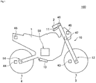
- Fig. 1 is a schematic view of an exemplary configuration of a motorcycle 100 on which a brake system 10 according to the embodiment of the invention is mounted.
- Fig. 2 is a schematic view of an exemplary configuration of the brake system 10 according to the embodiment of the invention.
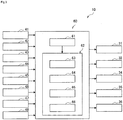
- Fig. 3 is a block diagram of an exemplary functional configuration of a controller 60 according to the embodiment of the invention.
- Fig. 4 is a view illustrating a lean angle.
- the brake system 10 is mounted on the motorcycle 100.
- the motorcycle 100 includes: a trunk 1; a handlebar 2 that is held by the trunk 1 in a freely turnable manner; a front wheel 3 that is held by the trunk 1 in the freely turnable manner with the handlebar 2; and a rear wheel 4 that is held by the trunk 1 in a freely rotatable manner.
- the brake system 10 includes: a first brake operation section 11; a front-wheel brake mechanism 12 that brakes the front wheel 3 in an interlocking manner with at least the first brake operation section 11; a second brake operation section 13; and a rear-wheel brake mechanism 14 that brakes the rear wheel 4 in the interlocking manner with at least the second brake operation section 13.
- the first brake operation section 11 is provided on the handlebar 2 and is operated by a driver's hand.
- the first brake operation section 11 is a brake lever, for example.
- the second brake operation section 13 is provided in a lower portion of the trunk 1 and is operated by the driver's foot.
- the second brake operation section 13 is a brake pedal, for example.
- Each of the front-wheel brake mechanism 12 and the rear-wheel brake mechanism 14 includes: a master cylinder 21 in which a piston (not depicted) is installed; a reservoir 22 that is attached to the master cylinder 21; a brake caliper 23 that is held by the trunk 1 and has a brake pad (not depicted) ; a wheel cylinder 24 that is provided in the brake caliper 23; a primary channel 25 through which brake fluid in the master cylinder 21 is delivered to the wheel cylinder 24; a secondary channel 26 through which the brake fluid in the wheel cylinder 24 is released; and a supply channel 27 through which the brake fluid in the master cylinder 21 is supplied to the secondary channel 26.
- An inlet valve (EV) 31 is provided in the primary channel 25.
- the secondary channel 26 bypasses a portion of the primary channel 25 between the wheel cylinder 24 side and the master cylinder 21 side from the inlet valve 31.
- the secondary channel 26 is sequentially provided with an outlet valve (AV) 32, an accumulator 33, and a pump 34 from an upstream side.
- a first valve (USV) 35 is provided in a portion of the primary channel 25 that is between an end of the primary channel 25 on the master cylinder 21 side and a portion of the primary channel 25 to which a downstream end of the secondary channel 26 is connected.
- the supply channel 27 communicates between the master cylinder 21 and a suction side of the pump 34 in the secondary channel 26.
- a second valve (HSV) 36 is provided in the supply channel 27.
- the inlet valve 31 is an electromagnetic valve that is opened in an unenergized state and closed in an energized state, for example.
- the outlet valve 32 is an electromagnetic valve that is closed in the unenergized state and opened in the energized state, for example.
- the first valve 35 is an electromagnetic valve that is opened in the unenergized state and is closed in the energized state, for example.
- the second valve 36 is an electromagnetic valve that is closed in the unenergized state and is opened in the energized state, for example.
- a hydraulic pressure control unit 50 is configured by including: members such as the inlet valves 31, the outlet valves 32, the accumulators 33, the pumps 34, the first valves 35, and the second valves 36; a base body 51 that is provided with those members and is formed with channels constituting the primary channels 25, the secondary channels 26, and the supply channels 27 therein; and the controller (ECU) 60.
- the hydraulic pressure control unit 50 is a unit that has a function of controlling a hydraulic pressure of the brake fluid in each of the wheel cylinders 24, that is, a braking force to be applied to the front wheel 3 by the front-wheel brake mechanism 12 and a braking force to be applied to the rear wheel 4 by the rear-wheel brake mechanism 14.
- the members may collectively be provided in the single base body 51 or may separately be provided in the multiple base bodies 51.
- the controller 60 may be provided as one unit or may be divided into multiple units.
- the controller 60 may be attached to the base body 51 or may be attached to a member other than the base body 51.
- the controller 60 may partially or entirely be constructed of a microcomputer, a microprocessor unit, or the like, may be constructed of a member in which firmware and the like can be updated, or may be a program module or the like that is executed by a command from a CPU or the like, for example.
- the controller 60 In a normal state, that is, in a state where an automatic cruise deceleration operation, which will be described below, is not performed, the controller 60 opens the inlet valves 31, closes the outlet valves 32, opens the first valves 35, and closes the second valves 36.
- the first brake operation section 11 is operated in such a state, in the front-wheel brake mechanism 12, the piston (not depicted) in the master cylinder 21 is pressed to increase the hydraulic pressure of the brake fluid in the wheel cylinder 24, the brake pad (not depicted) of the brake caliper 23 is then pressed against a rotor 3a of the front wheel 3, and the braking force is thereby applied to the front wheel 3.
- the piston (not depicted) in the master cylinder 21 is pressed to increase the hydraulic pressure of the brake fluid in the wheel cylinder 24, the brake pad (not depicted) of the brake caliper 23 is then pressed against a rotor 4a of the rear wheel 4, and the braking force is thereby applied to the rear wheel 4.
- the brake system 10 includes master-cylinder pressure sensors 41, wheel-cylinder pressure sensors 42, a front-wheel rotational frequency sensor 43, a rear-wheel rotational frequency sensor 44, a lean angle sensor 45, a peripheral environment sensor 46, a steering angle sensor 47, and an input device 48, for example.
- Each of the sensors and the input device 48 is communicable with the controller 60.
- Each of the master-cylinder pressure sensors 41 detects a hydraulic pressure of the brake fluid in the master cylinder 21 and outputs a detection result.
- Each of the master-cylinder pressure sensors 41 may detect another physical quantity that can substantially be converted to the hydraulic pressure of the brake fluid in the master cylinder 21.
- the master-cylinder pressure sensor 41 is provided in each of the front-wheel brake mechanism 12 and the rear-wheel brake mechanism 14.
- Each of the wheel-cylinder pressure sensors 42 detects the hydraulic pressure of the brake fluid in the wheel cylinder 24 and outputs a detection result.
- Each of the wheel-cylinder pressure sensors 42 may detect another physical quantity that can substantially be converted to the hydraulic pressure of the brake fluid in the wheel cylinder 24.
- the wheel-cylinder pressure sensor 42 is provided in each of the front-wheel brake mechanism 12 and the rear-wheel brake mechanism 14.
- the front-wheel rotational frequency sensor 43 detects a rotational frequency of the front wheel 3 and outputs a detection result.
- the front-wheel rotational frequency sensor 43 may detect another physical quantity that can substantially be converted to the rotational frequency of the front wheel 3.
- the rear-wheel rotational frequency sensor 44 detects a rotational frequency of the rear wheel 4 and outputs a detection result.
- the rear-wheel rotational frequency sensor 44 may detect another physical quantity that can substantially be converted to the rotational frequency of the rear wheel 4.
- the front-wheel rotational frequency sensor 43 and the rear-wheel rotational frequency sensor 44 are respectively provided on the front wheel 3 and the rear wheel 4.
- the lean angle sensor 45 detects a lean angle of the motorcycle 100 and an angular velocity of the lean angle thereof, and outputs a detection result.
- the lean angle corresponds to a tilt angle ⁇ of the motorcycle 100 in a rolling direction with respect to an upper vertical direction depicted in Fig. 4 .
- the motorcycle 100 is tilted in the rolling direction with respect to the upper vertical direction during turning travel.
- an inertial measurement unit (IMU) that includes a three-axis gyroscope sensor and a three-directional acceleration sensor is used as the lean angle sensor 45.
- the lean angle sensor 45 may detect another physical quantity that can substantially be converted to the lean angle of the motorcycle 100 and the angular velocity of the lean angle thereof.
- the lean angle sensor 45 is provided in the trunk 1.
- the peripheral environment sensor 46 detects peripheral environment of the motorcycle 100 and outputs a detection result. For example, as the peripheral environment, the peripheral environment sensor 46 detects a distance from the motorcycle 100 to a preceding vehicle that travels ahead of the motorcycle 100. The peripheral environment sensor 46 may detect another physical quantity that can substantially be converted to the distance from the motorcycle 100 to the preceding vehicle. More specifically, a camera that captures an image in front of the motorcycle 100 or a distance measurement sensor that can detect the distance from the motorcycle 100 to the preceding vehicle is used as the peripheral environment sensor 46. The peripheral environment sensor 46 is provided in a front portion of the trunk 1.
- the steering angle sensor 47 detects a steering angle of the motorcycle 100 and an angular velocity of the steering angle thereof, and outputs a detection result.
- the steering angle sensor 47 may detect another physical quantity that can substantially be converted to the steering angle of the motorcycle 100 and the angular velocity of the steering angle thereof.
- the steering angle sensor 47 is provided on the handlebar 2.
- the input device 48 receives a travel mode selection operation by the driver and outputs information indicative of the received operation.
- the travel mode the input device 48 at least receives the selection operation in which an automatic cruise travel mode is selected.
- the automatic cruise travel mode is a travel mode in which the motorcycle 100 continues traveling with behavior thereof being at least partially controlled automatically.
- the motorcycle 100 is controlled that the distance therefrom to the preceding vehicle approximates a distance reference value.
- the distance reference value is set to such a value that the driver's safety can be secured.
- the motorcycle 100 may be controlled that a body speed thereof approximates a speed reference value.
- the speed reference value may appropriately be set by the driver.
- the body speed of the motorcycle 100 may be computed on the basis of the rotational frequencies of the front wheel 3 and the rear wheel 4.
- a lever, a button, or a touch panel may be used as the input device 48.
- the input device 48 is provided on the handlebar 2, for example.
- the controller 60 controls the behavior of the motorcycle 100.
- the controller 60 includes an acquisition section 61 and an execution section 62, for example.
- the acquisition section 61 acquires the information that is output from each of the sensors and the input device 48, and outputs the acquired information to the execution section 62.
- the execution section 62 includes a control section 63, a deceleration request determination section 64, a change rate determination section 65, and a lean angle determination section 66, for example.
- Each of the determination sections executes determination processing by using the information that is output from each of the sensors.
- the execution section 62 initiates a control mode to make the motorcycle 100 perform the automatic cruise deceleration operation in accordance with a determination result by the deceleration request determination section 64.
- control section 63 In the control mode, the control section 63 outputs a command that governs the operations of the inlet valves 31, the outlet valves 32, the pumps 34, the first valves 35, the second valves 36, and the like in accordance with the determination result by each of the determination sections, so as to control automatic deceleration that is deceleration of the motorcycle 100 generated by the automatic cruise deceleration operation.
- control section 63 controls the automatic deceleration in accordance with the lean angle of the motorcycle 100.
- control section 63 may control the automatic deceleration in accordance with a change rate of a state amount that is related to posture of the motorcycle 100 during the turning travel.
- control of the automatic deceleration includes control to permit or prohibit the automatic cruise deceleration operation in addition to the control of the automatic deceleration of the motorcycle 100 that is generated during the automatic cruise deceleration operation.
- the controller 60 includes a storage element, and the information such as the reference values used in the processing executed by the controller 60 may be stored in the storage element in advance.
- the automatic cruise travel mode includes an automatic cruise acceleration operation in which the motorcycle 100 is accelerated regardless of presence or absence of the operation by the driver.
- the automatic cruise acceleration operation is controlled by another controller that is a separate component from the controller 60 or is integrated with the controller 60, for example.
- Automatic acceleration as acceleration of the motorcycle 100 that is generated during the automatic cruise acceleration operation may be controlled when the other controller controls engine output of the motorcycle 100.
- Fig.5 is a flowchart of an example of a processing procedure that is executed by the controller 60 according to the embodiment of the invention.
- a control flow depicted in Fig. 5 is repeated while the automatic cruise travel mode is selected.
- Step S110 and step S190 in Fig. 5 respectively correspond to initiation and termination of the control flow.
- step S110 the control flow is initiated in a state where the control mode is not initiated.
- step S113 the deceleration request determination section 64 determines whether a deceleration request has been made. If it is determined that the deceleration request has been made (step S113/Yes), the processing proceeds to step S115. On the other hand, if it is determined that the deceleration request has not been made (step S113/No), step S113 is repeated. For example, in the case where the distance from the motorcycle 100 to the preceding vehicle falls below the distance reference value, the deceleration request determination section 64 determines that the deceleration request has been made.
- the deceleration request determination section 64 may determine that the deceleration request has been made when the body speed of the motorcycle 100 exceeds the speed reference value.
- the deceleration request determination section 64 compares the distance from the motorcycle 100 to the preceding vehicle with the distance reference value or compares the body speed of the motorcycle 100 with the speed reference value.
- these comparisons may be made by the other controller that differs from the controller 60.
- the other controller outputs information indicative of results of these comparisons or information that directly indicates whether the deceleration request has been made to the controller 60. In this way, the deceleration request determination section 64 can make the determination.
- step S115 the execution section 62 initiates the control mode to make the motorcycle 100 perform the automatic cruise deceleration operation.
- step S117 the acquisition section 61 acquires the change rate of the state amount that is related to the posture of the motorcycle 100 during the turning travel.
- the state amount that is related to the posture of the motorcycle 100 during the turning travel includes the lean angle, the angular velocity of the lean angle, the steering angle, or the angular velocity of the steering angle, for example.
- step S119 the change rate determination section 65 determines whether the change rate of the state amount that is related to the posture of the motorcycle 100 during the turning travel exceeds a change rate reference value. If it is determined that the change rate exceeds the change rate reference value (step S119/Yes), the processing proceeds to step S127. On the other hand, if it is determined that the change rate does not exceed the change rate reference value (step S119/No), the processing proceeds to step S121.
- the change rate reference value is set to such a value that a determination on whether the driver has his/her intention to avoid the preceding vehicle can be made.
- step S121 the acquisition section 61 acquires the lean angle of the motorcycle 100.
- step S123 the lean angle determination section 66 determines whether the lean angle of the motorcycle 100 exceeds a lean angle reference value. If it is determined that the lean angle exceeds the lean angle reference value (step S123/Yes), the processing proceeds to step S127. On the other hand, if it is determined that the lean angle does not exceed the lean angle reference value (step S123/No), the processing proceeds to step S125.
- the lean angle reference value is such a value that a determination on whether a possibility of falling of the motorcycle 100, which is resulted from generation of the deceleration of the motorcycle 100, is excessively high can be made, and is set in accordance with a friction coefficient of a travel road surface, a design specification of the motorcycle 100, or the like, for example.
- step S125 the control section 63 permits the automatic cruise deceleration operation.
- the control section 63 causes the generation of the automatic deceleration that is the deceleration irrespective of the driver's operation, and makes the motorcycle 100 perform the automatic cruise deceleration operation.
- the control section 63 causes the generation of the automatic deceleration through generation of the braking force that is applied to the wheel by at least one of the front-wheel brake mechanism 12 and the rear-wheel brake mechanism 14.
- control section 63 drives the pump 34 in a state where the inlet valve 31 is opened, the outlet valve 32 is closed, the first valve 35 is closed, and the second valve 36 is opened, so as to cause the generation of the braking force that is applied to the wheel.
- the control section 63 controls a rotational frequency of the pump 34 and thereby controls the braking force that is applied to the wheel. More specifically, the control section 63 computes reference target deceleration that is a reference value of a target value of the automatic deceleration. For example, as a difference between the distance from the motorcycle 100 to the preceding vehicle and the distance reference value is increased (in other words, as the motorcycle 100 comes closer to the preceding vehicle), the control section 63 computes a high value as the reference target deceleration.
- the control section 63 may compute a constant value as the reference target deceleration irrespective of a magnitude of the difference between the distance from the motorcycle 100 to the preceding vehicle and the distance reference value.
- the control section 63 decides target deceleration on the basis of the computed reference target deceleration. For example, the control section 63 decides a value that is acquired by multiplying the reference target deceleration by a coefficient as the target deceleration. Next, based on the target deceleration, the control section 63 decides a target hydraulic pressure that is a target value of the hydraulic pressure of the brake fluid in the wheel cylinder 24. Then, the control section 63 controls the rotational frequency of the pump 34 such that the hydraulic pressure of the brake fluid in the wheel cylinder 24 matches the target hydraulic pressure. In this way, the automatic deceleration is controlled to match the target deceleration.
- the control section 63 computes the higher value as the reference target deceleration as a difference between the body speed of the motorcycle 100 and the speed reference value is increased, for example.
- the control section 63 may compute a constant value as the reference target deceleration irrespective of a magnitude of the difference between the body speed of the motorcycle 100 and the speed reference value.
- control section 63 computes the reference target deceleration.
- the other controller that differs from the controller 60 may compute the reference target deceleration.
- the other controller outputs information indicative of the reference target deceleration to the controller 60. In this way, the control of the automatic deceleration by the control section 63 can be realized.
- the control section 63 makes the motorcycle 100 perform the automatic cruise deceleration operation in which the automatic deceleration is lower than the automatic deceleration in the automatic cruise deceleration operation that is performed when the lean angle is small. More specifically, the control section 63 decides the value that is acquired by multiplying the reference target deceleration by the coefficient as the target deceleration, and the coefficient becomes smaller as the lean angle is increased. In this way, the control section 63 controls the automatic deceleration.
- the control section 63 makes the motorcycle 100 perform the automatic cruise deceleration operation, and the automatic deceleration therein is lower than the automatic deceleration in the automatic cruise deceleration operation that is performed when the change rate is low. More specifically, the control section 63 decides the value that is acquired by multiplying the reference target deceleration by the coefficient as the target deceleration, and the coefficient becomes smaller as the change rate of the state amount that is related to the posture of the motorcycle 100 during the turning travel is increased. In this way, the control section 63 controls the automatic deceleration.
- the control section 63 may decide the target deceleration in accordance with both of the lean angle and the change rate of the state amount that is related to the posture of the motorcycle 100 during the turning travel. In such a case, the control section 63 multiplies the reference target deceleration by both of the coefficient corresponding to the lean angle and the coefficient corresponding to the change rate of the state amount, and decides the acquired value as the target deceleration, for example.
- control section 63 controls the automatic deceleration by controlling the braking force that is applied to the wheel.
- control section 63 may control the automatic deceleration by controlling the engine output of the motorcycle 100. More specifically, the control section 63 may control the automatic deceleration by using an operational effect of engine brake that is exerted when the engine output is lowered. Alternatively, the control section 63 may control the automatic deceleration by controlling both of the braking force that is applied to the wheel and the engine output.
- step S127 the control section 63 prohibits the automatic cruise deceleration operation.
- the control section 63 brings the motorcycle 100 into the normal state where the deceleration is generated in accordance with the driver's operation. More specifically, the control section 63 brings the motorcycle 100 into a state where the inlet valves 31 are opened, the outlet valves 32 are closed, the first valves 35 are opened, and the second valves 36 are closed, so as to prohibit driving of the pumps 34.
- step S131 the deceleration request determination section 64 determines whether the deceleration request has been made. If it is determined that the deceleration request has been made (step S131/Yes), the processing returns to step S117. On the other hand, if it is determined that the deceleration request has not been made (step S131/No), the processing proceeds to step S133.
- step S131 if it is determined in step S131 that the deceleration request has been made (step S131/Yes), the control mode continues, and the processing from step S117 to step S131 is repeated.
- the control section 63 appropriately switches between a state where the automatic cruise deceleration operation is permitted and a state where the automatic cruise deceleration operation is prohibited in accordance with determination results of the determination processing by the change rate determination section 65 and the lean angle determination section 66 (step S119 and step S123).
- step S119 and step S123 are No in the state where the automatic cruise deceleration operation is permitted
- the control section 63 continues the state where the automatic cruise deceleration operation is permitted.
- the control section 63 controls the automatic deceleration of the motorcycle 100, which is generated during the automatic cruise deceleration operation, in accordance with the lean angle that is acquired during the automatic cruise deceleration operation.
- the control section 63 controls the automatic deceleration of the motorcycle 100, which is generated during the automatic cruise deceleration operation, in accordance with the change rate of the state amount that is related to the posture of the motorcycle 100 during the turning travel and that is acquired during the automatic cruise deceleration operation.
- step S119 and step S123 are Yes in the state where the automatic cruise deceleration operation is permitted
- the control section 63 cancels the state where the automatic cruise deceleration operation is permitted, and prohibits the automatic cruise deceleration operation.
- the control section 63 cancels the state where the automatic cruise deceleration operation is permitted, and prohibits the automatic cruise deceleration operation.
- control section 63 cancels the state where the automatic cruise deceleration operation is permitted, and prohibits the automatic cruise deceleration operation.
- step S119 and step S123 are Yes in the state where the automatic cruise deceleration operation is prohibited
- the control section 63 continues the state where the automatic cruise deceleration operation is prohibited.
- step S119 and step S123 are No in the state where the automatic cruise deceleration operation is prohibited
- the control section 63 cancels the state where the automatic cruise deceleration operation is prohibited, and permits the automatic cruise deceleration operation.
- the determination processing in step S119 may be eliminated from the control flow depicted in Fig. 5 .
- the control section 63 cancels the state where the automatic cruise deceleration operation is prohibited, and permits the automatic cruise deceleration operation.
- step S133 the execution section 62 terminates the control mode.
- the automatic deceleration is controlled in accordance with the lean angle of the motorcycle 100 in the control mode in which the motorcycle 100 performs the automatic cruise deceleration operation. In this way, the automatic deceleration can appropriately be controlled in accordance with the posture of the motorcycle 100. Therefore, the operation by the driver can appropriately be assisted while falling of the motorcycle 100 is prevented.
- the brake system 10 performs the automatic cruise deceleration operation, and the automatic deceleration therein is lower than the automatic deceleration in the automatic cruise deceleration operation that is performed when the lean angle is small.
- grounding areas of tires of the motorcycle 100 are reduced as the lean angle is increased.
- a friction characteristic in a grounding portion of each of the tires of the motorcycle 100 possibly has such a characteristic that a friction force is less likely to be generated in an advancing direction as the lean angle is increased. Accordingly, the possibility of falling of the motorcycle 100, which is resulted from the generation of the deceleration of the motorcycle 100, tends to be increased as the lean angle is increased.
- the automatic cruise deceleration operation is performed, and the automatic deceleration therein is lower than the automatic deceleration in the automatic cruise deceleration operation that is performed when the lean angle is small. In this way, falling of the motorcycle 100 can effectively be prevented.
- the brake system 10 controls the automatic deceleration of the motorcycle 100, which is generated during the automatic cruise deceleration operation, in accordance with the lean angle that is acquired during the automatic cruise deceleration operation.
- the automatic deceleration of the motorcycle 100 which is generated during the automatic cruise deceleration operation, can appropriately be controlled in accordance with a change in the lean angle over time during the automatic cruise deceleration operation.
- the automatic deceleration can be increased along with a decrease in the lean angle that is resulted from the automatic cruise deceleration operation. Therefore, an effect of appropriately assisting with the operation by the driver can be enhanced while falling of the motorcycle 100 is prevented.
- the brake system 10 prohibits the automatic cruise deceleration operation in the case where the lean angle exceeds the lean angle reference value.
- the automatic cruise deceleration operation can be prohibited. Therefore, falling of the motorcycle 100 can effectively be prevented.
- the brake system 10 permits the automatic cruise deceleration operation in the case where the lean angle that is acquired during the prohibition of the automatic cruise deceleration operation falls below the lean angle reference value.
- the automatic cruise deceleration operation can appropriately be performed. Therefore, the effect of appropriately assisting with the operation by the driver can be enhanced.
- the brake system 10 controls the automatic deceleration in accordance with the change rate of the state amount that is related to the posture of the motorcycle 100 during the turning travel.
- the automatic deceleration can further appropriately be controlled in accordance with the posture of the motorcycle 100. Therefore, the effect of appropriately assisting with the operation by the driver can further be enhanced while falling of the motorcycle 100 is prevented.
- the brake system 10 prohibits the automatic cruise deceleration operation in the case where the change rate of the state amount that is related to the posture of the motorcycle 100 during the turning travel exceeds the change rate reference value.
- the automatic cruise deceleration operation can be prohibited.
- the generation of the automatic deceleration against the driver's intention can be prevented. Therefore, falling of the motorcycle 100 can effectively be prevented.
- the control section 63 may prohibit the automatic cruise deceleration operation in the case where an operation amount of the motorcycle 100 by the driver exceeds an operation amount reference value.
- the operation of the motorcycle 100 by the driver includes an accelerator pedal operation, a brake operation, and a clutch operation, for example.
- the operation amount reference value is set to such a value that a determination on whether the driver has operated the motorcycle 100 can be made. Accordingly, in the case where the operation amount exceeds the operation amount reference value, the automatic cruise deceleration operation is prohibited. In this way, the generation of the automatic deceleration against the operation of the motorcycle 100 by the driver can be prevented. Therefore, falling of the motorcycle 100 can effectively be prevented.
- control section 63 may reduce the operation amount reference value in comparison with the case where the change rate does not exceed the change rate reference value. In this way, in the case where it is assumed that the driver has his/her intention to avoid the preceding vehicle, sensitivity to detection of the operation of the motorcycle 100 by the driver can be improved. Therefore, the automatic cruise deceleration operation can further reliably be prohibited.
- the brake system 10 performs the automatic cruise deceleration operation, and the automatic deceleration therein is lower than the automatic deceleration in the automatic cruise deceleration operation that is performed when the change rate is low.
- the possibility of the driver having his/her intention to avoid the preceding vehicle is higher as the change rate of the state amount is increased. Accordingly, in the case where the change rate of the state amount is high, the automatic cruise deceleration operation is performed, and the automatic deceleration therein is lower than the automatic deceleration in the automatic cruise deceleration operation that is performed when the change rate is low.
- the automatic deceleration can appropriately be controlled in accordance with the possibility of driver having his/her intention to avoid the preceding vehicle. Therefore, falling of the motorcycle 100, which is resulted from the generation of the automatic deceleration against the driver's intention, can be prevented.
- the automatic deceleration of the motorcycle 100 is controlled in the brake system 10 in accordance with the change rate of the state amount that is related to the posture of the motorcycle 100 during the turning travel and that is acquired during the automatic cruise deceleration operation.
- the automatic deceleration of the motorcycle 100 which is generated during the automatic cruise deceleration operation, can appropriately be controlled in accordance with a change in the change rate of the state amount over time during the automatic cruise deceleration operation. Therefore, falling of the motorcycle 100, which is resulted from the generation of the automatic deceleration against the driver's intention, can effectively be prevented.
- the state amount that is related to the posture of the motorcycle 100 during the turning travel and that is used for the control of the automatic deceleration includes the lean angle of the motorcycle 100 or the angular velocity of the lean angle thereof.
- the automatic deceleration can be controlled by using the detection result that is output from the lean angle sensor 45.
- another sensor for example, the steering angle sensor 47
- the brake system 10 can be simplified.
- the invention is not limited to each of the embodiments. For example, all or parts of the embodiments may be combined, or only a part of each of the embodiments may be implemented. In addition, an order of the steps may be switched, for example.
Landscapes
- Engineering & Computer Science (AREA)
- Mechanical Engineering (AREA)
- Transportation (AREA)
- Chemical & Material Sciences (AREA)
- Combustion & Propulsion (AREA)
- Automation & Control Theory (AREA)
- Physics & Mathematics (AREA)
- General Physics & Mathematics (AREA)
- Microelectronics & Electronic Packaging (AREA)
- Control Of Driving Devices And Active Controlling Of Vehicle (AREA)
- Regulating Braking Force (AREA)
Abstract
Description
- The present disclosure relates to a controller and a control method capable of appropriately assisting with an operation by a driver while preventing a motorcycle from falling over.
- As a conventional technique related to a motorcycle, a technique of assisting with an operation by a driver has been available.
- For example, a driver assistance system is disclosed in
PTL 1. Based on information detected by a sensor that detects presence of an obstacle in a travel direction or substantially in the travel direction, the driver assistance system warns a driver of the motorcycle that the motorcycle inappropriately approaches the obstacle. - [PTL 1]
JP-A-2009-116882 - In order to assist with the operation by the driver, use of an automatic cruise travel mode is considered. The automatic cruise travel mode is a travel mode in which the motorcycle continues traveling with behavior thereof being at least partially controlled automatically. In the automatic cruise travel mode, for example, the motorcycle is controlled that a distance therefrom to a preceding vehicle approximates a distance reference value. For this reason, the motorcycle is possibly controlled to perform an automatic cruise deceleration operation in which the motorcycle decelerates regardless of presence or absence of the operation by the driver in the automatic cruise travel mode. Here, the motorcycle tends to have unstable posture when compared to a four-wheeled vehicle, for example. This leads to such a problem that the motorcycle possibly falls over due to deceleration by the automatic cruise deceleration operation.
- The invention has been made with the above-described problem as the background and therefore obtains a controller and a control method capable of appropriately assisting with an operation by a driver while preventing a motorcycle from falling over.
- A controller according to an aspect of the invention controls behavior of a motorcycle and includes: an acquisition section that acquires a lean angle of the motorcycle; and an execution section that initiates a control mode to make the motorcycle perform an automatic cruise deceleration operation. In the control mode, automatic deceleration that is deceleration of the motorcycle generated by the automatic cruise deceleration operation is controlled in accordance with the lean angle.
- A control method according to another aspect of the invention controls behavior of a motorcycle and includes: an execution step of initiating a control mode to make the motorcycle perform an automatic cruise deceleration operation; and an acquisition step of acquiring a lean angle of the motorcycle. In the control mode, automatic deceleration that is deceleration of the motorcycle generated by the automatic cruise deceleration operation is controlled in accordance with the lean angle.
- In the controller and the control method according to the invention, in the control mode to make the motorcycle perform the automatic cruise deceleration operation, the automatic deceleration that is the deceleration of the motorcycle generated by the automatic cruise deceleration operation is controlled in accordance with the lean angle of the motorcycle. In this way, the automatic deceleration can appropriately be controlled in accordance with posture of the motorcycle. Therefore, an operation by a driver can appropriately be assisted while falling of the motorcycle is prevented.
-
-
Fig.1 is a schematic view of an exemplary configuration of a motorcycle on which a brake system according to an embodiment of the invention is mounted. -
Fig.2 is a schematic view of an exemplary configuration of the brake system according to the embodiment of the invention. -
Fig.3 is a block diagram of an exemplary functional configuration of a controller according to the embodiment of the invention. -
Fig.4 is a view illustrating a lean angle. -
Fig.5 is a flowchart of an example of a processing procedure that is executed by the controller according to the embodiment of the invention. - A description will hereinafter be made on a controller and a control method according to the invention by using the drawings. Note that a description will hereinafter be made on a case where a motorcycle is a two-wheeled motor vehicle; however, the motorcycle may be another motorcycle such as a three-wheeled motor vehicle. In addition, a description will be made on a case where each of a front-wheel brake mechanism and a rear-wheel brake mechanism is provided in one unit; however, at least one of the front-wheel brake mechanism and the rear-wheel brake mechanism may be provided in multiple units.
- A configuration, an operation, and the like, which will be described below, constitute merely one example, and the controller and the control method according to the invention are not limited to a case with such a configuration, such an operation, and the like.
- The same or similar description will appropriately be simplified or will not be made below. In the drawings, the same or similar members or portions will not be denoted by a reference sign or will be denoted by the same reference sign. In addition, a detailed structure will appropriately be depicted in a simplified manner or will not be depicted.
- A description will be made on a configuration of a
brake system 10 according to an embodiment of the invention.Fig. 1 is a schematic view of an exemplary configuration of amotorcycle 100 on which abrake system 10 according to the embodiment of the invention is mounted.Fig. 2 is a schematic view of an exemplary configuration of thebrake system 10 according to the embodiment of the invention.Fig. 3 is a block diagram of an exemplary functional configuration of acontroller 60 according to the embodiment of the invention.Fig. 4 is a view illustrating a lean angle. - As depicted in
Fig. 1 andFig. 2 , thebrake system 10 is mounted on themotorcycle 100. Themotorcycle 100 includes: atrunk 1; ahandlebar 2 that is held by thetrunk 1 in a freely turnable manner; afront wheel 3 that is held by thetrunk 1 in the freely turnable manner with thehandlebar 2; and arear wheel 4 that is held by thetrunk 1 in a freely rotatable manner. - For example, the
brake system 10 includes: a firstbrake operation section 11; a front-wheel brake mechanism 12 that brakes thefront wheel 3 in an interlocking manner with at least the firstbrake operation section 11; a secondbrake operation section 13; and a rear-wheel brake mechanism 14 that brakes therear wheel 4 in the interlocking manner with at least the secondbrake operation section 13. - The first
brake operation section 11 is provided on thehandlebar 2 and is operated by a driver's hand. The firstbrake operation section 11 is a brake lever, for example. The secondbrake operation section 13 is provided in a lower portion of thetrunk 1 and is operated by the driver's foot. The secondbrake operation section 13 is a brake pedal, for example. - Each of the front-
wheel brake mechanism 12 and the rear-wheel brake mechanism 14 includes: amaster cylinder 21 in which a piston (not depicted) is installed; areservoir 22 that is attached to themaster cylinder 21; abrake caliper 23 that is held by thetrunk 1 and has a brake pad (not depicted) ; awheel cylinder 24 that is provided in thebrake caliper 23; aprimary channel 25 through which brake fluid in themaster cylinder 21 is delivered to thewheel cylinder 24; asecondary channel 26 through which the brake fluid in thewheel cylinder 24 is released; and asupply channel 27 through which the brake fluid in themaster cylinder 21 is supplied to thesecondary channel 26. - An inlet valve (EV) 31 is provided in the
primary channel 25. Thesecondary channel 26 bypasses a portion of theprimary channel 25 between thewheel cylinder 24 side and themaster cylinder 21 side from theinlet valve 31. Thesecondary channel 26 is sequentially provided with an outlet valve (AV) 32, anaccumulator 33, and apump 34 from an upstream side. A first valve (USV) 35 is provided in a portion of theprimary channel 25 that is between an end of theprimary channel 25 on themaster cylinder 21 side and a portion of theprimary channel 25 to which a downstream end of thesecondary channel 26 is connected. Thesupply channel 27 communicates between themaster cylinder 21 and a suction side of thepump 34 in thesecondary channel 26. A second valve (HSV) 36 is provided in thesupply channel 27. - The
inlet valve 31 is an electromagnetic valve that is opened in an unenergized state and closed in an energized state, for example. Theoutlet valve 32 is an electromagnetic valve that is closed in the unenergized state and opened in the energized state, for example. Thefirst valve 35 is an electromagnetic valve that is opened in the unenergized state and is closed in the energized state, for example. Thesecond valve 36 is an electromagnetic valve that is closed in the unenergized state and is opened in the energized state, for example. - A hydraulic
pressure control unit 50 is configured by including: members such as theinlet valves 31, theoutlet valves 32, theaccumulators 33, thepumps 34, thefirst valves 35, and thesecond valves 36; abase body 51 that is provided with those members and is formed with channels constituting theprimary channels 25, thesecondary channels 26, and thesupply channels 27 therein; and the controller (ECU) 60. In thebrake system 10, the hydraulicpressure control unit 50 is a unit that has a function of controlling a hydraulic pressure of the brake fluid in each of thewheel cylinders 24, that is, a braking force to be applied to thefront wheel 3 by the front-wheel brake mechanism 12 and a braking force to be applied to therear wheel 4 by the rear-wheel brake mechanism 14. - The members may collectively be provided in the
single base body 51 or may separately be provided in themultiple base bodies 51. In addition, thecontroller 60 may be provided as one unit or may be divided into multiple units. Furthermore, thecontroller 60 may be attached to thebase body 51 or may be attached to a member other than thebase body 51. Moreover, thecontroller 60 may partially or entirely be constructed of a microcomputer, a microprocessor unit, or the like, may be constructed of a member in which firmware and the like can be updated, or may be a program module or the like that is executed by a command from a CPU or the like, for example. - In a normal state, that is, in a state where an automatic cruise deceleration operation, which will be described below, is not performed, the
controller 60 opens theinlet valves 31, closes theoutlet valves 32, opens thefirst valves 35, and closes thesecond valves 36. When the firstbrake operation section 11 is operated in such a state, in the front-wheel brake mechanism 12, the piston (not depicted) in themaster cylinder 21 is pressed to increase the hydraulic pressure of the brake fluid in thewheel cylinder 24, the brake pad (not depicted) of thebrake caliper 23 is then pressed against arotor 3a of thefront wheel 3, and the braking force is thereby applied to thefront wheel 3. Meanwhile, when the secondbrake operation section 13 is operated, in the rear-wheel brake mechanism 14, the piston (not depicted) in themaster cylinder 21 is pressed to increase the hydraulic pressure of the brake fluid in thewheel cylinder 24, the brake pad (not depicted) of thebrake caliper 23 is then pressed against arotor 4a of therear wheel 4, and the braking force is thereby applied to therear wheel 4. - As depicted in
Fig. 2 andFig. 3 , thebrake system 10 includes master-cylinder pressure sensors 41, wheel-cylinder pressure sensors 42, a front-wheelrotational frequency sensor 43, a rear-wheelrotational frequency sensor 44, alean angle sensor 45, aperipheral environment sensor 46, asteering angle sensor 47, and aninput device 48, for example. Each of the sensors and theinput device 48 is communicable with thecontroller 60. - Each of the master-
cylinder pressure sensors 41 detects a hydraulic pressure of the brake fluid in themaster cylinder 21 and outputs a detection result. Each of the master-cylinder pressure sensors 41 may detect another physical quantity that can substantially be converted to the hydraulic pressure of the brake fluid in themaster cylinder 21. The master-cylinder pressure sensor 41 is provided in each of the front-wheel brake mechanism 12 and the rear-wheel brake mechanism 14. - Each of the wheel-
cylinder pressure sensors 42 detects the hydraulic pressure of the brake fluid in thewheel cylinder 24 and outputs a detection result. Each of the wheel-cylinder pressure sensors 42 may detect another physical quantity that can substantially be converted to the hydraulic pressure of the brake fluid in thewheel cylinder 24. The wheel-cylinder pressure sensor 42 is provided in each of the front-wheel brake mechanism 12 and the rear-wheel brake mechanism 14. - The front-wheel
rotational frequency sensor 43 detects a rotational frequency of thefront wheel 3 and outputs a detection result. The front-wheelrotational frequency sensor 43 may detect another physical quantity that can substantially be converted to the rotational frequency of thefront wheel 3. The rear-wheelrotational frequency sensor 44 detects a rotational frequency of therear wheel 4 and outputs a detection result. The rear-wheelrotational frequency sensor 44 may detect another physical quantity that can substantially be converted to the rotational frequency of therear wheel 4. The front-wheelrotational frequency sensor 43 and the rear-wheelrotational frequency sensor 44 are respectively provided on thefront wheel 3 and therear wheel 4. - The
lean angle sensor 45 detects a lean angle of themotorcycle 100 and an angular velocity of the lean angle thereof, and outputs a detection result. For example, the lean angle corresponds to a tilt angle θ of themotorcycle 100 in a rolling direction with respect to an upper vertical direction depicted inFig. 4 . Note that themotorcycle 100 is tilted in the rolling direction with respect to the upper vertical direction during turning travel. More specifically, an inertial measurement unit (IMU) that includes a three-axis gyroscope sensor and a three-directional acceleration sensor is used as thelean angle sensor 45. Thelean angle sensor 45 may detect another physical quantity that can substantially be converted to the lean angle of themotorcycle 100 and the angular velocity of the lean angle thereof. Thelean angle sensor 45 is provided in thetrunk 1. - The
peripheral environment sensor 46 detects peripheral environment of themotorcycle 100 and outputs a detection result. For example, as the peripheral environment, theperipheral environment sensor 46 detects a distance from themotorcycle 100 to a preceding vehicle that travels ahead of themotorcycle 100. Theperipheral environment sensor 46 may detect another physical quantity that can substantially be converted to the distance from themotorcycle 100 to the preceding vehicle. More specifically, a camera that captures an image in front of themotorcycle 100 or a distance measurement sensor that can detect the distance from themotorcycle 100 to the preceding vehicle is used as theperipheral environment sensor 46. Theperipheral environment sensor 46 is provided in a front portion of thetrunk 1. - The
steering angle sensor 47 detects a steering angle of themotorcycle 100 and an angular velocity of the steering angle thereof, and outputs a detection result. Thesteering angle sensor 47 may detect another physical quantity that can substantially be converted to the steering angle of themotorcycle 100 and the angular velocity of the steering angle thereof. Thesteering angle sensor 47 is provided on thehandlebar 2. - The
input device 48 receives a travel mode selection operation by the driver and outputs information indicative of the received operation. As the travel mode, theinput device 48 at least receives the selection operation in which an automatic cruise travel mode is selected. The automatic cruise travel mode is a travel mode in which themotorcycle 100 continues traveling with behavior thereof being at least partially controlled automatically. In the automatic cruise travel mode, for example, themotorcycle 100 is controlled that the distance therefrom to the preceding vehicle approximates a distance reference value. As the distance from themotorcycle 100 to the preceding vehicle, the distance reference value is set to such a value that the driver's safety can be secured. In the automatic cruise travel mode, themotorcycle 100 may be controlled that a body speed thereof approximates a speed reference value. For example, the speed reference value may appropriately be set by the driver. The body speed of themotorcycle 100 may be computed on the basis of the rotational frequencies of thefront wheel 3 and therear wheel 4. For example, a lever, a button, or a touch panel may be used as theinput device 48. Theinput device 48 is provided on thehandlebar 2, for example. - The
controller 60 controls the behavior of themotorcycle 100. Thecontroller 60 includes anacquisition section 61 and anexecution section 62, for example. Theacquisition section 61 acquires the information that is output from each of the sensors and theinput device 48, and outputs the acquired information to theexecution section 62. Theexecution section 62 includes acontrol section 63, a decelerationrequest determination section 64, a changerate determination section 65, and a leanangle determination section 66, for example. Each of the determination sections executes determination processing by using the information that is output from each of the sensors. When the driver selects the automatic cruise travel mode, theexecution section 62 initiates a control mode to make themotorcycle 100 perform the automatic cruise deceleration operation in accordance with a determination result by the decelerationrequest determination section 64. In the control mode, thecontrol section 63 outputs a command that governs the operations of theinlet valves 31, theoutlet valves 32, thepumps 34, thefirst valves 35, thesecond valves 36, and the like in accordance with the determination result by each of the determination sections, so as to control automatic deceleration that is deceleration of themotorcycle 100 generated by the automatic cruise deceleration operation. - More specifically, in the control mode, the
control section 63 controls the automatic deceleration in accordance with the lean angle of themotorcycle 100. Alternatively, in the control mode, thecontrol section 63 may control the automatic deceleration in accordance with a change rate of a state amount that is related to posture of themotorcycle 100 during the turning travel. Note that the control of the automatic deceleration includes control to permit or prohibit the automatic cruise deceleration operation in addition to the control of the automatic deceleration of themotorcycle 100 that is generated during the automatic cruise deceleration operation. - The
controller 60 includes a storage element, and the information such as the reference values used in the processing executed by thecontroller 60 may be stored in the storage element in advance. - The automatic cruise travel mode includes an automatic cruise acceleration operation in which the
motorcycle 100 is accelerated regardless of presence or absence of the operation by the driver. The automatic cruise acceleration operation is controlled by another controller that is a separate component from thecontroller 60 or is integrated with thecontroller 60, for example. Automatic acceleration as acceleration of themotorcycle 100 that is generated during the automatic cruise acceleration operation may be controlled when the other controller controls engine output of themotorcycle 100. - A description will be made on an operation of the
brake system 10 according to the embodiment of the invention.Fig.5 is a flowchart of an example of a processing procedure that is executed by thecontroller 60 according to the embodiment of the invention. A control flow depicted inFig. 5 is repeated while the automatic cruise travel mode is selected. Step S110 and step S190 inFig. 5 respectively correspond to initiation and termination of the control flow. In step S110, the control flow is initiated in a state where the control mode is not initiated. - In step S113, the deceleration
request determination section 64 determines whether a deceleration request has been made. If it is determined that the deceleration request has been made (step S113/Yes), the processing proceeds to step S115. On the other hand, if it is determined that the deceleration request has not been made (step S113/No), step S113 is repeated. For example, in the case where the distance from themotorcycle 100 to the preceding vehicle falls below the distance reference value, the decelerationrequest determination section 64 determines that the deceleration request has been made. Note that, in the case where themotorcycle 100 is controlled in the automatic cruise travel mode such that the body speed thereof approximates the speed reference value, the decelerationrequest determination section 64 may determine that the deceleration request has been made when the body speed of themotorcycle 100 exceeds the speed reference value. - The above description has been made on the case where the deceleration
request determination section 64 compares the distance from themotorcycle 100 to the preceding vehicle with the distance reference value or compares the body speed of themotorcycle 100 with the speed reference value. However, these comparisons may be made by the other controller that differs from thecontroller 60. In such a case, the other controller outputs information indicative of results of these comparisons or information that directly indicates whether the deceleration request has been made to thecontroller 60. In this way, the decelerationrequest determination section 64 can make the determination. - In step S115, the
execution section 62 initiates the control mode to make themotorcycle 100 perform the automatic cruise deceleration operation. - Next, in step S117, the
acquisition section 61 acquires the change rate of the state amount that is related to the posture of themotorcycle 100 during the turning travel. The state amount that is related to the posture of themotorcycle 100 during the turning travel includes the lean angle, the angular velocity of the lean angle, the steering angle, or the angular velocity of the steering angle, for example. - Next, in step S119, the change
rate determination section 65 determines whether the change rate of the state amount that is related to the posture of themotorcycle 100 during the turning travel exceeds a change rate reference value. If it is determined that the change rate exceeds the change rate reference value (step S119/Yes), the processing proceeds to step S127. On the other hand, if it is determined that the change rate does not exceed the change rate reference value (step S119/No), the processing proceeds to step S121. The change rate reference value is set to such a value that a determination on whether the driver has his/her intention to avoid the preceding vehicle can be made. - In step S121, the
acquisition section 61 acquires the lean angle of themotorcycle 100. - Next, in step S123, the lean
angle determination section 66 determines whether the lean angle of themotorcycle 100 exceeds a lean angle reference value. If it is determined that the lean angle exceeds the lean angle reference value (step S123/Yes), the processing proceeds to step S127. On the other hand, if it is determined that the lean angle does not exceed the lean angle reference value (step S123/No), the processing proceeds to step S125. The lean angle reference value is such a value that a determination on whether a possibility of falling of themotorcycle 100, which is resulted from generation of the deceleration of themotorcycle 100, is excessively high can be made, and is set in accordance with a friction coefficient of a travel road surface, a design specification of themotorcycle 100, or the like, for example. - In step S125, the
control section 63 permits the automatic cruise deceleration operation. Once permitting the automatic cruise deceleration operation, thecontrol section 63 causes the generation of the automatic deceleration that is the deceleration irrespective of the driver's operation, and makes themotorcycle 100 perform the automatic cruise deceleration operation. For example, thecontrol section 63 causes the generation of the automatic deceleration through generation of the braking force that is applied to the wheel by at least one of the front-wheel brake mechanism 12 and the rear-wheel brake mechanism 14. More specifically, thecontrol section 63 drives thepump 34 in a state where theinlet valve 31 is opened, theoutlet valve 32 is closed, thefirst valve 35 is closed, and thesecond valve 36 is opened, so as to cause the generation of the braking force that is applied to the wheel. - The
control section 63 controls a rotational frequency of thepump 34 and thereby controls the braking force that is applied to the wheel. More specifically, thecontrol section 63 computes reference target deceleration that is a reference value of a target value of the automatic deceleration. For example, as a difference between the distance from themotorcycle 100 to the preceding vehicle and the distance reference value is increased (in other words, as themotorcycle 100 comes closer to the preceding vehicle), thecontrol section 63 computes a high value as the reference target deceleration. Here, thecontrol section 63 may compute a constant value as the reference target deceleration irrespective of a magnitude of the difference between the distance from themotorcycle 100 to the preceding vehicle and the distance reference value. Then, thecontrol section 63 decides target deceleration on the basis of the computed reference target deceleration. For example, thecontrol section 63 decides a value that is acquired by multiplying the reference target deceleration by a coefficient as the target deceleration. Next, based on the target deceleration, thecontrol section 63 decides a target hydraulic pressure that is a target value of the hydraulic pressure of the brake fluid in thewheel cylinder 24. Then, thecontrol section 63 controls the rotational frequency of thepump 34 such that the hydraulic pressure of the brake fluid in thewheel cylinder 24 matches the target hydraulic pressure. In this way, the automatic deceleration is controlled to match the target deceleration. - In the case where the
motorcycle 100 is controlled in the automatic cruise travel mode such that the body speed thereof approximates the speed reference value, thecontrol section 63 computes the higher value as the reference target deceleration as a difference between the body speed of themotorcycle 100 and the speed reference value is increased, for example. Here, thecontrol section 63 may compute a constant value as the reference target deceleration irrespective of a magnitude of the difference between the body speed of themotorcycle 100 and the speed reference value. - The above description has been made on the case where the
control section 63 computes the reference target deceleration. However, the other controller that differs from thecontroller 60 may compute the reference target deceleration. In such a case, the other controller outputs information indicative of the reference target deceleration to thecontroller 60. In this way, the control of the automatic deceleration by thecontrol section 63 can be realized. - For example, in the case where the lean angle is large, the
control section 63 makes themotorcycle 100 perform the automatic cruise deceleration operation in which the automatic deceleration is lower than the automatic deceleration in the automatic cruise deceleration operation that is performed when the lean angle is small. More specifically, thecontrol section 63 decides the value that is acquired by multiplying the reference target deceleration by the coefficient as the target deceleration, and the coefficient becomes smaller as the lean angle is increased. In this way, thecontrol section 63 controls the automatic deceleration. - Alternatively, for example, in the case where the change rate of the state amount that is related to the posture of the
motorcycle 100 during the turning travel is high, thecontrol section 63 makes themotorcycle 100 perform the automatic cruise deceleration operation, and the automatic deceleration therein is lower than the automatic deceleration in the automatic cruise deceleration operation that is performed when the change rate is low. More specifically, thecontrol section 63 decides the value that is acquired by multiplying the reference target deceleration by the coefficient as the target deceleration, and the coefficient becomes smaller as the change rate of the state amount that is related to the posture of themotorcycle 100 during the turning travel is increased. In this way, thecontrol section 63 controls the automatic deceleration. - The
control section 63 may decide the target deceleration in accordance with both of the lean angle and the change rate of the state amount that is related to the posture of themotorcycle 100 during the turning travel. In such a case, thecontrol section 63 multiplies the reference target deceleration by both of the coefficient corresponding to the lean angle and the coefficient corresponding to the change rate of the state amount, and decides the acquired value as the target deceleration, for example. - Note that the above description has been made on the case where the
control section 63 controls the automatic deceleration by controlling the braking force that is applied to the wheel. However, thecontrol section 63 may control the automatic deceleration by controlling the engine output of themotorcycle 100. More specifically, thecontrol section 63 may control the automatic deceleration by using an operational effect of engine brake that is exerted when the engine output is lowered. Alternatively, thecontrol section 63 may control the automatic deceleration by controlling both of the braking force that is applied to the wheel and the engine output. - In step S127, the
control section 63 prohibits the automatic cruise deceleration operation. When prohibiting the automatic cruise deceleration operation, thecontrol section 63 brings themotorcycle 100 into the normal state where the deceleration is generated in accordance with the driver's operation. More specifically, thecontrol section 63 brings themotorcycle 100 into a state where theinlet valves 31 are opened, theoutlet valves 32 are closed, thefirst valves 35 are opened, and thesecond valves 36 are closed, so as to prohibit driving of thepumps 34. - Following step S125 or step S127, in step S131, the deceleration
request determination section 64 determines whether the deceleration request has been made. If it is determined that the deceleration request has been made (step S131/Yes), the processing returns to step S117. On the other hand, if it is determined that the deceleration request has not been made (step S131/No), the processing proceeds to step S133. - As described above, if it is determined in step S131 that the deceleration request has been made (step S131/Yes), the control mode continues, and the processing from step S117 to step S131 is repeated. In the case where the control mode continues, the
control section 63 appropriately switches between a state where the automatic cruise deceleration operation is permitted and a state where the automatic cruise deceleration operation is prohibited in accordance with determination results of the determination processing by the changerate determination section 65 and the lean angle determination section 66 (step S119 and step S123). - In the case where the determination results in step S119 and step S123 are No in the state where the automatic cruise deceleration operation is permitted, the
control section 63 continues the state where the automatic cruise deceleration operation is permitted. In this case, for example, thecontrol section 63 controls the automatic deceleration of themotorcycle 100, which is generated during the automatic cruise deceleration operation, in accordance with the lean angle that is acquired during the automatic cruise deceleration operation. In addition, for example, thecontrol section 63 controls the automatic deceleration of themotorcycle 100, which is generated during the automatic cruise deceleration operation, in accordance with the change rate of the state amount that is related to the posture of themotorcycle 100 during the turning travel and that is acquired during the automatic cruise deceleration operation. - In the case where at least one of the determination results in step S119 and step S123 is Yes in the state where the automatic cruise deceleration operation is permitted, the
control section 63 cancels the state where the automatic cruise deceleration operation is permitted, and prohibits the automatic cruise deceleration operation. For example, in the case where the change rate of the state amount that is related to the posture of themotorcycle 100 during the turning travel and that is acquired during the automatic cruise deceleration operation exceeds the change rate reference value, thecontrol section 63 cancels the state where the automatic cruise deceleration operation is permitted, and prohibits the automatic cruise deceleration operation. In addition, for example, in the case where the lean angle that is acquired during the automatic cruise deceleration operation exceeds the lean angle reference value, thecontrol section 63 cancels the state where the automatic cruise deceleration operation is permitted, and prohibits the automatic cruise deceleration operation. - In the case where at least one of the determination results in step S119 and step S123 is Yes in the state where the automatic cruise deceleration operation is prohibited, the
control section 63 continues the state where the automatic cruise deceleration operation is prohibited. - In the case where the determination results in step S119 and step S123 are No in the state where the automatic cruise deceleration operation is prohibited, the
control section 63 cancels the state where the automatic cruise deceleration operation is prohibited, and permits the automatic cruise deceleration operation. For example, in the cases where the determination result in step S119 is No and the lean angle that is acquired during prohibition of the automatic cruise deceleration operation falls below the lean angle reference value, thecontrol section 63 cancels the state where the automatic cruise deceleration operation is prohibited, and permits the automatic cruise deceleration operation. Note that the determination processing in step S119 may be eliminated from the control flow depicted inFig. 5 . In such a case, in the case where the lean angle that is acquired during the prohibition of the automatic cruise deceleration operation falls below the lean angle reference value, thecontrol section 63 cancels the state where the automatic cruise deceleration operation is prohibited, and permits the automatic cruise deceleration operation. - In step S133, the
execution section 62 terminates the control mode. - A description will be made on effects of the
brake system 10 according to the embodiment of the invention. - In the
brake system 10, the automatic deceleration is controlled in accordance with the lean angle of themotorcycle 100 in the control mode in which themotorcycle 100 performs the automatic cruise deceleration operation. In this way, the automatic deceleration can appropriately be controlled in accordance with the posture of themotorcycle 100. Therefore, the operation by the driver can appropriately be assisted while falling of themotorcycle 100 is prevented. - Preferably, in the control mode, in the case where the lean angle is large, the
brake system 10 performs the automatic cruise deceleration operation, and the automatic deceleration therein is lower than the automatic deceleration in the automatic cruise deceleration operation that is performed when the lean angle is small. Here, grounding areas of tires of themotorcycle 100 are reduced as the lean angle is increased. In addition, a friction characteristic in a grounding portion of each of the tires of themotorcycle 100 possibly has such a characteristic that a friction force is less likely to be generated in an advancing direction as the lean angle is increased. Accordingly, the possibility of falling of themotorcycle 100, which is resulted from the generation of the deceleration of themotorcycle 100, tends to be increased as the lean angle is increased. Thus, in the case where the lean angle is large, the automatic cruise deceleration operation is performed, and the automatic deceleration therein is lower than the automatic deceleration in the automatic cruise deceleration operation that is performed when the lean angle is small. In this way, falling of themotorcycle 100 can effectively be prevented. - Preferably, in the control mode, the
brake system 10 controls the automatic deceleration of themotorcycle 100, which is generated during the automatic cruise deceleration operation, in accordance with the lean angle that is acquired during the automatic cruise deceleration operation. In this way, the automatic deceleration of themotorcycle 100, which is generated during the automatic cruise deceleration operation, can appropriately be controlled in accordance with a change in the lean angle over time during the automatic cruise deceleration operation. For example, the automatic deceleration can be increased along with a decrease in the lean angle that is resulted from the automatic cruise deceleration operation. Therefore, an effect of appropriately assisting with the operation by the driver can be enhanced while falling of themotorcycle 100 is prevented. - Preferably, in the control mode, the
brake system 10 prohibits the automatic cruise deceleration operation in the case where the lean angle exceeds the lean angle reference value. In this way, in the case where the possibility of falling of themotorcycle 100, which is resulted from the generation of the deceleration of themotorcycle 100, is excessively high, the automatic cruise deceleration operation can be prohibited. Therefore, falling of themotorcycle 100 can effectively be prevented. - Preferably, in the control mode, the
brake system 10 permits the automatic cruise deceleration operation in the case where the lean angle that is acquired during the prohibition of the automatic cruise deceleration operation falls below the lean angle reference value. In this way, in the case where the possibility of falling of themotorcycle 100, which is resulted from the generation of the deceleration of themotorcycle 100, becomes relatively low even during the prohibition of the automatic cruise deceleration operation, the automatic cruise deceleration operation can appropriately be performed. Therefore, the effect of appropriately assisting with the operation by the driver can be enhanced. - Preferably, in the control mode, the
brake system 10 controls the automatic deceleration in accordance with the change rate of the state amount that is related to the posture of themotorcycle 100 during the turning travel. In this way, the automatic deceleration can further appropriately be controlled in accordance with the posture of themotorcycle 100. Therefore, the effect of appropriately assisting with the operation by the driver can further be enhanced while falling of themotorcycle 100 is prevented. - Preferably, in the control mode, the
brake system 10 prohibits the automatic cruise deceleration operation in the case where the change rate of the state amount that is related to the posture of themotorcycle 100 during the turning travel exceeds the change rate reference value. In this way, in the case where it is assumed that the driver has his/her intention to avoid the preceding vehicle, the automatic cruise deceleration operation can be prohibited. Thus, the generation of the automatic deceleration against the driver's intention can be prevented. Therefore, falling of themotorcycle 100 can effectively be prevented. - Note that, in the control mode, the
control section 63 may prohibit the automatic cruise deceleration operation in the case where an operation amount of themotorcycle 100 by the driver exceeds an operation amount reference value. The operation of themotorcycle 100 by the driver includes an accelerator pedal operation, a brake operation, and a clutch operation, for example. The operation amount reference value is set to such a value that a determination on whether the driver has operated themotorcycle 100 can be made. Accordingly, in the case where the operation amount exceeds the operation amount reference value, the automatic cruise deceleration operation is prohibited. In this way, the generation of the automatic deceleration against the operation of themotorcycle 100 by the driver can be prevented. Therefore, falling of themotorcycle 100 can effectively be prevented. - In addition, in the control mode, in the case where the change rate of the state amount that is related to the posture of the
motorcycle 100 during the turning travel exceeds the change rate reference value, thecontrol section 63 may reduce the operation amount reference value in comparison with the case where the change rate does not exceed the change rate reference value. In this way, in the case where it is assumed that the driver has his/her intention to avoid the preceding vehicle, sensitivity to detection of the operation of themotorcycle 100 by the driver can be improved. Therefore, the automatic cruise deceleration operation can further reliably be prohibited. - Preferably, in the control mode, in the case where the change rate of the state amount that is related to the posture of the
motorcycle 100 during the turning travel is high, thebrake system 10 performs the automatic cruise deceleration operation, and the automatic deceleration therein is lower than the automatic deceleration in the automatic cruise deceleration operation that is performed when the change rate is low. Here, it is assumed that the possibility of the driver having his/her intention to avoid the preceding vehicle is higher as the change rate of the state amount is increased. Accordingly, in the case where the change rate of the state amount is high, the automatic cruise deceleration operation is performed, and the automatic deceleration therein is lower than the automatic deceleration in the automatic cruise deceleration operation that is performed when the change rate is low. In this way, the automatic deceleration can appropriately be controlled in accordance with the possibility of driver having his/her intention to avoid the preceding vehicle. Therefore, falling of themotorcycle 100, which is resulted from the generation of the automatic deceleration against the driver's intention, can be prevented. - Preferably, in the control mode, the automatic deceleration of the
motorcycle 100, which is generated during the automatic cruise deceleration operation, is controlled in thebrake system 10 in accordance with the change rate of the state amount that is related to the posture of themotorcycle 100 during the turning travel and that is acquired during the automatic cruise deceleration operation. In this way, the automatic deceleration of themotorcycle 100, which is generated during the automatic cruise deceleration operation, can appropriately be controlled in accordance with a change in the change rate of the state amount over time during the automatic cruise deceleration operation. Therefore, falling of themotorcycle 100, which is resulted from the generation of the automatic deceleration against the driver's intention, can effectively be prevented. - Preferably, the state amount that is related to the posture of the
motorcycle 100 during the turning travel and that is used for the control of the automatic deceleration includes the lean angle of themotorcycle 100 or the angular velocity of the lean angle thereof. In this way, the automatic deceleration can be controlled by using the detection result that is output from thelean angle sensor 45. Thus, another sensor (for example, the steering angle sensor 47) can be eliminated from the configuration of thebrake system 10. Therefore, thebrake system 10 can be simplified. - The invention is not limited to each of the embodiments. For example, all or parts of the embodiments may be combined, or only a part of each of the embodiments may be implemented. In addition, an order of the steps may be switched, for example.
-
- 1:
- Trunk
- 2:
- Handlebar
- 3:
- Front wheel
- 3a:
- Rotor
- 4:
- Rear wheel
- 4a:
- Rotor
- 10:
- Brake system
- 11:
- First brake operation section
- 12:
- Front-wheel brake mechanism
- 13:
- Second brake operation section
- 14:
- Rear-wheel brake mechanism
- 21:
- Master cylinder
- 22:
- Reservoir
- 23:
- Brake caliper
- 24:
- Wheel cylinder
- 25:
- Primary channel
- 26:
- Secondary channel
- 27:
- Supply channel
- 31:
- Inlet valve
- 32:
- Outlet valve
- 33:
- Accumulator
- 34:
- Pump
- 35:
- First valve
- 36:
- Second valve
- 41:
- Master-cylinder pressure sensor
- 42:
- Wheel-cylinder pressure sensor
- 43:
- Front-wheel rotational frequency sensor
- 44:
- Rear-wheel rotational frequency sensor
- 45:
- Lean angle sensor
- 46:
- Peripheral environment sensor
- 47:
- Steering angle sensor
- 48:
- Input device
- 50:
- Hydraulic pressure control unit
- 51:
- Base body
- 60:
- Controller
- 61:
- Acquisition section
- 62:
- Execution section
- 63:
- Control section
- 64:
- Deceleration request determination section
- 65:
- Change rate determination section
- 66:
- Lean angle determination section
- 100:
- Motorcycle
Claims (14)
- A controller (60) controlling behavior of a motorcycle (100), the controller comprising:an acquisition section (61) that acquires a lean angle of the motorcycle (100); andan execution section (62) that initiates a control mode to make the motorcycle (100) perform an automatic cruise deceleration operation, whereinin the control mode, automatic deceleration that is deceleration of the motorcycle (100) generated by the automatic cruise deceleration operation is controlled in accordance with the lean angle.
- The controller according to claim 1, wherein
in the control mode, in the case where the lean angle is large, the automatic cruise deceleration operation is performed, and the automatic deceleration therein is lower than the automatic deceleration in the automatic cruise deceleration operation that is performed when the lean angle is small. - The controller according to claim 2, wherein
in the control mode, the automatic deceleration of the motorcycle (100), which is generated during the automatic cruise deceleration operation, is controlled in accordance with the lean angle that is acquired during the automatic cruise deceleration operation. - The controller according to any one of claims 1 to 3, wherein
in the control mode, in the case where the lean angle exceeds a lean angle reference value, the automatic cruise deceleration operation is prohibited. - The controller according to claim 4, wherein
in the control mode, in the case where the lean angle that is acquired during prohibition of the automatic cruise deceleration operation falls below the lean angle reference value, the automatic cruise deceleration operation is permitted. - The controller according to any one of claims 1 to 5, wherein
the acquisition section (61) acquires a change rate of a state amount that is related to posture of the motorcycle (100) during turning travel, and
in the control mode, in the case where the change rate exceeds a change rate reference value, the automatic cruise deceleration operation is prohibited. - The controller according to claim 2 or 3, wherein
the acquisition section (61) acquires a change rate of a state amount that is related to posture of the motorcycle (100) during turning travel, and
in the control mode, in the case where the change rate is high, the automatic cruise deceleration operation is performed, and the automatic deceleration therein is lower than the automatic deceleration in the automatic cruise deceleration operation that is performed when the change rate is low. - The controller according to claim 6 or 7, wherein
the state amount includes the lean angle of the motorcycle (100). - The controller according to any one of claims 6 to 8, wherein
the state amount includes an angular velocity of the lean angle of the motorcycle (100). - The controller according to any one of claims 1 to 9, wherein
in the control mode, the automatic deceleration is controlled by controlling a braking force that is applied to a wheel (3, 4) of the motorcycle (100). - The controller according to any one of claims 1 to 10, wherein
in the control mode, the automatic deceleration is controlled by controlling engine output of the motorcycle (100). - The controller according to any one of claims 1 to 11, wherein
the execution section (62) initiates the control mode in the case where a distance from the motorcycle (100) to a preceding vehicle falls below a distance reference value. - The controller according to any one of claims 1 to 11, wherein
the execution section (62) initiates the control mode in the case where a body speed of the motorcycle (100) exceeds a speed reference value. - A control method controlling behavior of a motorcycle (100), the control method comprising:an execution step (S115) of initiating a control mode to make the motorcycle (100) perform an automatic cruise deceleration operation; andan acquisition step (S121) of acquiring a lean angle of the motorcycle (100), whereinin the control mode, automatic deceleration that is deceleration of the motorcycle (100) generated by the automatic cruise deceleration operation is controlled in accordance with the lean angle.
Applications Claiming Priority (2)
| Application Number | Priority Date | Filing Date | Title |
|---|---|---|---|
| JP2017053851A JP2018154272A (en) | 2017-03-21 | 2017-03-21 | Control apparatus and control method |
| PCT/IB2018/051419 WO2018172870A1 (en) | 2017-03-21 | 2018-03-06 | Controller and control method |
Publications (2)
| Publication Number | Publication Date |
|---|---|
| EP3605496A1 true EP3605496A1 (en) | 2020-02-05 |
| EP3605496B1 EP3605496B1 (en) | 2025-01-22 |
Family
ID=61873650
Family Applications (1)
| Application Number | Title | Priority Date | Filing Date |
|---|---|---|---|
| EP18715255.8A Active EP3605496B1 (en) | 2017-03-21 | 2018-03-06 | Controller and control method |
Country Status (4)
| Country | Link |
|---|---|
| US (1) | US11377095B2 (en) |
| EP (1) | EP3605496B1 (en) |
| JP (2) | JP2018154272A (en) |
| WO (1) | WO2018172870A1 (en) |
Cited By (3)
| Publication number | Priority date | Publication date | Assignee | Title |
|---|---|---|---|---|
| WO2020254897A1 (en) * | 2019-06-19 | 2020-12-24 | ロベルト・ボッシュ・ゲゼルシャフト・ミト・ベシュレンクテル・ハフツング | Control device and control method |
| EP4159606A1 (en) * | 2021-09-30 | 2023-04-05 | Yamaha Hatsudoki Kabushiki Kaisha | Leaning vehicle |
| WO2023053021A1 (en) * | 2021-09-28 | 2023-04-06 | ロベルト・ボッシュ・ゲゼルシャフト・ミト・ベシュレンクテル・ハフツング | Control device and control method |
Families Citing this family (15)
| Publication number | Priority date | Publication date | Assignee | Title |
|---|---|---|---|---|
| JP7168431B2 (en) * | 2018-12-06 | 2022-11-09 | ロベルト・ボッシュ・ゲゼルシャフト・ミト・ベシュレンクテル・ハフツング | PROCESSING APPARATUS AND PROCESSING METHOD FOR WARNING SYSTEM FOR Saddle-riding VEHICLE, WARNING SYSTEM FOR Saddle-riding VEHICLE, AND Saddle-riding VEHICLE |
| JP2020166581A (en) | 2019-03-29 | 2020-10-08 | ロベルト・ボッシュ・ゲゼルシャフト・ミト・ベシュレンクテル・ハフツングRobert Bosch Gmbh | Control device and control method to control the operation of the motorcycle |
| JP7232105B2 (en) * | 2019-03-29 | 2023-03-02 | 本田技研工業株式会社 | Front two-wheel rocking tricycle |
| JP2020166582A (en) | 2019-03-29 | 2020-10-08 | ロベルト・ボッシュ・ゲゼルシャフト・ミト・ベシュレンクテル・ハフツングRobert Bosch Gmbh | Control device and control method to control the operation of the motorcycle |
| JP2020175830A (en) | 2019-04-22 | 2020-10-29 | ロベルト・ボッシュ・ゲゼルシャフト・ミト・ベシュレンクテル・ハフツングRobert Bosch Gmbh | Control device and control method |
| EP3730391A1 (en) * | 2019-04-25 | 2020-10-28 | Robert Bosch GmbH | Method for warning a driver of a motorcycle as well as ride assistant controller and motorcycle implementing such method |
| EP3978341A4 (en) * | 2019-05-30 | 2022-07-20 | Yamaha Hatsudoki Kabushiki Kaisha | Tilting vehicle |
| WO2021045108A1 (en) * | 2019-09-02 | 2021-03-11 | ヤマハ発動機株式会社 | Tilting vehicle |
| JP2021079734A (en) | 2019-11-14 | 2021-05-27 | ロベルト・ボッシュ・ゲゼルシャフト・ミト・ベシュレンクテル・ハフツングRobert Bosch Gmbh | Control device and control method for motorcycle operation |
| JP7366157B2 (en) * | 2020-01-23 | 2023-10-20 | 日立Astemo株式会社 | Vehicle control device |
| JP2021160446A (en) * | 2020-03-31 | 2021-10-11 | ロベルト・ボッシュ・ゲゼルシャフト・ミト・ベシュレンクテル・ハフツングRobert Bosch Gmbh | Control device and control method |
| JP2021160445A (en) * | 2020-03-31 | 2021-10-11 | ロベルト・ボッシュ・ゲゼルシャフト・ミト・ベシュレンクテル・ハフツングRobert Bosch Gmbh | Control device and control method |
| EP4357152B1 (en) * | 2022-10-19 | 2025-08-20 | Hochschule Für Angewandte Wissenschaften München | Anti-lock braking system |
| WO2025202774A1 (en) * | 2024-03-25 | 2025-10-02 | ロベルト•ボッシュ•ゲゼルシャフト•ミト•ベシュレンクテル•ハフツング | Rider assistance system and control method |
| JP2026065408A (en) * | 2024-10-03 | 2026-04-15 | ヤマハ発動機株式会社 | Lean vehicles |
Family Cites Families (28)
| Publication number | Priority date | Publication date | Assignee | Title |
|---|---|---|---|---|
| US4989922A (en) * | 1988-11-23 | 1991-02-05 | Lucas Industries Public Limited Company | Method of anti-lock brake control for motorcycle vehicle |
| US6708100B2 (en) * | 2001-03-14 | 2004-03-16 | Raytheon Company | Safe distance algorithm for adaptive cruise control |
| US20080046159A1 (en) * | 2004-03-23 | 2008-02-21 | Mark Baijens | Single-Track Vehicle Comprising a Brake Control Unit |
| DE102005028995A1 (en) * | 2005-06-21 | 2007-01-04 | Continental Teves Ag & Co. Ohg | Method for driving dynamics control and vehicle dynamics control for motorized single-track vehicles |
| DE102008021523A1 (en) | 2007-06-11 | 2008-12-18 | Continental Teves Ag & Co. Ohg | Electronically controlled regulating system regulating method for e.g. motorcycle, involves carrying out brake pressure regulation in accordance with braking force distribution, and/or engine moment regulation and/or wheel lift recognition |
| DE102007053274B4 (en) | 2007-11-08 | 2020-12-10 | Robert Bosch Gmbh | Driver assistance system for especially motorized two-wheelers |
| DE102011076633A1 (en) * | 2010-09-14 | 2012-03-15 | Robert Bosch Gmbh | Slope-dependent adaptation of a brake force control in single-track vehicles |
| EP2657094B1 (en) * | 2010-12-20 | 2018-06-27 | Bosch Corporation | Brake system and brake control method |
| EP2714479A1 (en) * | 2011-05-27 | 2014-04-09 | Robert Bosch GmbH | Inclination-dependent adaptation of brake force regulation in single-tracked vehicles |
| US9346510B2 (en) * | 2011-07-28 | 2016-05-24 | Yamaha Hatsudoki Kabushiki Kaisha | Attitude controller and saddle riding type vehicle having the same |
| JP5697183B2 (en) * | 2012-01-31 | 2015-04-08 | ヤマハ発動機株式会社 | Brake device and saddle riding type vehicle |
| JP5905955B2 (en) * | 2012-03-30 | 2016-04-20 | ヤマハ発動機株式会社 | Brake device and saddle riding type vehicle |
| JP5720901B2 (en) | 2012-05-28 | 2015-05-20 | 国産電機株式会社 | Vehicle traction control device |
| JP5865509B2 (en) * | 2012-10-22 | 2016-02-17 | 川崎重工業株式会社 | Electric vehicle regenerative braking control system |
| DE102012222884A1 (en) * | 2012-12-12 | 2014-06-12 | Robert Bosch Gmbh | Method for stabilizing a two-wheeler |
| DE102013200044A1 (en) | 2013-01-03 | 2014-07-03 | Robert Bosch Gmbh | Method for executing emergency brake of emergency braking system in two-wheeler in event of hazardous situation, involves detecting vehicle state variable, driver parameter and environment parameter within defined range of values |
| US9327725B2 (en) * | 2013-05-28 | 2016-05-03 | Eric N. Anderfaas | Geometry for improved driveline-suspension coupling of narrow leaning commuter vehicles |
| JP6379457B2 (en) | 2013-08-23 | 2018-08-29 | 株式会社アドヴィックス | Road friction coefficient estimation device for motorcycle and anti-lock brake control device using the same |
| US10283007B2 (en) * | 2014-06-16 | 2019-05-07 | Honda Motor Co., Ltd. | Training system and method for motorcycle riding |
| US9580009B1 (en) * | 2015-12-04 | 2017-02-28 | Karl Lenker | Systems and methods for motorbike collision avoidance |
| US10173588B2 (en) * | 2015-12-04 | 2019-01-08 | Karl Lenker | Systems and methods for motorbike collision avoidance |
| WO2017164342A1 (en) * | 2016-03-23 | 2017-09-28 | ヤマハ発動機株式会社 | Leaning posture control device for leaning vehicle having left and right inclined wheels mounted thereon and leaning vehicle having left and right inclined wheels mounted thereon |
| WO2017200835A1 (en) * | 2016-05-15 | 2017-11-23 | Mechanical Simulation Corporation | A system and method to stabilize motorcycles |
| US9969404B2 (en) * | 2016-06-03 | 2018-05-15 | Toyota Motor Engineering & Manufacturing North America, Inc. | Conveyance of required driver behaviors using persistent patterned sound |
| US10583838B2 (en) * | 2016-11-04 | 2020-03-10 | GM Global Technology Operations LLC | Systems and methods of automatic braking for manual transmissions |
| US10029683B1 (en) * | 2017-01-25 | 2018-07-24 | Harley-Davidson Motor Company Group, LLC | Saddle-ride vehicle with autonomous braking and method of operating same |
| US10053088B1 (en) * | 2017-02-21 | 2018-08-21 | Zoox, Inc. | Occupant aware braking system |
| US11312430B2 (en) * | 2017-08-07 | 2022-04-26 | Hitachi, Ltd. | Method and system for lean angle estimation of motorcycles |
-
2017
- 2017-03-21 JP JP2017053851A patent/JP2018154272A/en active Pending
-
2018
- 2018-03-06 JP JP2019506562A patent/JP7104021B2/en active Active
- 2018-03-06 US US16/496,479 patent/US11377095B2/en active Active
- 2018-03-06 EP EP18715255.8A patent/EP3605496B1/en active Active
- 2018-03-06 WO PCT/IB2018/051419 patent/WO2018172870A1/en not_active Ceased
Cited By (5)
| Publication number | Priority date | Publication date | Assignee | Title |
|---|---|---|---|---|
| WO2020254897A1 (en) * | 2019-06-19 | 2020-12-24 | ロベルト・ボッシュ・ゲゼルシャフト・ミト・ベシュレンクテル・ハフツング | Control device and control method |
| EP4183641A1 (en) * | 2019-06-19 | 2023-05-24 | Robert Bosch GmbH | Control device and control method |
| WO2023053021A1 (en) * | 2021-09-28 | 2023-04-06 | ロベルト・ボッシュ・ゲゼルシャフト・ミト・ベシュレンクテル・ハフツング | Control device and control method |
| US12606163B2 (en) | 2021-09-28 | 2026-04-21 | Robert Bosch Gmbh | Controller and control method |
| EP4159606A1 (en) * | 2021-09-30 | 2023-04-05 | Yamaha Hatsudoki Kabushiki Kaisha | Leaning vehicle |
Also Published As
| Publication number | Publication date |
|---|---|
| JP2018154272A (en) | 2018-10-04 |
| JPWO2018172870A1 (en) | 2019-11-07 |
| WO2018172870A1 (en) | 2018-09-27 |
| US20200307553A1 (en) | 2020-10-01 |
| JP7104021B2 (en) | 2022-07-20 |
| EP3605496B1 (en) | 2025-01-22 |
| US11377095B2 (en) | 2022-07-05 |
Similar Documents
| Publication | Publication Date | Title |
|---|---|---|
| EP3605496B1 (en) | Controller and control method | |
| EP3604054B1 (en) | Control device and control method | |
| EP3744589B1 (en) | Controller, control method, and brake system | |
| EP3588465B1 (en) | Control device, control method, and braking system | |
| EP3608180B1 (en) | Control device, control method, and braking system | |
| EP3588466B1 (en) | Control device, control method, and brake system | |
| EP3608181B1 (en) | Control device, control method, and brake system | |
| EP3842308B1 (en) | Controller and control method | |
| EP4227171A1 (en) | Control device and control method | |
| EP4227170B1 (en) | Control device and control method |
Legal Events
| Date | Code | Title | Description |
|---|---|---|---|
| STAA | Information on the status of an ep patent application or granted ep patent |
Free format text: STATUS: UNKNOWN |
|
| STAA | Information on the status of an ep patent application or granted ep patent |
Free format text: STATUS: THE INTERNATIONAL PUBLICATION HAS BEEN MADE |
|
| PUAI | Public reference made under article 153(3) epc to a published international application that has entered the european phase |
Free format text: ORIGINAL CODE: 0009012 |
|
| STAA | Information on the status of an ep patent application or granted ep patent |
Free format text: STATUS: REQUEST FOR EXAMINATION WAS MADE |
|
| 17P | Request for examination filed |
Effective date: 20191021 |
|
| AK | Designated contracting states |
Kind code of ref document: A1 Designated state(s): AL AT BE BG CH CY CZ DE DK EE ES FI FR GB GR HR HU IE IS IT LI LT LU LV MC MK MT NL NO PL PT RO RS SE SI SK SM TR |
|
| AX | Request for extension of the european patent |
Extension state: BA ME |
|
| RAP1 | Party data changed (applicant data changed or rights of an application transferred) |
Owner name: ROBERT BOSCH GMBH |
|
| DAV | Request for validation of the european patent (deleted) | ||
| DAX | Request for extension of the european patent (deleted) | ||
| STAA | Information on the status of an ep patent application or granted ep patent |
Free format text: STATUS: EXAMINATION IS IN PROGRESS |
|
| 17Q | First examination report despatched |
Effective date: 20220309 |
|
| P01 | Opt-out of the competence of the unified patent court (upc) registered |
Effective date: 20230509 |
|
| RIC1 | Information provided on ipc code assigned before grant |
Ipc: B60T 8/1763 20060101ALI20240819BHEP Ipc: B60W 30/045 20120101ALI20240819BHEP Ipc: B60T 8/1755 20060101ALI20240819BHEP Ipc: B60W 30/04 20060101ALI20240819BHEP Ipc: B60T 7/22 20060101ALI20240819BHEP Ipc: B62K 11/04 20060101ALI20240819BHEP Ipc: B62J 27/00 20200101ALI20240819BHEP Ipc: B60W 30/16 20200101ALI20240819BHEP Ipc: B60T 13/68 20060101ALI20240819BHEP Ipc: B60T 13/66 20060101ALI20240819BHEP Ipc: B60T 13/14 20060101ALI20240819BHEP Ipc: B60T 8/32 20060101ALI20240819BHEP Ipc: B60T 8/26 20060101ALI20240819BHEP Ipc: B60T 8/17 20060101ALI20240819BHEP Ipc: B60T 8/00 20060101ALI20240819BHEP Ipc: G08G 1/16 20060101AFI20240819BHEP |
|
| GRAP | Despatch of communication of intention to grant a patent |
Free format text: ORIGINAL CODE: EPIDOSNIGR1 |
|
| STAA | Information on the status of an ep patent application or granted ep patent |
Free format text: STATUS: GRANT OF PATENT IS INTENDED |
|
| INTG | Intention to grant announced |
Effective date: 20240930 |
|
| GRAS | Grant fee paid |
Free format text: ORIGINAL CODE: EPIDOSNIGR3 |
|
| GRAA | (expected) grant |
Free format text: ORIGINAL CODE: 0009210 |
|
| STAA | Information on the status of an ep patent application or granted ep patent |
Free format text: STATUS: THE PATENT HAS BEEN GRANTED |
|
| AK | Designated contracting states |
Kind code of ref document: B1 Designated state(s): AL AT BE BG CH CY CZ DE DK EE ES FI FR GB GR HR HU IE IS IT LI LT LU LV MC MK MT NL NO PL PT RO RS SE SI SK SM TR |
|
| REG | Reference to a national code |
Ref country code: GB Ref legal event code: FG4D |
|
| REG | Reference to a national code |
Ref country code: CH Ref legal event code: EP |
|
| REG | Reference to a national code |
Ref country code: IE Ref legal event code: FG4D |
|
| REG | Reference to a national code |
Ref country code: DE Ref legal event code: R096 Ref document number: 602018078653 Country of ref document: DE |
|
| REG | Reference to a national code |
Ref country code: NL Ref legal event code: MP Effective date: 20250122 |
|
| PG25 | Lapsed in a contracting state [announced via postgrant information from national office to epo] |
Ref country code: NL Free format text: LAPSE BECAUSE OF FAILURE TO SUBMIT A TRANSLATION OF THE DESCRIPTION OR TO PAY THE FEE WITHIN THE PRESCRIBED TIME-LIMIT Effective date: 20250122 |
|
| PG25 | Lapsed in a contracting state [announced via postgrant information from national office to epo] |
Ref country code: RS Free format text: LAPSE BECAUSE OF FAILURE TO SUBMIT A TRANSLATION OF THE DESCRIPTION OR TO PAY THE FEE WITHIN THE PRESCRIBED TIME-LIMIT Effective date: 20250422 |
|
| PG25 | Lapsed in a contracting state [announced via postgrant information from national office to epo] |
Ref country code: FI Free format text: LAPSE BECAUSE OF FAILURE TO SUBMIT A TRANSLATION OF THE DESCRIPTION OR TO PAY THE FEE WITHIN THE PRESCRIBED TIME-LIMIT Effective date: 20250122 |
|
| PG25 | Lapsed in a contracting state [announced via postgrant information from national office to epo] |
Ref country code: PL Free format text: LAPSE BECAUSE OF FAILURE TO SUBMIT A TRANSLATION OF THE DESCRIPTION OR TO PAY THE FEE WITHIN THE PRESCRIBED TIME-LIMIT Effective date: 20250122 |
|
| PGFP | Annual fee paid to national office [announced via postgrant information from national office to epo] |
Ref country code: DE Payment date: 20250522 Year of fee payment: 8 |
|
| PG25 | Lapsed in a contracting state [announced via postgrant information from national office to epo] |
Ref country code: ES Free format text: LAPSE BECAUSE OF FAILURE TO SUBMIT A TRANSLATION OF THE DESCRIPTION OR TO PAY THE FEE WITHIN THE PRESCRIBED TIME-LIMIT Effective date: 20250122 |
|
| REG | Reference to a national code |
Ref country code: LT Ref legal event code: MG9D |
|
| PG25 | Lapsed in a contracting state [announced via postgrant information from national office to epo] |
Ref country code: IS Free format text: LAPSE BECAUSE OF FAILURE TO SUBMIT A TRANSLATION OF THE DESCRIPTION OR TO PAY THE FEE WITHIN THE PRESCRIBED TIME-LIMIT Effective date: 20250522 Ref country code: NO Free format text: LAPSE BECAUSE OF FAILURE TO SUBMIT A TRANSLATION OF THE DESCRIPTION OR TO PAY THE FEE WITHIN THE PRESCRIBED TIME-LIMIT Effective date: 20250422 |
|
| REG | Reference to a national code |
Ref country code: AT Ref legal event code: MK05 Ref document number: 1762059 Country of ref document: AT Kind code of ref document: T Effective date: 20250122 |
|
| PG25 | Lapsed in a contracting state [announced via postgrant information from national office to epo] |
Ref country code: HR Free format text: LAPSE BECAUSE OF FAILURE TO SUBMIT A TRANSLATION OF THE DESCRIPTION OR TO PAY THE FEE WITHIN THE PRESCRIBED TIME-LIMIT Effective date: 20250122 |
|
| PG25 | Lapsed in a contracting state [announced via postgrant information from national office to epo] |
Ref country code: LV Free format text: LAPSE BECAUSE OF FAILURE TO SUBMIT A TRANSLATION OF THE DESCRIPTION OR TO PAY THE FEE WITHIN THE PRESCRIBED TIME-LIMIT Effective date: 20250122 Ref country code: PT Free format text: LAPSE BECAUSE OF FAILURE TO SUBMIT A TRANSLATION OF THE DESCRIPTION OR TO PAY THE FEE WITHIN THE PRESCRIBED TIME-LIMIT Effective date: 20250522 |
|
| PG25 | Lapsed in a contracting state [announced via postgrant information from national office to epo] |
Ref country code: BG Free format text: LAPSE BECAUSE OF FAILURE TO SUBMIT A TRANSLATION OF THE DESCRIPTION OR TO PAY THE FEE WITHIN THE PRESCRIBED TIME-LIMIT Effective date: 20250122 Ref country code: GR Free format text: LAPSE BECAUSE OF FAILURE TO SUBMIT A TRANSLATION OF THE DESCRIPTION OR TO PAY THE FEE WITHIN THE PRESCRIBED TIME-LIMIT Effective date: 20250423 |
|
| PG25 | Lapsed in a contracting state [announced via postgrant information from national office to epo] |
Ref country code: AT Free format text: LAPSE BECAUSE OF FAILURE TO SUBMIT A TRANSLATION OF THE DESCRIPTION OR TO PAY THE FEE WITHIN THE PRESCRIBED TIME-LIMIT Effective date: 20250122 |
|
| PG25 | Lapsed in a contracting state [announced via postgrant information from national office to epo] |
Ref country code: SE Free format text: LAPSE BECAUSE OF FAILURE TO SUBMIT A TRANSLATION OF THE DESCRIPTION OR TO PAY THE FEE WITHIN THE PRESCRIBED TIME-LIMIT Effective date: 20250122 |
|
| PG25 | Lapsed in a contracting state [announced via postgrant information from national office to epo] |
Ref country code: SM Free format text: LAPSE BECAUSE OF FAILURE TO SUBMIT A TRANSLATION OF THE DESCRIPTION OR TO PAY THE FEE WITHIN THE PRESCRIBED TIME-LIMIT Effective date: 20250122 |
|
| PG25 | Lapsed in a contracting state [announced via postgrant information from national office to epo] |
Ref country code: DK Free format text: LAPSE BECAUSE OF FAILURE TO SUBMIT A TRANSLATION OF THE DESCRIPTION OR TO PAY THE FEE WITHIN THE PRESCRIBED TIME-LIMIT Effective date: 20250122 |
|
| PG25 | Lapsed in a contracting state [announced via postgrant information from national office to epo] |
Ref country code: MC Free format text: LAPSE BECAUSE OF FAILURE TO SUBMIT A TRANSLATION OF THE DESCRIPTION OR TO PAY THE FEE WITHIN THE PRESCRIBED TIME-LIMIT Effective date: 20250122 |
|
| PG25 | Lapsed in a contracting state [announced via postgrant information from national office to epo] |
Ref country code: IT Free format text: LAPSE BECAUSE OF FAILURE TO SUBMIT A TRANSLATION OF THE DESCRIPTION OR TO PAY THE FEE WITHIN THE PRESCRIBED TIME-LIMIT Effective date: 20250122 |
|
| PG25 | Lapsed in a contracting state [announced via postgrant information from national office to epo] |
Ref country code: EE Free format text: LAPSE BECAUSE OF FAILURE TO SUBMIT A TRANSLATION OF THE DESCRIPTION OR TO PAY THE FEE WITHIN THE PRESCRIBED TIME-LIMIT Effective date: 20250122 Ref country code: CZ Free format text: LAPSE BECAUSE OF FAILURE TO SUBMIT A TRANSLATION OF THE DESCRIPTION OR TO PAY THE FEE WITHIN THE PRESCRIBED TIME-LIMIT Effective date: 20250122 |
|
| REG | Reference to a national code |
Ref country code: CH Ref legal event code: H13 Free format text: ST27 STATUS EVENT CODE: U-0-0-H10-H13 (AS PROVIDED BY THE NATIONAL OFFICE) Effective date: 20251023 Ref country code: DE Ref legal event code: R097 Ref document number: 602018078653 Country of ref document: DE |
|
| PG25 | Lapsed in a contracting state [announced via postgrant information from national office to epo] |
Ref country code: RO Free format text: LAPSE BECAUSE OF FAILURE TO SUBMIT A TRANSLATION OF THE DESCRIPTION OR TO PAY THE FEE WITHIN THE PRESCRIBED TIME-LIMIT Effective date: 20250122 |
|
| PG25 | Lapsed in a contracting state [announced via postgrant information from national office to epo] |
Ref country code: SK Free format text: LAPSE BECAUSE OF FAILURE TO SUBMIT A TRANSLATION OF THE DESCRIPTION OR TO PAY THE FEE WITHIN THE PRESCRIBED TIME-LIMIT Effective date: 20250122 |
|
| PG25 | Lapsed in a contracting state [announced via postgrant information from national office to epo] |
Ref country code: LU Free format text: LAPSE BECAUSE OF NON-PAYMENT OF DUE FEES Effective date: 20250306 |
|
| PLBE | No opposition filed within time limit |
Free format text: ORIGINAL CODE: 0009261 |
|
| STAA | Information on the status of an ep patent application or granted ep patent |
Free format text: STATUS: NO OPPOSITION FILED WITHIN TIME LIMIT |
|
| REG | Reference to a national code |
Ref country code: BE Ref legal event code: MM Effective date: 20250331 |
|
| 26N | No opposition filed |
Effective date: 20251023 |
|
| PG25 | Lapsed in a contracting state [announced via postgrant information from national office to epo] |
Ref country code: FR Free format text: LAPSE BECAUSE OF NON-PAYMENT OF DUE FEES Effective date: 20250322 |
|
| PG25 | Lapsed in a contracting state [announced via postgrant information from national office to epo] |
Ref country code: BE Free format text: LAPSE BECAUSE OF NON-PAYMENT OF DUE FEES Effective date: 20250331 |
|
| PG25 | Lapsed in a contracting state [announced via postgrant information from national office to epo] |
Ref country code: CH Free format text: LAPSE BECAUSE OF NON-PAYMENT OF DUE FEES Effective date: 20250331 |
|
| PG25 | Lapsed in a contracting state [announced via postgrant information from national office to epo] |
Ref country code: IE Free format text: LAPSE BECAUSE OF NON-PAYMENT OF DUE FEES Effective date: 20250306 |
|
| PGFP | Annual fee paid to national office [announced via postgrant information from national office to epo] |
Ref country code: GB Payment date: 20260324 Year of fee payment: 9 |