EP3605158B1 - Optische struktur als motiv - Google Patents
Optische struktur als motiv Download PDFInfo
- Publication number
- EP3605158B1 EP3605158B1 EP18775243.1A EP18775243A EP3605158B1 EP 3605158 B1 EP3605158 B1 EP 3605158B1 EP 18775243 A EP18775243 A EP 18775243A EP 3605158 B1 EP3605158 B1 EP 3605158B1
- Authority
- EP
- European Patent Office
- Prior art keywords
- display region
- display
- reflective surfaces
- image
- optical structure
- Prior art date
- Legal status (The legal status is an assumption and is not a legal conclusion. Google has not performed a legal analysis and makes no representation as to the accuracy of the status listed.)
- Active
Links
Images


Classifications
-
- G—PHYSICS
- G02—OPTICS
- G02B—OPTICAL ELEMENTS, SYSTEMS OR APPARATUS
- G02B30/00—Optical systems or apparatus for producing three-dimensional [3D] effects, e.g. stereoscopic images
- G02B30/20—Optical systems or apparatus for producing three-dimensional [3D] effects, e.g. stereoscopic images by providing first and second parallax images to an observer's left and right eyes
- G02B30/34—Stereoscopes providing a stereoscopic pair of separated images corresponding to parallactically displaced views of the same object, e.g. 3D slide viewers
- G02B30/35—Stereoscopes providing a stereoscopic pair of separated images corresponding to parallactically displaced views of the same object, e.g. 3D slide viewers using reflective optical elements in the optical path between the images and the observer
-
- B—PERFORMING OPERATIONS; TRANSPORTING
- B42—BOOKBINDING; ALBUMS; FILES; SPECIAL PRINTED MATTER
- B42D—BOOKS; BOOK COVERS; LOOSE LEAVES; PRINTED MATTER CHARACTERISED BY IDENTIFICATION OR SECURITY FEATURES; PRINTED MATTER OF SPECIAL FORMAT OR STYLE NOT OTHERWISE PROVIDED FOR; DEVICES FOR USE THEREWITH AND NOT OTHERWISE PROVIDED FOR; MOVABLE-STRIP WRITING OR READING APPARATUS
- B42D25/00—Information-bearing cards or sheet-like structures characterised by identification or security features; Manufacture thereof
- B42D25/30—Identification or security features, e.g. for preventing forgery
- B42D25/324—Reliefs
-
- B—PERFORMING OPERATIONS; TRANSPORTING
- B42—BOOKBINDING; ALBUMS; FILES; SPECIAL PRINTED MATTER
- B42D—BOOKS; BOOK COVERS; LOOSE LEAVES; PRINTED MATTER CHARACTERISED BY IDENTIFICATION OR SECURITY FEATURES; PRINTED MATTER OF SPECIAL FORMAT OR STYLE NOT OTHERWISE PROVIDED FOR; DEVICES FOR USE THEREWITH AND NOT OTHERWISE PROVIDED FOR; MOVABLE-STRIP WRITING OR READING APPARATUS
- B42D25/00—Information-bearing cards or sheet-like structures characterised by identification or security features; Manufacture thereof
- B42D25/30—Identification or security features, e.g. for preventing forgery
- B42D25/36—Identification or security features, e.g. for preventing forgery comprising special materials
-
- B—PERFORMING OPERATIONS; TRANSPORTING
- B42—BOOKBINDING; ALBUMS; FILES; SPECIAL PRINTED MATTER
- B42D—BOOKS; BOOK COVERS; LOOSE LEAVES; PRINTED MATTER CHARACTERISED BY IDENTIFICATION OR SECURITY FEATURES; PRINTED MATTER OF SPECIAL FORMAT OR STYLE NOT OTHERWISE PROVIDED FOR; DEVICES FOR USE THEREWITH AND NOT OTHERWISE PROVIDED FOR; MOVABLE-STRIP WRITING OR READING APPARATUS
- B42D25/00—Information-bearing cards or sheet-like structures characterised by identification or security features; Manufacture thereof
- B42D25/40—Manufacture
- B42D25/405—Marking
- B42D25/425—Marking by deformation, e.g. embossing
-
- G—PHYSICS
- G02—OPTICS
- G02B—OPTICAL ELEMENTS, SYSTEMS OR APPARATUS
- G02B17/00—Systems with reflecting surfaces, with or without refracting elements
- G02B17/002—Arrays of reflective systems
-
- G—PHYSICS
- G02—OPTICS
- G02B—OPTICAL ELEMENTS, SYSTEMS OR APPARATUS
- G02B30/00—Optical systems or apparatus for producing three-dimensional [3D] effects, e.g. stereoscopic images
-
- G—PHYSICS
- G02—OPTICS
- G02B—OPTICAL ELEMENTS, SYSTEMS OR APPARATUS
- G02B30/00—Optical systems or apparatus for producing three-dimensional [3D] effects, e.g. stereoscopic images
- G02B30/60—Optical systems or apparatus for producing three-dimensional [3D] effects, e.g. stereoscopic images involving reflecting prisms and mirrors only
-
- G—PHYSICS
- G02—OPTICS
- G02B—OPTICAL ELEMENTS, SYSTEMS OR APPARATUS
- G02B5/00—Optical elements other than lenses
- G02B5/08—Mirrors
- G02B5/0816—Multilayer mirrors, i.e. having two or more reflecting layers
- G02B5/0825—Multilayer mirrors, i.e. having two or more reflecting layers the reflecting layers comprising dielectric materials only
-
- G—PHYSICS
- G02—OPTICS
- G02B—OPTICAL ELEMENTS, SYSTEMS OR APPARATUS
- G02B5/00—Optical elements other than lenses
- G02B5/08—Mirrors
- G02B5/09—Multifaceted or polygonal mirrors, e.g. polygonal scanning mirrors; Fresnel mirrors
-
- G—PHYSICS
- G09—EDUCATION; CRYPTOGRAPHY; DISPLAY; ADVERTISING; SEALS
- G09F—DISPLAYING; ADVERTISING; SIGNS; LABELS OR NAME-PLATES; SEALS
- G09F19/00—Advertising or display means not otherwise provided for
- G09F19/12—Advertising or display means not otherwise provided for using special optical effects
- G09F19/14—Advertising or display means not otherwise provided for using special optical effects displaying different signs depending upon the view-point of the observer
-
- B—PERFORMING OPERATIONS; TRANSPORTING
- B42—BOOKBINDING; ALBUMS; FILES; SPECIAL PRINTED MATTER
- B42D—BOOKS; BOOK COVERS; LOOSE LEAVES; PRINTED MATTER CHARACTERISED BY IDENTIFICATION OR SECURITY FEATURES; PRINTED MATTER OF SPECIAL FORMAT OR STYLE NOT OTHERWISE PROVIDED FOR; DEVICES FOR USE THEREWITH AND NOT OTHERWISE PROVIDED FOR; MOVABLE-STRIP WRITING OR READING APPARATUS
- B42D25/00—Information-bearing cards or sheet-like structures characterised by identification or security features; Manufacture thereof
- B42D25/20—Information-bearing cards or sheet-like structures characterised by identification or security features; Manufacture thereof characterised by a particular use or purpose
- B42D25/29—Securities; Bank notes
-
- B—PERFORMING OPERATIONS; TRANSPORTING
- B42—BOOKBINDING; ALBUMS; FILES; SPECIAL PRINTED MATTER
- B42D—BOOKS; BOOK COVERS; LOOSE LEAVES; PRINTED MATTER CHARACTERISED BY IDENTIFICATION OR SECURITY FEATURES; PRINTED MATTER OF SPECIAL FORMAT OR STYLE NOT OTHERWISE PROVIDED FOR; DEVICES FOR USE THEREWITH AND NOT OTHERWISE PROVIDED FOR; MOVABLE-STRIP WRITING OR READING APPARATUS
- B42D25/00—Information-bearing cards or sheet-like structures characterised by identification or security features; Manufacture thereof
- B42D25/30—Identification or security features, e.g. for preventing forgery
- B42D25/36—Identification or security features, e.g. for preventing forgery comprising special materials
- B42D25/373—Metallic materials
-
- B—PERFORMING OPERATIONS; TRANSPORTING
- B42—BOOKBINDING; ALBUMS; FILES; SPECIAL PRINTED MATTER
- B42D—BOOKS; BOOK COVERS; LOOSE LEAVES; PRINTED MATTER CHARACTERISED BY IDENTIFICATION OR SECURITY FEATURES; PRINTED MATTER OF SPECIAL FORMAT OR STYLE NOT OTHERWISE PROVIDED FOR; DEVICES FOR USE THEREWITH AND NOT OTHERWISE PROVIDED FOR; MOVABLE-STRIP WRITING OR READING APPARATUS
- B42D25/00—Information-bearing cards or sheet-like structures characterised by identification or security features; Manufacture thereof
- B42D25/30—Identification or security features, e.g. for preventing forgery
- B42D25/36—Identification or security features, e.g. for preventing forgery comprising special materials
- B42D25/378—Special inks
-
- B—PERFORMING OPERATIONS; TRANSPORTING
- B42—BOOKBINDING; ALBUMS; FILES; SPECIAL PRINTED MATTER
- B42D—BOOKS; BOOK COVERS; LOOSE LEAVES; PRINTED MATTER CHARACTERISED BY IDENTIFICATION OR SECURITY FEATURES; PRINTED MATTER OF SPECIAL FORMAT OR STYLE NOT OTHERWISE PROVIDED FOR; DEVICES FOR USE THEREWITH AND NOT OTHERWISE PROVIDED FOR; MOVABLE-STRIP WRITING OR READING APPARATUS
- B42D25/00—Information-bearing cards or sheet-like structures characterised by identification or security features; Manufacture thereof
- B42D25/40—Manufacture
- B42D25/405—Marking
-
- G—PHYSICS
- G02—OPTICS
- G02B—OPTICAL ELEMENTS, SYSTEMS OR APPARATUS
- G02B5/00—Optical elements other than lenses
- G02B5/08—Mirrors
- G02B5/0816—Multilayer mirrors, i.e. having two or more reflecting layers
- G02B5/0825—Multilayer mirrors, i.e. having two or more reflecting layers the reflecting layers comprising dielectric materials only
- G02B5/0833—Multilayer mirrors, i.e. having two or more reflecting layers the reflecting layers comprising dielectric materials only comprising inorganic materials only
Definitions
- a display unit which displays an image by reflection of light is publicly available. Also, a method of producing a display unit which displays an image by reflection of light is publicly available. Furthermore, high quality printing (Fine Press) provided with the display unit is publicly available.
- An optical structure which displays an image by reflection of light can be applied to high quality printing (Fine Press).
- This high quality printing may be security printing.
- Security printing may include printing of authentication documents, valuable securities and banknotes. High quality printing can reduce or prevent forgery thereof (e.g., see PTL 1).
- Techniques for analyzing optical structures as mentioned above have been evolved to create structures which are difficult to forge. Also, techniques for producing such optical structures are more and more diversified to embody structures which are difficult to forge. However, development of the techniques for analyzing optical structures leads to facilitating analyses of optical structures for the purpose of forging them. Also, diversification of techniques for producing optical structures leads to facilitating production of forged items. Under the circumstances, new optical structures, or optical structures as high quality motifs in particular, are even more strongly needed than ever before.
- the present disclosure provides a high quality optical structure that can be used as a motif.
- An optical structure includes a structure surface that includes a plurality of display region groups including a first display region group and a second display region group, each of the display region groups having a plurality of display regions.
- each display region of each display region group includes a plurality of reflective surfaces that reflect light incident on the structure surface toward a display direction of an image that is unique to the display region group.
- the reflective surfaces are arranged at an average pitch of 1 ⁇ m or more and 300 ⁇ m or less in a direction in which the reflective surfaces are arranged.
- a projection direction is defined, the projection direction being a direction in which a normal direction to the reflective surfaces is projected onto the structure surface and having an azimuth angle relative to a reference direction in the structure surface, and the plurality of reflective surfaces belonging to the display region produce an image.
- the plurality of display regions include a set of display regions whose azimuth angles are different from each other, and the plurality of display regions produce an image, which is unique to the display region group, in the display direction by the plurality of reflective surfaces belonging to each of the display regions.
- the display direction of the first display region group is different from the display direction of the second display group to provide brightness that is different between the image unique to the first display region group and the image unique to the second display region group, in the respective display directions of the images.
- the first display region group and the second display region group match each other to produce a motif.
- Optical structures 10 or 40 each form a motif.
- motifs are used singly, in combination of the same types, in combination of different types, or in combination of the same and different types.
- motifs are used singly, in combination of the same types, in combination of different types, or in combination of the same and different types.
- a mark, a symbol, a logo, a character, a pictorial symbol, an icon, an emblem or a heraldic emblem motifs are used singly, in combination of the same types, in combination of different types, or in combination of the same and different types.
- optical structures 10 or 40 as motifs are used singly, or in combination of the same types, in combination of different types, or in combination of the same and different types, for application to paper or film media having printing thereon to obtain high quality printing (Fine Press).
- An optical structure can display different images and the images match each other to produce a motif.
- the first embodiment is a mode of the present disclosure and can be implemented in combination with a second embodiment described later.
- functions of both of the embodiments can be exerted.
- Combination of the first embodiment and the second embodiment described later can create synergetic effects.
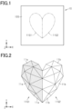
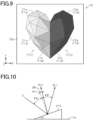
- Fig. 1 shows an optical structure 10 having a structure surface 10S which includes a first display region group 11G1 and a second display region group 11G2.
- Each display region group produces an image unique thereto in one observation direction. In other words, each display region group displays an image unique thereto in a display direction.
- An image produced by the first display region group 11G1 is a first image
- an image produced by the second display region group 11G2 is a second image.
- the structure surface 10S serves as a surface for the first and second display region groups 11G1 and 11G2 to display images unique to the respective groups.
- the structure surface 10S includes two display region groups. However, the structure surface 10S may include three or more display region groups, and images unique to the respective groups may be displayed on the structure surface 10S.
- the structure surface 10S may be flat or curved.
- the structure surface 10S has one direction that is the X direction and another direction that is the Y direction perpendicular to the X direction.
- the direction perpendicular to the X-Y plane that is defined by the X and Y directions is the Z direction.
- a shape of a heart is formed by the first and second display region groups 11G1 and 11G2.
- the first and second display region groups 11G1 and 11G2 are adjacent to each other in the X direction.
- the first display region group 11G1 has a shape of one half of the heart shape obtained by cutting it perpendicularly to the X direction
- the second display region group 11G2 has a shape of the other half of the heart shape.
- the first and second images each produce an image that is a part of one complete shape.
- the first and second images match each other to produce a motif.
- the two display region groups may each display one entire shape, or the two groups do not have to display any shape at all.
- the two groups may each display one entire shape, with the first display region group 11G1 displaying the shape using polygonal faces, and with the second display region group 11G2 displaying the shape using wire frame shapes.
- the second display region group 11G2 may be included in the first display region group 11G1, with the first display region group 11G1 alone displaying one entire shape, and with the second display region group 11G2 not contributing to the shape.
- the display region groups may have individual shapes.
- the display region groups may each have a shape of an entire or an independent portion of a decorative pattern, a mark, a symbol, a logo, a character, a pictorial symbol, an icon, an emblem or a heraldic emblem.
- the display region groups In plan view perpendicular to the structure surface 10S, the display region groups respectively have contours which are equal to those of the images produced by the respective display region groups.
- Fig. 2 is an enlarged plan view illustrating the structures of the first and second display region groups 11G1 and 11G2.
- display regions of the first display region group 11G1 are dotted to easily distinguish them from the display regions of the second display region group 11G2.
- the first display region group 11G1 is configured by a plurality of first display regions 11a
- the second display region group 11G2 is configured by a plurality of second display regions 11b.
- the first display regions 11a are disposed in a region on the structure surface 10S so as not to overlap with the region in which the second display regions 11b are disposed.
- the region defined by the contour of the first display region group 11G1 does not overlap with the region defined by the contour of the second display region group 11G2.
- the display regions each have a polygonal shape. As shown in Fig. 2 , the display regions each have a triangular shape in the present embodiment. Besides a triangular shape, the display regions may each have a square or pentagonal shape. In each display region group, the display regions may have two or more different polygonal shapes.
- the plurality of display regions configuring each display region group include several types that are different from each other at least in shape or size. It should be noted that the expression “different from each other in shape” refers to similar polygons having side lengths or angles that are different among the polygons.
- the adjacently located display regions are in contact with each other. Specifically, in each display region group, two adjacently located display regions share one side defining these regions.
- the optical structure 10 produces a vector image with the first display regions 11a and the second display regions 11b, that is, an assembly of regions expressed by vectors.
- Each display region has an area or a size which is visually recognizable to the naked eye of the observer of the optical structure 10.
- Each display region has an area of 0.1 mm 2 or more and 0.5 mm 2 or less, visually recognizable to the naked eye.
- Each display region group may include display regions with different areas.
- each display region will be described more specifically. Although the region where the first display regions 11a are provided on the structure surface 10S is different from the region where the second display regions 11b are provided thereon, the structure of each reflective surface is common between the former region and the latter region. Accordingly, the following description will be focused on the first display regions 11a, omitting description for the second display regions 11b.
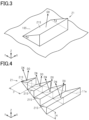
- each of the reflective surfaces 21S provided to each first display region 11a corresponds to a face of a scale mirror 21.
- the scale mirror 21 extends in one direction. It should be noted that Fig. 3 shows an example of a scale mirror 21 extending in the X direction.
- the reflective surface 21S is an optical surface extending parallel to a plane intersecting the structure surface 10S.
- the angle formed between the reflective surface 21S and the structure surface 10S is an inclination angle ⁇ which is constant in the direction in which the scale mirror 21 is elongated.
- Each reflective surface 21S is a mirror surface which causes mirror reflection of visible light, and specularly reflects light incident on the reflective surface 21S in a direction conforming to the inclination angle ⁇ .
- the angle between the direction normal to the reflective surface 21S and the travel direction of light entering the reflective surface 21S is an incidence angle of light.
- Light is not incident on each reflective surface 21S from one direction but from directions over a particular range. This is because light incident on each reflective surface 21S emerges from a light source having some size. Accordingly, light is incident on a point of the reflective surface 21S from directions over a particular range that depends on the size of and the distance to the light source. Thus, the incidence angle has a particular range.
- Each reflective surface 21S reflects light incident thereon. When the optical structure is observed under normal conditions, the observation direction DO is also within a particular range.
- the observation direction DO defined by the particular range and the distance to the reflective surface from the observation point has a particular range.
- the respective reflective surfaces 21S in each display region group have shapes where the specific observation direction DO, i.e., a direction common to the plurality of reflective surfaces 21S, includes the reflection direction, i.e. emerging direction, of light that is incident on the reflective surfaces 21S over the particular range and emerges therefrom.
- the scale mirror 21 may be a projection on the structure surface 10S having a triangular prism shape, or may be a recess in the structure surface 10S having a reflective surface 21S.
- the reflective surface 21S of each scale mirror 21 may be an optical interference coating surface.
- the optical interference coating is configured by one or more dielectric layers.
- reflected light with a given wavelength will be intensified due to differences in refractive index between the boundaries of the plurality of dielectric layers contacting each other in the direction in which they are overlapped, and reflected light with a wavelength other than that will be cancelled due to the differences.
- the optical structure 10 can produce an image which has colors conforming to the wavelengths of light reflected by the multiple interference layers.
- the plurality of dielectric layers may have a configuration in which a plurality of laminates, each including one high refractive index layer and one low refractive index layer, are overlapped with each other.
- the material for forming the high refractive index layer may be tantalum oxide, and the material for forming the low refractive index layer may be silicon oxide.
- each first display region 11a includes a plurality of reflective surfaces 21S.
- Each reflective surface 21S reflects light, which is incident on the structure surface 10S, into an angular range including the observation direction DO of which there is one per display region group.
- each first display region 11a includes a plurality of reflective surfaces 21S each of which reflects light incident on the structure surface 10S toward a direction within a predetermined angular range including the observation direction DO.
- the plurality of reflective surfaces 21S are arranged at a given pitch P in a direction in which they are arranged.
- the pitch P in this case is 1 ⁇ m or more and 300 ⁇ m or less.
- Fig. 4 shows, as an example, a plurality of reflective surfaces 21S provided to one first display region 11a and arranged in the Y direction.
- the pitch P is 1 ⁇ m or more in this configuration, the plurality of reflective surfaces 21S do not produce diffracted light that is in the wavelength range of visible light. Therefore, the image displayed by the optical structure 10 is produced by light emerging from the individual reflective surfaces 21S, i.e., produced by white light which is based on specular reflection mentioned above. Also, since the pitch P is 300 ⁇ m or less, which is smaller than the resolution of the human eye, the reflective surfaces 21S of each first display region 11a are unlikely to be visually recognized by the observer of the optical structure 10.
- the effects, as mentioned above, due to the pitch P being 1 ⁇ m or more and 300 ⁇ m or less can be obtained from all over the first display region 11a, compared to the configuration having various pitches P.
- the first image displayed by the first display region group 11G1 is easily visually recognized as an assembly of image segments produced by the respective first display regions 11a.
- each reflective surface 21S has one normal direction DN. As described above, each reflective surface 21S reflects light in the observation direction DO. In each first display region 11a, the normal direction DN of each reflective surface 21S is equal to the normal directions of other reflective surfaces 21S. As seen perpendicularly to the first display region 11a, the normal direction DN of each reflective surface 21S is the direction in which the reflective surface 21S is oriented.
- the first display region group 11G1 includes first display regions 11a whose normal directions DN of the reflective surfaces 21S are different from each other. Specifically, the first display region group 11G1 includes a plurality of directions as the normal directions DN of the reflective surfaces 21S. In other words, among the plurality of first display regions 11a, some have normal directions DN of the reflective surface 21S which are different from those of others.
- each display region 11a has a triangular shape and is enclosed by three other first display regions 11a.
- Each triangular display region 11a shares its respective sides with the three display regions 11a and is defined by them.
- the normal direction DN of the reflective surfaces 21S of each first display region 11a may be different from those of the reflective surfaces 21S of the first display regions 11a that it shares sides with.
- at least two first display regions 11a may have the same normal directions DN of the reflective surfaces 21S.
- the normal directions DN of the reflective surfaces 21S may be different from each other.
- the image produced by the optical structure 10 can be easily recognized as a three-dimensional image.
- Each first display region 11a has a normal direction DN of the reflective surfaces 21S and the normal direction DN may be located on the inside of the group of normal directions DN of the reflective surfaces 21S of the first display regions 11a enclosing this first display region 11a.
- a normal direction DN can be expressed by a sum of a group of normal directions DN.
- the coefficient has a positive value.
- the optical structure 10 can display a more natural three-dimensional image.
- the optical structure 10 does not have to include the first display regions 11a all satisfying the requirements described above, but may include only several first display regions 11a satisfying the requirements.
- the distance between the reflective surface 21S and the structure surface 10S i.e., between the reflective surface 21S and the first display region 11a included in the structure surface 10S, has a maximum height H.
- the reflective surfaces 21S have a constant height H.
- the height H of each reflective surface 21S is equal to those of other reflective surfaces 21S. Since the heights H of all the reflective surfaces 21S are equal to each other in each first display region 11a, the plurality of reflective surfaces 21S of the first display region 11a can be easily formed, compared to the configuration in which the reflective surfaces 21S have several different heights H. Furthermore, according to the structure where all the reflective surfaces 21S have heights H equal to each other, the reflective surfaces 21S can be formed with high accuracy in shape in the production process.
- the ratio of the minimum height H to the maximum height H of the reflective surfaces 21S is 50% or more. In other words, for the first display region group 11G1, the ratio of the minimum height H to the maximum height H is 50% or more.
- difference in intensity of light reflected from the plurality of reflective surfaces 21S for producing an image is prevented from becoming excessively large among the reflective surfaces 215. Therefore, the image produced by the first display region group 11G1 is prevented from not being recognized as one image.
- each first display region 11a the reflective surfaces 21S have one normal direction DN.
- the plurality of reflective surfaces 21S belonging to each first display region 11a reflect light in the observation direction DO to produce one first image segment C1a.
- the plurality of reflective surfaces 21S can produce one first image segment C1a in each first display region 11a.
- the first image segment C1a has a shape in which the plurality of reflective surfaces 21S are combined in a direction in which they are arranged. Specifically, in plan view perpendicular to the structure surface 10S, the first image segment C1a has an area that is equal to the sum of areas of the plurality of reflective surfaces 21S.
- the inclination angle ⁇ of the first image segment C1a relative to the first display region 11a that is the structure surface 10S in other words is equal to the inclination angle ⁇ of each reflective surface 21S relative to the structure surface 10S.
- the maximum distance between the first image segment C1a and the structure surface 10S corresponds to a height HP of the first image segment C1a.
- the height HP is equal to a value obtained by multiplying the height H of the reflective surface 21S by the number of reflective surfaces 21S.
- the first display region 11a can produce one first image segment C1a with light emerging from the plurality of reflective surfaces 21S belonging to this first display region 11a.
- One first image segment C1a corresponds to an image which emerges from one phantom plane covering one entire first display region 11a and forming a predetermined angle relative to the first display region 11a.
- the reflective surfaces 21S are arranged at a pitch of 1 ⁇ m or more and thus no diffracted light emerges from the reflective surfaces 21S. Accordingly, light emerging from the plurality of reflective surfaces 21S easily produces one first image segment C1a. Furthermore, since the reflective surfaces 21S are arranged at a pitch of 300 ⁇ m or less, the reflective surfaces 21S are unlikely to be visually recognized by the observer. Thus, the observer can easily visually recognize the first image segment C1a.
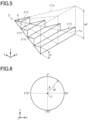
- Figs. 4 and 5 each show, as an example, a first display region 11a provided with four scale mirrors 21.
- the number of the scale mirrors 21, i.e., the number of the reflective surfaces 21S, of one first display region 11a may be three or less, or may be five or more.
- some may include different numbers of reflective surfaces 21S than others.
- Fig. 6 shows a projection direction DP that is a direction (unit vector) in which the normal direction DN (normal vector) of the reflective surfaces 21S is projected onto the structure surface 10S of the optical structure 10.
- the angle of the projection direction DP relative to a reference direction in the structure surface 10S is an azimuth angle ⁇ of the reflective surfaces 21S.
- the reference direction is the Y direction.
- one azimuth angle ⁇ is provided to each first display region 11a.
- the plurality of reflective surfaces 21S belonging to each first display region 11a are configured to produce one first image segment C1a.
- the plurality of reflective surfaces 21S belonging to each first display region 11a are configured to produce one first image segment C1a.
- the first display region group 11G1 includes first display regions 11a whose azimuth angles ⁇ of the reflective surfaces 21S are different from each other.
- the plurality of first display regions 11a include a set of first display regions 11a in which the azimuth angles ⁇ are different from each other.
- the number of first display regions 11a included in the first display region group 11G1 is n
- the number of first display regions 11a included in a set is 2 or more and n or less.
- the first display region group 11G1 is configured to produce an image unique thereto in the observation direction DO, based on the first image segments C1a to be produced by the respective first display regions 11a.
- an image displayed by the first display region group 11G1 is visually recognized.
- an image displayed by the second display region group 11G2 is visually recognized.
- these images are each configured by the image segments produced by light that has emerged from a phantom plane covering one entire display region, while the image segments are each produced by light having an intensity conforming to the azimuth angle ⁇ of the reflective surfaces 21S forming the image segment.
- the first and second display region groups 11G1 and 11G2 produce respective three-dimensional images each based on the difference in brightness among the image segments, and these images are produced in respective observation directions DO different from each other. Consequently, the optical structure 10 will have a high-quality appearance. In this way, the optical structure 10 as a motif will have high quality. Moreover, the optical structure 10 will be impressive to the observer.
- the azimuth angle ⁇ is 0° or more and less than 360°.
- the azimuth angle ⁇ of the reflective surfaces 21S is 0°.
- the point where the direction having an azimuth angle ⁇ of 0° intersects the direction having an azimuth angle ⁇ of 90° is the origin O.
- the optical structure 10 is configured such that the observation direction DO of the first display region group 11G1 is different from that of the second display region group 11G2 by respectively using the azimuth angles ⁇ of the reflective surfaces 21S of the first display regions 11a and the azimuth angles ⁇ of the reflective surfaces 21S of the second display regions 11b.
- the optical structure 10 is configured such that the images unique to the first and second display region groups 11G1 and 11G2, respectively, are different from each other in brightness, when the eyepoint is at a predetermined position relative to the structure surface 10S, i.e., when the structure surface 10S is observed from a predetermined direction.
- the reflective surfaces 21S of the first display regions 11a correspond to the first reflective surfaces
- the reflective surfaces 21S of the second display regions 11b correspond to the second reflective surfaces.
- first reflective surfaces Since the range of azimuth angles ⁇ of the first reflective surfaces is different from that of the second reflective surfaces, light reflected from the first reflective surfaces and light reflected from the second reflective surfaces are unlikely to be simultaneously visually recognized by an observer OB. Specifically, the image produced by the first reflective surfaces and the image produced by the second reflective surfaces are unlikely to be simultaneously visually recognized by the observer. Accordingly, a first image PIC1 produced by the first display region group 11G1 and a second image PIC2 produced by the second display region group 11G2 are easily visually recognized independently.
- the azimuth angles ⁇ of the first reflective surfaces are in a first range ⁇ 1, while the azimuth angles of the second reflective surfaces are in a second range ⁇ 2 which is different from the first range ⁇ 1.
- the first range ⁇ 1 is a predetermined range that is 0° or more and less than 180°
- the second range ⁇ 2 is a predetermined range that is 180° or more and less than 360°.
- the optical structure 10 is tilted such that the portion of the structure surface 10S intersecting the plane and the portion of the plane intersecting the structure surface 10S both remain unchanged.
- tilting of the optical structure 10 allows the image displayed by the optical structure 10 to change between the first image produced by the first display region group 11G1 and the second image produced by the second display region group 11G2.
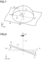
- Fig. 7 shows a hemisphere protruding in the Z direction from the structure surface 10S.
- the angle formed between the normal direction DN of the reflective surfaces 21S and the projection direction DP that is a projection of the normal direction DN onto the structure surface 10S is an elevation angle ⁇ e that is an angle formed if one looks upward from the origin O along the normal direction DN in the structure surface 10S.
- the angle formed between the normal direction DN of the reflective surfaces 21S and the Z direction is a zenith angle ⁇ z.
- a state in which the optical structure 10 is disposed parallel to the X-Y plane is referred to as a reference state.
- the projection direction DP of each reflective surface 21S in the reference state is referred to as a reference projection direction.
- the observer of the optical structure 10 tilts the optical structure 10
- the observer will tilt the optical structure 10 such that the normal direction DN and the reference projection direction of each reflective surface 21S change in the range of about 0° to about 180°.
- the observer may tilt the optical structure 10 longitudinally, or the observer may tilt it laterally.
- the expression “tilt the optical structure 10 longitudinally” refers to the optical structure 10 being tilted in the Y direction such that the angle formed between the normal direction DN and the reference projection direction in each reflective surface 21S changes. In other words, the expression refers to the optical structure 10 being tilted such that the portion of the X-Z plane intersecting the optical structure 10 and the portion of the optical structure 10 intersecting the X-Z plane both remain unchanged.
- the expression “tilt the optical structure 10 laterally” refers to the optical structure 10 being tilted in the X direction such that the angle formed between the normal direction DN and the reference projection direction in each reflective surface 21S changes. In other words, the expression refers to the optical structure 10 being tilted such that the portion in the Y-Z plane intersecting the optical structure 10 and the portion in the optical structure 10 intersecting the Y-Z plane both remain unchanged.
- each first display region 11a includes vertical surfaces, inclined surfaces, flat surfaces or scattering surfaces, in addition to the plurality of reflective surfaces 21S.
- the vertical surfaces or the inclined surfaces connect the reflective surfaces 21S to the structure surface 10S, and are included in the respective scale mirrors 21.
- the flat surfaces or the scattering surfaces are placed in regions where the reflective surfaces 21S are not placed, in plan view perpendicular to the structure surface 10S.
- the surfaces connecting between the respective reflective surfaces 21S to the structure surface 10S are vertical surfaces, the area of the reflective surfaces 21S can be maximized in each first display region 11a.
- each first display region 11a is configured to include inclined surfaces or flat surfaces, the area of the reflective surfaces 21S can be modulated by changing the angle of the inclined surfaces or changing the area of the flat surfaces.
- each first display region 11a includes scattering surfaces
- the area of the reflective surfaces 21S can be modulated, and scattering light can be permitted to emerge in directions different from the reflective surfaces 21S.
- the quantities of light reflected from the respective first display regions 11a may be made different from each other.
- the optical structure 10 may include first display regions 11a provided with vertical surfaces, and first display regions 11a provided with inclined surfaces or flat surfaces or scattering surfaces.
- first display regions 11a provided with inclined surfaces or flat surfaces or scattering surfaces.
- the area of the reflective surfaces 21S may be made different among the first display regions 11a, owing to which the quantity of reflected light may be made different among the first display regions 11a, resultantly achieving much richer expression.
- Figs. 9 and 14 each show brightness, or light and dark in other words, in images respectively formed by the display region groups, by gradation of colors imparted to the respective groups. In Figs. 9 and 14 , color gradations are imparted such that portions of the images having lower brightness are given darker color.
- the observer OB is observing the optical structure 10 in the reference state, i.e., the optical structure 10 disposed parallel to the X-Y plane, from a direction of the observer's line of sight which is included in the Y-Z plane and is normal to the X-Y plane.
- the observer OB laterally tilts the optical structure 10 without changing the position and direction of observing the optical structure 10.
- the observer OB tilts the optical structure 10 rightward.
- the observer OB tilts the optical structure 10 so as to be lowered more in the 90° direction of the azimuth angle ⁇ than in the 270° direction of the azimuth angle ⁇ , with reference to the Z direction. More specifically, the observer OB tilts the optical structure 10 such that the region in the structure surface 10S including the first display regions 11a comes closer to the observer OB than does the region including the second display regions 11b.
- the observer OB can visually recognize the first image PIC1 produced by the first display region group 11G1.
- the first image PIC1 is configured by the first image segments C1a respectively produced by the plurality of first display regions 11a. Therefore, the first image PIC1 produced by the first display region group 11G1 is visually recognized by the observer as a three-dimensional image due to difference in brightness among the first image segments C1a configuring the first image PIC1.
- each first image segment C1a has brightness that is higher than the brightness of any one of the second image segments C2a.
- the second image segments C2a of the second image PIC2 have substantially the same brightness.
- the second image PIC2 is visually recognized as a planar image having a uniform appearance.
- a more specific description will be given of a relationship between the normal direction DN of the reflective surfaces 21S and quantity of light per unit area emerging from each reflective surface 21S. This specific description will explain the reason why the first image PIC1 is visually recognized as a three-dimensional image, while the second image PIC2 is visually recognized as a planar image.
- the following description will be given by way of an example the reflective surfaces 21S provided to each first display region 11a. The same applies to the reflective surfaces 21S provided to each second display region 11b.
- Fig. 10 shows an example of a reflective surface 21S of a first display region 11a.
- the reflective surface 21S has an inclination angle ⁇ , i.e., a first inclination angle ⁇ 1, relative to the first display region 11a.
- Fig. 11 shows an example of a reflective surface 21S of another first display region 11a.
- the reflective surface 21S has an inclination angle ⁇ , i.e., a second inclination angle ⁇ 2, relative to the first display region 11a.
- the second inclination angle ⁇ 2 is larger than the first inclination angle ⁇ 1.
- incident light IL which arrives from a predetermined direction is incident on the reflective surface 21S whose inclination angle ⁇ is the first inclination angle ⁇ 1.
- the angle formed between the direction of incidence of the incident light IL and the normal direction DN is an incidence angle of the incident light IL
- the angle formed between the light emerging from the reflective surface 21S and the normal direction DN is an emerging angle.
- the incidence angle of the incident light IL at the reflective surface 21S is a first incidence angle ⁇ 1
- the emerging angle of first specular reflected light RL1 in the reflective surface 21S is a first emerging angle ⁇ 1.
- the first incidence angle ⁇ 1 is equal to the first emerging angle ⁇ 1.
- the light reflected in the observation direction DO is a first light component PL1 having an emerging angle that is a first emerging angle ⁇ 1.
- the incident light IL is incident on the reflective surface 21S, whose inclination angle ⁇ is the second inclination angle ⁇ 2, at a second incidence angle ⁇ 2 which is smaller than the first incidence angle ⁇ 1.
- the reflective surface 21S reflects second specular reflected light RL2 at an emerging angle ⁇ 2. Since the second incidence angle ⁇ 2 is equal to the second emerging angle ⁇ 2, the second emerging angle ⁇ 2 is smaller than the first emerging angle ⁇ 1.
- the light emerging in the observation direction DO is a second light component PL2 having an emerging angle that is a second emerging angle ⁇ 2.
- the quantity of light of the light components per unit area increases as the difference between the emerging angle of the light components and the emerging angle of specular reflected light decreases. Comparing the reflective surface 21S having the first inclination angle ⁇ 1 with the reflective surface 21S having the second inclination angle ⁇ 2, the difference between the first emerging angles ⁇ 1 and ⁇ 1 is larger than the difference between the second emerging angles ⁇ 2 and ⁇ 2. Therefore, quantity of light of the first light components PL1 per unit area is smaller than that of the second light components PL2 per unit area.
- the first image PIC1 formed of the plurality of first image segments C1a is produced as a three-dimensional image due to the inclination angles ⁇ and the azimuth angles ⁇ of the reflective surfaces 21S of the display regions.
- the second image PIC 2 formed of the plurality of image segments C2a is visually recognized as a planar image having a uniform appearance.
- first display regions 11a each have a triangular shape
- first image segments C1a each have a triangular shape.
- the first image PIC1 to be displayed by the optical structure 10 can be produced. In this way, the image formed on the optical structure 10 is easily recognized as an image expressing a curved surface of a three-dimensional object.
- the observer OB is observing the optical structure 10 of the reference state from a direction of the observer's line of sight which is included in the Y-Z plane and is normal to the X-Y plane.
- the observer OB tilts the optical structure 10 leftward without changing the position and direction of observation of the optical structure 10.
- the observer OB tilts the optical structure 10 so as to be lowered more in the 270° direction of the azimuth angle ⁇ than in the 90° direction of the azimuth angle ⁇ , with reference to the Z direction. More specifically, the observer OB tilts the optical structure 10 such that the region of the structure surface 10S including the second display regions 11b comes closer to the observer OB than does the region including the first display regions 11a.
- the observer OB can visually recognize the second image PIC2 produced by the second display region group 11G2.
- the second image PIC2 is configured by the second image segments C2a respectively produced by the plurality of second display regions 11b. Therefore, the second image PIC2 produced by the second display region group 11G2 is visually recognized by the observer as a three-dimensional image due to difference in intensity of light among the second image segments C2a configuring the second image PIC2.
- each second image segment C2a configuring the second image PIC2 has brightness that is higher than the brightness of any one of the first image segments C1a.
- the first image PIC1 is visually recognized as a planar image having a uniform appearance.
- the second image PIC2 formed of the plurality of second image segments C2a is produced as a three-dimensional image due to the inclination angles ⁇ and the azimuth angles ⁇ of the reflective surfaces 21S of the display regions.
- the first image PIC1 formed of the plurality of first image segments C1a is visually observed as a planar image having a uniform appearance.
- second image segments C2a each have a triangular shape.
- the second image PIC2 to be displayed by the optical structure 10 can be produced. In this way, the image formed on the optical structure 10 is easily recognized as an image expressing a curved surface of a three-dimensional object.
- the difference in light intensity between the first and second images PIC1 and PIC2 when the optical structure 10 is laterally tilted relative to the reference state can be made larger by setting the first and second ranges ⁇ 1 and ⁇ 2 as follows. With this setting, one image is visually recognized as a three-dimensional image and the other image is visually recognized as a planar image. Specifically, the difference between the maximum value in the first range ⁇ 1 and the minimum value in the second range ⁇ 2 may be set to 90° or more, and the difference between the maximum value in the second range ⁇ 2 and the minimum value in the first range ⁇ 1 may be set to 90° or more.
- the first range ⁇ 1 may be 45° or more and 135° or less, and the second range ⁇ 2 may be 225° or more and 315° or less.
- the first range ⁇ 1 may be 30° or more and 45° or less, and the second range ⁇ 2 may be 210° or more and 225° or less.
- the optical structure 10 described above can be produced through a method, for example, including a step of forming an uneven structure layer and a step of forming a reflective layer on a surface of the uneven structure layer.
- the uneven structure layer is replicated from a mold.
- the original plate is obtained by applying a photosensitive resist onto a surface of a plate-like substrate, and then radiating a beam onto the photosensitive resist for partial exposure thereof, followed by developing the photosensitive resist. Then, the original plate is electroformed to produce a metal stamp which is used as a matrix for forming an uneven structure layer.
- a metal stamper may also be produced by cutting a metal substrate by using a lathe technique.
- the uneven structure layer may be formed, for example, by thermal embossing, casting or photopolymerization.
- photopolymerization When photopolymerization is used, a radiation curable resin is castbetween a flat film carrier and a metal stamper. Then, the radiation curable resin is cured by applying radiation, and then the cured resin layer is released from the metal stamper together with the carrier.
- photopolymerization achieves higher structural precision on the scale mirrors 21 and easily provides scale mirrors 21 having higher thermal resistance and chemical resistance.
- various resins may be used as a material for forming the uneven structure layer.
- the material for forming the uneven structure layer may further contain at least one of a curing agent, a plasticizer, a disperser, various leveling agents, a UV absorber, an antioxidant, a viscosity modifier, a lubricant, a colorant, a light stabilizer, and the like.
- the resin may be a UV curable resin, a thermoplastic resin or a thermosetting resin.
- the UV curable resin may be a monomer, an oligomer or a polymer having an ethylenically unsaturated bond or an ethylenically unsaturated group.
- the monomer having an ethylenically unsaturated bond or an ethylenically unsaturated group may be 1,6-hexanediol, neopentyl glycol diacrylate, trimethylolpropane triacrylate, pentaerythritol triacrylate, pentaerythritol tetraacrylate, dipentaerythritol pentaacrylate or dipentaerythritol hexaacrylate.
- the oligomer having an ethylenically unsaturated bond or an ethylenically unsaturated group may be an epoxy acrylate, urethane acrylate or polyester acrylate.
- the polymer having an ethylenically unsaturated bond or an ethylenically unsaturated group may be a urethane-modified acrylic resin or an epoxy-modified acrylic resin.
- the UV curable resin may be an acrylic resin, an acrylic acrylate resin, an epoxy acrylate resin, a urethane acrylate resin, a polyester acrylate resin or an ethylene methacrylate resin.
- the thermoplastic resin may be an acrylic resin, an epoxy resin, a cellulose resin or vinyl resin.
- the thermosetting resin may be a urethane resin, a melamine resin, an epoxy resin or a phenol resin.
- the colorant may be a pigment or a dye.
- the pigment may be an inorganic pigment or an organic pigment.
- the pigment may also be a fluorescent pigment, a pearl pigment or a magnetic pigment.
- the dye may be a natural dye or a synthetic dye.
- the dye may also be a fluorescent dye.
- the resin materials for forming the uneven structure layer may be used singly or in combination of two or more.
- the reflective layer may be formed by deposition.
- the deposition used for forming the reflective layer may be physical vapor deposition including vacuum deposition, sputtering, ion plating and ionized cluster beam deposition, or chemical vapor deposition including plasma chemical vapor deposition, thermochemical vapor deposition and photochemical vapor deposition.
- vacuum deposition or ion plating has higher productivity than other methods and can easily form a reflective layer having good quality.
- the processing conditions may be determined depending on the material for forming the reflective layer.
- the material for forming the reflective layer may be metal or silicon, singly used, or an alloy or a compound. Of the metal or silicon, the metal may be aluminum, gold, silver, platinum, nickel, tin, chromium, titanium or zirconium.
- the reflective layer may be a multilayer optical interference coating in which the above materials are alternately deposited.
- the material for forming the multilayer optical interference coating may be zinc oxide or zinc sulfide. If either aluminum or silver is used as a material for forming the reflective layer, high reflectance is easily achieved in a visible light region.
- the ratio of the minimum height H to the maximum height H of the reflective surfaces 21S may be less than 50%.
- each reflective surface 21S in each display region does not have to be equal to those of other reflective surfaces 21S therein.
- the first range ⁇ 1 may be a predetermined range included in 90° or more and less than 270°
- the second range ⁇ 2 may be a predetermined range included in a range of 0° or more and less than 90° and a range of 270° or more and less than 360°.
- the optical structure 10 may be tilted such that the portion of the structure surface 10S intersecting the plane and the portion of the plane intersecting the structure surface 10S both remain unchanged.
- the optical structure 10 is tilted such that the portion of the structure surface 10S intersecting the plane and the portion of the plane intersecting the structure surface 10S both remain unchanged.
- tilting of the optical structure 10 allows the image displayed by the optical structure 10 to change between the first image PIC1 produced by the first display region group 11G1 and the second image PIC2 produced by the second display region group 11G2.
- the pitch P of arranging the reflective surfaces S21 does not have to be constant in the direction in which the reflective surfaces 21S are arranged, but the average of pitches P of arranging the reflective surfaces 21S is in the range of 1 ⁇ m or more and 300 ⁇ m or less.
- a minimum pitch P and a maximum pitch P are in the range of 1 ⁇ m or more and 300 ⁇ m or less.
- the most frequent pitch P is in the range of 1 ⁇ m or more and 300 ⁇ m or less.
- Each scale mirror 21 may have two reflective surfaces instead of one.
- a scale mirror 31 may be provided with a first reflective surface 31S1 and a second reflective surface 31S2.
- the first and second reflective surfaces 31S1 and 31S2 share one side defining these reflective surfaces.
- the first reflective surface 31S1 has a first inclination angle ⁇ a relative to the structure surface 10S
- the second reflective surface 31S2 has a second inclination angle ⁇ b relative to the structure surface 10S.
- the first inclination angle ⁇ a is smaller than the second inclination angle ⁇ b; however the former may be larger than or equal to the latter.
- one image segment may be produced per display region provided with a plurality of scale mirrors 31, either by the plurality of unidirectionally oriented first reflective surfaces 31S1, or the plurality of unidirectionally oriented second reflective surfaces 31S2.
- the first display regions 11a and the second display region 11b may each have a shape defined by a curved line or a shape defined by curved lines and straight lines.
- the shape defined by a curved line may be a circular shape, an elliptic shape, or the like.
- the shape defined by curved lines and straight lines may be a semi-circular shape, a semi-elliptic shape, or the like.
- the plurality of first display regions 11a or the plurality of second display regions 11b may include at least either display regions each defined by a curved line or display regions each defined by curved lines and straight lines, in addition to the display regions each having a polygonal shape.
- the plurality of first display regions 11a or the plurality of second display regions 11b may be configured by both of display regions each defined by a curved line and display regions each defined by curved lines and straight lines.
- advantageous effects as in item (1) may be achieved, as long as the observation direction DO of the first display region group 11G1 is configured to be different from the observation direction DO of the second display region group 11G2.
- the inclination angle ⁇ may be varied in the direction in which the reflective surface 21S extends, instead of being constant in the extending direction.
- each reflective surface 21S may have a base end portion in the direction in which the reflective surface 21S extends and a tip end portion that is the other end portion.
- the base end portion of the reflective surface 21S has an inclination angle ⁇ that is a base end inclination angle
- the tip end portion has an inclination angle that is a tip end inclination angle.
- the base end inclination angle may be larger than the tip end inclination angle, so that the inclination angle ⁇ of the reflective surface 21S monotonically decreases from the base end portion toward the tip end portion.
- the base end inclination angle may be smaller than the tip end inclination angle, so that the inclination angle ⁇ of the reflective surface 21S monotonically increases from the base end portion toward the tip end portion.
- the structure surface 10S may be provided with a plurality of pixels, and each display region may be one pixel.
- the plurality of pixels may be arranged in a matrix pattern on the structure surface 10S.
- the image displayed by the optical structure 10 is not limited to a vector image, but may be a raster image expressed by repetition of pixels as a unit area. With this configuration, the structure of each display region can be designed based on a raster image.
- the second embodiment is different from the first embodiment in the location of the display regions for displaying the first image and the location of the display regions for displaying the second image.
- the following description explains the differences in detail and omits detailed explanation for components common to the first embodiment.
- a configuration and an appearance of the optical structure will be sequentially explained.
- the second embodiment is a mode of the present disclosure and can be implemented in combination with the first embodiment described above. By combining the second embodiment with the first embodiment described above, functions of both the embodiments can be exerted. Combination of the second embodiment with the first embodiment described above can provide synergetic effects.
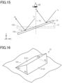
- Fig. 17 shows an optical structure 40 having a structure surface 40S.
- the structure surface 40S includes a first region 40A in which a first display region group 41G1 is provided, and a second region 40B in which a second display region group 41G2 is provided. Part of the first region 40A overlaps with part of the second region 40B.
- the first display region group 41G1 displays a first image and the second display region group 41G2 displays a second image. Display regions of the first image correspond to the first region 40A and display regions of the second image correspond to the second region 40B.
- the first region 40A has a heart-shaped contour and the second region 40B has a circular contour.
- the first display region group 41G1 has a configuration that is analogous to that of the second display region group 41G2.
- the first and second images have respective display region groups having configurations analogous to each other, and matching each other. These regions may each have a shape of a complete or an independent portion of a decorative pattern, a mark, a symbol, a logo, a character, a pictorial symbol, an icon, an emblem or a heraldic emblem, instead of a heart-shaped configuration or a circular configuration.
- a portion not overlapped with the second region 40B is an exclusive area 40A1 and a portion overlapping therewith is an overlap area 40A2.
- a portion not overlapped with the first region 40A is an exclusive area 40B1 and a portion overlapping therewith is an overlap area 40B2.
- the overlap area 40A2 of the first region 40A and the overlap area 40B2 of the second region 40B occupy the same area of the structure surface 40S.
- part of the region in which the first display region group 41G1 is provided overlaps with part of the region in which the second display region group 41G2 is provided. Therefore, one region where the two display region groups overlap each other in the structure surface 40S can display part of the first image displayed by the first display region group 40G1 and part of the second image displayed by the second display region group 41G2.
- the plurality of first display regions 11a belonging thereto have been arranged with no gap therebetween, and also in the second display region group 11G2, the plurality of second display regions 11b belonging thereto have been arranged with no gap therebetween.
- at least the overlap area 40A2 of the first region 40A i.e., the overlap area 40B2 of the second region 40B, includes portions where the first display regions belonging to the first display region group 41G1 are not provided and portions where the second display regions belonging to the second display region group 41G2 are not provided.
- Fig. 18 is an enlarged plan view of the site A that is a portion of the overlap area 40A2 of the first region 40A, i.e., a portion of the overlap area 40B2 of the second region 40B.
- the first display regions of the first display region group 41G1 are dotted to easily distinguish them from the second display regions of the second display region group 41G2.
- first display regions 41a of the first display region group 41G1 are mixed with second display regions 41b of the second display region group 41G2.
- the total area of the first display regions 41a may be made substantially equal to the total area of the second display regions 41b.
- the total quantity of light reflected from the first display regions 41a may be made substantially equal to the total quantity of light reflected from the second display regions 41b.
- the optical structure 40 may, for example, have a first range ⁇ 1 of 0° or more and less than 180° and a second range ⁇ 2 of 180° or more and less than 360°.
- the difference between the maximum value in the first range ⁇ 1 and the minimum value in the second range ⁇ 2 may be set to 90° or more
- the difference between the maximum value in the second range ⁇ 2 and the minimum value in the first range ⁇ 1 may be set to 90° or more.
- the individual images can be easily distinguished from each other.
- the reflective surfaces of the first display regions 41a correspond to the first reflective surfaces
- the reflective surfaces of the second display regions 41b correspond to the second reflective surfaces.
- the maximum dimension of a region where only the first reflective surfaces are provided is a first maximum dimension WM1
- the maximum dimension of a region where only the second reflective surfaces are provided is a second maximum dimension WM2.
- the first and second maximum dimensions WM1 and WM2 are each 300 ⁇ m or less.
- the first and second display regions 41a and 41b are provided on the structure surface 40S such that the first and second maximum dimensions WM1 and WM2 are both 300 ⁇ m or less.
- the largest one of the sides defining the first display region 41a is the first maximum dimension WM1. If at least one of the sides defining a first display region 41a is shared with another first display region 41a, the region occupied by these first display regions 41a sharing a side is a region where only the first reflective surfaces are provided. The maximum dimension of the region configured by these first display regions 41a is the first maximum dimension WM1.
- the largest one of the sides defining the second display region 41b is the second maximum dimension WM2. If at least one of the sides defining a second display region 41b is shared with another second display region 41b, the region occupied by these second display regions 41b sharing a side is a region where only the second reflective surfaces are provided. The maximum dimension of the region configured by these second display regions 41b is the second maximum dimension WM2.
- the observer Since the distances between the first and second reflective surfaces are 300 ⁇ m or less, which is not more than the resolution of the human eye, the observer is unlikely to distinguish the region where the first display region group 41G1 is provided from the region where the second display region group 41G2 is provided on the structure surface 40S. Therefore, while the observer is visually recognizing the image produced by the first display region group 41G1, or while the observer is visually recognizing the image produced by the second display region group 41G2, the other display region group not producing an image is unlikely to be visually recognized as a surface having poor-quality appearance. Consequently, the optical structure 40 will have a high-quality appearance. In this way, the optical structure 40 is imparted with high quality as a motif. Moreover, the optical structure 40 is impressive to the observer.
- first display regions 41a sandwiching at least one second display region 41b therebetween have a distance of 300 ⁇ m or less therebetween. Accordingly, the distance between the first image segments respectively produced by these first display regions 41a is substantially 300 ⁇ m or less. Thus, since the gaps between the first image segments are unlikely to be visually recognized by the observer, the regions where the first image segments are not provided are unlikely to be visually recognized by the observer in the first image produced by the plurality of first image segments.
- second display regions 41b sandwiching at least one first display region 41a therebetween have a distance of 300 ⁇ m or less therebetween. Accordingly, the distance between the second image segments respectively produced by these second display regions 41b is substantially 300 ⁇ m or less. Thus, since the gaps between the second image segments are unlikely to be visually recognized by the observer, the regions where the second image segments are not provided are unlikely to be visually recognized by the observer in the second image produced by the plurality of second image segments.
- each exclusive area 40A1 of the first region 40A a plurality of first display regions 41a are provided and no second display regions 41b are provided.
- each exclusive area 40B1 of the second region 40B a plurality of second display regions 41b are provided and no first display regions 41a are provided.
- each exclusive area 40A1 of the first region 40A a plurality of first display regions 41a may be arranged with no gap therebetween.
- a plurality of second display regions 41b may be arranged with no gap therebetween.
- the ratio of the first display regions 41a in the exclusive areas 40A1 may be made equal to the ratio of the first display regions 41a in the overlap area 40A2.
- the ratio of the second display regions 41b in the exclusive areas 40B1 may be made equal to the ratio of the second display regions 41b in the overlap area 40B2.
- Fig. 19 shows a first image PIC1 which is visually recognized when the optical structure 40 in the reference state is tilted rightward.
- Fig. 20 shows a second image PIC2 which is visually recognized when the optical structure 40 in the reference state is tilted leftward.
- each first image segment C1a and the size of each second image segment C2a are exaggerated.
- the shapes of the first image segments are not consistent with those of the first display regions 41a shown in Fig. 18
- the shapes of the second image segments are not consistent with those of the second display regions 41b shown in Fig. 18 .
- the first image PIC1 produced by the assembly of the plurality of first image segments C1a is visually recognized by the observer of the optical structure 40.
- each first image segment C1a will have brightness conforming to the inclination angle ⁇ and the azimuth angle ⁇ of the reflective surfaces of the first display region 41a forming the first image segment C1a.
- the first image PIC1 is visually recognized by the observer as a three-dimensional image.
- each second image segment C2a will have brightness conforming to the inclination angle ⁇ and the azimuth angle ⁇ of the reflective surfaces of the second display region 41b forming the second image segment C1a.
- the second image PIC2 is visually recognized by the observer as a three-dimensional image.
- the observer Since the distances between the first and second reflective surfaces are 300 ⁇ m or less which is not more than the resolution of the human eye, the observer is unlikely to distinguish the region where the first display region group 41G1 is provided from the region where the second display region group 41G2 is provided on the structure surface 40S. Therefore, while the observer is visually recognizing the first image PIC1 produced by the first display region group 41G1, or while the observer is visually recognizing the second image PIC2 produced by the second display region group 41G2, the other display region group not producing an image is unlikely to be visually recognized as a surface having a poor-quality appearance. Consequently, the optical structure 40 will have a high-quality appearance. In this way, the optical structure 40 is imparted with high quality as a motif. Moreover, the optical structure 40 is impressive to the observer.
- the first maximum dimensions WM1 and the second maximum dimensions WM2 may include values larger than 300 ⁇ m.
- the gaps between the image segments may be visually recognized in the first and second images PIC1 and PIC2; however, the first image PIC1 may still be switched to the second image PIC2, or vice versa, by tilting the optical structure 40.
- the optical structure 10 or 40 may be applied to paper or film media having printing thereon to obtain high quality printing (Fine Press).
- This high quality printing may be security printing.
- Security printing may be printing of authentication documents, valuable securities, banknotes, and the like. High quality printing can minimize forgery of security printing.
- By adhering the optical structure 10 or 40 to paper or film media having printing thereon high quality printing can be obtained.
- further printing may be provided thereon.
- the printing may be offset printing, gravure printing or screen printing. Printing can be conducted using an ink as a material.
- the ink may be a pigment ink or a dye ink.
- the ink may be a visible ink or an invisible ink.
- the invisible ink may be a fluorescent ink or an infrared absorbing ink.
Landscapes
- Physics & Mathematics (AREA)
- General Physics & Mathematics (AREA)
- Optics & Photonics (AREA)
- Engineering & Computer Science (AREA)
- Accounting & Taxation (AREA)
- Business, Economics & Management (AREA)
- Finance (AREA)
- Manufacturing & Machinery (AREA)
- Marketing (AREA)
- Theoretical Computer Science (AREA)
- Diffracting Gratings Or Hologram Optical Elements (AREA)
- Optical Elements Other Than Lenses (AREA)
- Credit Cards Or The Like (AREA)
- Stereoscopic And Panoramic Photography (AREA)
Claims (9)
- Optische Struktur, umfassend:
eine Strukturoberfläche (10S), die eine Vielzahl von Anzeigebereichsgruppen (11G) einschließlich einer ersten Anzeigebereichsgruppe (11G1) und einer zweiten Anzeigebereichsgruppe (11G2) einschließt, wobei jede der Anzeigebereichsgruppen eine Vielzahl von Anzeigebereichen (11a, 11b) aufweist, wobei:jeder Anzeigebereich jeder Anzeigebereichsgruppe eine Vielzahl von reflektierenden Oberflächen (21S) einschließt, die auf die Strukturoberfläche einfallendes Licht in eine Anzeigerichtung eines Bildes reflektieren, das für die Anzeigebereichsgruppe einzigartig ist, wobei die reflektierenden Oberflächen in einem durchschnittlichen Abstand von 1 µm oder mehr und 300 µm oder weniger in einer Richtung angeordnet sind, in der die reflektierenden Oberflächen angeordnet sind;in jedem Anzeigebereich eine Projektionsrichtung (DP) definiert ist, wobei die Projektionsrichtung eine Richtung ist, in der eine Normalrichtung zu den reflektierenden Oberflächen auf die Strukturoberfläche projiziert wird und einen Azimutwinkel (φ) relativ zu einer Referenzrichtung in der Strukturoberfläche aufweist, und die Vielzahl der reflektierenden Oberflächen, die zu dem Anzeigebereich gehören, ein Bild erzeugen;in jeder Anzeigebereichsgruppe die Vielzahl von Anzeigebereichen einen Satz von Anzeigebereichen einschließt, deren Azimutwinkel voneinander verschieden sind, und die Vielzahl von Anzeigebereichen ein Bild, das für die Anzeigebereichsgruppe einzigartig ist, in der Anzeigerichtung durch die Vielzahl von reflektierenden Oberflächen erzeugt, die zu jedem der Anzeigebereiche gehören;die Anzeigerichtung der ersten Anzeigebereichsgruppe sich von der Anzeigerichtung der zweiten Anzeigebereichsgruppe unterscheidet, um eine Helligkeit zu erzeugen, die sich zwischen dem Bild, das für die erste Anzeigebereichsgruppe eindeutig ist, und dem Bild, das für die zweite Anzeigebereichsgruppe eindeutig ist, in den jeweiligen Anzeigerichtungen der Bilder unterscheidet; unddie erste Anzeigebereichsgruppe und die zweite Anzeigebereichsgruppe einander entsprechen, um ein Motiv zu erzeugen; und dadurch gekennzeichnet ist, dassjeder Anzeigebereich eine Fläche von 0,1 mm2 oder mehr und 0,5 mm2 oder weniger aufweist. - Optische Struktur nach Anspruch 1, wobei:die Anzeigebereiche, die zu der ersten Anzeigebereichsgruppe gehören, erste Anzeigebereiche sind, und die reflektierenden Oberflächen, die für jeden der ersten Anzeigebereiche bereitgestellt sind, erste reflektierende Oberflächen sind;der Azimutwinkel der ersten reflektierenden Oberflächen in einem ersten Bereich liegt;die Anzeigebereiche, die zu der zweiten Anzeigebereichsgruppe gehören, zweite Anzeigebereiche sind, und die reflektierenden Oberflächen, die für jeden der zweiten Anzeigebereiche bereitgestellt sind, zweite reflektierende Oberflächen sind; undder Azimutwinkel der zweiten reflektierenden Oberflächen in einem zweiten Bereich liegt, der sich von dem ersten Bereich unterscheidet.
- Optische Struktur nach Anspruch 2, wobei:der Azimutwinkel einen Wert aufweist, der 0° oder mehr und weniger als 360° beträgt;der erste Bereich ein vorbestimmter Bereich ist, der 0° oder mehr und weniger als 180° beträgt; undder zweite Bereich ein vorbestimmter Bereich ist, der 180° oder mehr und weniger als 360° beträgt.
- Optische Struktur nach Anspruch 2, wobei:der Azimutwinkel einen Wert aufweist, der 0° oder mehr und weniger als 360° beträgt;der erste Bereich ein vorbestimmter Bereich ist, der 90° oder mehr und weniger als 270° beträgt; undder zweite Bereich ein vorbestimmter Bereich ist, der in einem Bereich liegt, der durch einen Bereich von 0° oder mehr und weniger als 90° und einen Bereich von 270° oder mehr und weniger als 360° konfiguriert ist.
- Optische Struktur nach Anspruch 2, wobei in der Strukturoberfläche mindestens ein Teil des Bereichs, in dem die erste Anzeigebereichsgruppe bereitgestellt ist, mit mindestens einem Teil des Bereichs, in dem die zweite Anzeigebereichsgruppe bereitgestellt ist, überlappt.
- Optische Struktur nach Anspruch 5, wobei in der Draufsicht senkrecht zur Strukturoberfläche ein Bereich, in dem nur die ersten reflektierenden Oberflächen bereitgestellt sind, eine maximale Abmessung von 300 µm oder weniger aufweist, und ein Bereich, in dem nur die zweiten reflektierenden Oberflächen bereitgestellt sind, eine maximale Abmessung von 300 µm oder weniger aufweist.
- Optische Struktur nach einem der Ansprüche 1 bis 6, wobei:ein maximaler Abstand zwischen den reflektierenden Oberflächen und der Strukturoberfläche eine Höhe der reflektierenden Oberflächen ist; unddie Höhe in jedem Anzeigebereich konstant ist.
- Optische Struktur nach einem der Ansprüche 1 bis 7, wobei:ein maximaler Abstand zwischen den reflektierenden Oberflächen und der Strukturoberfläche eine Höhe der reflektierenden Oberflächen ist; undin jeder Anzeigebereichsgruppe das Verhältnis zwischen einem Mindestwert der Höhe und einem Höchstwert der Höhe 50 % oder mehr beträgt.
- Optische Struktur nach einem der Ansprüche 1 bis 8, umfassend:mehrlagige Interferenzschichten, die jeweils durch eine Vielzahl von dielektrischen Schichten konfiguriert sind, wobeijede der mehrschichtigen Interferenzschichten so konfiguriert ist, dass sie Licht mit einer vorbestimmten Wellenlänge reflektiert, indem sie es ermöglicht, dass die Vielzahl von dielektrischen Schichten, die einander berühren, in einer Richtung, in der die dielektrischen Schichten laminiert sind, voneinander verschiedene Brechungsindizes aufweisen; unddie reflektierenden Oberflächen Oberflächen der mehrlagigen Interferenzschichten sind.
Applications Claiming Priority (2)
| Application Number | Priority Date | Filing Date | Title |
|---|---|---|---|
| JP2017064855A JP6879002B2 (ja) | 2017-03-29 | 2017-03-29 | 表示体 |
| PCT/JP2018/013483 WO2018181825A1 (ja) | 2017-03-29 | 2018-03-29 | モチーフとしての光学構造体 |
Publications (3)
| Publication Number | Publication Date |
|---|---|
| EP3605158A1 EP3605158A1 (de) | 2020-02-05 |
| EP3605158A4 EP3605158A4 (de) | 2020-03-25 |
| EP3605158B1 true EP3605158B1 (de) | 2024-09-25 |
Family
ID=63676437
Family Applications (1)
| Application Number | Title | Priority Date | Filing Date |
|---|---|---|---|
| EP18775243.1A Active EP3605158B1 (de) | 2017-03-29 | 2018-03-29 | Optische struktur als motiv |
Country Status (4)
| Country | Link |
|---|---|
| US (1) | US11300809B2 (de) |
| EP (1) | EP3605158B1 (de) |
| JP (1) | JP6879002B2 (de) |
| WO (1) | WO2018181825A1 (de) |
Families Citing this family (1)
| Publication number | Priority date | Publication date | Assignee | Title |
|---|---|---|---|---|
| DE102019003518A1 (de) * | 2019-05-17 | 2020-11-19 | Giesecke+Devrient Currency Technology Gmbh | Sicherheitselement mit optisch variablem Flächenmuster |
Citations (10)
| Publication number | Priority date | Publication date | Assignee | Title |
|---|---|---|---|---|
| DE102005061749A1 (de) | 2005-12-21 | 2007-07-05 | Giesecke & Devrient Gmbh | Optisch variables Sicherheitselement und Verfahren zu seiner Herstellung |
| DE102008046128A1 (de) | 2008-09-05 | 2010-03-11 | Giesecke & Devrient Gmbh | Optisch variables Sicherheitselement mit Mattbereich |
| WO2010100360A1 (fr) | 2009-03-04 | 2010-09-10 | Oberthur Technologies | Element de securite pour document-valeur |
| DE102009056934A1 (de) | 2009-12-04 | 2011-06-09 | Giesecke & Devrient Gmbh | Sicherheitselement, Wertdokument mit einem solchen Sicherheitselement sowie Herstellungsverfahren eines Sicherheitselementes |
| DE102010049617A1 (de) | 2010-10-26 | 2012-04-26 | Giesecke & Devrient Gmbh | Sicherheitselement mit optisch variablem Flächenmuster |
| DE102011014114B3 (de) | 2011-03-15 | 2012-05-10 | Ovd Kinegram Ag | Mehrschichtkörper und Verfahren zur Herstellung eines Mehrschichtkörpers |
| DE102010055688A1 (de) | 2010-12-22 | 2012-06-28 | Giesecke & Devrient Gmbh | Optisch variables Element |
| US20120319395A1 (en) | 2009-12-04 | 2012-12-20 | Giesecke & Devrient Gmbh | Security element, value document comprising such a security element and method for producing such a security element |
| DE102011114645A1 (de) | 2011-09-30 | 2013-04-04 | Giesecke & Devrient Gmbh | Sicherheitselement mit einer optisch variablen Struktur aus Mikrospiegeln |
| EP3496077B1 (de) * | 2016-08-05 | 2021-11-24 | Toppan Printing Co., Ltd. | Anzeigekörper |
Family Cites Families (6)
| Publication number | Priority date | Publication date | Assignee | Title |
|---|---|---|---|---|
| DE102005027380B4 (de) | 2005-06-14 | 2009-04-30 | Ovd Kinegram Ag | Sicherheitsdokument |
| EP2594149A1 (de) * | 2011-11-18 | 2013-05-22 | Fabrica Nacional De Moneda Y Timbre - Real Casa De La Moneda | Objekt mit einem Oberflächenbereich zur Anzeige einer Vielzahl von Bildern |
| JP5948931B2 (ja) * | 2012-02-16 | 2016-07-06 | 凸版印刷株式会社 | 表示体 |
| DE102013105246B4 (de) * | 2013-05-22 | 2017-03-23 | Leonhard Kurz Stiftung & Co. Kg | Optisch variables Element |
| DE102015202106A1 (de) | 2015-02-06 | 2016-08-11 | Tesa Scribos Gmbh | Optisch variables Sicherheitselement |
| DE102015005911A1 (de) * | 2015-05-07 | 2016-11-10 | Giesecke & Devrient Gmbh | Optisch variables Sicherheitselement |
-
2017
- 2017-03-29 JP JP2017064855A patent/JP6879002B2/ja active Active
-
2018
- 2018-03-29 EP EP18775243.1A patent/EP3605158B1/de active Active
- 2018-03-29 WO PCT/JP2018/013483 patent/WO2018181825A1/ja not_active Ceased
-
2019
- 2019-09-27 US US16/586,112 patent/US11300809B2/en active Active
Patent Citations (10)
| Publication number | Priority date | Publication date | Assignee | Title |
|---|---|---|---|---|
| DE102005061749A1 (de) | 2005-12-21 | 2007-07-05 | Giesecke & Devrient Gmbh | Optisch variables Sicherheitselement und Verfahren zu seiner Herstellung |
| DE102008046128A1 (de) | 2008-09-05 | 2010-03-11 | Giesecke & Devrient Gmbh | Optisch variables Sicherheitselement mit Mattbereich |
| WO2010100360A1 (fr) | 2009-03-04 | 2010-09-10 | Oberthur Technologies | Element de securite pour document-valeur |
| DE102009056934A1 (de) | 2009-12-04 | 2011-06-09 | Giesecke & Devrient Gmbh | Sicherheitselement, Wertdokument mit einem solchen Sicherheitselement sowie Herstellungsverfahren eines Sicherheitselementes |
| US20120319395A1 (en) | 2009-12-04 | 2012-12-20 | Giesecke & Devrient Gmbh | Security element, value document comprising such a security element and method for producing such a security element |
| DE102010049617A1 (de) | 2010-10-26 | 2012-04-26 | Giesecke & Devrient Gmbh | Sicherheitselement mit optisch variablem Flächenmuster |
| DE102010055688A1 (de) | 2010-12-22 | 2012-06-28 | Giesecke & Devrient Gmbh | Optisch variables Element |
| DE102011014114B3 (de) | 2011-03-15 | 2012-05-10 | Ovd Kinegram Ag | Mehrschichtkörper und Verfahren zur Herstellung eines Mehrschichtkörpers |
| DE102011114645A1 (de) | 2011-09-30 | 2013-04-04 | Giesecke & Devrient Gmbh | Sicherheitselement mit einer optisch variablen Struktur aus Mikrospiegeln |
| EP3496077B1 (de) * | 2016-08-05 | 2021-11-24 | Toppan Printing Co., Ltd. | Anzeigekörper |
Also Published As
| Publication number | Publication date |
|---|---|
| JP2018167427A (ja) | 2018-11-01 |
| US11300809B2 (en) | 2022-04-12 |
| EP3605158A1 (de) | 2020-02-05 |
| US20200026092A1 (en) | 2020-01-23 |
| WO2018181825A1 (ja) | 2018-10-04 |
| EP3605158A4 (de) | 2020-03-25 |
| JP6879002B2 (ja) | 2021-06-02 |
Similar Documents
| Publication | Publication Date | Title |
|---|---|---|
| US10843419B2 (en) | Display and labeled article | |
| KR101126938B1 (ko) | 표시체 및 정보 인쇄물 | |
| US10421309B2 (en) | Display, article, original plate, and method for producing original plate | |
| CN107835949B (zh) | 显示体、物品、原版以及原版的制造方法 | |
| US11077699B2 (en) | Security elements and methods of manufacture thereof | |
| JP2012159589A (ja) | 表示体及びラベル付き物品 | |
| JP2010038940A (ja) | 表示体及びラベル付き物品 | |
| JP2012123102A (ja) | 表示体及びラベル付き物品 | |
| EP3770654A1 (de) | Optisches element, übertragungsfolie, authentifizierungsobjekt und verfahren zum überprüfen eines authentifizierungsobjekts | |
| JP5906653B2 (ja) | 表示体および物品 | |
| CN116198246B (zh) | 具有反射性面区域的防伪元件、数据载体和制造方法 | |
| EP3605158B1 (de) | Optische struktur als motiv | |
| RU2781620C1 (ru) | Оптический переменный элемент, защищенный документ, способ получения оптически переменного элемента, способ получения защищенного документа | |
| JP2017032900A (ja) | 表示体及び表示体付き物品 |
Legal Events
| Date | Code | Title | Description |
|---|---|---|---|
| STAA | Information on the status of an ep patent application or granted ep patent |
Free format text: STATUS: THE INTERNATIONAL PUBLICATION HAS BEEN MADE |
|
| PUAI | Public reference made under article 153(3) epc to a published international application that has entered the european phase |
Free format text: ORIGINAL CODE: 0009012 |
|
| STAA | Information on the status of an ep patent application or granted ep patent |
Free format text: STATUS: REQUEST FOR EXAMINATION WAS MADE |
|
| 17P | Request for examination filed |
Effective date: 20190918 |
|
| AK | Designated contracting states |
Kind code of ref document: A1 Designated state(s): AL AT BE BG CH CY CZ DE DK EE ES FI FR GB GR HR HU IE IS IT LI LT LU LV MC MK MT NL NO PL PT RO RS SE SI SK SM TR |
|
| A4 | Supplementary search report drawn up and despatched |
Effective date: 20200225 |
|
| RIC1 | Information provided on ipc code assigned before grant |
Ipc: G02B 30/00 20200101ALI20200219BHEP Ipc: G09F 19/14 20060101ALI20200219BHEP Ipc: G02B 5/08 20060101ALI20200219BHEP Ipc: B42D 25/30 20140101ALI20200219BHEP Ipc: B42D 25/328 20140101ALI20200219BHEP Ipc: G02B 5/09 20060101AFI20200219BHEP Ipc: G03B 35/00 20060101ALI20200219BHEP |
|
| STAA | Information on the status of an ep patent application or granted ep patent |
Free format text: STATUS: EXAMINATION IS IN PROGRESS |
|
| 17Q | First examination report despatched |
Effective date: 20210205 |
|
| GRAP | Despatch of communication of intention to grant a patent |
Free format text: ORIGINAL CODE: EPIDOSNIGR1 |
|
| STAA | Information on the status of an ep patent application or granted ep patent |
Free format text: STATUS: GRANT OF PATENT IS INTENDED |
|
| RIC1 | Information provided on ipc code assigned before grant |
Ipc: G02B 30/35 20200101ALN20240416BHEP Ipc: G02B 30/00 20200101ALN20240416BHEP Ipc: B42D 25/425 20140101ALN20240416BHEP Ipc: B42D 25/373 20140101ALN20240416BHEP Ipc: B42D 25/324 20140101ALN20240416BHEP Ipc: B42D 25/29 20140101ALN20240416BHEP Ipc: G09F 19/14 20060101ALI20240416BHEP Ipc: G03B 35/00 20060101ALI20240416BHEP Ipc: G02B 5/08 20060101ALI20240416BHEP Ipc: B42D 25/30 20140101ALI20240416BHEP Ipc: B42D 25/328 20140101ALI20240416BHEP Ipc: G02B 5/09 20060101AFI20240416BHEP |
|
| RIC1 | Information provided on ipc code assigned before grant |
Ipc: G02B 30/35 20200101ALN20240429BHEP Ipc: G02B 30/00 20200101ALN20240429BHEP Ipc: B42D 25/425 20140101ALN20240429BHEP Ipc: B42D 25/373 20140101ALN20240429BHEP Ipc: B42D 25/324 20140101ALN20240429BHEP Ipc: B42D 25/29 20140101ALN20240429BHEP Ipc: G09F 19/14 20060101ALI20240429BHEP Ipc: G03B 35/00 20060101ALI20240429BHEP Ipc: G02B 5/08 20060101ALI20240429BHEP Ipc: B42D 25/30 20140101ALI20240429BHEP Ipc: B42D 25/328 20140101ALI20240429BHEP Ipc: G02B 5/09 20060101AFI20240429BHEP |
|
| INTG | Intention to grant announced |
Effective date: 20240514 |
|
| GRAS | Grant fee paid |
Free format text: ORIGINAL CODE: EPIDOSNIGR3 |
|
| GRAA | (expected) grant |
Free format text: ORIGINAL CODE: 0009210 |
|
| STAA | Information on the status of an ep patent application or granted ep patent |
Free format text: STATUS: THE PATENT HAS BEEN GRANTED |
|
| AK | Designated contracting states |
Kind code of ref document: B1 Designated state(s): AL AT BE BG CH CY CZ DE DK EE ES FI FR GB GR HR HU IE IS IT LI LT LU LV MC MK MT NL NO PL PT RO RS SE SI SK SM TR |
|
| REG | Reference to a national code |
Ref country code: GB Ref legal event code: FG4D |
|
| REG | Reference to a national code |
Ref country code: CH Ref legal event code: EP |
|
| REG | Reference to a national code |
Ref country code: DE Ref legal event code: R096 Ref document number: 602018074731 Country of ref document: DE |
|
| REG | Reference to a national code |
Ref country code: IE Ref legal event code: FG4D |
|
| REG | Reference to a national code |
Ref country code: LT Ref legal event code: MG9D |
|
| PG25 | Lapsed in a contracting state [announced via postgrant information from national office to epo] |
Ref country code: NO Free format text: LAPSE BECAUSE OF FAILURE TO SUBMIT A TRANSLATION OF THE DESCRIPTION OR TO PAY THE FEE WITHIN THE PRESCRIBED TIME-LIMIT Effective date: 20241225 |
|
| PG25 | Lapsed in a contracting state [announced via postgrant information from national office to epo] |
Ref country code: GR Free format text: LAPSE BECAUSE OF FAILURE TO SUBMIT A TRANSLATION OF THE DESCRIPTION OR TO PAY THE FEE WITHIN THE PRESCRIBED TIME-LIMIT Effective date: 20241226 Ref country code: FI Free format text: LAPSE BECAUSE OF FAILURE TO SUBMIT A TRANSLATION OF THE DESCRIPTION OR TO PAY THE FEE WITHIN THE PRESCRIBED TIME-LIMIT Effective date: 20240925 |
|
| PG25 | Lapsed in a contracting state [announced via postgrant information from national office to epo] |
Ref country code: BG Free format text: LAPSE BECAUSE OF FAILURE TO SUBMIT A TRANSLATION OF THE DESCRIPTION OR TO PAY THE FEE WITHIN THE PRESCRIBED TIME-LIMIT Effective date: 20240925 |
|
| PG25 | Lapsed in a contracting state [announced via postgrant information from national office to epo] |
Ref country code: LV Free format text: LAPSE BECAUSE OF FAILURE TO SUBMIT A TRANSLATION OF THE DESCRIPTION OR TO PAY THE FEE WITHIN THE PRESCRIBED TIME-LIMIT Effective date: 20240925 |
|
| PG25 | Lapsed in a contracting state [announced via postgrant information from national office to epo] |
Ref country code: RS Free format text: LAPSE BECAUSE OF FAILURE TO SUBMIT A TRANSLATION OF THE DESCRIPTION OR TO PAY THE FEE WITHIN THE PRESCRIBED TIME-LIMIT Effective date: 20241225 |
|
| REG | Reference to a national code |
Ref country code: NL Ref legal event code: MP Effective date: 20240925 |
|
| PG25 | Lapsed in a contracting state [announced via postgrant information from national office to epo] |
Ref country code: RS Free format text: LAPSE BECAUSE OF FAILURE TO SUBMIT A TRANSLATION OF THE DESCRIPTION OR TO PAY THE FEE WITHIN THE PRESCRIBED TIME-LIMIT Effective date: 20241225 Ref country code: NO Free format text: LAPSE BECAUSE OF FAILURE TO SUBMIT A TRANSLATION OF THE DESCRIPTION OR TO PAY THE FEE WITHIN THE PRESCRIBED TIME-LIMIT Effective date: 20241225 Ref country code: LV Free format text: LAPSE BECAUSE OF FAILURE TO SUBMIT A TRANSLATION OF THE DESCRIPTION OR TO PAY THE FEE WITHIN THE PRESCRIBED TIME-LIMIT Effective date: 20240925 Ref country code: GR Free format text: LAPSE BECAUSE OF FAILURE TO SUBMIT A TRANSLATION OF THE DESCRIPTION OR TO PAY THE FEE WITHIN THE PRESCRIBED TIME-LIMIT Effective date: 20241226 Ref country code: FI Free format text: LAPSE BECAUSE OF FAILURE TO SUBMIT A TRANSLATION OF THE DESCRIPTION OR TO PAY THE FEE WITHIN THE PRESCRIBED TIME-LIMIT Effective date: 20240925 Ref country code: BG Free format text: LAPSE BECAUSE OF FAILURE TO SUBMIT A TRANSLATION OF THE DESCRIPTION OR TO PAY THE FEE WITHIN THE PRESCRIBED TIME-LIMIT Effective date: 20240925 |
|
| PG25 | Lapsed in a contracting state [announced via postgrant information from national office to epo] |
Ref country code: NL Free format text: LAPSE BECAUSE OF FAILURE TO SUBMIT A TRANSLATION OF THE DESCRIPTION OR TO PAY THE FEE WITHIN THE PRESCRIBED TIME-LIMIT Effective date: 20240925 |
|
| PG25 | Lapsed in a contracting state [announced via postgrant information from national office to epo] |
Ref country code: PT Free format text: LAPSE BECAUSE OF FAILURE TO SUBMIT A TRANSLATION OF THE DESCRIPTION OR TO PAY THE FEE WITHIN THE PRESCRIBED TIME-LIMIT Effective date: 20250127 Ref country code: IS Free format text: LAPSE BECAUSE OF FAILURE TO SUBMIT A TRANSLATION OF THE DESCRIPTION OR TO PAY THE FEE WITHIN THE PRESCRIBED TIME-LIMIT Effective date: 20250125 |
|
| PGFP | Annual fee paid to national office [announced via postgrant information from national office to epo] |
Ref country code: DE Payment date: 20250204 Year of fee payment: 8 |
|
| PG25 | Lapsed in a contracting state [announced via postgrant information from national office to epo] |
Ref country code: RO Free format text: LAPSE BECAUSE OF FAILURE TO SUBMIT A TRANSLATION OF THE DESCRIPTION OR TO PAY THE FEE WITHIN THE PRESCRIBED TIME-LIMIT Effective date: 20240925 Ref country code: SM Free format text: LAPSE BECAUSE OF FAILURE TO SUBMIT A TRANSLATION OF THE DESCRIPTION OR TO PAY THE FEE WITHIN THE PRESCRIBED TIME-LIMIT Effective date: 20240925 |
|
| PG25 | Lapsed in a contracting state [announced via postgrant information from national office to epo] |
Ref country code: ES Free format text: LAPSE BECAUSE OF FAILURE TO SUBMIT A TRANSLATION OF THE DESCRIPTION OR TO PAY THE FEE WITHIN THE PRESCRIBED TIME-LIMIT Effective date: 20240925 |
|
| PG25 | Lapsed in a contracting state [announced via postgrant information from national office to epo] |
Ref country code: EE Free format text: LAPSE BECAUSE OF FAILURE TO SUBMIT A TRANSLATION OF THE DESCRIPTION OR TO PAY THE FEE WITHIN THE PRESCRIBED TIME-LIMIT Effective date: 20240925 |
|
| PGFP | Annual fee paid to national office [announced via postgrant information from national office to epo] |
Ref country code: AT Payment date: 20250225 Year of fee payment: 8 |
|
| PG25 | Lapsed in a contracting state [announced via postgrant information from national office to epo] |
Ref country code: PL Free format text: LAPSE BECAUSE OF FAILURE TO SUBMIT A TRANSLATION OF THE DESCRIPTION OR TO PAY THE FEE WITHIN THE PRESCRIBED TIME-LIMIT Effective date: 20240925 |
|
| PGFP | Annual fee paid to national office [announced via postgrant information from national office to epo] |
Ref country code: CZ Payment date: 20250319 Year of fee payment: 8 |
|
| PG25 | Lapsed in a contracting state [announced via postgrant information from national office to epo] |
Ref country code: IT Free format text: LAPSE BECAUSE OF FAILURE TO SUBMIT A TRANSLATION OF THE DESCRIPTION OR TO PAY THE FEE WITHIN THE PRESCRIBED TIME-LIMIT Effective date: 20240925 Ref country code: SK Free format text: LAPSE BECAUSE OF FAILURE TO SUBMIT A TRANSLATION OF THE DESCRIPTION OR TO PAY THE FEE WITHIN THE PRESCRIBED TIME-LIMIT Effective date: 20240925 |
|
| REG | Reference to a national code |
Ref country code: DE Ref legal event code: R026 Ref document number: 602018074731 Country of ref document: DE |
|
| PLBI | Opposition filed |
Free format text: ORIGINAL CODE: 0009260 |
|
| PLAX | Notice of opposition and request to file observation + time limit sent |
Free format text: ORIGINAL CODE: EPIDOSNOBS2 |
|
| PG25 | Lapsed in a contracting state [announced via postgrant information from national office to epo] |
Ref country code: DK Free format text: LAPSE BECAUSE OF FAILURE TO SUBMIT A TRANSLATION OF THE DESCRIPTION OR TO PAY THE FEE WITHIN THE PRESCRIBED TIME-LIMIT Effective date: 20240925 |
|
| 26 | Opposition filed |
Opponent name: GIESECKE+DEVRIENT CURRENCY TECHNOLOGY GMBH Effective date: 20250624 |
|
| PG25 | Lapsed in a contracting state [announced via postgrant information from national office to epo] |
Ref country code: SE Free format text: LAPSE BECAUSE OF FAILURE TO SUBMIT A TRANSLATION OF THE DESCRIPTION OR TO PAY THE FEE WITHIN THE PRESCRIBED TIME-LIMIT Effective date: 20240925 |
|
| PG25 | Lapsed in a contracting state [announced via postgrant information from national office to epo] |
Ref country code: MC Free format text: LAPSE BECAUSE OF FAILURE TO SUBMIT A TRANSLATION OF THE DESCRIPTION OR TO PAY THE FEE WITHIN THE PRESCRIBED TIME-LIMIT Effective date: 20240925 |
|
| REG | Reference to a national code |
Ref country code: AT Ref legal event code: UEP Ref document number: 1727107 Country of ref document: AT Kind code of ref document: T Effective date: 20240925 |
|
| REG | Reference to a national code |
Ref country code: CH Ref legal event code: H13 Free format text: ST27 STATUS EVENT CODE: U-0-0-H10-H13 (AS PROVIDED BY THE NATIONAL OFFICE) Effective date: 20251023 |
|
| PLBB | Reply of patent proprietor to notice(s) of opposition received |
Free format text: ORIGINAL CODE: EPIDOSNOBS3 |
|
| PG25 | Lapsed in a contracting state [announced via postgrant information from national office to epo] |
Ref country code: LU Free format text: LAPSE BECAUSE OF NON-PAYMENT OF DUE FEES Effective date: 20250329 |
|
| GBPC | Gb: european patent ceased through non-payment of renewal fee |
Effective date: 20250329 |
|
| REG | Reference to a national code |
Ref country code: BE Ref legal event code: MM Effective date: 20250331 |
|
| PG25 | Lapsed in a contracting state [announced via postgrant information from national office to epo] |
Ref country code: GB Free format text: LAPSE BECAUSE OF NON-PAYMENT OF DUE FEES Effective date: 20250329 |
|
| PG25 | Lapsed in a contracting state [announced via postgrant information from national office to epo] |
Ref country code: HR Free format text: LAPSE BECAUSE OF FAILURE TO SUBMIT A TRANSLATION OF THE DESCRIPTION OR TO PAY THE FEE WITHIN THE PRESCRIBED TIME-LIMIT Effective date: 20240925 Ref country code: FR Free format text: LAPSE BECAUSE OF NON-PAYMENT OF DUE FEES Effective date: 20250331 |
|
| PG25 | Lapsed in a contracting state [announced via postgrant information from national office to epo] |
Ref country code: BE Free format text: LAPSE BECAUSE OF NON-PAYMENT OF DUE FEES Effective date: 20250331 |
|
| PG25 | Lapsed in a contracting state [announced via postgrant information from national office to epo] |
Ref country code: CH Free format text: LAPSE BECAUSE OF NON-PAYMENT OF DUE FEES Effective date: 20250331 |
|
| PG25 | Lapsed in a contracting state [announced via postgrant information from national office to epo] |
Ref country code: IE Free format text: LAPSE BECAUSE OF NON-PAYMENT OF DUE FEES Effective date: 20250329 |