EP3605152A1 - Ground penetrating radar and electromagnetic soil analysis method - Google Patents
Ground penetrating radar and electromagnetic soil analysis method Download PDFInfo
- Publication number
- EP3605152A1 EP3605152A1 EP18186688.0A EP18186688A EP3605152A1 EP 3605152 A1 EP3605152 A1 EP 3605152A1 EP 18186688 A EP18186688 A EP 18186688A EP 3605152 A1 EP3605152 A1 EP 3605152A1
- Authority
- EP
- European Patent Office
- Prior art keywords
- antenna
- soil
- water
- borehole
- dielectric constant
- Prior art date
- Legal status (The legal status is an assumption and is not a legal conclusion. Google has not performed a legal analysis and makes no representation as to the accuracy of the status listed.)
- Granted
Links
Images




Classifications
-
- G—PHYSICS
- G01—MEASURING; TESTING
- G01V—GEOPHYSICS; GRAVITATIONAL MEASUREMENTS; DETECTING MASSES OR OBJECTS; TAGS
- G01V3/00—Electric or magnetic prospecting or detecting; Measuring magnetic field characteristics of the earth, e.g. declination, deviation
- G01V3/12—Electric or magnetic prospecting or detecting; Measuring magnetic field characteristics of the earth, e.g. declination, deviation operating with electromagnetic waves
-
- G—PHYSICS
- G01—MEASURING; TESTING
- G01V—GEOPHYSICS; GRAVITATIONAL MEASUREMENTS; DETECTING MASSES OR OBJECTS; TAGS
- G01V3/00—Electric or magnetic prospecting or detecting; Measuring magnetic field characteristics of the earth, e.g. declination, deviation
- G01V3/18—Electric or magnetic prospecting or detecting; Measuring magnetic field characteristics of the earth, e.g. declination, deviation specially adapted for well-logging
- G01V3/20—Electric or magnetic prospecting or detecting; Measuring magnetic field characteristics of the earth, e.g. declination, deviation specially adapted for well-logging operating with propagation of electric current
- G01V3/22—Electric or magnetic prospecting or detecting; Measuring magnetic field characteristics of the earth, e.g. declination, deviation specially adapted for well-logging operating with propagation of electric current using DC
-
- E—FIXED CONSTRUCTIONS
- E02—HYDRAULIC ENGINEERING; FOUNDATIONS; SOIL SHIFTING
- E02D—FOUNDATIONS; EXCAVATIONS; EMBANKMENTS; UNDERGROUND OR UNDERWATER STRUCTURES
- E02D1/00—Investigation of foundation soil in situ
- E02D1/02—Investigation of foundation soil in situ before construction work
- E02D1/027—Investigation of foundation soil in situ before construction work by investigating properties relating to fluids in the soil, e.g. pore-water pressure, permeability
-
- Y—GENERAL TAGGING OF NEW TECHNOLOGICAL DEVELOPMENTS; GENERAL TAGGING OF CROSS-SECTIONAL TECHNOLOGIES SPANNING OVER SEVERAL SECTIONS OF THE IPC; TECHNICAL SUBJECTS COVERED BY FORMER USPC CROSS-REFERENCE ART COLLECTIONS [XRACs] AND DIGESTS
- Y02—TECHNOLOGIES OR APPLICATIONS FOR MITIGATION OR ADAPTATION AGAINST CLIMATE CHANGE
- Y02A—TECHNOLOGIES FOR ADAPTATION TO CLIMATE CHANGE
- Y02A90/00—Technologies having an indirect contribution to adaptation to climate change
- Y02A90/30—Assessment of water resources
Definitions
- the present invention refers to the fields of radar devices and soil analysis; more specifically the invention concerns an electromagnetic soil analysis radar for cross-hole soil analysis.
- the present invention further refers to a system comprising the electromagnetic soil analysis radar.
- the present invention further involves an electromagnetic soil analysis method.
- Void ratio and compactness are two of the principal parameters used for geotechnical characterization of soils. Amongst others, they determine the deformation, settlement or liquefaction potential, which in turn might significantly impair the quality as well as the performance of any soil foundation. Direct measurement of the natural void ratio is particularly difficult, since it requires undisturbed samples.
- the SPT - Soil Penetration Test - provides information on soil geotechnical engineering properties, and eventually soil stratigraphy through walled sampling tubes - with a standard size of typically 50.8 mm for the outer diameter and 35 mm for the inner diameter - which penetrate into a borehole; the sampling tube is repeatedly hit by blows of a slide hammer, having a predetermined mass (e.g. 63,5 kg or 140 lb). The sampling tube is driven for a predetermined depth into the borehole (e.g. 150 mm) and the number of blows required to penetrate the predetermined depth is indicative of soil compactness.
- a predetermined mass e.g. 63,5 kg or 140 lb
- CPT - Cone Penetration Test which uses a walled tube whose free end is provided with an instrumented conical tip; the tube is pushed - forced to penetrate the soil - at a predetermined, controlled rate (e.g. 1,5 - 2,5 cm/s).
- SPT and CPT methods are suitable to determine punctual compactness of the portions of soil which lie axially, or substantially axially with the penetration direction of the tube, and do not provide reliable indication of portions of soil which, although being just slightly axially spaced from the borehole, may have relevantly different compactness.
- SPT and CPT provide a 1-D image of soil compactness.
- the scope of the present invention is therefore to provide an electromagnetic soil analysis device, more specifically a radar, for crosshole soil analysis, in particular for in-situ analysis of soils, which allows to solve the limitations provided by the known indirect measurement methods and furthermore provides the determination of the amount and/or percentages of water and soil in soils filled with water (i.e. saturated soils), in order to allow the user, e.g. the geotechnical engineers, to make estimations about soil compactness.
- the scope of the present invention is also to provide a radar soil analysis system, comprising the ground penetrating radar, for reducing drawbacks associated by the known indirect measurement methods.
- the scope of the present invention is also to provide an electromagnetic soil analysis method which allows solving the drawbacks provided by the known indirect measurement methods.
- an electromagnetic soil analysis method that comprises:
- the portion (31) of soil (30) is a portion of soil extending, in a direction parallel to a first reference axis X, along an ideal line joining the first antenna (101) to the second antenna (102) and vertically extending, in a direction parallel to a second reference axis Y, for an amount of space including reflection and/or refraction points which are maximally separated from said line joining the first (101) to the second antenna (102) which respectively reflect and/or refract the predetermined radio signal transmitted by the first antenna (101) in such a way that may be detected through the second antenna (102) and/or through the receiver (104) connected to the second antenna (102) beyond a predetermined sensitivity point of said receiver (104).
- the step of soil compactness analysis is a step of crosshole soil compactness analysis between said first borehole (10) and said second borehole (20).
- the method comprises the step of moving the first antenna (101) and/or the second antenna (102) in a direction parallel to said first reference axis, and/or moving said first antenna (101) and said second antenna (102) linearly within their respective first borehole (10) and second borehole (20).
- the method comprises moving the first antenna (101) and the second antenna (102) with synchronous motion in their respective first and second boreholes (10; 20).
- the method comprises moving the first antenna (101) and the second antenna (102) in such a way that during their synchronous motion, the ideal line connecting the first antenna (101) and the second antenna (102) when they are at a respective first and second predetermined depth in their respective first or second hole (10; 20), at a first time of measurement, is parallel to the ideal line connecting the first antenna (101) and the second antenna (102) when they are in at respective third, fourth predetermined depth in their respective first, second hole (10; 20) at a second time of measurement, different from the first time of measurement.
- moving the first antenna (101) and/or the second antenna (102) electronically provides and allows the calculation of a 2D or a two-dimensional diagram of the portion (31) of soil (30) under analysis, with the diagram comprising a first and a second coordinate along a first and a second reference axis reciprocally orthogonal, whereby the first coordinate (e.g. X axis) refers to the depth of measurement and a second coordinate (e.g. Y axis) refers to the measured dielectric constant, and/or amount of water or percentage of water, and/or soil composition.
- first coordinate e.g. X axis
- Y axis refers to the measured dielectric constant, and/or amount of water or percentage of water, and/or soil composition.
- the first and second predetermined depths respectively held by said first and second antennas (101; 102) at said first time of measurement are substantially placed at a same first depth and the third and fourth predetermined depths respectively held by said first and second antennas (101; 102) at the second time of measurement are substantially placed at a same second depth, the second depth differing from the first depth.
- the step of feeding a predetermined radio signal to said first antenna (101) comprises providing a frequency signal sweeping between a first lower predetermined frequency (f1) and a second higher predetermined frequency (f2) to the first antenna (101).
- said signal is a numeric stepped sweeping signal.
- the method comprises a step of signal processing of a signal received by the receiver (104) or through said second antenna (102); the step of processing producing the extraction of a first in-phase component (I) of said signal, and of a second quadrature component (Q) of said signal, and comprising performing an electronic calculation of a discrete inverse Fourier transform on at least one and preferably both said first in-phase component (I) of said signal and second quadrature component (Q) of said signal for determining said speed of propagation of said predetermined radio signal (s1(t)) or said delay with which the predetermined radio signal (s1(t)) transmitted by said first antenna (101) or through a transmitter (103) connected to said first antenna (110) reaches said second antenna (102) or a receiver (104) connected to said second antenna (102).
- said signal processing and/or said performing of electronic calculation of a discrete inverse Fourier transform are made by said receiver (104).
- said performing of electronic calculation of a discrete inverse Fourier transform is performed by a data processing unit (111) electronically and/or operatively connected to said receiver (104).
- the first lower predetermined frequency (f1) is higher than 50MHz.
- the second upper predetermined frequency (f2) is lower than 1000 MHz.
- the step of determining the amount of water ( x water ) and/or humidity of said portion (31) of soil (30) comprises a step of providing a first electronic datum concerning the dielectric constant of the water ( ⁇ ' water ), a second electronic datum concerning the dielectric constant of the soil ( ⁇ ' soil ) , and a third datum corresponding to a distance (d) between the first antenna (101) and second antenna (102) when in said first borehole (10) and respectively second borehole (20) and/or a distance between the first borehole (10) and the second borehole (20).
- the dielectric constant of the soil may range between 3 and 5.
- the step of determining the amount of water ( x water ) is a step of determining the amount of water in water saturated soil or water saturated conditions.
- the step of determining the dielectric constant of the portion (31) of soil (30) is a step of determining the average dielectric constant of the portion of soil and comprises the steps for:
- the method comprises a step of reversing and/or switching the connection between the first antenna (101) and the second antenna (102) with the transmitter (103) and the receiver (104), said connection determining a first operative configuration, so that the first antenna (101) previously connected to the transmitter (103) results connected to the receiver (104) and so that the second antenna (102) previously connected to the receiver (104) results connected to the transmitter (103), thereby determining a second operative configuration, said method further comprising a subsequent step of determining or calculating the amount of water ( x water ) and/or humidity and/or dielectric constant ( ⁇ ') of the portion (31) of soil (30) in said second operative configuration and, optionally, calculating an average and/or difference between the water ( x water ) and/or humidity and/or dielectric constant ( ⁇ ') of the portion (31) of soil (30) when in said first operative configuration with the amount of water ( x water ) and/or humidity and/or dielectric constant ( ⁇ ') of the
- the step of determining the amount of water ( x water ) and/or humidity of said portion (31) of soil (30) comprises a preventive step of compensation of air humidity and/or calibration, said step comprising setting the first antenna (101) and the second antenna (102) at a distance equal to the distance d of the first to second borehole (10; 20), with only free air between the first and the second antenna (101, 102) and a subsequent step comprising activating the transmitter (103) in order to perform at least one measurement of a dielectric constant ( ⁇ ') between said first antenna (101) and said second antenna (102).
- a computer program product the computer program product being stored on a non-transitional memory support, comprising software code portions suitable to be executed by a data processing unit, said software code portions causing the execution of the subsequent steps:
- the method may comprise the step of calculating an average granulometry of said portion (31) of soil (30) through the measurement of at least said dielectric constant of said portion (31) of soil (30).
- the method may comprise repeatedly performing said step of calculating said average granulometry at a plurality of depths for said first antenna (101) and said second antenna (102); said repeated performance of said step of calculating the average granulometry for the portion (31) of soil (30) producing a profile, in particular an electronic profile of a soil (30) which correlates the average granulometry of the soil (30) with the depth of measurement of the average granulometry.
- the method may comprise storage of a plurality of electronic data concerning an average of a plurality of size values for a set of granules of soil, and electronically processing the electronic data with said dielectric constant for obtaining said average granulometry.
- the invention further discloses an electromagnetic soil analysis device(100) comprising:
- said device is a radar, in particular a cross-hole soil analysis radar.
- the predetermined radio signal (s1(t)) is a signal sweeping between a first lower predetermined frequency (f1) and a second higher predetermined frequency (f2).
- the first lower predetermined frequency (f 1 ) is higher than 50MHz.
- the second upper predetermined frequency (f 2 ) is lower than 1000 MHZ.
- the transmitter (103) is configured for transmitting said predetermined radio signal (s1(t)) as a signal sweeping in frequency, between a first lower predetermined frequency (f 1 ) and a second higher predetermined frequency (f 2 ).
- said sweeping follows a predetermined law of frequency variation over time.
- the device (100), optionally the data processing unit (111), is configured for:
- the receiver (104) comprises a vector analyzer configured for, or is configured for, electronically decomposing the received signal in a first - in-phase - component (I) and a second - quadrature - component (Q) and/or providing on its output a first - in-phase - component (I) and a second - quadrature - component (Q).
- a vector analyzer configured for, or is configured for, electronically decomposing the received signal in a first - in-phase - component (I) and a second - quadrature - component (Q) and/or providing on its output a first - in-phase - component (I) and a second - quadrature - component (Q).
- the receiver (104) is configured for performing sampling of the received signal in a plurality of predetermined instants of time, for producing sampled versions of said first - in-phase - component (I) and a second - quadrature - component (Q).
- the receiver (104) and/or the data processing unit (111) are configured for performing a discrete inverse Fourier transform on at least a part of the signal received by said receiver (104) or received through said second antenna (103), said discrete inverse Fourier transform producing in output samples in the time domain for electronically calculating the speed of propagation of said predetermined radio signal (s1(t)) between said transmitter (103) and said receiver (104) or for calculating the delay with which the predetermined radio signal (s1(t)) transmitted by said transmitter (103) reaches said second antenna (102) or said receiver (104) connected to said second antenna (102)
- the device (100), in particular the data processing unit (111) is configured to electronically calculate the dielectric constant of the portion (31) of soil (30) by:
- a radar soil analysis system comprising an electromagnetic soil analysis device (100) according to one or more of the aspects of the invention and:
- the first and/or second antenna (101, 102) are dipole antennas.
- the first and/or second antenna are broadband antennas, optionally dipole broadband antennas, optionally conical and/or biconical dipole antennas.
- the first antenna (101) and the second antenna (102) are of the same type and/or with the same size.
- the broadband antennas have a bandwidth greater than 100 MHz, preferably greater than 200 MHz, more preferably greater than 300 MHz.
- the first antenna (101) and the second antenna (102) have an almost constant radiation pattern along at least one radiation plane, in particular the H-Plane, and/or have a radiation gain/attenuation as a function of an angle of observation over at least one radiation plane, in particular the H-Plane, which is substantially constant.
- An electromagnetic soil analysis device is referenced under number 100, in particular a radar and more specifically a cross-hole soil analysis radar.
- the radar 100 is conceived and specifically configured for letting a user perform an analysis of soils, in particular for determining the amount of humidity of a portion of soil and/or percentage of water in a portion of soil, primarily when the soil is saturated with water.
- the radar 100 comprises a RF board, provided with at least one transmitter 103 and one receiver 104; the transmitter 103 is configured to transmit a predetermined signal s1(t) which is a radio signal lying in a predetermined band, i.e. comprised between a first minimum frequency and a second maximum frequency; the receiver 104 is configured to receive radio signals, in particular in the band wherein the transmitter 103 transmits.
- the radar 100 further comprises a power management unit 105, electrically connected at least to the receiver 104 and to the transmitter 103 for feeding them electrical energy required to operate.
- the radar 100 may operate only through connection to a net power source, in a preferred embodiment shown in figure 1 , the radar 100 is provided with a battery 106, electrically connected to the power management unit 105, and to a mains input 107, electrically connected directly to the power management unit 105. This also allows operation in environments where electrical power coming from the net may not be present, and gives flexibility of operation, especially on the field. Battery 106 may be charged from the net power surge, through a connection with the mains input 107.
- the power management unit 105 may be configured to provide a conversion from the standard net voltage (e.g.
- power management unit 105 may be configured to perform lowering of voltage, e.g. to 12 Vdc and/or to prevent excessive recharging of the battery 106, to prevent accidental inversion of polarity of the battery 106 or to prevent peaks of signal power directly arriving to the transmitter 103 or to the receiver 104.
- the radar 100 preferably comprises an amplification stage 108, which in figure 1 is electrically connected to the RF board; the amplification stage 108 may typically comprise a power RF amplifier for the transmitter 103 and a low-noise RF amplifier for the receiver 104, and may be provided, if so required by the specific design of the device, by an RF circulator.
- the transmitter 103 may integrate a built-in RF power amplifier and/or the receiver may integrate a built-in low noise RF pre-amplifier.
- the transmitter 103 and the receiver 104 are respectively connected to a first RF output 109 and to a second RF input 110.
- this connection is indirect, and the direct connection with RF output and RF input is provided by the amplification stage 108.
- the RF output and RF input may be provided with standard RF plug or sockets like, preferably and in a non-limiting extent, N-type connectors or any other type of RF connector which may be suitable for the application.
- the first RF output and the second RF input are physically separated. Such a physical separation may be convenient provided that, as it will be better described in the subsequent portion, the radar 100 may be connected in use to separate antennas which shall be placed in separated boreholes.
- the radar 100 may further comprise a data processing unit 111, electrically connected to the RF board and fed through the power management unit 105; the data processing unit 111 may be configured to manage and control operative parameters of the transmitter 103 and of the receiver 104, and may be further configured to process the signal received from the receiver 104 in order to provide data suitable to better characterize the soil under examination. Furthermore, the radar 100 may comprise a data I/O port, e.g. a USB port 114, which is electrically connected to the data processing unit 111, with the purpose of rendering data provided thereby available to other computers or electronic units.
- a data I/O port e.g. a USB port 114
- the radar 100 may comprise user interfaces like, e.g., a display 112 and a keyboard 113. All the devices previously cited may be integrated in a box, e.g. a waterproof box, and may be conceived for being suitable to operate in the field, e.g. they may have appropriate IPxx protection against dust and water.
- the radar 100 may comprise a wireless interface, for example a Wi-Fi, or WiMax interface, that may integrate a protected or ciphered communication protocol; the wireless interface 115 is electrically connected at least with the data processing unit 111. Wireless interface 115 is configured to let the radar 110 be remotely controlled, e.g. at least remotely activated or deactivated and/or to switch on/off or to remotely control some parameters of the transmitter 103. Wireless interface may be arranged at a frequency and/or radio band significantly differing from the frequencies used for the signal injected in the first antenna (101), since in such a way it may be possible to prevent interferences with the measurements.
- a wireless interface for example a Wi-Fi, or WiMax interface, that may integrate a protected or ciphered communication protocol
- the wireless interface 115 is electrically connected at least with the data processing unit 111.
- Wireless interface 115 is configured to let the radar 110 be remotely controlled, e.g. at least remotely activated or deactivated and/or to switch on/off or to remotely control some
- a memory which may be used to store data important to actually make the radar 100 operate, i.e. operative parameters for the transmitter 103 and/or for the receiver 104, as well as other data as an operative system to make the radar operate stand-alone.
- FIG. 2 shows a soil analysis radar system, which comprises the radar 100 as previously described.
- the soil analysis radar system further comprises a first antenna 101 and a second antenna 102: the first antenna 101 is in use detachably connected to the RF output 109 and the second antenna 102 is detachably connected to the RF input 110.
- a first cable 117 of appropriate length connects the first antenna 101 to the RF output 109 and a second cable 117 of appropriate length connects the second antenna 102 to the RF input 110.
- Cables 117 are standard RF cables which the technician may choose for the particular frequency of the signal generated by the radar. Cables 117 may for example be RG58, RG8, H155, RG213, or other type of coaxial cables.
- the first and the second antenna may be of the same type, and in particular at least one of them may be a dipole antenna, in particular a center-fed dipole antenna, whose branches may be realized through conical or truncated conical sticks fed in correspondence of their vertexes or in correspondence of their smallest base.
- Such an antenna resulted having a bandwidth of some hundreds of MHz, suitable to be used for the predetermined radio signal s1(t) also in case it is swept in frequency.
- the required bandwidth for the antenna may be greater than 100 MHz, preferably greater than 200 MHz, and even more preferably greater than 300 MHz.
- a dipole ensures minimum affection of measurement if the antenna is rotated along it axis of maximum development, provided that the radiation pattern of such a dipole presented an almost constant value of gain over the entire 360° azimuth of the H-plane.
- relatively large HPBW angle over E-plane further allows for having minimum affection of measurements in case the antenna is slightly misaligned with respect to the borehole axis.
- the first and the second antenna are provided with a waterproof case 116.
- the waterproof case 116 may be preferably made in plastics, e.g. PVC.
- the waterproof case 116 was 600mm long and 60mm wide. In any case, in order to let the waterproof case 116 pass within the boreholes, the minimum diameter of the borehole shall be greater than the maximum diameter of the waterproof case 116.
- relevant margin between the minimum diameter of the borehole and the maximum diameter of the waterproof case 116 should be kept in order to avoid any risk of having the case stuck in the borehole.
- Applicant performed tests on the antenna in direct contact with water, and with a waterproof case 116 filled with air, and discovered that water affects the antenna gain in function of the frequency; therefore, having a waterproof case 116 may allow obtaining a significantly more precise measurement.
- the first and the second antenna 101, 102 when in the form of a dipole, extend substantially axially along a reference axis Y which in use, as it will be clearer from the following portions of description, are co-axial or substantially co-axial with the axis of the boreholes wherein they shall be introduced in order to perform the analysis of the soil.
- Figure 2 further depicts the typical installation of the system 200 in the field, wherein the first antenna 101 and the second antenna 102 are arranged with their waterproof cases 116 introduced in a respective first borehole 10 and second borehole 20 pre-emptively practiced in the soil.
- Such boreholes 10, 20 axially extend along a direction substantially coinciding with the vertical direction, although other directions may be used for performing different analysis of soils.
- the applicant recommends, although in a non-limiting extent, the preferred use of boreholes within 50mm and 80mm in diameter, although other diameters may be used.
- the first and the second borehole 10, 20 are arranged at a predetermined distance d, which in use may be some meters long, e.g. 5m.
- to the first and second antennas 101, 102 may be attached weights to provide tensioning, which are especially useful in case the boreholes are performed along a vertical direction.
- the radar 100 provides information about the humidity of the ground where soil under exam is not characterized by the presence of groundwater or aquifers, or about the percentage of water of the soil when in presence of groundwater or aquifers.
- the concept exploited by the radar 100 is based on propagation of electromagnetic radio waves, which is affected by the dielectric constant, in particular the average dielectric constant, of the portion of soil interested by the propagation of the radio waves.
- the dielectric constant is directly related to the humidity (when in partially saturated conditions) or water content (in saturated conditions) of the interested portion of soil. In particular, when dealing with water saturated soil, void ratio can be directly obtained.
- Dry soil may be provided with its own dielectric constant, herewith referred as ⁇ ' soil (typically, albeit non-limiting, ranging between ⁇ 3 ⁇ 5), and is determined before the performance of the analysis and stored by means of known techniques in the memory of the radar 100 in order to be deciphered by the data processing unit 111 as a predetermined datum.
- the dielectric constant of the water ⁇ ' water is typically also known, and is ⁇ 80.
- the dielectric constant of the water e'water is stored by means of known techniques in the memory of the radar 100 in order to appear to the data processing unit 111 as a predetermined datum, together with ⁇ ' soil .
- a first part x water of this distance d is actually a void filled by water (100%), while a second, and resting, part x soil is actually soil.
- the first and the second part are, in principle, the unknown variables to be determined.
- Figure 3 shows a graph indicating the variation of the dielectric constant ⁇ ' soil of four predetermined types of soils according to different grain sizes from 0 to 4mm and from 8mm to 16mm (four curves) as a function of the water content.
- figure 3 is exemplificative and shall not be interpreted in a limiting extent.
- Heterogeneous types of soils are characterized, when dry (0% of water or humidity) by a dielectric constant ⁇ ' soil which for the purposes of the present invention may be considered almost constant: among the various types of soils which Applicant kept in consideration, when dry, ⁇ ' soil ranges substantially between [1,9 - 2,9] and therefore may be considered, for the purposes of the operation of the radar according to the invention, as a constant, because even if with small amounts of water ( ⁇ 8%) ⁇ ' soil gets at least 2-3 times greater for any type of soil.
- the operation of the radar 100 and system 200 is performed according to the following steps:
- the determination of the percentage and/or amount of water and/or humidity of the portion 31 of soil 30, is electronically performed through the data processing unit 111, which is configured to:
- a step of calibration of the radar 100 should be made by setting the first antenna 101 and the second antenna 102 at a distance equal to the distance d of the first to second borehole, with only free air between the antennas 101, 102. Therefore, transmitter 103 is activated in order to perform a single measurement. Then the antennas may be introduced in the boreholes 10, 20 according to the previously cited process steps.
- data processing unit 111 may automatically electronically compensate the humidity and dielectric constant of the air from the dielectric constant of the soil.
- the first antenna 101 and the second antenna 102 may be moved through the first and second boreholes 10, 20 in order to analyze different "slices" of the soil, at different depths from the ground level.
- the slice of soil analyzed is the slice that lies over the line which joins the two dipoles. Nevertheless, radio waves may not propagate from the dipole in a completely linear space, due to a plurality of factors which may include, in a non-limiting extent, the actual radiation pattern of the antenna and potential reflection, refraction and/or diffraction phenomena.
- the portion 31 of soil 30 is a portion of soil extending, in a direction parallel to a first reference axis X, along an ideal line joining the first antenna 101 to the second antenna 102 and vertically extending, in a direction parallel to a second reference axis Y, for an amount of space including reflection and/or refraction points which are maximally separated from the line joining the first 101 to the second antenna 102 which respectively reflect and/or refract the predetermined radio signal transmitted by the first antenna 101 in such a way that may be detected through the second antenna 102 and/or through the receiver connected to the second antenna 102 beyond a predetermined sensitivity point of the receiver.
- the first and the second antenna 101, 102 are progressively, and more particularly simultaneously or synchronously lowered in their respective first, or second boreholes 10, 20, although they may not have the same depth from the ground. It means that the reference axis X is substantially horizontal.
- the procedure of operation of the radar 100 and system 200 includes therefore the steps of moving the first antenna 101 and the second antenna 102 in such a way so that during their synchronous motion, the ideal line connecting the first antenna 101 and the second antenna 102 when they are in at a respective first and second predetermined depth in their respective first borehole 10 and second borehole 20 at a first time of measurement, is parallel to the ideal line connecting the first antenna 101 and the second antenna 102 when they are in at respective third, fourth predetermined depth in their respective first borehole 10 and second borehole 20 at a second time of measurement different from the first time of measurement.
- Slices of soils are therefore inclined with respect to the horizontal direction, and such a way of analyzing the soil may be proper when dealing with groundwater or aquifers relevantly inclined and having different depths in correspondence of the first and second boreholes, or when measurements are made in correspondence of soils which are known to have a plurality of inclined layers.
- the first antenna 101 and the second antenna 102 are moved in their respective first borehole 10 and second borehole 20 in such a way to keep a same depth from the ground level.
- the first and second predetermined depths respectively held by the first and second antenna 101; 102 at the first time of measurement are substantially placed at a same first depth and the third and fourth predetermined depths respectively held by the first and second antenna 101; 102 at the second time of measurement are substantially placed at a same second depth, the second depth differing from the first depth.
- the motion of the first and second antenna 101, 102 in the respective boreholes may be continuous or discontinuous. If continuous, conveniently the system 200 may be provided by remotely controllable means for moving the antennas through the boreholes, which may include in a non-limiting extent, drums actuated by electric motors over which the cable connected with the antenna is partially wound. Otherwise, the cable may report markings over e.g. 2 meters, for letting the user identify the depth at which the antenna is actually positioned in the borehole. In any case, when antennas are moved discontinuously, depth variation steps of in the range of [0,5 - 1] m appear to be sufficient to provide a sufficient detailed analysis of the soil for the vast majority of applications for which the present radar 100 is actually conceived.
- Figure 4 reports a graph of frequencies which Applicant considered the most effective for the specific purpose to which the radar 100 is actually conceived.
- graph of figure 4 reports the maximum reachable distance as a function of the frequency for a radar configuration wherein the predetermined radio signal s1(t) is injected in the cable with a power of OdBm.
- the cables have a lengths of 30m each, such a length corresponding to the maximum depth of each of the first and second boreholes 10, 20.
- receiver sensitivity was -80dB, therefore maximum overall attenuation was set as 80dB. Therefore, in figure 5 , allowable zones are those which the received signal power was >80dBm while those which are not allowable are those wherein the received signal power was ⁇ 80dBm.
- Figure 6 further shows how distance d between the first borehole 10 and the second borehole 20 affects the measurement of the signal attenuation. Measurements were taken keeping constant the power of the transmitted predetermined signal. Measurement were taken at distances d of [5; 10; 15] m. For frequencies up to 250 MHz, it resulted that increasing 5m in the distance d produces an average increase of attenuation of about 20 dB.
- the average dielectric constant of the soil is further affected by the soil granulometry, i.e. size distribution in a collection of grains.
- Figure 7 depicts actual soil composition for a site test, as a function of the depth of analysis, with distinction of clay, slit, sand, gravel and stones.
- Figure 8 shows the average dielectric constant measured in the same site test, and average granulometry calculated through the radar 100.
- the Applicant provided for a specific configuration for the radar 100, which in a particular and non-limiting embodiment may store a plurality of size values for a set of granules of the soil 30, and the data processing unit may be configured to calculate the average granulometry of the soil, according to the above equation, through the measurement of the average dielectric constant of the soil.
- the step of calculating the average size of grains may be repeated at different depths, through the procedure of motion of the first antenna 101 and second antenna 102 in their respective first, second boreholes 10, 20 as previously described.
- a further optional step may include switching the connection of the first antenna 101 from the RF output 109 to RF input 110 and switching the connection of the second antenna 102 from the RF input 110 to the RF output 109 in order to perform the measurement for a second time keeping the depth constant. If a value of measured dielectric constant ⁇ ' is obtained, i.e. another value of % water , % soil , x soil , % x water is obtained, the outputted measurement may be or may further include an average of the previously obtained values.
- a 2D i.e. a two-dimensional diagram of the portion of soil under analysis, comprising a first and a second coordinate along a first and a second reference axis reciprocally orthogonal, wherein the first coordinate (e.g. X axis) refers to the depth of measurement and a second coordinate (e.g. Y axis) refers to the measured dielectric constant, and/or amount of water or percentage of water, and/or soil composition.
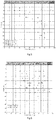
- Figure 5 and figure 6 respectively show measurements performed in one among various test sites the Applicant used to check the performance for the radar 100 object of the invention and through the SPT standard procedure.
- graphs pose relative density of the soil in abscissa and depth of measurement in ordinate.
- Three boreholes were performed in different areas of the test site, and these boreholes are indicated in the annexed figures with markings BH-L-150-1, BH-L-150-1a, BH-L-150-1b. Line measurements between the boreholes were referenced with markings BH-L-150 1/1b, BH-L-150 1a/1b, BH-L-150 1b/1, BH-L-150 1b/1a. Measurements were made in both directions.
- a preferred embodiment of the radar may be configured to provide for transmitting the predetermined radio signal (s1(t)) in such a way that it is swept in frequency between a first lower predetermined frequency f1 and a second higher predetermined frequency f2.
- the signal is swept in frequency according to a predetermined law of frequency variation over the time that may be for instance and in a non-limiting extent a linear law.
- sweeping the signal in frequency may provide for obtaining better measurements, provided that is possible to have a plurality of measurements over the time, in such a way to calculate for a predetermined depth of measurements a plurality of delays of propagation for the predetermined radio signal s1(t) according to different frequencies, and for letting the data processing unit 111 provide for calculating an average between such measurements with the final purpose of providing more reliable data.
- the frequency sweeping may be performed by virtue of a vector analyzer; in this latter case the frequency sweeping is a stepped frequency sweeping.
- a vector analyzer the applicant identified a default number of 1024 analysis points as standard for the stepped sweeping, but this number shall not be intended as limiting for the purpose of the invention.
- the predetermined radio signal s1(t) is numerically or equivalently digitally processed and the receiver 104 may be configured to decompose the received radio signal in a first - in-phase - component (I) and a second - quadrature - component (Q).
- the in-phase component (I) and the quadrature component (Q) are sampled in a plurality of predetermined instants of time for each of which their instantaneous frequency variates in function of the stepped frequency sweep.
- the receiver 104 may be further configured to perform a discrete inverse Fourier transform on each of the in-phase component (I) and quadrature component (Q) producing time-domain samples.
- Delay between the transmission and the moment at which the samples are received allows to calculate or determinate the dielectric constant as above explained, i.e. through the speed or delay in propagation for the predetermined radio signal s1(t).
- Applicant found that numerically processing the signal received by the receiver 104, in particular when also the predetermined radio signal s1(t) is transmitted with numeric processing, proved to be the most robust and effective way of treating the signal in order to achieve precision of measurement.
- the receiver 104 performs the discrete inverse Fourier transform on the in-phase component (I) and quadrature component (Q) of the signal, such a particular solution shall not be considered limitative, provided that the in-phase component (I) and quadrature component (Q) may be fed to the data processing unit 111 in order to let this latter perform the discrete inverse Fourier transform or any other and/or further processing on the received signal.
- the delay of propagation for the predetermined radio signal is calculated by considering the phase delay that the received signal presents with respect to the transmitted predetermined radio signal s1(t).
- the first antenna 101 and the second antenna 102 designed as broadband antennas, in order to efficiently transmit and receive the signal over the entire range of frequencies between the first lower predetermined frequency and the second higher predetermined frequency.
- Dipoles may be used, but it may be preferable to have those dipoles constructed with conical branches, which provide wider bandwidth with respect to traditional cylindrical dipoles.
- the radar 100 may be configured, through the data processing unit 111, to produce a plurality of diagrams, preferably but in a non-limiting extent, produced in a single video screen over the display, or in any case combinable together, including:
- the predetermined radio signal s1(t) may be received by the second antenna 102;
- the data processing unit is technically interchangeable with one or more electronic computers conceived and/or configured for executing portions of software or firmware programs loaded on a non-transitory memory support.
- the software program may be written in any programming language.
- the electronic computers if two or more, may be electronically connected each other by means of a data exchange network and they may share they computation power; the electronic computers of the server subsystem may be therefore arranged in geographically different positions.
- the software or firmware programs may be in the form of a computer program product, stored on a non-transitional memory support, comprising software code portions suitable to be executed by a data processing unit, the software code portions causing the execution of the subsequent steps:
- the data processing unit may be a general purpose processor specifically configured to perform - through the software program - at least part of the steps of the previously described method, or it may be an ASIC or dedicated processor, specifically designed to perform at least part of the steps of the previously described method.
- the non-transitory memory support may be in particular physically internal or external with respect to the server subsystem 101 and or to the processor, and in particular it may be physically divided therefrom, in a form of a "cloud" memory.
- the radar allows obtaining precise data in a substantially real time about the composition, in particular humidity or water amount, of the various layers that compose the soil of the ground.
- the radar and method object of the present invention are not limited to particular depths, provided that any limitation in this sense may be overcome through adoption of a sufficiently long cable for the connection with the antenna.
- the radar of the invention is easily transportable and soil analyses may therefore be performed anywhere.
- the indications provided by the user interface of the radar are user-friendly and easy to read on the display.
- the method of soil analysis exploited by the radar and system of the invention does not require complex pre- or post-processing, and are therefore easy to implement.
Landscapes
- Life Sciences & Earth Sciences (AREA)
- Physics & Mathematics (AREA)
- Engineering & Computer Science (AREA)
- Remote Sensing (AREA)
- Environmental & Geological Engineering (AREA)
- Geology (AREA)
- General Life Sciences & Earth Sciences (AREA)
- General Physics & Mathematics (AREA)
- Geophysics (AREA)
- Electromagnetism (AREA)
- Geophysics And Detection Of Objects (AREA)
- Radar Systems Or Details Thereof (AREA)
Abstract
Description
- The present invention refers to the fields of radar devices and soil analysis; more specifically the invention concerns an electromagnetic soil analysis radar for cross-hole soil analysis. The present invention further refers to a system comprising the electromagnetic soil analysis radar. The present invention further involves an electromagnetic soil analysis method.
- Void ratio and compactness are two of the principal parameters used for geotechnical characterization of soils. Amongst others, they determine the deformation, settlement or liquefaction potential, which in turn might significantly impair the quality as well as the performance of any soil foundation. Direct measurement of the natural void ratio is particularly difficult, since it requires undisturbed samples.
- There are a few methods in order to obtain undisturbed samples directly. Direct available methods are cumbersome and very expensive to perform. Therefore, indirect methods have been developed.
- Among the indirect measurement methods, the SPT - Soil Penetration Test - provides information on soil geotechnical engineering properties, and eventually soil stratigraphy through walled sampling tubes - with a standard size of typically 50.8 mm for the outer diameter and 35 mm for the inner diameter - which penetrate into a borehole; the sampling tube is repeatedly hit by blows of a slide hammer, having a predetermined mass (e.g. 63,5 kg or 140 lb). The sampling tube is driven for a predetermined depth into the borehole (e.g. 150 mm) and the number of blows required to penetrate the predetermined depth is indicative of soil compactness.
- Another indirect measurement method used in this context is the CPT - Cone Penetration Test - which uses a walled tube whose free end is provided with an instrumented conical tip; the tube is pushed - forced to penetrate the soil - at a predetermined, controlled rate (e.g. 1,5 - 2,5 cm/s).
- Such indirect measurement methods have some limitations and often fail, especially with heterogeneous soils also containing coarser materials. Additionally, the interpretation of the results is performed through empirical correlations, and is often affected by relevant uncertainty.
- Furthermore, SPT and CPT methods are suitable to determine punctual compactness of the portions of soil which lie axially, or substantially axially with the penetration direction of the tube, and do not provide reliable indication of portions of soil which, although being just slightly axially spaced from the borehole, may have relevantly different compactness. In other words, SPT and CPT provide a 1-D image of soil compactness.
- The scope of the present invention is therefore to provide an electromagnetic soil analysis device, more specifically a radar, for crosshole soil analysis, in particular for in-situ analysis of soils, which allows to solve the limitations provided by the known indirect measurement methods and furthermore provides the determination of the amount and/or percentages of water and soil in soils filled with water (i.e. saturated soils), in order to allow the user, e.g. the geotechnical engineers, to make estimations about soil compactness.
- The scope of the present invention is also to provide a radar soil analysis system, comprising the ground penetrating radar, for reducing drawbacks associated by the known indirect measurement methods.
- The scope of the present invention is also to provide an electromagnetic soil analysis method which allows solving the drawbacks provided by the known indirect measurement methods.
- According to a first aspect of the invention is disclosed an electromagnetic soil analysis method that comprises:
- a step of making a first borehole (10) in an initial or first predetermined position in the soil (30);
- a step of making a second borehole (20) in a second predetermined position in the soil (30), the second position being different from the first position;
- a step of introducing a first antenna (101) in the first borehole (10) and a second antenna (102) in the second borehole (20);
- a step of feeding a predetermined radio signal to said first antenna (101), so that the first antenna (101) radiates said predetermined radio signal according to a predefined radiation pattern across a portion (31) of said soil (30) so that said predetermined radio signal (s1(t)) may be received by said second antenna (102);
- a step of soil compactness analysis, by determining or calculating the amount of water (xwater ) and/or humidity and/or dielectric constant (ε') of a portion (31) of soil (30) interested by the radiation of the first antenna, said portion (31) of soil (30) being positioned between the first antenna (101) and the second antenna (102),
- wherein the step of determining or calculating the amount of water (xwater ) and/or humidity and/or dielectric constant (ε') of the portion (31) of soil (30) is performed by electronically measuring the speed of propagation of said predetermined radio signal (s1(t)) between said first antenna (101) and said second antenna (102) or the delay with which the predetermined radio signal (s1(t)) transmitted by said first antenna (101) or through a transmitter (103) connected to said first antenna (110) reaches said second antenna (102) or a receiver (104) connected to said second antenna (102).
- According to a further aspect of the invention, the portion (31) of soil (30) is a portion of soil extending, in a direction parallel to a first reference axis X, along an ideal line joining the first antenna (101) to the second antenna (102) and vertically extending, in a direction parallel to a second reference axis Y, for an amount of space including reflection and/or refraction points which are maximally separated from said line joining the first (101) to the second antenna (102) which respectively reflect and/or refract the predetermined radio signal transmitted by the first antenna (101) in such a way that may be detected through the second antenna (102) and/or through the receiver (104) connected to the second antenna (102) beyond a predetermined sensitivity point of said receiver (104).
- According to a further aspect of the invention, the step of soil compactness analysis is a step of crosshole soil compactness analysis between said first borehole (10) and said second borehole (20).
- According to a further aspect, the method comprises the step of moving the first antenna (101) and/or the second antenna (102) in a direction parallel to said first reference axis, and/or moving said first antenna (101) and said second antenna (102) linearly within their respective first borehole (10) and second borehole (20).
- According to a further aspect of the invention, the method comprises moving the first antenna (101) and the second antenna (102) with synchronous motion in their respective first and second boreholes (10; 20).
- In particular, according to a further aspect of the invention, the method comprises moving the first antenna (101) and the second antenna (102) in such a way that during their synchronous motion, the ideal line connecting the first antenna (101) and the second antenna (102) when they are at a respective first and second predetermined depth in their respective first or second hole (10; 20), at a first time of measurement, is parallel to the ideal line connecting the first antenna (101) and the second antenna (102) when they are in at respective third, fourth predetermined depth in their respective first, second hole (10; 20) at a second time of measurement, different from the first time of measurement.
- According to a further aspect, moving the first antenna (101) and/or the second antenna (102) electronically provides and allows the calculation of a 2D or a two-dimensional diagram of the portion (31) of soil (30) under analysis, with the diagram comprising a first and a second coordinate along a first and a second reference axis reciprocally orthogonal, whereby the first coordinate (e.g. X axis) refers to the depth of measurement and a second coordinate (e.g. Y axis) refers to the measured dielectric constant, and/or amount of water or percentage of water, and/or soil composition.
- According to a further aspect of the invention, the first and second predetermined depths respectively held by said first and second antennas (101; 102) at said first time of measurement are substantially placed at a same first depth and the third and fourth predetermined depths respectively held by said first and second antennas (101; 102) at the second time of measurement are substantially placed at a same second depth, the second depth differing from the first depth.
- According to a further aspect of the invention, the step of feeding a predetermined radio signal to said first antenna (101) comprises providing a frequency signal sweeping between a first lower predetermined frequency (f1) and a second higher predetermined frequency (f2) to the first antenna (101).
- According to a further aspect of the invention, said signal is a numeric stepped sweeping signal.
- According to a further aspect of the invention, the method comprises a step of signal processing of a signal received by the receiver (104) or through said second antenna (102); the step of processing producing the extraction of a first in-phase component (I) of said signal, and of a second quadrature component (Q) of said signal, and comprising performing an electronic calculation of a discrete inverse Fourier transform on at least one and preferably both said first in-phase component (I) of said signal and second quadrature component (Q) of said signal for determining said speed of propagation of said predetermined radio signal (s1(t)) or said delay with which the predetermined radio signal (s1(t)) transmitted by said first antenna (101) or through a transmitter (103) connected to said first antenna (110) reaches said second antenna (102) or a receiver (104) connected to said second antenna (102).
- According to a further aspect of the invention, said signal processing and/or said performing of electronic calculation of a discrete inverse Fourier transform are made by said receiver (104).
- According to a further aspect of the invention, said performing of electronic calculation of a discrete inverse Fourier transform is performed by a data processing unit (111) electronically and/or operatively connected to said receiver (104).
- According to a further aspect of the invention, the first lower predetermined frequency (f1) is higher than 50MHz.
- According to a further aspect of the invention, the second upper predetermined frequency (f2) is lower than 1000 MHz.
- According to a further aspect of the invention, the step of determining the amount of water (xwater ) and/or humidity of said portion (31) of soil (30) comprises a step of providing a first electronic datum concerning the dielectric constant of the water (ε'water), a second electronic datum concerning the dielectric constant of the soil (ε'soil ), and a third datum corresponding to a distance (d) between the first antenna (101) and second antenna (102) when in said first borehole (10) and respectively second borehole (20) and/or a distance between the first borehole (10) and the second borehole (20).
- According to a further aspect, the dielectric constant of the soil may range between 3 and 5.
- According to a further aspect of the invention, the step of determining the amount of water (xwater ) and/or humidity in said portion of soil (30) comprises a step of calculating the result of the following formula:

- According to a further aspect of the invention, the step of determining the amount of water (xwater ) is a step of determining the amount of water in water saturated soil or water saturated conditions.
- According to a further aspect of the invention, the step of determining the dielectric constant of the portion (31) of soil (30), is a step of determining the average dielectric constant of the portion of soil and comprises the steps for:
- dividing the distance (d) between the first antenna (101) and second antenna (102) when in said first borehole (10) and respectively second borehole (20) and or a distance between the first borehole (10) and the second borehole (20) by the delay (Δt) with which the predetermined radio signal (s1(t)) transmitted by said first antenna (101) or through a transmitter (103) connected to said first antenna (110) reaches said second antenna (102) or a receiver (104) connected to said second antenna (101), for obtaining a first sub-result;
- dividing, in particular electronic dividing, a number corresponding to the speed of light in vacuum by said first sub-result, obtaining a second sub-result;
- calculating, in particular electronically calculating the power of 2 to said second sub-result, to obtain said dielectric constant of said portion (31) of soil (30).
- According to a further aspect of the invention, the method comprises a step of reversing and/or switching the connection between the first antenna (101) and the second antenna (102) with the transmitter (103) and the receiver (104), said connection determining a first operative configuration, so that the first antenna (101) previously connected to the transmitter (103) results connected to the receiver (104) and so that the second antenna (102) previously connected to the receiver (104) results connected to the transmitter (103), thereby determining a second operative configuration,
said method further comprising a subsequent step of determining or calculating the amount of water (xwater ) and/or humidity and/or dielectric constant (ε') of the portion (31) of soil (30) in said second operative configuration and, optionally, calculating an average and/or difference between the water (xwater ) and/or humidity and/or dielectric constant (ε') of the portion (31) of soil (30) when in said first operative configuration with the amount of water (xwater ) and/or humidity and/or dielectric constant (ε') of the portion (31) of soil (30) when in said second operative configuration. - According to a further aspect of the invention, the step of determining the amount of water (xwater ) and/or humidity of said portion (31) of soil (30) comprises a preventive step of compensation of air humidity and/or calibration, said step comprising setting the first antenna (101) and the second antenna (102) at a distance equal to the distance d of the first to second borehole (10; 20), with only free air between the first and the second antenna (101, 102) and a subsequent step comprising activating the transmitter (103) in order to perform at least one measurement of a dielectric constant (ε') between said first antenna (101) and said second antenna (102).
- According to a further aspect, it is disclosed a computer program product, the computer program product being stored on a non-transitional memory support, comprising software code portions suitable to be executed by a data processing unit, said software code portions causing the execution of the subsequent steps:
- - a step of making a transmitter (103) feed a predetermined radio signal to a first antenna (101), so that the first antenna (101) radiates a predetermined radio signal according to a predefined radiation pattern;
- - a step of setting a receiver (104) connected to a second antenna (102) to receive at least a propagated part of said predetermined radio signal (s1(t)), in particular a part of said predetermined radio signal which has been propagated through a portion (31) of soil (30);
- - a step of determining or calculating the amount of water (xwater ) and/or humidity and/or dielectric constant (ε') of the portion (31) of soil (30) interested by the radiation of the first antenna, said portion (31) of soil (30) being positioned between the first antenna (101) and the second antenna (102),
- - wherein the step of determining or calculating the amount of water (xwater ) and/or humidity and/or dielectric constant (ε') of the portion (31) of soil (30) is performed by electronically measuring the speed of propagation of said predetermined radio signal (s1(t)) between said first antenna (101) and said second antenna (102) or the delay with which the signal transmitted by said first antenna (101) or through a transmitter (103) connected to said first antenna (110) reaches said second antenna (102) or a receiver (104) connected to said second antenna (102).
- According to a further aspect of the invention, the method may comprise the step of calculating an average granulometry of said portion (31) of soil (30) through the measurement of at least said dielectric constant of said portion (31) of soil (30).
- According to a further aspect of the invention, the method may comprise repeatedly performing said step of calculating said average granulometry at a plurality of depths for said first antenna (101) and said second antenna (102); said repeated performance of said step of calculating the average granulometry for the portion (31) of soil (30) producing a profile, in particular an electronic profile of a soil (30) which correlates the average granulometry of the soil (30) with the depth of measurement of the average granulometry.
- According to a further aspect of the invention, the method may comprise storage of a plurality of electronic data concerning an average of a plurality of size values for a set of granules of soil, and electronically processing the electronic data with said dielectric constant for obtaining said average granulometry.
- The invention further discloses an electromagnetic soil analysis device(100) comprising:
- a transmitter (103) configured to transmit a predetermined radio signal (s1(t)) and configured to be connected - in use - with a first antenna (101);
- a receiver (104) configured to receive at least a part of said predetermined radio signal (s1(t)) after a propagation into a portion (31) of soil (30) and configured to be connected - in use - with a second antenna (102), and
- a data processing unit (111) configured to calculate an amount of water (xwater ) and/or humidity and/or dielectric constant (ε') of the portion (31) of soil (30) by automatically and electronically calculating the speed of propagation of said predetermined radio signal (s1(t)) between said transmitter (103) and said receiver (104) or by calculating the delay with which the predetermined radio signal (s1(t)) transmitted by said transmitter (103) reaches said second antenna (102) or a receiver (104) connected to said second antenna (102).
- According to a further aspect, said device is a radar, in particular a cross-hole soil analysis radar.
- According to a further aspect of the invention, the predetermined radio signal (s1(t)) is a signal sweeping between a first lower predetermined frequency (f1) and a second higher predetermined frequency (f2).
- According to a further aspect of the invention, the first lower predetermined frequency (f1) is higher than 50MHz.
- According to a further aspect of the invention, the second upper predetermined frequency (f2) is lower than 1000 MHZ.
- According to a further aspect of the invention, the transmitter (103) is configured for transmitting said predetermined radio signal (s1(t)) as a signal sweeping in frequency, between a first lower predetermined frequency (f1) and a second higher predetermined frequency (f2).
- According to a further aspect of the invention, said sweeping follows a predetermined law of frequency variation over time.
- According to a further aspect of the invention, the device (100), optionally the data processing unit (111), is configured for:
- loading a first electronic datum concerning the dielectric constant of the water (ε'water ) and a second electronic datum concerning the dielectric constant of the soil (ε'soil ), and a third datum corresponding to a distance (d) between the first antenna (101) and second antenna (102),
- calculating the amount of water (xwater ) according to the following formula:

- According to a further aspect of the invention, the receiver (104) comprises a vector analyzer configured for, or is configured for, electronically decomposing the received signal in a first - in-phase - component (I) and a second - quadrature - component (Q) and/or providing on its output a first - in-phase - component (I) and a second - quadrature - component (Q).
- According to a further aspect of the invention, the receiver (104) is configured for performing sampling of the received signal in a plurality of predetermined instants of time, for producing sampled versions of said first - in-phase - component (I) and a second - quadrature - component (Q).
- According to a further aspect of the invention, the receiver (104) and/or the data processing unit (111) are configured for performing a discrete inverse Fourier transform on at least a part of the signal received by said receiver (104) or received through said second antenna (103), said discrete inverse Fourier transform producing in output samples in the time domain for electronically calculating the speed of propagation of said predetermined radio signal (s1(t)) between said transmitter (103) and said receiver (104) or for calculating the delay with which the predetermined radio signal (s1(t)) transmitted by said transmitter (103) reaches said second antenna (102) or said receiver (104) connected to said second antenna (102)
- According to a further aspect of the invention, the device (100), in particular the data processing unit (111) is configured to electronically calculate the dielectric constant of the portion (31) of soil (30) by:
- dividing a first electronic datum corresponding to the distance (d) between the first antenna (101) and second antenna (102) when in said first borehole (10) and respectively second borehole (20) and or a distance between the first borehole (10) and the second borehole (20) by the delay (Δt) with which the predetermined radio signal (s1(t)) transmitted by said first antenna (101) or through a transmitter (103) connected to said first antenna (110) reaches said second antenna (102) or a receiver (104) connected to said second antenna (101), for obtaining a first sub-result;
- dividing, in particular electronic dividing, a number corresponding to the speed of light in vacuum by said first sub-result, obtaining a second sub-result;
- calculating, in particular electronically calculating the power of 2 to said second sub-result, to obtain said dielectric constant of said portion (31) of soil (30).
- According to a further aspect of the present invention a radar soil analysis system (200) is disclosed, said system (200) comprising an electromagnetic soil analysis device (100) according to one or more of the aspects of the invention and:
- a first antenna (101), electrically connected to said transmitter (103); and
- a second antenna (102), electrically connected to said receiver (104).
- According to a further aspect of the invention, the first and/or second antenna (101, 102) are dipole antennas.
- According to a further aspect of the invention, the first and/or second antenna (101, 102) are broadband antennas, optionally dipole broadband antennas, optionally conical and/or biconical dipole antennas.
- According to a further aspect of the invention, the first antenna (101) and the second antenna (102) are of the same type and/or with the same size.
- According to a further aspect of the invention, the broadband antennas have a bandwidth greater than 100 MHz, preferably greater than 200 MHz, more preferably greater than 300 MHz.
- According to a further aspect of the invention, the first antenna (101) and the second antenna (102) have an almost constant radiation pattern along at least one radiation plane, in particular the H-Plane, and/or have a radiation gain/attenuation as a function of an angle of observation over at least one radiation plane, in particular the H-Plane, which is substantially constant.
- In the subsequent detailed description at least one preferred and non-limiting embodiment of the invention will be presented, and described with reference to the annexed figures wherein:
-
Figure 1 shows a schematic view of an electromagnetic soil analysis device according to the invention. -
Figure 2 shows a schematic view of a radar soil analysis system according to the invention. -
Figure 3 shows a graph indicating the variation of the dielectric constant ε' soil of four predetermined types of soils according to different grain sizes from 0 to 4mm and from 8mm to 16mm (four curves) as a function of the water content. -
Figure 4 reports the maximum reachable distance as a function of the frequency for a radar configuration according to the invention. -
Figure 5 and figure 6 respectively show measurements performed in a test site by the radar object of the invention and through the SPT standard procedure. -
Figure 7 shows a graph identifying a composition of the soil in a test site as a function of the depth of analysis. -
Figure 8 shows a graph identifying average granulometry and average dielectric constant of the soil in the same test site where the composition offigure 7 was measured, as a function of the depth of analysis, as measured through the radar object of the present invention. -
Figure 9 shows an example of a screenshot of an exemplary embodiment showing the data that may be produced by the radar object of the invention. -
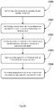
Figure 10 shows a brief flow diagram of a method according to the invention. - An electromagnetic soil analysis device is referenced under
number 100, in particular a radar and more specifically a cross-hole soil analysis radar. Theradar 100 is conceived and specifically configured for letting a user perform an analysis of soils, in particular for determining the amount of humidity of a portion of soil and/or percentage of water in a portion of soil, primarily when the soil is saturated with water. - The
radar 100 comprises a RF board, provided with at least onetransmitter 103 and onereceiver 104; thetransmitter 103 is configured to transmit a predetermined signal s1(t) which is a radio signal lying in a predetermined band, i.e. comprised between a first minimum frequency and a second maximum frequency; thereceiver 104 is configured to receive radio signals, in particular in the band wherein thetransmitter 103 transmits. Theradar 100 further comprises apower management unit 105, electrically connected at least to thereceiver 104 and to thetransmitter 103 for feeding them electrical energy required to operate. - Although the
radar 100 may operate only through connection to a net power source, in a preferred embodiment shown infigure 1 , theradar 100 is provided with abattery 106, electrically connected to thepower management unit 105, and to amains input 107, electrically connected directly to thepower management unit 105. This also allows operation in environments where electrical power coming from the net may not be present, and gives flexibility of operation, especially on the field.Battery 106 may be charged from the net power surge, through a connection with themains input 107. Thepower management unit 105 may be configured to provide a conversion from the standard net voltage (e.g. 220-240V /110-120V AC, 50/60Hz) to a direct current powering signal, whose voltage may depend on the type and rated voltage of the battery which is actually used. Furthermore,power management unit 105 may be configured to perform lowering of voltage, e.g. to 12 Vdc and/or to prevent excessive recharging of thebattery 106, to prevent accidental inversion of polarity of thebattery 106 or to prevent peaks of signal power directly arriving to thetransmitter 103 or to thereceiver 104. - The
radar 100 preferably comprises anamplification stage 108, which infigure 1 is electrically connected to the RF board; theamplification stage 108 may typically comprise a power RF amplifier for thetransmitter 103 and a low-noise RF amplifier for thereceiver 104, and may be provided, if so required by the specific design of the device, by an RF circulator. In any case, the applicant suggests that thetransmitter 103 may integrate a built-in RF power amplifier and/or the receiver may integrate a built-in low noise RF pre-amplifier. - The
transmitter 103 and thereceiver 104 are respectively connected to afirst RF output 109 and to asecond RF input 110. In the embodiment shown infigure 1 , this connection is indirect, and the direct connection with RF output and RF input is provided by theamplification stage 108. In the actual realization, the RF output and RF input may be provided with standard RF plug or sockets like, preferably and in a non-limiting extent, N-type connectors or any other type of RF connector which may be suitable for the application. Preferably, the first RF output and the second RF input are physically separated. Such a physical separation may be convenient provided that, as it will be better described in the subsequent portion, theradar 100 may be connected in use to separate antennas which shall be placed in separated boreholes. - The
radar 100 may further comprise adata processing unit 111, electrically connected to the RF board and fed through thepower management unit 105; thedata processing unit 111 may be configured to manage and control operative parameters of thetransmitter 103 and of thereceiver 104, and may be further configured to process the signal received from thereceiver 104 in order to provide data suitable to better characterize the soil under examination. Furthermore, theradar 100 may comprise a data I/O port, e.g. aUSB port 114, which is electrically connected to thedata processing unit 111, with the purpose of rendering data provided thereby available to other computers or electronic units. - Optionally, albeit preferably, the
radar 100 may comprise user interfaces like, e.g., adisplay 112 and akeyboard 113. All the devices previously cited may be integrated in a box, e.g. a waterproof box, and may be conceived for being suitable to operate in the field, e.g. they may have appropriate IPxx protection against dust and water. - Optionally, albeit preferably, the
radar 100 may comprise a wireless interface, for example a Wi-Fi, or WiMax interface, that may integrate a protected or ciphered communication protocol; thewireless interface 115 is electrically connected at least with thedata processing unit 111.Wireless interface 115 is configured to let theradar 110 be remotely controlled, e.g. at least remotely activated or deactivated and/or to switch on/off or to remotely control some parameters of thetransmitter 103. Wireless interface may be arranged at a frequency and/or radio band significantly differing from the frequencies used for the signal injected in the first antenna (101), since in such a way it may be possible to prevent interferences with the measurements. - Although not being represented in the schematic diagram of
figure1 , to thedata processing unit 111 may be electrically connected a memory which may be used to store data important to actually make theradar 100 operate, i.e. operative parameters for thetransmitter 103 and/or for thereceiver 104, as well as other data as an operative system to make the radar operate stand-alone. -
Figure 2 shows a soil analysis radar system, which comprises theradar 100 as previously described. The soil analysis radar system further comprises afirst antenna 101 and a second antenna 102: thefirst antenna 101 is in use detachably connected to theRF output 109 and thesecond antenna 102 is detachably connected to theRF input 110. Afirst cable 117 of appropriate length connects thefirst antenna 101 to theRF output 109 and asecond cable 117 of appropriate length connects thesecond antenna 102 to theRF input 110.Cables 117 are standard RF cables which the technician may choose for the particular frequency of the signal generated by the radar.Cables 117 may for example be RG58, RG8, H155, RG213, or other type of coaxial cables. - The applicant performed several studies about which type of antenna may be used for this specific application, selecting between dipoles, monopoles, loop, spiral, fractal, biconical and combinations of spirals and dipoles. Other types of antennas were discarded provided that in any case the antenna may be slanted since the boreholes have a relatively small diameter, typically about 70mm.
- Preferably but in a non-limiting extent, the first and the second antenna may be of the same type, and in particular at least one of them may be a dipole antenna, in particular a center-fed dipole antenna, whose branches may be realized through conical or truncated conical sticks fed in correspondence of their vertexes or in correspondence of their smallest base. Such an antenna resulted having a bandwidth of some hundreds of MHz, suitable to be used for the predetermined radio signal s1(t) also in case it is swept in frequency. Preferably, but in a non-limiting extent, the required bandwidth for the antenna may be greater than 100 MHz, preferably greater than 200 MHz, and even more preferably greater than 300 MHz.
- Moreover, using a dipole ensures minimum affection of measurement if the antenna is rotated along it axis of maximum development, provided that the radiation pattern of such a dipole presented an almost constant value of gain over the entire 360° azimuth of the H-plane. Furthermore, relatively large HPBW angle over E-plane further allows for having minimum affection of measurements in case the antenna is slightly misaligned with respect to the borehole axis.
- In order to make the antennas suitable to operate in an hostile environment like the soil, especially since antennas operate in an environment characterized by presence of water or humidity, the first and the second antenna are provided with a
waterproof case 116. In order to prevent or reduce as much as possible interference with the propagating radio waves respectively sent and received by the antennas, thewaterproof case 116 may be preferably made in plastics, e.g. PVC. In a test performed by the applicant, thewaterproof case 116 was 600mm long and 60mm wide. In any case, in order to let thewaterproof case 116 pass within the boreholes, the minimum diameter of the borehole shall be greater than the maximum diameter of thewaterproof case 116. In any case, relevant margin between the minimum diameter of the borehole and the maximum diameter of thewaterproof case 116 should be kept in order to avoid any risk of having the case stuck in the borehole. Applicant performed tests on the antenna in direct contact with water, and with awaterproof case 116 filled with air, and discovered that water affects the antenna gain in function of the frequency; therefore, having awaterproof case 116 may allow obtaining a significantly more precise measurement. - The first and the
second antenna -
Figure 2 further depicts the typical installation of the system 200 in the field, wherein thefirst antenna 101 and thesecond antenna 102 are arranged with theirwaterproof cases 116 introduced in a respectivefirst borehole 10 andsecond borehole 20 pre-emptively practiced in the soil. Preferablysuch boreholes second borehole second antennas - The
radar 100 provides information about the humidity of the ground where soil under exam is not characterized by the presence of groundwater or aquifers, or about the percentage of water of the soil when in presence of groundwater or aquifers. - The concept exploited by the
radar 100 is based on propagation of electromagnetic radio waves, which is affected by the dielectric constant, in particular the average dielectric constant, of the portion of soil interested by the propagation of the radio waves. The dielectric constant is directly related to the humidity (when in partially saturated conditions) or water content (in saturated conditions) of the interested portion of soil. In particular, when dealing with water saturated soil, void ratio can be directly obtained. - The average dielectric constant mainly depends on the volumetric ratio between water and soil particles. Dielectric constant of the water is about 30 times greater than the dielectric constant of the soil particles, and the content of water or humidity in a portion of soil may be determined in good approximation by evaluating the measured propagation speed v [m/s] of the electromagnetic radio waves which is related to the dielectric constant by the following equation, given c as light speed in vacuum and ε as the dielectric constant:

- Actual radio wave propagation speed is further affected by various delays which are caused by cables, antennas and air. In the context of the present invention, their influence is not taken into account since their influence may be measured or anyway determined and therefore compensated.
- Dry soil may be provided with its own dielectric constant, herewith referred as ε'soil (typically, albeit non-limiting, ranging between ≈ 3÷5), and is determined before the performance of the analysis and stored by means of known techniques in the memory of the
radar 100 in order to be deciphered by thedata processing unit 111 as a predetermined datum. The dielectric constant of the water ε'water is typically also known, and is ≈ 80. The dielectric constant of the water e'water is stored by means of known techniques in the memory of theradar 100 in order to appear to thedata processing unit 111 as a predetermined datum, together with ε'soil. - When a predetermined portion of soil is analyzed, it can be inferred that in a predetermined distance d, e.g. up to 10m or even 20m, when in presence of groundwater or aquifers, a first part xwater of this distance d is actually a void filled by water (100%), while a second, and resting, part xsoil is actually soil. The first and the second part are, in principle, the unknown variables to be determined.
- Since the
radar 100 directly measures time Δt the radiowaves need to travel for the distance d, i.e. the time required for the first predetermined signal s1(t) to travel from thefirst antenna 101 to thesecond antenna 102 or (with compensation) the time required to travel from thetransmitter 103 to thereceiver 104, and so determines the speed

portion 31 ofsoil 30 given by:
- The first and the second part xwater, xsoil of the distance, and therefore the amount of water in a predetermined portion of soil are calculated through the following equations:


-
Figure 3 shows a graph indicating the variation of the dielectric constant ε' soil of four predetermined types of soils according to different grain sizes from 0 to 4mm and from 8mm to 16mm (four curves) as a function of the water content. In particular,figure 3 is exemplificative and shall not be interpreted in a limiting extent. Heterogeneous types of soils are characterized, when dry (0% of water or humidity) by a dielectric constant ε' soil which for the purposes of the present invention may be considered almost constant: among the various types of soils which Applicant kept in consideration, when dry, ε' soil ranges substantially between [1,9 - 2,9] and therefore may be considered, for the purposes of the operation of the radar according to the invention, as a constant, because even if with small amounts of water (<8%) ε' soil gets at least 2-3 times greater for any type of soil. - This means that the dielectric constant of the soil ε' soil when dry may be set as default data (e.g. ε' soil = 2.2) in the memory, and correction may be made by the user in order to force the
data processing unit 111 perform the above calculations according to a value dielectric constant of the soil which is different by the default value, in order to obtain more precise indications of the amount of water or humidity of the analyzed soil. - In general terms, the operation of the
radar 100 and system 200 is performed according to the following steps: - a step of making a
first hole 10 in a first predetermined position in theground 30; - a step of making a
second hole 20 in a second predetermined position in theground 30, the second position being different from the first position; - a step of introducing a
first antenna 101 in the first borehole and asecond antenna 102 in the second borehole; - a step of feeding a predetermined radio signal to the
first antenna 101, so that thefirst antenna 101 radiates the predetermined radio signal s1(t) according to a predefined radiation pattern; - a step of determining the percentage and/or amount of water xwater and/or humidity and/or the dielectric constant ε' of a
portion 31 ofsoil 30 interested by the radiation of the first antenna, the portion of soil being positioned between thefirst antenna 101 and thesecond antenna 102. - More specifically, the determination of the percentage and/or amount of water and/or humidity of the
portion 31 ofsoil 30, is electronically performed through thedata processing unit 111, which is configured to: - activate the
transmitter 103 in order to make it send to thefirst antenna 101 the predetermined radio signal s1(t); - analyze the signal received by the
receiver 104 through thesecond antenna 102; - calculating the time which lapses between the transmission of the predetermined signal s1(t) and the receipt of the predetermined radio signal s1(t);
- then, retrieving from the memory the distance d as a known datum; and retrieving from the memory the dielectric constant of the soil ε'soil, and to
- extrapolate the amount of distance which is in average covered by water, or void, or extrapolate the humidity of the soil by performing the calculation according to equation (3).
- According to an important procedural aspect, before starting the measurement in the soils, a step of calibration of the
radar 100 should be made by setting thefirst antenna 101 and thesecond antenna 102 at a distance equal to the distance d of the first to second borehole, with only free air between theantennas transmitter 103 is activated in order to perform a single measurement. Then the antennas may be introduced in theboreholes data processing unit 111 may automatically electronically compensate the humidity and dielectric constant of the air from the dielectric constant of the soil. - According to a specific and non-limiting embodiment of the invention, the
data processing unit 111 may be configured to electronically calculate the percentage of water, in particular the average percentage of water in the selected portion of soil, by further calculating at least the first and eventually the second of the two subsequent equations:

- During the operation of the
radar 100, thefirst antenna 101 and thesecond antenna 102 may be moved through the first andsecond boreholes - In particular, the
portion 31 ofsoil 30 is a portion of soil extending, in a direction parallel to a first reference axis X, along an ideal line joining thefirst antenna 101 to thesecond antenna 102 and vertically extending, in a direction parallel to a second reference axis Y, for an amount of space including reflection and/or refraction points which are maximally separated from the line joining the first 101 to thesecond antenna 102 which respectively reflect and/or refract the predetermined radio signal transmitted by thefirst antenna 101 in such a way that may be detected through thesecond antenna 102 and/or through the receiver connected to thesecond antenna 102 beyond a predetermined sensitivity point of the receiver. - In a preferred and non-limiting process of soil analysis, the first and the
second antenna second boreholes radar 100 and system 200 includes therefore the steps of moving thefirst antenna 101 and thesecond antenna 102 in such a way so that during their synchronous motion, the ideal line connecting thefirst antenna 101 and thesecond antenna 102 when they are in at a respective first and second predetermined depth in their respectivefirst borehole 10 andsecond borehole 20 at a first time of measurement, is parallel to the ideal line connecting thefirst antenna 101 and thesecond antenna 102 when they are in at respective third, fourth predetermined depth in their respectivefirst borehole 10 andsecond borehole 20 at a second time of measurement different from the first time of measurement. Slices of soils are therefore inclined with respect to the horizontal direction, and such a way of analyzing the soil may be proper when dealing with groundwater or aquifers relevantly inclined and having different depths in correspondence of the first and second boreholes, or when measurements are made in correspondence of soils which are known to have a plurality of inclined layers. - If, in a more particular way of analyzing the ground, the user wishes to analyze horizontal slices of soil at different depths, the
first antenna 101 and thesecond antenna 102 are moved in their respectivefirst borehole 10 andsecond borehole 20 in such a way to keep a same depth from the ground level. In this particular case, the first and second predetermined depths respectively held by the first andsecond antenna 101; 102 at the first time of measurement are substantially placed at a same first depth and the third and fourth predetermined depths respectively held by the first andsecond antenna 101; 102 at the second time of measurement are substantially placed at a same second depth, the second depth differing from the first depth. - The motion of the first and
second antenna present radar 100 is actually conceived.Figure 4 reports a graph of frequencies which Applicant considered the most effective for the specific purpose to which theradar 100 is actually conceived. In particular graph offigure 4 reports the maximum reachable distance as a function of the frequency for a radar configuration wherein the predetermined radio signal s1(t) is injected in the cable with a power of OdBm. The cables have a lengths of 30m each, such a length corresponding to the maximum depth of each of the first andsecond boreholes figure 5 , allowable zones are those which the received signal power was >80dBm while those which are not allowable are those wherein the received signal power was <80dBm. - From
figure 5 and independently from the sensitivity of thereceiver 104, it results that the curve delimiting the allowable zone from the non-allowable zone is inversely proportional with respect to increasing frequency, in a range between 50-1000 MHz, which is the range that preferably should be used to operate the radar. -
Figure 6 further shows how distance d between thefirst borehole 10 and thesecond borehole 20 affects the measurement of the signal attenuation. Measurements were taken keeping constant the power of the transmitted predetermined signal. Measurement were taken at distances d of [5; 10; 15] m. For frequencies up to 250 MHz, it resulted that increasing 5m in the distance d produces an average increase of attenuation of about 20 dB. - The average dielectric constant of the soil is further affected by the soil granulometry, i.e. size distribution in a collection of grains.
Figure 7 depicts actual soil composition for a site test, as a function of the depth of analysis, with distinction of clay, slit, sand, gravel and stones.Figure 8 shows the average dielectric constant measured in the same site test, and average granulometry calculated through theradar 100. - The applicant provided for a classification of clay, silt, sand, gravel and stones according to an average size of grains: clay about 1.5 µm, silt about 8 µm, sand about 0.8mm, gravel about 16mm and stones about 60mm. Average granulometry g may be calculated as a function of the following equation that keeps into account the previously cited average sizes of grains:

- Through the measurements provided in
figure 8 , obtained in controlled conditions, it has been possible to quantify the accuracy of the radar. It has been shown that the water content can be determined with a precision of about 5%. - Therefore, the Applicant provided for a specific configuration for the
radar 100, which in a particular and non-limiting embodiment may store a plurality of size values for a set of granules of thesoil 30, and the data processing unit may be configured to calculate the average granulometry of the soil, according to the above equation, through the measurement of the average dielectric constant of the soil. The step of calculating the average size of grains, may be repeated at different depths, through the procedure of motion of thefirst antenna 101 andsecond antenna 102 in their respective first,second boreholes - The applicant underlines that the attenuation provided by the soil, the dielectric constant of the soil and the delay of propagation of the predetermined radio signal s1 (t) are independent from the direction of measurement, i.e. should result the same if the
first antenna 101 andsecond antenna 102 are switched in their connection with theRF output 109 andRF input 110. A further optional step may include switching the connection of thefirst antenna 101 from theRF output 109 to RF input 110 and switching the connection of thesecond antenna 102 from theRF input 110 to theRF output 109 in order to perform the measurement for a second time keeping the depth constant. If a value of measured dielectric constant ε' is obtained, i.e. another value of % water, % soil, xsoil, %xwater is obtained, the outputted measurement may be or may further include an average of the previously obtained values. - Through the motion of the
first antenna 101 and thesecond antenna 102 it is possible to obtain a 2D, i.e. a two-dimensional diagram of the portion of soil under analysis, comprising a first and a second coordinate along a first and a second reference axis reciprocally orthogonal, wherein the first coordinate (e.g. X axis) refers to the depth of measurement and a second coordinate (e.g. Y axis) refers to the measured dielectric constant, and/or amount of water or percentage of water, and/or soil composition. -
Figure 5 and figure 6 respectively show measurements performed in one among various test sites the Applicant used to check the performance for theradar 100 object of the invention and through the SPT standard procedure. In particular, graphs pose relative density of the soil in abscissa and depth of measurement in ordinate. Three boreholes were performed in different areas of the test site, and these boreholes are indicated in the annexed figures with markings BH-L-150-1, BH-L-150-1a, BH-L-150-1b. Line measurements between the boreholes were referenced with markings BH-L-150 1/1b, BH-L-150 1a/1b, BH-L-150 1b/1, BH-L-150 1b/1a. Measurements were made in both directions. The two diagrams, yet at a glance, show that measurements performed through the technique according to the invention provide significantly less scattering, and a more accurate insight into the relative density distribution with depth. The upper 10m to 15 m are generally loos to medium dense, while, as expected, the compactness of the soil increases with depth. Locally noticeable decreases are due to the presence of material with significantly greater average size. In particular, in the test site the rather high density observed between 3m and 4m can be explained by presence of a very finely grained lacustrine deposits. These findings are in line with the information extracted and derived from the core boxes. - A preferred embodiment of the radar may be configured to provide for transmitting the predetermined radio signal (s1(t)) in such a way that it is swept in frequency between a first lower predetermined frequency f1 and a second higher predetermined frequency f2. The signal is swept in frequency according to a predetermined law of frequency variation over the time that may be for instance and in a non-limiting extent a linear law. Applicant found that sweeping the signal in frequency may provide for obtaining better measurements, provided that is possible to have a plurality of measurements over the time, in such a way to calculate for a predetermined depth of measurements a plurality of delays of propagation for the predetermined radio signal s1(t) according to different frequencies, and for letting the
data processing unit 111 provide for calculating an average between such measurements with the final purpose of providing more reliable data. - In particular, the frequency sweeping may be performed by virtue of a vector analyzer; in this latter case the frequency sweeping is a stepped frequency sweeping. When using a vector analyzer the applicant identified a default number of 1024 analysis points as standard for the stepped sweeping, but this number shall not be intended as limiting for the purpose of the invention.
- Preferably but in a non-limiting extent, the predetermined radio signal s1(t) is numerically or equivalently digitally processed and the
receiver 104 may be configured to decompose the received radio signal in a first - in-phase - component (I) and a second - quadrature - component (Q). The in-phase component (I) and the quadrature component (Q) are sampled in a plurality of predetermined instants of time for each of which their instantaneous frequency variates in function of the stepped frequency sweep. Thereceiver 104 may be further configured to perform a discrete inverse Fourier transform on each of the in-phase component (I) and quadrature component (Q) producing time-domain samples. Delay between the transmission and the moment at which the samples are received allows to calculate or determinate the dielectric constant as above explained, i.e. through the speed or delay in propagation for the predetermined radio signal s1(t). Applicant found that numerically processing the signal received by thereceiver 104, in particular when also the predetermined radio signal s1(t) is transmitted with numeric processing, proved to be the most robust and effective way of treating the signal in order to achieve precision of measurement. - Albeit it has been indicated that the
receiver 104 performs the discrete inverse Fourier transform on the in-phase component (I) and quadrature component (Q) of the signal, such a particular solution shall not be considered limitative, provided that the in-phase component (I) and quadrature component (Q) may be fed to thedata processing unit 111 in order to let this latter perform the discrete inverse Fourier transform or any other and/or further processing on the received signal. - Otherwise, according to another non-limiting alternative, the delay of propagation for the predetermined radio signal is calculated by considering the phase delay that the received signal presents with respect to the transmitted predetermined radio signal s1(t).
- In such a configuration, it may be preferable to have the
first antenna 101 and thesecond antenna 102 designed as broadband antennas, in order to efficiently transmit and receive the signal over the entire range of frequencies between the first lower predetermined frequency and the second higher predetermined frequency. Dipoles may be used, but it may be preferable to have those dipoles constructed with conical branches, which provide wider bandwidth with respect to traditional cylindrical dipoles. - A typical report provided through the display of the
radar 100 is shown infigure 9 . Advantageously, in order to let the user have full and immediate analysis of the engineering features of the soil under analysis, theradar 100 may be configured, through thedata processing unit 111, to produce a plurality of diagrams, preferably but in a non-limiting extent, produced in a single video screen over the display, or in any case combinable together, including: - a
first graph 1001 correlating the dielectric constant measured for a plurality of depth of analysis forportions 31 ofsoils 30 each one arranged at a predetermined depth from the ground with the depth at which the analyzedportion 31 lies; - a
second graph 1002 correlating the amount and/or percentage of water and soil in apredetermined portion 31 ofsoil 30 with the depth at which the analyzedportion 31 lies; - a
third graph 1003 correlating the delay of reception - by thesecond antenna 102 and/or the receiver 104 - of the predetermined radio signal s1(t) transmitted by or through thefirst antenna 102 and/or thetransmitter 103; - a
fourth graph 1004, correlating the amplitude of the signal received - by thesecond antenna 102 and/or thereceiver 104 with the frequency of the signal. - Resuming, through the radar object of the invention the following method of soil analysis may be performed (see also
figure 10 ): - a step (block 2000) for making a
first borehole 10 in a first predetermined position in thesoil 30; - a step (block 2001) for making a
second borehole 20 in a second predetermined position in thesoil 30, the second position being different from the first position; - a step (block 2002) for introducing a
first antenna 101 in thefirst borehole 10 and asecond antenna 102 in thesecond borehole 20; - a step (block 2003) for feeding a predetermined radio signal to the
first antenna 101, so that thefirst antenna 101 radiates the predetermined radio signal according - to a predefined radiation pattern across a
portion 31 of thesoil 30, so that the predetermined radio signal s1(t) may be received by thesecond antenna 102; - a step (block 2004) for determining or calculating the amount of water (xwater ) and/or humidity and/or dielectric constant ε' of a
portion 31 ofsoil 30 interested by the radiation of the first antenna, theportion 31 ofsoil 30 being positioned between thefirst antenna 101 and thesecond antenna 102, - wherein the step of determining or calculating the amount of water (xwater ) and/or humidity and/or dielectric constant ε' of the
portion 31 ofsoil 30 is performed by electronically measuring the speed of propagation of the predetermined radio signal s1(t) between thefirst antenna 101 and thesecond antenna 102 or the delay with which the predetermined radio signal s1(t) transmitted by thefirst antenna 101 or through atransmitter 103 connected to thefirst antenna 110 reaches thesecond antenna 102 or areceiver 104 connected to thesecond antenna 102. - It may be understood that the data processing unit is technically interchangeable with one or more electronic computers conceived and/or configured for executing portions of software or firmware programs loaded on a non-transitory memory support. The software program may be written in any programming language. The electronic computers, if two or more, may be electronically connected each other by means of a data exchange network and they may share they computation power; the electronic computers of the server subsystem may be therefore arranged in geographically different positions.
- In particular, the software or firmware programs may be in the form of a computer program product, stored on a non-transitional memory support, comprising software code portions suitable to be executed by a data processing unit, the software code portions causing the execution of the subsequent steps:
- a step of making a
transmitter 103 feed a predetermined radio signal to afirst antenna 101, so that thefirst antenna 101 radiates a predetermined radio signal according to a predefined radiation pattern; - a step of setting a
receiver 104 connected to asecond antenna 102 to receive at least a propagated part of the predetermined radio signal (s1(t)), in particular a part of the predetermined radio signal which has been propagated through aportion 31 ofsoil 30; - a step of determining or calculating the amount of water xwater and/or humidity and/or dielectric constant ε' of the
portion 31 ofsoil 30 interested by the radiation of the first antenna, theportion 31 ofsoil 30 being positioned between thefirst antenna 101 and thesecond antenna 102, - wherein the step of determining or calculating the amount of water (xwater and/or humidity and/or dielectric constant ε' of the
portion 31 ofsoil 30 is performed by electronically measuring the speed of propagation of the predetermined radio signal s1(t) between thefirst antenna 101 and thesecond antenna 102 or the delay with which the signal transmitted by thefirst antenna 101 or through atransmitter 103 connected to thefirst antenna 110 reaches thesecond antenna 102 or areceiver 104 connected to thesecond antenna 102. - The data processing unit may be a general purpose processor specifically configured to perform - through the software program - at least part of the steps of the previously described method, or it may be an ASIC or dedicated processor, specifically designed to perform at least part of the steps of the previously described method.
- The non-transitory memory support may be in particular physically internal or external with respect to the
server subsystem 101 and or to the processor, and in particular it may be physically divided therefrom, in a form of a "cloud" memory. - The advantages of the radar and the method object of the present invention are clear from the above description. In particular, the radar allows obtaining precise data in a substantially real time about the composition, in particular humidity or water amount, of the various layers that compose the soil of the ground. The radar and method object of the present invention are not limited to particular depths, provided that any limitation in this sense may be overcome through adoption of a sufficiently long cable for the connection with the antenna. Through the radar system and method previously disclosed it is possible to obtain two-dimensional diagrams of the soil composition in a very cost effective and time saving way. The radar of the invention is easily transportable and soil analyses may therefore be performed anywhere. The indications provided by the user interface of the radar are user-friendly and easy to read on the display. The method of soil analysis exploited by the radar and system of the invention does not require complex pre- or post-processing, and are therefore easy to implement.
- It is finally clear that adaptations or variations can be brought to the present invention that would be obvious for a person skilled in the art, without departing from the scope of protection provided by the annexed claims.
Claims (15)
- Electromagnetic soil analysis method, the method being characterized in that it comprises:- a step of making a first borehole (10) in an initial or first predetermined position in the soil (30);- a step of making a second borehole (20) in a second predetermined position in the soil (30), said second position being different from the first position;- a step of introducing a first antenna (101) in the first borehole (10) and a second antenna (102) in the second borehole (20);- a step of feeding a predetermined radio signal (s1(t)) to said first antenna (101), so that the first antenna (101) radiates said predetermined radio signal according to a predefined radiation pattern across a portion (31) of said soil (30) so that said predetermined radio signal (s1(t)) may be received by said second antenna (102);- a step of soil compactness analysis, by determining or calculating the amount of water (xwater ) and/or humidity and/or dielectric constant (ε') of a portion (31) of soil (30) interested by the radiation of the first antenna, said portion (31) of soil (30) being positioned between the first antenna (101) and the second antenna (102),- wherein the step of determining or calculating the amount of water (xwater ) and/or humidity and/or dielectric constant (ε') of the portion (31) of soil (30) is performed by electronically measuring the speed of propagation of said predetermined radio signal (s1(t)) between said first antenna (101) and said second antenna (102) or the delay with which the predetermined radio signal (s1(t))transmitted by said first antenna (101) or through a transmitter (103) connected to said first antenna (110) reaches said second antenna (102) or a receiver (104) connected to said second antenna (102).
- A method according to claim 1, wherein the portion (31) of soil (30) is a portion of soil extending, in a direction parallel to a first reference axis X, along an ideal line joining the first antenna (101) to the second antenna (102) and vertically extending, in a direction parallel to a second reference axis Y, for an amount of space including reflection and/or refraction points which are maximally separated from said line joining the first (101) to the second antenna (102) which respectively reflect and/or refract the predetermined radio signal transmitted by the first antenna (101) in such a way that may be detected through the second antenna (102) and/or through the receiver (104) connected to the second antenna (102) beyond a predetermined sensitivity point of said receiver (104).
- A method according to claim 1 or 2, comprising the steps of moving the first antenna (101) and the second antenna (102) with synchronous motion in their respective first and second boreholes (10; 20) in such a way that during their synchronous motion the ideal line connecting the first antenna (101) and the second antenna (102), when they are in at a respective first and second predetermined depth in their respective first or second hole (10; 20) at a first time of measurement, is parallel to the ideal line connecting the first antenna (101) and the second antenna (102) when they are in at respective third, fourth predetermined depth in their respective first, second hole (10; 20) at a second time of measurement different from the first time of measurement.
- A method according to claim 3 wherein the first and second predetermined depths respectively held by said first and second antenna (101; 102) at said first time of measurement are substantially placed at a same first depth and the third and fourth predetermined depths respectively held by said first and second antenna (101; 102) at said second time of measurement are substantially placed at a same second depth, the second depth differing from the first depth.
- A method according to one or more of the previous claims, wherein the step of feeding a predetermined radio signal to said first antenna (101) comprises providing a frequency signal sweeping between a first lower predetermined frequency (f1) and a second higher predetermined frequency (f2) to the first antenna (101); wherein the first lower predetermined frequency (f1) is higher than 50 MHz; the second upper predetermined frequency (f2) is lower than 1000 MHz.
- A method according to one or more of the previous claims, wherein the step of determining the amount of water (xwater ) and/or humidity of said portion (31) of soil (30) comprises a step of providing: a first electronic datum concerning the dielectric constant of the water (ε' water ), a second electronic datum concerning the dielectric constant of the soil (ε'soil ), and a third datum corresponding to a distance (d) between the first antenna (101) and second antenna (102) when in said first borehole (10) and respectively second borehole (20) and/or a distance between the first borehole (10) and the second borehole (20).
- A method according to claim 6, wherein the step of determining the amount of water (xwater ) and/or humidity in said portion of soil (30) comprises a step of calculating the result of the following formula:

- A method according to claim 6 or claim 7, wherein the step of determining the dielectric constant of said portion (31) of soil (30), is a step of determining the average dielectric constant of said portion of soil and comprises the steps of:- dividing the distance (d) between the first antenna (101) and second antenna (102) when in the first borehole (10) and respectively second borehole (20) and or a distance between the first borehole (10) and the second borehole (20) by the delay (Δt) with which the predetermined radio signal (s1(t)) transmitted by said first antenna (101) or through a transmitter (103) connected to said first antenna (110) reaches said second antenna (102) or a receiver (104) connected to said second antenna (101), for obtaining a first sub-result;- dividing, in particular electronic dividing, a number corresponding to the speed of light in vacuum by said first sub-result, obtaining a second sub-result;- calculating, in particular electronically calculating the power of 2 to said second sub-result, to obtain said dielectric constant of said portion (31) of soil (30).
- A method according to one or more of the previous claims, further comprising the step of calculating an average granulometry of said portion (31) of soil (30) through the measurement of at least said dielectric constant of said portion (31) of soil (30), comprising storing a plurality of electronic data concerning an average of a plurality of size values for a set of granules of soil, and electronically processing said electronic data with said dielectric constant for obtaining said average granulometry, optionally comprising repeatedly performing said step of calculating said average granulometry at a plurality of depths for said first antenna (101) and said second antenna (102); said repeated performance of said step of calculating the average granulometry for the portion (31) of soil (30) producing a profile, in particular an electronic profile of a soil (30) which correlates the average granulometry of the soil (30) with the depth of measurement of said average granulometry.
- A method according to one or more of claims 7-9, comprising a step of reversing and/or switching the connection between the first antenna (101) and the second antenna (102) with the transmitter (103) and the receiver (104), the connection determining a first operative configuration, so that the first antenna (101) previously connected to the transmitter (103) results connected to the receiver (104) and so that the second antenna (102) previously connected to the receiver (104) results connected to the transmitter (103), thereby determining a second operative configuration,
the method further comprising a subsequent step of determining or calculating the amount of water (xwater ) and/or humidity and/or dielectric constant (ε') of the portion (31) of soil (30) in said second operative configuration and, optionally, calculating an average and/or difference between the water (xwater ) and/or humidity and/or dielectric constant (ε') of the portion (31) of soil (30) when in said first operative configuration with the amount of water (xwater ) and/or humidity and/or dielectric constant (ε') of the portion (31) of soil (30) when in said second operative configuration. - An electromagnetic soil analysis device (100) comprising:- a transmitter (103) configured to transmit a predetermined radio signal (s1(t)) and configured to be connected - in use - with a first antenna (101);- a receiver (104) configured to receive at least a part of said predetermined radio signal (s1(t)) after a propagation into a portion (31) of soil (30) and configured to be connected - in use - with a second antenna (102), and- a data processing unit (111) configured to calculate an amount of water (xwater ) and/or humidity and/or dielectric constant (ε') of the portion (31) of soil (30) by automatically and electronically calculating the speed of propagation of said predetermined radio signal (s1(t)) between said transmitter (103) and said receiver (104) or by calculating the delay with which the predetermined radio signal (s1(t)) transmitted by said transmitter (103) reaches said second antenna (102) or a receiver (104) connected to said second antenna (102).
- An electromagnetic soil analysis device according to claim 11, wherein the device (100), optionally the data processing unit (111), is configured for:- loading a first electronic datum concerning the dielectric constant of the water (ε'water ) and a second electronic datum concerning the dielectric constant of the soil (ε'soil ), and a third datum corresponding to a distance (d) between the first antenna (101) and second antenna (102),- calculating the amount of water (xwater ) according to the following formula:

- An electromagnetic soil analysis device according to claim 11 or 12, wherein the device (100), in particular the data processing unit (111) is configured to electronically calculate the dielectric constant of said portion (31) of soil (30) by:- dividing a first electronic datum corresponding to the distance (d) between the first antenna (101) and second antenna (102) when in said first borehole (10) and respectively second borehole (20) and or a distance between the first borehole (10) and the second borehole (20) by the delay (Δt) with which the predetermined radio signal (s1(t)) transmitted by said first antenna (101) or through a transmitter (103) connected to said first antenna (110) reaches said second antenna (102) or a receiver (104) connected to said second antenna (101), for obtaining a first sub-result;- dividing, in particular electronic dividing, a number corresponding to the speed of light in vacuum by said first sub-result, obtaining a second sub-result;- calculating, in particular electronically calculating the power of 2 to said second sub-result, to obtain said dielectric constant of said portion (31) of soil (30).
- An electromagnetic soil analysis device according to one or more of claims 11 or 12 or 13, wherein the receiver (104) comprises a vector analyzer configured for, or is configured for, electronically decomposing the received signal in a first - in-phase - component (I) and a second - quadrature - component (Q) and/or providing on its output a first - in-phase - component (I) and a second - quadrature - component (Q);
said receiver (104) being configured for performing sampling of the received signal in a plurality of predetermined instants of time, for producing sampled versions of said first - in-phase - component (I) and a second - quadrature - component (Q) and/or wherein the receiver (104) and/or the data processing unit (111) are configured for performing a discrete inverse Fourier transform on at least a part of the signal received by said receiver (104) or received through said second antenna (103), said discrete inverse Fourier transform producing in output samples in the time domain for electronically calculating the speed of propagation of said predetermined radio signal (s1(t)) between said transmitter (103) and said receiver (104) or for calculating the delay with which the predetermined radio signal (s1(t)) transmitted by said transmitter (103) reaches said second antenna (102) or said receiver (104) connected to said second antenna (102). - A radar soil analysis system (200), said system (200) comprising an electromagnetic soil analysis device (100) according to one or more of claims 11-14 and:- a first antenna (101), electrically connected to said transmitter (103); and- a second antenna (102), electrically connected to said receiver (104);wherein the first and/or second antenna (101, 102) are dipole antennas or wherein the first and/or second antenna (101, 102) are broadband antennas, optionally dipole broadband antennas, optionally conical antennas.
Priority Applications (2)
| Application Number | Priority Date | Filing Date | Title |
|---|---|---|---|
| EP18186688.0A EP3605152B1 (en) | 2018-07-31 | 2018-07-31 | Ground penetrating radar and electromagnetic soil analysis method |
| ES18186688T ES2965413T3 (en) | 2018-07-31 | 2018-07-31 | Ground Penetrating Radar and Electromagnetic Ground Analysis Method |
Applications Claiming Priority (1)
| Application Number | Priority Date | Filing Date | Title |
|---|---|---|---|
| EP18186688.0A EP3605152B1 (en) | 2018-07-31 | 2018-07-31 | Ground penetrating radar and electromagnetic soil analysis method |
Publications (2)
| Publication Number | Publication Date |
|---|---|
| EP3605152A1 true EP3605152A1 (en) | 2020-02-05 |
| EP3605152B1 EP3605152B1 (en) | 2023-09-06 |
Family
ID=63113396
Family Applications (1)
| Application Number | Title | Priority Date | Filing Date |
|---|---|---|---|
| EP18186688.0A Active EP3605152B1 (en) | 2018-07-31 | 2018-07-31 | Ground penetrating radar and electromagnetic soil analysis method |
Country Status (2)
| Country | Link |
|---|---|
| EP (1) | EP3605152B1 (en) |
| ES (1) | ES2965413T3 (en) |
Cited By (6)
| Publication number | Priority date | Publication date | Assignee | Title |
|---|---|---|---|---|
| CN113835084A (en) * | 2021-09-17 | 2021-12-24 | 江苏禹治流域管理技术研究院有限公司 | Method for analyzing geological water content of plain river network |
| WO2022102555A1 (en) * | 2020-11-12 | 2022-05-19 | ソニーグループ株式会社 | Sensor device |
| WO2022102570A1 (en) * | 2020-11-12 | 2022-05-19 | ソニーグループ株式会社 | Sensor device |
| GB2601116A (en) * | 2020-11-13 | 2022-05-25 | Hypertunnel Ip Ltd | A device and method for imaging underground features from a borehole |
| WO2022158183A1 (en) * | 2021-01-19 | 2022-07-28 | ソニーグループ株式会社 | Measuring device and measuring method |
| CN119804506A (en) * | 2025-03-12 | 2025-04-11 | 浙江华东测绘与工程安全技术有限公司 | A method for detecting internal cracks of hydraulic structures |
Citations (4)
| Publication number | Priority date | Publication date | Assignee | Title |
|---|---|---|---|---|
| US5408182A (en) * | 1992-11-13 | 1995-04-18 | Rim Tech, Inc. | Facility and method for the detection and monitoring of plumes below a waste containment site with radiowave tomography scattering methods |
| JPH08240550A (en) * | 1995-03-06 | 1996-09-17 | Radic:Kk | Ground permeability measuring method and device |
| JPH0933661A (en) * | 1995-07-25 | 1997-02-07 | Osaka Gas Co Ltd | Correlation-type detection method and device |
| US20160187524A1 (en) * | 2014-12-29 | 2016-06-30 | Avraham Suhami | Method and apparatus for mapping the underground soil |
-
2018
- 2018-07-31 EP EP18186688.0A patent/EP3605152B1/en active Active
- 2018-07-31 ES ES18186688T patent/ES2965413T3/en active Active
Patent Citations (4)
| Publication number | Priority date | Publication date | Assignee | Title |
|---|---|---|---|---|
| US5408182A (en) * | 1992-11-13 | 1995-04-18 | Rim Tech, Inc. | Facility and method for the detection and monitoring of plumes below a waste containment site with radiowave tomography scattering methods |
| JPH08240550A (en) * | 1995-03-06 | 1996-09-17 | Radic:Kk | Ground permeability measuring method and device |
| JPH0933661A (en) * | 1995-07-25 | 1997-02-07 | Osaka Gas Co Ltd | Correlation-type detection method and device |
| US20160187524A1 (en) * | 2014-12-29 | 2016-06-30 | Avraham Suhami | Method and apparatus for mapping the underground soil |
Non-Patent Citations (1)
| Title |
|---|
| REHMAN FAISAL ET AL: "Estimation of dielectric permittivity, water content, and porosity for environmental engineering and hydrogeological studies using ground penetrating radar, a short review", ARABIAN JOURNAL OF GEOSCIENCES, SPRINGER BERLIN HEIDELBERG, BERLIN/HEIDELBERG, vol. 9, no. 4, 5 April 2016 (2016-04-05), pages 1 - 7, XP035960518, ISSN: 1866-7511, [retrieved on 20160405], DOI: 10.1007/S12517-016-2328-7 * |
Cited By (13)
| Publication number | Priority date | Publication date | Assignee | Title |
|---|---|---|---|---|
| US12265040B2 (en) | 2020-11-12 | 2025-04-01 | Sony Group Corporation | Sensor device |
| WO2022102555A1 (en) * | 2020-11-12 | 2022-05-19 | ソニーグループ株式会社 | Sensor device |
| WO2022102570A1 (en) * | 2020-11-12 | 2022-05-19 | ソニーグループ株式会社 | Sensor device |
| JPWO2022102555A1 (en) * | 2020-11-12 | 2022-05-19 | ||
| AU2021380264A9 (en) * | 2020-11-12 | 2024-10-31 | Sony Group Corporation | Sensor device |
| AU2021380264B2 (en) * | 2020-11-12 | 2025-01-23 | Sony Group Corporation | Sensor device |
| GB2601116A (en) * | 2020-11-13 | 2022-05-25 | Hypertunnel Ip Ltd | A device and method for imaging underground features from a borehole |
| GB2601116B (en) * | 2020-11-13 | 2023-02-15 | Hypertunnel Ip Ltd | A device and method for imaging underground features from a borehole |
| US12554036B2 (en) | 2020-11-13 | 2026-02-17 | Hypertunnel Ip Limited | Device and method for imaging underground features from a borehole |
| DK182381B1 (en) * | 2020-11-13 | 2026-06-25 | Hypertunnel Ip Ltd | A device and method for imaging subsurface conditions from a borehole |
| WO2022158183A1 (en) * | 2021-01-19 | 2022-07-28 | ソニーグループ株式会社 | Measuring device and measuring method |
| CN113835084A (en) * | 2021-09-17 | 2021-12-24 | 江苏禹治流域管理技术研究院有限公司 | Method for analyzing geological water content of plain river network |
| CN119804506A (en) * | 2025-03-12 | 2025-04-11 | 浙江华东测绘与工程安全技术有限公司 | A method for detecting internal cracks of hydraulic structures |
Also Published As
| Publication number | Publication date |
|---|---|
| ES2965413T3 (en) | 2024-04-15 |
| EP3605152B1 (en) | 2023-09-06 |
Similar Documents
| Publication | Publication Date | Title |
|---|---|---|
| EP3605152B1 (en) | Ground penetrating radar and electromagnetic soil analysis method | |
| Liu et al. | Evaluation of the antenna parameters for inspection of hidden defects behind a reinforced shield tunnel using GPR | |
| US8730084B2 (en) | Dual mode ground penetrating radar (GPR) | |
| US6462696B1 (en) | Radar apparatus | |
| US7167124B2 (en) | Data acquisition for a ground penetrating radar system | |
| WO2011115646A1 (en) | Single well reservoir imaging apparatus and methods | |
| EP3982107B1 (en) | Method and apparatus for measuring wood density of live timber | |
| CN104656154B (en) | The automatic Fast measurement system of emission source Ground Penetrating Radar multiple offset distance data altogether | |
| RU2733098C1 (en) | System for automated monitoring of pile foundations of building structures in permafrost regions | |
| US8461851B2 (en) | Systems for transverse electromagnetic mode in-situ soil testing | |
| KR101807116B1 (en) | Test apparatus of underground model | |
| CN209858761U (en) | Physical detection test device for simulating urban underground cavity | |
| Liu et al. | Attenuation characteristics of ground penetrating radar electromagnetic wave in aeration zone | |
| CN204256188U (en) | The detection disposal system of geological information between many wells | |
| JP2017032455A (en) | Underground analysis method | |
| Korpisalo | Electromagnetic geotomographic research on attenuating material using the middle radio frequency band | |
| Mohd Kamal et al. | The effect of ground penetrating radar (GPR) image reflection on different pipes and soil | |
| Crone | Ground Pulse EM—Examples of survey results in the search for massive sulphides and new equipment developments | |
| KR200188711Y1 (en) | Antenna structure of detection apparatus for the survey of buried structures by used gpr system | |
| Takahashi et al. | Robust estimation of the dielectric constant of cylindrical objects using wideband radar transmission measurements | |
| CN107831177A (en) | A kind of method of water content and degree of salinity in measure coast saline soil | |
| Wright et al. | The very early time electromagnetic (VETEM) system: First field test results | |
| Turner et al. | Ground penetrating radar—Will it clear the haze at your site? | |
| Kota et al. | Design and analysis of TEM horn antenna for GPR applications | |
| Xie et al. | Design of an improved dipole antenna for detecting enclosure structure defects by crosshole GPR |
Legal Events
| Date | Code | Title | Description |
|---|---|---|---|
| PUAI | Public reference made under article 153(3) epc to a published international application that has entered the european phase |
Free format text: ORIGINAL CODE: 0009012 |
|
| STAA | Information on the status of an ep patent application or granted ep patent |
Free format text: STATUS: THE APPLICATION HAS BEEN PUBLISHED |
|
| AK | Designated contracting states |
Kind code of ref document: A1 Designated state(s): AL AT BE BG CH CY CZ DE DK EE ES FI FR GB GR HR HU IE IS IT LI LT LU LV MC MK MT NL NO PL PT RO RS SE SI SK SM TR |
|
| AX | Request for extension of the european patent |
Extension state: BA ME |
|
| STAA | Information on the status of an ep patent application or granted ep patent |
Free format text: STATUS: REQUEST FOR EXAMINATION WAS MADE |
|
| RBV | Designated contracting states (corrected) |
Designated state(s): AL AT BE BG CH CY CZ DE DK EE ES FI FR GB GR HR HU IE IS IT LI LT LU LV MC MK MT NL NO PL PT RO RS SE SI SK SM TR |
|
| 17P | Request for examination filed |
Effective date: 20200803 |
|
| STAA | Information on the status of an ep patent application or granted ep patent |
Free format text: STATUS: EXAMINATION IS IN PROGRESS |
|
| 17Q | First examination report despatched |
Effective date: 20211014 |
|
| GRAP | Despatch of communication of intention to grant a patent |
Free format text: ORIGINAL CODE: EPIDOSNIGR1 |
|
| STAA | Information on the status of an ep patent application or granted ep patent |
Free format text: STATUS: GRANT OF PATENT IS INTENDED |
|
| INTG | Intention to grant announced |
Effective date: 20230428 |
|
| GRAS | Grant fee paid |
Free format text: ORIGINAL CODE: EPIDOSNIGR3 |
|
| GRAA | (expected) grant |
Free format text: ORIGINAL CODE: 0009210 |
|
| STAA | Information on the status of an ep patent application or granted ep patent |
Free format text: STATUS: THE PATENT HAS BEEN GRANTED |
|
| AK | Designated contracting states |
Kind code of ref document: B1 Designated state(s): AL AT BE BG CH CY CZ DE DK EE ES FI FR GB GR HR HU IE IS IT LI LT LU LV MC MK MT NL NO PL PT RO RS SE SI SK SM TR |
|
| REG | Reference to a national code |
Ref country code: GB Ref legal event code: FG4D |
|
| REG | Reference to a national code |
Ref country code: CH Ref legal event code: EP |
|
| REG | Reference to a national code |
Ref country code: IE Ref legal event code: FG4D |
|
| REG | Reference to a national code |
Ref country code: DE Ref legal event code: R096 Ref document number: 602018056864 Country of ref document: DE |
|
| RAP4 | Party data changed (patent owner data changed or rights of a patent transferred) |
Owner name: LOMBARDI SA INGEGNERI CONSULENTI |
|
| REG | Reference to a national code |
Ref country code: NL Ref legal event code: FP |
|
| P01 | Opt-out of the competence of the unified patent court (upc) registered |
Effective date: 20231122 |
|
| REG | Reference to a national code |
Ref country code: LT Ref legal event code: MG9D |
|
| PG25 | Lapsed in a contracting state [announced via postgrant information from national office to epo] |
Ref country code: GR Free format text: LAPSE BECAUSE OF FAILURE TO SUBMIT A TRANSLATION OF THE DESCRIPTION OR TO PAY THE FEE WITHIN THE PRESCRIBED TIME-LIMIT Effective date: 20231207 |
|
| REG | Reference to a national code |
Ref country code: DE Ref legal event code: R081 Ref document number: 602018056864 Country of ref document: DE Owner name: LOMBARDI SA INGEGNERI CONSULENTI, CH Free format text: FORMER OWNER: LOMBARDI SA INGEGNERI CONSULENTI, MINUSIO, CH |
|
| PG25 | Lapsed in a contracting state [announced via postgrant information from national office to epo] |
Ref country code: SE Free format text: LAPSE BECAUSE OF FAILURE TO SUBMIT A TRANSLATION OF THE DESCRIPTION OR TO PAY THE FEE WITHIN THE PRESCRIBED TIME-LIMIT Effective date: 20230906 Ref country code: RS Free format text: LAPSE BECAUSE OF FAILURE TO SUBMIT A TRANSLATION OF THE DESCRIPTION OR TO PAY THE FEE WITHIN THE PRESCRIBED TIME-LIMIT Effective date: 20230906 Ref country code: NO Free format text: LAPSE BECAUSE OF FAILURE TO SUBMIT A TRANSLATION OF THE DESCRIPTION OR TO PAY THE FEE WITHIN THE PRESCRIBED TIME-LIMIT Effective date: 20231206 Ref country code: LV Free format text: LAPSE BECAUSE OF FAILURE TO SUBMIT A TRANSLATION OF THE DESCRIPTION OR TO PAY THE FEE WITHIN THE PRESCRIBED TIME-LIMIT Effective date: 20230906 Ref country code: LT Free format text: LAPSE BECAUSE OF FAILURE TO SUBMIT A TRANSLATION OF THE DESCRIPTION OR TO PAY THE FEE WITHIN THE PRESCRIBED TIME-LIMIT Effective date: 20230906 Ref country code: HR Free format text: LAPSE BECAUSE OF FAILURE TO SUBMIT A TRANSLATION OF THE DESCRIPTION OR TO PAY THE FEE WITHIN THE PRESCRIBED TIME-LIMIT Effective date: 20230906 Ref country code: GR Free format text: LAPSE BECAUSE OF FAILURE TO SUBMIT A TRANSLATION OF THE DESCRIPTION OR TO PAY THE FEE WITHIN THE PRESCRIBED TIME-LIMIT Effective date: 20231207 Ref country code: FI Free format text: LAPSE BECAUSE OF FAILURE TO SUBMIT A TRANSLATION OF THE DESCRIPTION OR TO PAY THE FEE WITHIN THE PRESCRIBED TIME-LIMIT Effective date: 20230906 |
|
| REG | Reference to a national code |
Ref country code: AT Ref legal event code: UEP Ref document number: 1609255 Country of ref document: AT Kind code of ref document: T Effective date: 20230906 |
|
| PG25 | Lapsed in a contracting state [announced via postgrant information from national office to epo] |
Ref country code: IS Free format text: LAPSE BECAUSE OF FAILURE TO SUBMIT A TRANSLATION OF THE DESCRIPTION OR TO PAY THE FEE WITHIN THE PRESCRIBED TIME-LIMIT Effective date: 20240106 |
|
| REG | Reference to a national code |
Ref country code: ES Ref legal event code: FG2A Ref document number: 2965413 Country of ref document: ES Kind code of ref document: T3 Effective date: 20240415 |
|
| PG25 | Lapsed in a contracting state [announced via postgrant information from national office to epo] |
Ref country code: SM Free format text: LAPSE BECAUSE OF FAILURE TO SUBMIT A TRANSLATION OF THE DESCRIPTION OR TO PAY THE FEE WITHIN THE PRESCRIBED TIME-LIMIT Effective date: 20230906 Ref country code: RO Free format text: LAPSE BECAUSE OF FAILURE TO SUBMIT A TRANSLATION OF THE DESCRIPTION OR TO PAY THE FEE WITHIN THE PRESCRIBED TIME-LIMIT Effective date: 20230906 Ref country code: IS Free format text: LAPSE BECAUSE OF FAILURE TO SUBMIT A TRANSLATION OF THE DESCRIPTION OR TO PAY THE FEE WITHIN THE PRESCRIBED TIME-LIMIT Effective date: 20240106 Ref country code: EE Free format text: LAPSE BECAUSE OF FAILURE TO SUBMIT A TRANSLATION OF THE DESCRIPTION OR TO PAY THE FEE WITHIN THE PRESCRIBED TIME-LIMIT Effective date: 20230906 Ref country code: CZ Free format text: LAPSE BECAUSE OF FAILURE TO SUBMIT A TRANSLATION OF THE DESCRIPTION OR TO PAY THE FEE WITHIN THE PRESCRIBED TIME-LIMIT Effective date: 20230906 Ref country code: PT Free format text: LAPSE BECAUSE OF FAILURE TO SUBMIT A TRANSLATION OF THE DESCRIPTION OR TO PAY THE FEE WITHIN THE PRESCRIBED TIME-LIMIT Effective date: 20240108 Ref country code: SK Free format text: LAPSE BECAUSE OF FAILURE TO SUBMIT A TRANSLATION OF THE DESCRIPTION OR TO PAY THE FEE WITHIN THE PRESCRIBED TIME-LIMIT Effective date: 20230906 |
|
| PG25 | Lapsed in a contracting state [announced via postgrant information from national office to epo] |
Ref country code: PL Free format text: LAPSE BECAUSE OF FAILURE TO SUBMIT A TRANSLATION OF THE DESCRIPTION OR TO PAY THE FEE WITHIN THE PRESCRIBED TIME-LIMIT Effective date: 20230906 |
|
| REG | Reference to a national code |
Ref country code: DE Ref legal event code: R097 Ref document number: 602018056864 Country of ref document: DE |
|
| PGFP | Annual fee paid to national office [announced via postgrant information from national office to epo] |
Ref country code: GB Payment date: 20240606 Year of fee payment: 7 |
|
| PG25 | Lapsed in a contracting state [announced via postgrant information from national office to epo] |
Ref country code: DK Free format text: LAPSE BECAUSE OF FAILURE TO SUBMIT A TRANSLATION OF THE DESCRIPTION OR TO PAY THE FEE WITHIN THE PRESCRIBED TIME-LIMIT Effective date: 20230906 |
|
| PLBE | No opposition filed within time limit |
Free format text: ORIGINAL CODE: 0009261 |
|
| STAA | Information on the status of an ep patent application or granted ep patent |
Free format text: STATUS: NO OPPOSITION FILED WITHIN TIME LIMIT |
|
| PGFP | Annual fee paid to national office [announced via postgrant information from national office to epo] |
Ref country code: NL Payment date: 20240613 Year of fee payment: 7 |
|
| PG25 | Lapsed in a contracting state [announced via postgrant information from national office to epo] |
Ref country code: DK Free format text: LAPSE BECAUSE OF FAILURE TO SUBMIT A TRANSLATION OF THE DESCRIPTION OR TO PAY THE FEE WITHIN THE PRESCRIBED TIME-LIMIT Effective date: 20230906 Ref country code: SI Free format text: LAPSE BECAUSE OF FAILURE TO SUBMIT A TRANSLATION OF THE DESCRIPTION OR TO PAY THE FEE WITHIN THE PRESCRIBED TIME-LIMIT Effective date: 20230906 |
|
| PGFP | Annual fee paid to national office [announced via postgrant information from national office to epo] |
Ref country code: FR Payment date: 20240611 Year of fee payment: 7 |
|
| 26N | No opposition filed |
Effective date: 20240607 |
|
| PGFP | Annual fee paid to national office [announced via postgrant information from national office to epo] |
Ref country code: DE Payment date: 20240604 Year of fee payment: 7 |
|
| PGFP | Annual fee paid to national office [announced via postgrant information from national office to epo] |
Ref country code: ES Payment date: 20240805 Year of fee payment: 7 |
|
| PGFP | Annual fee paid to national office [announced via postgrant information from national office to epo] |
Ref country code: AT Payment date: 20240625 Year of fee payment: 7 |
|
| PGFP | Annual fee paid to national office [announced via postgrant information from national office to epo] |
Ref country code: IT Payment date: 20240715 Year of fee payment: 7 |
|
| PG25 | Lapsed in a contracting state [announced via postgrant information from national office to epo] |
Ref country code: BG Free format text: LAPSE BECAUSE OF FAILURE TO SUBMIT A TRANSLATION OF THE DESCRIPTION OR TO PAY THE FEE WITHIN THE PRESCRIBED TIME-LIMIT Effective date: 20230906 |
|
| PG25 | Lapsed in a contracting state [announced via postgrant information from national office to epo] |
Ref country code: BG Free format text: LAPSE BECAUSE OF FAILURE TO SUBMIT A TRANSLATION OF THE DESCRIPTION OR TO PAY THE FEE WITHIN THE PRESCRIBED TIME-LIMIT Effective date: 20230906 |
|
| PG25 | Lapsed in a contracting state [announced via postgrant information from national office to epo] |
Ref country code: MC Free format text: LAPSE BECAUSE OF FAILURE TO SUBMIT A TRANSLATION OF THE DESCRIPTION OR TO PAY THE FEE WITHIN THE PRESCRIBED TIME-LIMIT Effective date: 20230906 |
|
| PG25 | Lapsed in a contracting state [announced via postgrant information from national office to epo] |
Ref country code: LU Free format text: LAPSE BECAUSE OF NON-PAYMENT OF DUE FEES Effective date: 20240731 |
|
| PG25 | Lapsed in a contracting state [announced via postgrant information from national office to epo] |
Ref country code: LU Free format text: LAPSE BECAUSE OF NON-PAYMENT OF DUE FEES Effective date: 20240731 |
|
| PG25 | Lapsed in a contracting state [announced via postgrant information from national office to epo] |
Ref country code: BE Free format text: LAPSE BECAUSE OF NON-PAYMENT OF DUE FEES Effective date: 20240731 |
|
| REG | Reference to a national code |
Ref country code: BE Ref legal event code: MM Effective date: 20240731 |
|
| PG25 | Lapsed in a contracting state [announced via postgrant information from national office to epo] |
Ref country code: IE Free format text: LAPSE BECAUSE OF NON-PAYMENT OF DUE FEES Effective date: 20240731 |
|
| PGFP | Annual fee paid to national office [announced via postgrant information from national office to epo] |
Ref country code: CH Payment date: 20250801 Year of fee payment: 8 |
|
| PG25 | Lapsed in a contracting state [announced via postgrant information from national office to epo] |
Ref country code: CY Free format text: LAPSE BECAUSE OF FAILURE TO SUBMIT A TRANSLATION OF THE DESCRIPTION OR TO PAY THE FEE WITHIN THE PRESCRIBED TIME-LIMIT; INVALID AB INITIO Effective date: 20180731 |
|
| REG | Reference to a national code |
Ref country code: DE Ref legal event code: R119 Ref document number: 602018056864 Country of ref document: DE |
|
| REG | Reference to a national code |
Ref country code: NL Ref legal event code: MM Effective date: 20250801 |
|
| PG25 | Lapsed in a contracting state [announced via postgrant information from national office to epo] |
Ref country code: HU Free format text: LAPSE BECAUSE OF FAILURE TO SUBMIT A TRANSLATION OF THE DESCRIPTION OR TO PAY THE FEE WITHIN THE PRESCRIBED TIME-LIMIT; INVALID AB INITIO Effective date: 20180731 |
|
| REG | Reference to a national code |
Ref country code: AT Ref legal event code: MM01 Ref document number: 1609255 Country of ref document: AT Kind code of ref document: T Effective date: 20250731 |
|
| GBPC | Gb: european patent ceased through non-payment of renewal fee |
Effective date: 20250731 |
|
| PG25 | Lapsed in a contracting state [announced via postgrant information from national office to epo] |
Ref country code: GB Free format text: LAPSE BECAUSE OF NON-PAYMENT OF DUE FEES Effective date: 20250731 |
|
| PG25 | Lapsed in a contracting state [announced via postgrant information from national office to epo] |
Ref country code: DE Free format text: LAPSE BECAUSE OF NON-PAYMENT OF DUE FEES Effective date: 20260203 |
|
| PG25 | Lapsed in a contracting state [announced via postgrant information from national office to epo] |
Ref country code: AT Free format text: LAPSE BECAUSE OF NON-PAYMENT OF DUE FEES Effective date: 20250731 |
|
| PG25 | Lapsed in a contracting state [announced via postgrant information from national office to epo] |
Ref country code: NL Free format text: LAPSE BECAUSE OF NON-PAYMENT OF DUE FEES Effective date: 20250801 |
|
| PG25 | Lapsed in a contracting state [announced via postgrant information from national office to epo] |
Ref country code: FR Free format text: LAPSE BECAUSE OF NON-PAYMENT OF DUE FEES Effective date: 20250731 |
|
| PG25 | Lapsed in a contracting state [announced via postgrant information from national office to epo] |
Ref country code: TR Free format text: LAPSE BECAUSE OF FAILURE TO SUBMIT A TRANSLATION OF THE DESCRIPTION OR TO PAY THE FEE WITHIN THE PRESCRIBED TIME-LIMIT Effective date: 20230906 |
|
| PG25 | Lapsed in a contracting state [announced via postgrant information from national office to epo] |
Ref country code: IT Free format text: LAPSE BECAUSE OF NON-PAYMENT OF DUE FEES Effective date: 20250731 |
|
| REG | Reference to a national code |
Ref country code: CH Ref legal event code: U11 Free format text: ST27 STATUS EVENT CODE: U-0-0-U10-U11 (AS PROVIDED BY THE NATIONAL OFFICE) Effective date: 20260801 |