EP3605055B1 - Sampler and method for sampling - Google Patents
Sampler and method for sampling Download PDFInfo
- Publication number
- EP3605055B1 EP3605055B1 EP19199871.5A EP19199871A EP3605055B1 EP 3605055 B1 EP3605055 B1 EP 3605055B1 EP 19199871 A EP19199871 A EP 19199871A EP 3605055 B1 EP3605055 B1 EP 3605055B1
- Authority
- EP
- European Patent Office
- Prior art keywords
- sampler
- gas
- sample
- sample holder
- cooling element
- Prior art date
- Legal status (The legal status is an assumption and is not a legal conclusion. Google has not performed a legal analysis and makes no representation as to the accuracy of the status listed.)
- Active
Links
Images


Classifications
-
- G—PHYSICS
- G01—MEASURING; TESTING
- G01N—INVESTIGATING OR ANALYSING MATERIALS BY DETERMINING THEIR CHEMICAL OR PHYSICAL PROPERTIES
- G01N1/00—Sampling; Preparing specimens for investigation
- G01N1/02—Devices for withdrawing samples
- G01N1/10—Devices for withdrawing samples in the liquid or fluent state
- G01N1/12—Dippers; Dredgers
- G01N1/125—Dippers; Dredgers adapted for sampling molten metals
-
- B—PERFORMING OPERATIONS; TRANSPORTING
- B01—PHYSICAL OR CHEMICAL PROCESSES OR APPARATUS IN GENERAL
- B01L—CHEMICAL OR PHYSICAL LABORATORY APPARATUS FOR GENERAL USE
- B01L3/00—Containers or dishes for laboratory use, e.g. laboratory glassware; Droppers
- B01L3/50—Containers for the purpose of retaining a material to be analysed, e.g. test tubes
- B01L3/502—Containers for the purpose of retaining a material to be analysed, e.g. test tubes with fluid transport, e.g. in multi-compartment structures
- B01L3/5027—Containers for the purpose of retaining a material to be analysed, e.g. test tubes with fluid transport, e.g. in multi-compartment structures by integrated microfluidic structures, i.e. dimensions of channels and chambers are such that surface tension forces are important, e.g. lab-on-a-chip
- B01L3/502715—Containers for the purpose of retaining a material to be analysed, e.g. test tubes with fluid transport, e.g. in multi-compartment structures by integrated microfluidic structures, i.e. dimensions of channels and chambers are such that surface tension forces are important, e.g. lab-on-a-chip characterised by interfacing components, e.g. fluidic, electrical, optical or mechanical interfaces
-
- G—PHYSICS
- G01—MEASURING; TESTING
- G01N—INVESTIGATING OR ANALYSING MATERIALS BY DETERMINING THEIR CHEMICAL OR PHYSICAL PROPERTIES
- G01N1/00—Sampling; Preparing specimens for investigation
- G01N1/02—Devices for withdrawing samples
- G01N1/10—Devices for withdrawing samples in the liquid or fluent state
- G01N1/14—Suction devices, e.g. pumps; Ejector devices
- G01N1/1409—Suction devices, e.g. pumps; Ejector devices adapted for sampling molten metals
-
- G—PHYSICS
- G01—MEASURING; TESTING
- G01N—INVESTIGATING OR ANALYSING MATERIALS BY DETERMINING THEIR CHEMICAL OR PHYSICAL PROPERTIES
- G01N33/00—Investigating or analysing materials by specific methods not covered by groups G01N1/00 - G01N31/00
- G01N33/20—Metals
- G01N33/205—Metals in liquid state, e.g. molten metals
-
- B—PERFORMING OPERATIONS; TRANSPORTING
- B01—PHYSICAL OR CHEMICAL PROCESSES OR APPARATUS IN GENERAL
- B01L—CHEMICAL OR PHYSICAL LABORATORY APPARATUS FOR GENERAL USE
- B01L2200/00—Solutions for specific problems relating to chemical or physical laboratory apparatus
- B01L2200/06—Fluid handling related problems
- B01L2200/0684—Venting, avoiding backpressure, avoid gas bubbles
-
- B—PERFORMING OPERATIONS; TRANSPORTING
- B01—PHYSICAL OR CHEMICAL PROCESSES OR APPARATUS IN GENERAL
- B01L—CHEMICAL OR PHYSICAL LABORATORY APPARATUS FOR GENERAL USE
- B01L2300/00—Additional constructional details
- B01L2300/06—Auxiliary integrated devices, integrated components
- B01L2300/0681—Filter
-
- B—PERFORMING OPERATIONS; TRANSPORTING
- B01—PHYSICAL OR CHEMICAL PROCESSES OR APPARATUS IN GENERAL
- B01L—CHEMICAL OR PHYSICAL LABORATORY APPARATUS FOR GENERAL USE
- B01L2300/00—Additional constructional details
- B01L2300/08—Geometry, shape and general structure
- B01L2300/0832—Geometry, shape and general structure cylindrical, tube shaped
-
- B—PERFORMING OPERATIONS; TRANSPORTING
- B01—PHYSICAL OR CHEMICAL PROCESSES OR APPARATUS IN GENERAL
- B01L—CHEMICAL OR PHYSICAL LABORATORY APPARATUS FOR GENERAL USE
- B01L2400/00—Moving or stopping fluids
- B01L2400/04—Moving fluids with specific forces or mechanical means
- B01L2400/0403—Moving fluids with specific forces or mechanical means specific forces
- B01L2400/0463—Hydrodynamic forces, venturi nozzles
-
- Y—GENERAL TAGGING OF NEW TECHNOLOGICAL DEVELOPMENTS; GENERAL TAGGING OF CROSS-SECTIONAL TECHNOLOGIES SPANNING OVER SEVERAL SECTIONS OF THE IPC; TECHNICAL SUBJECTS COVERED BY FORMER USPC CROSS-REFERENCE ART COLLECTIONS [XRACs] AND DIGESTS
- Y10—TECHNICAL SUBJECTS COVERED BY FORMER USPC
- Y10S—TECHNICAL SUBJECTS COVERED BY FORMER USPC CROSS-REFERENCE ART COLLECTIONS [XRACs] AND DIGESTS
- Y10S73/00—Measuring and testing
- Y10S73/09—Molten metal samplers
Definitions
- the invention relates to a sample holder according to claim 1, for receiving a sampler with a sample chamber for a sample formed from a melt, preferably for a sample formed from a metal melt, in particular from a pig iron or steel melt.
- the invention further relates to a method according to claim 12 for taking samples from a melt with a melting temperature of greater than 600 ° C., in particular a metal melt, preferably a pig iron or steel melt.
- the invention also relates to a device according to claim 10 for taking samples in molten metal.
- a measuring probe for measuring and taking samples in a molten metal with a measuring head arranged on a lance carrying at least one temperature sensor and a sample chamber, the sample chamber being at least partially surrounded by the measuring head and having a filling channel running through the measuring head .
- the filler tube is, for example, a quartz glass tube.
- a sampler is known in which the sample is created by immersion in a molten bath.
- a flat sample and on the other hand a needle-shaped sample are produced, with deoxidation being prevented by means of an aluminum tube in the area of the inlet area of the melt inlet tube.
- the compressed air generated when the sample is taken is let out of the sampler through openings.
- the samples are cooled down by means of metal disks in the area of the sample chambers.
- a lance is used to take metallic immersion samples for spectral analysis, the end section of the lance dipping into the metallic melt having a immersion mold with a closed inlet channel, the immersion mold being arranged in a protective gas atmosphere and the amount of sample rising through the inlet channel the protective gas is compressed and / or displaced.
- the lance has a pressure relief valve and in one embodiment a valve for flushing the immersion mold with inert gas and for gas-tight sealing.
- a disadvantage of the prior art known today is that the melt received in the sample chamber, which later forms the sample itself, cools only very slowly in the sample chamber. Subsequent measurements on the cooled sample are therefore only temporally delayed possible. Furthermore, for example, oxidation reactions occur due to ambient air on the sample that has not yet cooled down if it is removed from the sampler while it is hot.
- a possibility is to be created to cool a melt received in a sample chamber quickly and easily, so that the solid sample produced during the cooling can be removed from the melt promptly after the melt has been taken up.
- reactions of the sample with, for example, ambient air should be avoided by rapid cooling.
- Another object is to create a possibility of being able to fill the sample chamber with a melt using technically simple and inexpensive means.
- a further object is to create a method for taking samples from a melt, by means of which the sample formed by the melt can be cooled down in a technically simple and timely manner in order to then examine it analytically, for example.
- Another object of the invention is to create a method for taking samples from a melt, by means of which the sample chamber can be filled quickly.
- the sampler has at least one gap between an area of the outside of the inner heat sink and the area of the outer surface of the upper heat sink opposite this area of the outer surface of the inner heat sink for the passage of at least one gas, preferably an inert gas, in particular argon or nitrogen, and that the volume of the respective heat sink is greater than the volume of the gap, preferably a ratio of at least 3: 1, in particular at least 5: 1, preferably at least 10: 1, in particular at least 20: 1, so that a better cooling performance of the sampler arises, and that in the sample holder a switch connected to the supply line and the discharge line on the one hand and to the gas line on the other hand is arranged, with which either the supply line or the discharge line can be connected to the gas line.
- at least one gas preferably an inert gas, in particular argon or nitrogen
- a sample holder according to one of claims 1 to 9 can be connected to one end of the lance body, with which a sampler can be connected, the device having at least one feed line for introducing gas through the contact piece into the sampler and has at least one discharge line for sucking off gas through the contact piece from the sampler and at least one gas line running in the sampler and connected to the sample chamber.
- the further object with regard to the first-mentioned method is achieved in that at least one gas, preferably an inert gas, in particular argon or nitrogen, is fed into the sampler before immersion, the gas being returned from the sampler through at least one filler piece, preferably a filler pipe flows out, then the sampler is immersed in the melt, then the supply of gas is changed, in particular interrupted or reversed in its direction, then the sample chamber fills with melt, then during or after the sample chamber is filled with melt again gas in the Sampler is supplied so that at least the sample chamber is cooled by the supplied gas.
- at least one gas preferably an inert gas, in particular argon or nitrogen
- the last-mentioned object with regard to the method for sampling is achieved in that, before immersion, at least one gas, preferably an inert gas, in particular argon or nitrogen, is fed into the sampler through at least one feed line and at least one gas line, the gas through at least one Filler piece, preferably a filler tube, from which the sampler flows out again, then the sampler is immersed in the melt, after which the supply of gas is changed, in particular interrupted or reversed in its direction by a switch in the sample holder from position A to Position B is switched, then the sample chamber fills with melt, then during or after the sample chamber is filled with melt, gas is again fed into the sampler by switching the switch from position B to position C and at least the sample chamber through the supplied Gas is cooled.
- at least one gas preferably an inert gas, in particular argon or nitrogen
- the invention thus relates as a main claim and as ancillary claims to at least one sample holder according to claim 1, a device according to claim 10, and a method according to claim 12.
- the invention also relates to a device for taking samples in molten metal with a lance, in particular in molten steel with a sublance, the lance having a lance body, characterized in that a sample holder according to the invention can be arranged with a contact piece at one end of the lance body for receiving a sampler, the device having at least one feed line for introducing gas through the contact piece into the sampler and at least one discharge line for sucking gas through the contact piece from the sampler and at least one running through the contact piece and through the contact piece having extending and connected to the sample chamber gas line, wherein the switch is arranged in the sample holder.
- the invention relates to a device for manufacturing a sample holder according to the invention, characterized in that the device has suitable means for manufacturing the sample holder.
- the invention also relates to a method for producing a sample holder according to the invention with the aid of a device according to the preceding embodiment.
- a change includes reducing, switching off or reversing.
- a reversal that is, the reversal of the direction, of the supply
- a negative pressure is generated in the sampler and thus also in the sample chamber.
- the sampler it is possible, with the aid of the heat sink, to cool a sample that has been formed from a melt, simply and quickly, to a temperature at which the sample is removed from the sample chamber can be or alternatively can be used further in the sampler. A removal in the form of removal is possible by dropping or manipulating the sampler so that the sample is exposed if the sampler is destroyed. Furthermore, a cost-effective cooling of the sample formed from the melt is possible by means of the sampler. Also by means of the method according to the invention for taking samples from a melt, a sample can be cooled simply, inexpensively and quickly with the aid of the gas fed back into the sampler.
- a cooled sample no longer reacts with, for example, ambient air or, alternatively, a reaction or change in the sample that occurs is reduced by the cooling.
- the sampler does not have to be prepared in the sampler for an analysis of the solidified sample due to its dimensions and the use of an inert gas, for example argon. This means that no additional production machines, such as a milling machine or grinding machine in the workshop area, are necessary for processing the sample taken. This is to be seen as a particular advantage.
- Sampler is structurally simple and inexpensive. The sampler can also be easily integrated into existing sampling devices.
- the filler piece connected to the sample chamber, through which the melt flows from the molten bath into the sample chamber is formed, for example, from a quartz glass, a ceramic or the like.
- the lower, upper and / or inner heat sink is advantageously made of a metal or a metal alloy, for example a steel alloy, which preferably has a higher melting point than the melt that will later form the sample in the sample chamber.
- the heat sink it is also possible for the heat sink to be coated. This makes it possible to avoid, for example, an oxidation and / or a structural change in the sample while the sample is being cooled, the respective outer side of the sample preferably adjoining the assigned, coated heat sink.
- sampler is that at least the lower heat sink and the inner heat sink form a wall of the sample chamber, the wall being formed by a region of the respective outer surface of the lower heat sink and the inner heat sink, so that between the lower heat sink and the inner heat sink Heat sink forms a sample chamber with a cavity.
- the cooling sample is located between the lower heat sink and the inner heat sink, it is possible to cool the sample particularly easily and quickly.
- the assigned surface of the lower heat sink and the inner heat sink preferably directly adjoin the sample, so that heat can be dissipated directly via the respective heat sink, which heat is then dissipated from the sampler by the flowing gas.
- the sampler has at least one connection for the supply of gas, preferably an inert gas, in particular argon or nitrogen.
- the connection is also known as a hybrid connector.
- An inert gas, in particular argon or nitrogen is preferably used so that the sample does not react with the gas supplied.
- Another preferred task of the gas supplied through the connection is to keep the sample chamber free of the melt until the melt is absorbed into it, in that gas flows out of the filler piece of the sampler into the melt, so that no melt initially penetrates the sampler can.
- sampler is that at least the lower and the inner cooling body can be detached from one another.
- the sample can be easily removed from the sample chamber, which is preferably formed between the lower heat sink and the inner heat sink.
- the gap By means of the gap it is possible, on the one hand, to allow a certain amount of gas to flow into the sampler. On the other hand, it is thereby possible to dissipate a larger amount of heat that is formed in the sampler, for example after the melt has been taken up in the sample chamber.
- the shape of the gap can be designed spatially as desired, for example spherical, elliptical, conical, trapezoidal and / or a combination of these.
- a free-form surface is also possible, which has different configurations in the gap.
- the sampler has at least one gas outlet opening for the export of the supplied gas.
- the gas supplied before the melt is received in the sample chamber, it is possible for the gas supplied to flow out of the filler piece into the melt. After melt has flown into the sample chamber through the filler piece, this path is at least impaired or blocked, so that the gas supplied in the same amount as before the melt was poured into the sample chamber has to be discharged in some other way in order to avoid an increase in pressure.
- a gas outlet opening is used for this purpose, which continues to allow gas to be supplied for cooling through the gap between the heat sinks, for example after the melt has been absorbed, and which then leads this supplied gas back out of the sampler without having to flow through the sample chamber.
- At least one of the cooling bodies preferably the upper cooling body, has at least one ventilation opening.
- the ventilation opening in the area of the heat sink has the advantage that the amount of gas used for cooling that is supplied to the sampler can be passed through the ventilation opening to the gas outlet opening after the sampling.
- a further advantageous embodiment is that the ventilation opening can be closed with at least one openable closure, preferably an openable membrane, the closure opening during or after the filling of the melt into the sample chamber.
- gas is first fed through the heat sink, then through the sample chamber and then out of the filler piece until the melt is absorbed into the sample chamber. After the melt has been filled in the sample chamber, the path of the flow of the gas through the filler piece is at least partially, in particular completely, blocked, so that the gas required for cooling can now, as before, be led out of the sampler through an openable closure.
- the closure opens during or after the melt is filled into the sample chamber.
- the opening can be created by means of an increase in pressure, in that the closure only opens at a certain pressure.
- the closure is influenced by the amount of heat of the melt surrounding the sampler, which occurs after the sampler is immersed in the warm, liquid melt, for a change in the state from closed closure to open closure.
- the ventilation opening can, for example, have a round or angular shape or a combination of both, for example a round shape with straight parts, an elliptical shape with angular parts or the like.
- the ventilation opening has a diameter of approximately 0.7 mm to approximately 1.3 mm, preferably 1.0 mm.
- a further advantageous embodiment of the sampler is that the closure, preferably the membrane, has at least one plastic connection, preferably an adhesive tape, a hot melt adhesive, a PVC plastic stopper, a closing valve with a plastic melt connection or the like.
- the closure which is made of a plastic, melts and is thus deformed or dissolved, so that the closure opens partially or completely.
- supplied gas can continue to flow through the sampler according to the preceding explanations in an intended and / or necessary amount for cooling.
- the closure consisting of a plastic compound to be opened by the influence of pressure generated by the amount of gas supplied, for example by deformation of the closure.
- the supplied gas will then flow out of the ventilation opening or subsequently out of the gas outlet opening, for example after changing the properties of the closure.
- the closure preferably the membrane, has a pressure resistance of approximately 0.5 bar to approximately 4 bar, in particular between 1.7 bar and approximately 2.3 bar, preferably approximately 2.0 bar. It is therefore possible that the closure only opens at a certain pressure. A high pressure in the The area of the closure can be generated by a large supply of gas, for example at the moment when particularly strong cooling is to be carried out.
- the closure preferably the membrane
- a temperature resistance also means that the closure does not open in the ambient air etc. (and so on).
- the closure is designed as a membrane that only allows a certain amount of gas to pass through.
- the amount can be dependent on the pressure and / or the ambient temperature around the membrane, in particular with a focus on the amount of heat and amount of gas supplied to the sampler.
- the sampler has at least one measuring system, preferably a temperature sensor, in particular a thermocouple, for determining the position of the sampler in the melt.
- a temperature sensor in particular a thermocouple
- the gas supply to the sampler to be regulated individually.
- a slag cap melts at a certain temperature (eg at 1000 ° C) and a gas flow in the sampler can be switched so that melt flows into the sample chamber and a sample is taken.
- a lance according to the invention it is possible for a lance according to the invention to have a measuring system, preferably an inductive measuring system, the sampler being positioned, in particular fastened, on the lance. It is possible that a sample holder is arranged as a connecting element between the lance and the sampler.
- the inductive measuring system it is possible to determine the position of the sampler in the melt. It is thus possible to detect and at least measure the transition from slag to melt, so that the gas supply can be changed during or after the transition is determined. For example, it is possible to change the gas supply to the sampler when the sampler has been immersed in the melt by the slag.
- the inductive The measuring system preferably has a wire coil, for example for measuring the induction that occurs from the transition from slag to melt.
- the sample formed from the melt in the sample chamber can be cooled down to a temperature of approximately 90 ° C. to approximately 200 ° C., preferably approximately 150 ° C., by means of the gap and the supply of gas.
- the gas is preferably passed through a gap between the respective heat sinks, as a result of which rapid and simple cooling from the melting temperature to the desired temperatures, for example 150 ° C. or less, is possible.
- the filler piece can be covered at least by means of a protective cap, preferably by means of a protective cap made of metal.
- a protective cap preferably by means of a protective cap made of metal.
- the sampler can be positioned on a lance and / or on a carrier piece, preferably on a carrier tube, in particular on a sample holder and a carrier tube, in particular a carrier tube made of cardboard.
- a carrier tube which, after receiving the melt and after cooling the melt in the sample chamber to form a sample, is damaged to the extent that it can no longer be used.
- the specimen holder is protected by the carrier tube itself.
- the carrier tube is therefore a disposable item that is used once, in particular to protect the lance that can be used repeatedly.
- a carrier tube with a certain length on a lance or on a sample holder it is possible to position a carrier tube with a certain length on a lance or on a sample holder and thus generate a certain distance between the lance and the sampler when the carrier tube receives the sampler at its end opposite the lance.
- the sample holder for example the sampler, is preferably located inside the support tube and the lance connects.
- the carrier tube and the sampler are inserted into the melt in such a way that they are in direct contact with the melt.
- the specimen holder itself is protected by the carrier tube.
- the lance is also protected against the melt.
- the respective heat sink in different geometries. It is possible, for example, to design the inner heat sink in a rectangular, square, disc, triangular, pyramidal, conical, spherical, circular or similar shape, for example a combination of the aforementioned. In particular in the case of geometrically two-dimensional shapes such as triangles, rectangles, circles, squares or the like, the inner heat sink also has a certain thickness, so that a three-dimensional spatial configuration of the heat sink results.
- the lower or upper shape of the cooling body influences the shape of the inner cooling body.
- a gap is also understood to be a flat configuration, for example a conical gap, which surrounds a corresponding conical inner heat sink over a large area. This enables optimal cooling of the heat sink and thus of the sample chamber and ultimately of the sampler.
- the gas is preferably supplied to the sampler through the connection for the supply of gas.
- the connection is preferably located inside the specimen holder. This makes it possible to feed gas into the sampler in a simple and inexpensive manner. In particular, this makes it possible to connect different gases, each of which is adapted to the melt, to such a connection. For example, in the case of melt A, it is possible to connect gas B or the gas mixture B 'to the connection for gas A and in melt B to the respective connection.
- the gas preferably flows through at least one gap between at least the inner heat sink and the upper heat sink.
- the gas preferably only flows out of the filler piece before the melt is poured in and out through at least one ventilation opening during or after the melt is poured into the sample chamber.
- the gas flowing out of the ventilation opening is preferably discharged through at least one gas outlet opening for the export of the supplied gas from the sampler.
- the gas flowing out of the ventilation opening is discharged through the gas outlet opening, which is located, for example, in the direction of the lance. The gas can thus be led out of the sampler against the inflow direction.
- the closure preferably the membrane, preferably becomes gas-permeable during or after the filling of the melt into the sample chamber by means of the temperature of the melt and / or the pressure of the supplied gas or it is destroyed. This makes it possible to regulate the gas flow flowing into the sampler in such a way that a certain amount of gas can be supplied.
- the gas preferably flows out of the filler piece after the protective cap, preferably the metal protective cap, has melted. According to the preceding statements, it is thereby possible to influence the time at which the melt enters the sample chamber.
- the newly supplied gas preferably flows through the gap and then the gas flows out of the sampler, preferably through the ventilation opening, whereby the temperature of the sample is cooled down, preferably to a temperature of 90 ° C to about 200 ° C, in particular about 150 ° C, is cooled down.
- the temperature of the sample is cooled down, preferably to a temperature of 90 ° C to about 200 ° C, in particular about 150 ° C, is cooled down.
- a subsequent analytical examination or mechanical, chemical and / or electrical processing of the sample is possible after it has either been removed from the sample chamber or is still in the sample chamber.
- the sample can be taken simply by destroying the sampler without expecting further critical reactions due to ambient air, for example.
- the sample is preferably held by means of the lower heat sink.
- the inner heat sink is preferably also held by means of the upper heat sink.
- a measuring system preferably a temperature measuring system, preferably a temperature sensor, in particular a thermocouple, or an inductive measuring system
- the gas supply to the sampler is preferably regulated; in particular, the gas supply for filling the melt into the sample chamber is preferably changed.
- the measuring system it is thus possible to regulate the time at which the melt flows into the sampler and thus into the sample chamber for the respective application, by using the measurement system to record a state in which the melt should flow in.
- negative influences such as piercing the slag in the direction of the melt to be measured, can be reduced by means of the measuring system or, according to the invention, preferably even avoided.
- the sample is preferably fed to an analysis device in the sampler.
- the sample is removed from the sampler, i.e. (that is) from the sample chamber formed between the inner heat sink and the lower heat sink, and then analyzed in a suitable device, for example in an optical emission spectrometer.
- the lower heat sink remains on the sample when the sample is taken.
- the sample holder has at least one gas outlet opening, the discharge line ending in the gas outlet opening.
- the sample holder has at least one intermediate filter between the switch and the gas outlet opening in the discharge line.
- the intermediate filter is preferably designed in the manner of a gas filter.
- the feed line has at least one inflow valve and / or the discharge line has at least one Venturi nozzle.
- the discharge line has at least one opening, preferably an opening in the area of the Venturi nozzle.
- a part of the discharge line connected to the switch arranged in the sample holder has a larger diameter than the other parts of the discharge line, which forms at least one vacuum chamber which has at least one gas suction line for connection to at least one vacuum pump.
- the vacuum chamber has a volume between 0.1 l to approximately 0.5 l, preferably approximately 0.3 l.
- the sample holder and the contact piece each have a cross section with an axially symmetrical circumference, in particular a circular circumference.
- At least one gas filter is arranged in a preferred embodiment between the gas line connected to the sample chamber and the switch.
- the sample holder has at least one hybrid contact piece as a contact piece and the sample taker has at least one hybrid connector in a preferred embodiment.
- the contact piece is also referred to as a contact block.
- the hybrid contact piece is preferably made of a metallic material and the hybrid connector is preferably made of plastic. Due to the property of the hybrid contact piece and the preferably corresponding hybrid connector to pass both electrical signals and pneumatic signals simultaneously or at different times through the respective hybrid component, a dual, that is to say hybrid, function is possible.
- the hybrid contact piece can also additionally have a hybrid unit through which at least the gas line and at least one cable are passed.
- the sample holder in a preferred embodiment has a length measured in the axial direction from the end of the contact piece to the opposite side of the sample holder and the switch is at most 0.3 x length, in particular 0, from the end of the contact piece , 1 x length, arranged at a distance.
- the sampler and sample holder can be connected with the aid of a carrier piece, preferably a carrier tube, in particular a carrier tube made of cardboard.
- a carrier piece preferably a carrier tube, in particular a carrier tube made of cardboard.
- the sampler itself can also be connected to the sample holder.
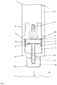
- Figure 1 shows a sampler 1 that was immersed in a liquid and warm molten bath for sampling.
- the sampler 1 has a sample chamber 2.
- the sample chamber 2 shown is a sample 3 which is formed in the exemplary embodiment from a melt, in the exemplary embodiment from a steel melt 4.
- the molten steel 4 with a temperature greater than 600 ° C is in Figure 1 shown as an example as an excerpt.
- the sampler 1 has a filler pipe 5 which has a filler opening 5a and a through hole.
- the filler pipe 5 consists of quartz glass. The filler pipe 5 opens into the sample chamber at the end facing the sampler and is connected to the sample chamber 2.
- the sampler 1 has three heat sinks, namely a lower heat sink 6 and an upper heat sink 8 and an inner heat sink 7.
- the sample chamber 2 is directly surrounded by the lower heat sink 6 and the inner heat sink 7.
- the lower heat sink 6 and the inner heat sink 7 thus surround the sample chamber 2 directly and form the inner wall of the Sample chamber 2.
- the inner wall is thus formed by the two heat sinks 6, 7, since their outer surfaces form a wall of the sample chamber 2. This wall is called the inner wall.
- the sample chamber can thus be seen as a closed space into which the melt can flow.
- the sample chamber 2 can be cooled by means of the heat sinks 6, 7, 8.
- the sampler 1 shows according to Figure 1 at least one connection 9 for the supply of gas or a gas mixture into the sampler 1.
- the connection 9 is also referred to as a hybrid connector.
- an inert gas for example argon, is fed into the sampler 1 through the connection 9.
- the inner heat sink 7 has the shape of a cone, the outer surfaces of the inner heat sink 7 forming trapezoidal surfaces.
- the upper heat sink 8 is adapted to the shape of the inner heat sink, so that this according to FIG Figure 1 forms a corresponding negative form.
- the inner heat sink 7 is held by means of the upper heat sink 8.
- the lower heat sink is adapted to the shape of the upper heat sink 8 and the inner heat sink 7 in such a way that the upper heat sink 8 forms a tight connection with the lower heat sink 6 at the contact surfaces.
- the sample 3 is held in place by means of the lower heat sink 6.
- At least the lower heat sink 6 and the inner heat sink 7 can be detached from one another, so that the sample 3 can be removed from the sampler 1.
- the cooled-down sample 3 remains firmly connected to the lower heat sink 6 when the sample 3 is removed.
- the sampler 1 has at least one gap 11 for the supply of the inert gas used in the exemplary embodiment between an outer wall 7a of the inner cooling body 7 and the outer wall 8a of the upper cooling body 8 opposite the outer wall 7a of the inner cooling body 7.
- a three-dimensional gap 11 is thus present between the two corresponding heat sinks 7, 8.
- the gap 11 runs between the two outer walls 7a, 8a, so that a cone-shaped gap 11 is formed in the sampler 1.
- the sample 3 formed from the molten steel 4 in the sample chamber 2 in the exemplary embodiment can be quickly and easily cooled down to a temperature of about 150 ° C. in time.
- the volume of the respective heat sinks 6, 7, 8 is greater than the volume of the gap 11 (according to FIG Figure 1 ), the volume of the respective heat sink 6, 7, 8 in relation to the volume of the gap 11 preferably forms a ratio of at least 20: 1. This results in a better cooling performance of the sampler 1 according to FIG Figure 1 .
- the sampler 1 also has a measuring system, in the exemplary embodiment a thermocouple 12, by means of which the temperature and thus the position of the sampler 1 in the hot molten steel 4 is determined.
- the sampler 1 for generating a sample 3 has already been held in the molten steel 4 and, after the sample 3 has been generated in the sample chamber 2, has been removed therefrom again.
- the sample 3 is enclosed in the sample chamber 2 by its inner wall.
- the cover 13 is consequently shown in dashed lines in the area of the filling opening 5a of the filling pipe 5, since it has melted in the molten steel 4.
- the protective cap 14 used in the exemplary embodiment is shown in dashed lines for the same reason. Both the cover 13 and the protective cap 14 have melted after the sampler 1 has been immersed in the molten steel 4. Before being immersed in the molten steel 4, the sampler 1 thus has a cover 13 and a protective flap 14.
- the sampler 1 also has a sand body 15 through which the filler pipe 5 runs and in which the thermocouple 12 is located.
- the sand body 15 has a closed shape in the manner of a sand block.
- the filler pipe 5 protrudes from the sand body 15 at some distance according to FIG Figure 1 out.
- the thermocouple 12 is in direct contact with the molten steel 4. The temperature is measured with the aid of the thermocouple 12 in the molten steel 4.
- the upper heat sink 8 has in the exemplary embodiment according to Figure 1 a ventilation opening 16.
- the ventilation opening 16 is closed with an openable membrane 17 in the exemplary embodiment.
- the membrane 17 is opened for gas, the membrane having opened in the exemplary embodiment at least when the molten steel 4 is filled into the sample chamber 2.
- the membrane 17 according to the embodiment in Figure 1 is, for example, a hot-melt adhesive that is influenced by the heat of the melt, so that the membrane 17 opens.
- the ventilation opening 16 has a diameter of 1 mm, the shape of the ventilation opening 16 being a round hole.
- the closed membrane 17 has a pressure resistance of approximately 2 bar and the temperature resistance of the membrane 17 is approximately 70 ° C. in the exemplary embodiment.
- the sampler 1 has a gas outlet opening 18 for the export of the supplied gas.
- the membrane 17 When the membrane 17 is open, the gas supplied to the sampler 1 flows out of the sampler 1 again through the gas outlet opening 18.
- FIG. 1 a support tube 19 made of cardboard is shown.
- the sampler 1 is firmly attached to this support tube 19.
- the other area of the support tube 19 is at one in the Figures 3 to 5 shown by way of example, described in more detail below (not in Figure 1 shown) attached sample holder and thus positioned for taking samples from the molten steel 4.
- This sample holder according to an embodiment according to the Figures 3 to 5 is thus surrounded by the support tube 19 made of cardboard.
- the sampler 1 is thus connected to the respective sample holder on one side thereof.
- the three heat sinks 6, 7, 8 are located according to Figure 1 in the area of the support tube 19.
- the sampler 1 is designed in particular for a sublance (sublance), so that the sampler 1 is used for a sublance and an associated device.
- the sublance in the form of a lance is preferably attached in the area of the connection between the support tube 19 and the sample holder.
- the cardboard carrier tube 19 located at one end of a lance positions the sampler 1 according to FIG Figure 1 according to the preceding statements also with the help of an according to Figures 3 to 5 sample holder not shown.
- the inert gas is fed into the sampler 1 through the connection 9.
- the gas supplied through the connection 9 flows through the three-dimensional gap 11 along the outer walls 7a, 8a between the inner heat sink 7 and the upper heat sink 8, then through the empty sample chamber 2 into the filling pipe 5, which is closed with a cover 13 before it is immersed in the molten steel 4.
- the sampler 1 has a protective cap 14 made of metal.
- the gas thus flows into the filler pipe 5.
- a maximum pressure of 2 bar develops in the sampler 1, so that the membrane 17 remains closed.
- a flow path of the gas through the ventilation opening 16 is consequently not possible because the membrane 17 is still closed.
- the sampler 1 is then immersed in the molten steel 4 in the immersion direction E.
- the sampler 1 is first passed through the slag of the steel melt 4 and then passed into the steel melt 4 itself.
- the position of the sampler in the molten steel 4 is in Figure 1 not shown.
- the protective cap 14 and furthermore the cover 13 melts.
- the protective cap 14 and cover 13 are formed from metal.
- the gas supplied through the connection 9 consequently flows out of the filler pipe 5 into the molten steel 4 in the direction of immersion E from the sampler 1, whereby however no molten steel 4 can penetrate into the filler pipe 5.
- the three heat sinks 6, 7, 8 together with the sample chamber 2 are located above the sand body 15, that is to say they are arranged in the opposite direction to the immersion direction E. Thus, even after they have been immersed in the molten steel 4, they are protected by the carrier tube 19 within the molten bath.
- the gas supply into the sampler 1 is regulated by means of the temperature sensor in the form of the thermocouple 12 by measuring the temperature by means of the thermocouple 12 as described above.
- the gas supply for the subsequent filling of the molten steel 4 into the sample chamber 2 is interrupted in the form of a change in a position of the sampler 1 in the molten steel 4, since the temperature of the molten steel 4 indicates the position of the sampler 1 in this.
- the sand body 15 also heats up in the process.
- the gas supply in the exemplary embodiment is consequently changed briefly so that the sample chamber 2 can subsequently be filled with steel melt 4.
- the gas supply is changed in such a way that the gas supply is switched off.
- the molten steel 4 flows through the hole of the filling pipe into the sample chamber 2, the molten steel entering the hole at the filling opening 5a.
- a negative pressure can be generated, for example, in that a negative pressure is generated at the connection 9. Due to the previously described construction of the sampler 1, the molten steel will then run into the sample chamber 2 and be sucked in by the negative pressure.
- the sampler 1 is pulled out of the molten steel 4 together with the sample holder with the aid of the lance and the support tube 19, so that the sampler 1 according to FIG Figure 1 with the sample chamber 2 filled.
- the membrane 17 in the exemplary embodiment becomes gas-permeable during the filling of the molten steel 4 in the sample chamber 2, since the temperature of the molten steel 4 influences the membrane 17 due to its thermal radiation or the heat sinks 6; 7; 8 heat up in such a way that that the membrane 17 is destroyed.
- the previously closed membrane 17 has thus opened to gas.
- the inert gas flows through the connection 9 and then through the conical gap 11 around the inner heat sink 7, which is attached to the sample on one side of the wall 3 adjoins.
- the gas flows according to this Figure 1 also due to the geometric configuration of the gap 11 around the lower heat sink 6 and the upper heat sink 8, so that this is also (also) cooled.
- the gas then flows out of the ventilation opening 16, so that the gas flowing out of the ventilation opening 16 is discharged from the sampler 1 through the gas outlet opening 18.
- the gas-permeable membrane 17 is also flowed through.
- the newly supplied gas which absorbs the heat of the sampler 1 and flows through the gap 11, causes the temperature of the sample 3 to be cooled down quickly and easily, in the exemplary embodiment to a temperature of approximately 150 ° C. Further lead the dimensions of the respective heat sink 6, 7, 8 and the respective size ratio of heat sinks 6, 7, 8 to the gap 11 to a rapid dissipation of heat.
- the sample 3 At such a temperature of about 150 ° C., it is easily possible for the sample 3 to be removed from the sampler 1 and, for example, fed to an analysis device in the exemplary embodiment.
- the analysis facility is in Figure 1 not shown.
- Figure 2 shows a further, alternative embodiment of a sampler 1a.
- Figure 2 shows a further, alternative embodiment of a sampler 1a.
- Figure 2 shows a sampler 1a with a sample chamber 2 and a sample 3 formed in the sample chamber 2 from a molten metal 4a shown by way of example and in detail.
- the sampler 1a has a connection 9 for the supply of inert gas used in the exemplary embodiment, in particular argon or nitrogen.
- sampler 1 a is firmly positioned on a support tube 19. Furthermore, a (not in Figure 2 shown) sample holder in a design according to Figures 3 to 5 positioned, wherein the carrier tube 19 surrounds this sample holder. Furthermore, the sampler 1a has a filler tube 5 with a hole made of quartz glass or ceramic. The filler pipe 5 has according to Fig. 2 however no cover on.
- the heat sinks 6, 7, 8 are located together with the sample chamber 2 and the sample 3 in a hollow sand body 15, which has a different shape than the embodiment according to FIG Figure 1 .
- the sand body 15 according to Figure 2 namely surrounds the heat sinks 6, 7, 8 in the manner of a housing.
- the filler pipe 5 leads out of the sand body 15 and is partially fixed with cement 20 in the area of the passage.
- the filler tube 5 protrudes somewhat from the hollow sand body 15 according to FIG Figure 2 out.
- the three heat sinks 6, 7, 8 are located in the interior of the sand body 15 according to the preceding statements.
- the lower heat sink 6 is larger in volume than the inner heat sink 7 and the upper heat sink 8.
- the volume of the respective heat sink 6, 7, 8 in relation to the volume of the gap 11 is at least greater than the volume of the gap 11, and a ratio of at least 20: 1 is preferably formed.
- the inner heat sink 7 has a thick, circular disk shape and is spatially enclosed by the upper heat sink 8. Due to the geometric configuration, it is possible that the upper heat sink 8 also engages in the lower heat sink 6, so that a closed connection results between the upper heat sink 8 and the lower heat sink 6, in which the inner heat sink 7 itself is arranged.
- an O-ring 10 is arranged in the area of the contact surface in a groove of the lower heat sink 6. Between the upper heat sink 8 and the inner heat sink 7 is shown in FIG Figure 2 a spatial gap 11 is formed in the form of a spatial shell. A gas- and pressure-tight arrangement is formed due to the O-ring seal and the geometry of the heat sinks 6, 7, 8.
- the inner cooling body 7 has an outer wall 7a which corresponds to the outer wall 8a of the upper cooling body 8, so that the gap 11 is formed which spatially encloses the entire inner cooling body.
- the sampler 1a shown is determined with the aid of a measuring system in the form of an inductive measuring system (not shown) in the molten metal 4a.
- the inductive measuring system it is possible to measure and thus determine the position of the sampler 1a in the molten metal 4a.
- the inductive measuring system is located in the lance (not shown), the position of the sampler 1a in the molten metal 4a being determined by means of the measuring system when, for example, it is completely immersed in the molten metal 4a.
- sampler 1 a It is possible for the sampler 1 a to have a ventilation opening 16 and a gas outlet opening 18. These are in Figure 2 not shown.
- the sampler 1a according to Figure 2 is designed like a hot metal sampler.
- the lance, on which the carrier tube, the sample holder and the sampler 1a are positioned, is inserted in the immersion direction E into the molten metal 4a.
- the sample holder with the surrounding support tube and the sampler 1a are completely in the warm molten bath after immersion.
- an inert gas is fed into the sampler 1a through the connection 9, as described above.
- the gas flows through the gap 11, then through the sample chamber 2, in which there is still no sample 3, and finally through the filler pipe 5 in the direction of the protective cap 14.
- the protective cap 14 melts, so that the supplied gas flows into the molten metal 4a.
- the position of the sampler 1a in the molten metal 4a is determined with the aid of the inductive measuring system, so that the gas supply is stopped in the event of an undesired position.
- the sampler 1a is guided out of the molten metal 4a against the direction of entry E again with the aid of the lance.
- the sample holder is connected to a connection 9 of the respective sampler 1, 1a. According to the preceding explanations, this sample holder is then surrounded by the cardboard tube in the form of the carrier tube 19 and the sample holder is connected to the respective associated lance on the opposite side to the side of the sampler 1, 1a.
- the cardboard tube thus surrounds the sample holder and adjoins the lance and the sampler 1, 1a in each case.
- the change in the supply of gas for filling the melt into the sample chamber 2 can be carried out with the aid of the three sample holders embodied by way of example according to FIGS Figures 3 to 5 realize. These each use different techniques to first pass gas through the connection 9 of the sampler before filling and then to change the gas supply to fill the sample chamber 2. This is described in detail below.
- FIG. 3 shows a sample holder 21a for the preferred accommodation of a sampler 1, which is shown in FIG Figure 1 is shown. It is in the design of the sampler 1 according to Figure 1 Reference is made to the previous statements.
- the sample holder 21a has a contact block 22 as a hybrid component for receiving the sample taker 1.
- the contact block 22 is according to Figure 3 arranged at one end of the sample holder 21a.
- the contact block 22 corresponds to the hybrid connector, which is also referred to as the connection 9 of the sampler 1, so that the contact block 22 and hybrid connector can interlock.
- a receiving device 23 is arranged, which in the exemplary embodiment has a thread.
- several gas lines are arranged in the sample holder 21a.
- the sample holder 21a has in the exemplary embodiment according to Figure 3 a supply line 24a, a discharge line 24b and a gas line 24c.
- the gas line 24c is also located in the contact block 22.
- the supply line 24a Through the supply line 24a, it is possible to feed gas via the contact block 22 into the areas not in Figure 3 to initiate illustrated sampler 1.
- the introduction takes place via the connection 9.
- the gas line 24c runs according to Figure 3 through the contact block 22 and is connected to the sample chamber 2, which is shown in FIG Figure 3 is not shown, thus connected when the sampler 1 and the sample holder 21a are connected to one another.
- the discharge line 24b discharge gas via the contact block 22 from the sampler 1, not shown.
- the discharge line 24b discharge gas via the contact block 22 from the sampler 1, not shown.
- the gas connection 25b is connected to a gas supply line 25a.
- the sample holder 21a according to FIG Figure 3 a switch 26, which is arranged in the sample holder 21a and is connected to the supply line 24a and the discharge line 24b on the one hand and to the gas line 24c on the other hand.
- the change of the state of the switch 26 is carried out with the aid of the switching cable 27a, with a switching cable connection 27b, to which a cable for switching can be plugged, being arranged at the end of the switching cable 27a in the area of the receiving device 23 of the sample holder 21a.
- the sample holder 21a also has measuring contacts 28 which are arranged in the area of the contact block 22.
- the measuring contacts 28 are connected by means of a signal cable 29a, the end of which is located in the region of the receiving device 23, at the end of which a signal cable connection 29b is arranged.
- a signal cable 29a the end of which is located in the region of the receiving device 23, at the end of which a signal cable connection 29b is arranged.
- six measuring contacts 28 are shown one behind the other according to FIG Figure 3 arranged.
- a seal 30 is arranged in the area of the contact block 22, so that a gas-tight connection between the two components is possible when the sample holder 21a and the sampler 1 (not shown) are connected. Between connection 9 according to Figure 1 and the contact block 22 is thus made a gas-tight connection.
- the contact block 22 according to Figure 3 furthermore a gas nozzle 31 through which the gas can flow through the gas line 24c.
- the discharge line 24b is led out of the sample holder 21a through a gas outlet opening 33.
- a gas filter 32a is arranged between this gas outlet opening 33 and the switch 26.
- Another gas filter 32b is arranged in the region of the gas line 24c.
- the sample holder 21a furthermore has a hybrid unit 34 which is arranged between switch 26 and gas nozzle 31, the hybrid unit 34 enabling the gas line 24c and the signal line 29a to be connected directly and firmly to the sampler 1 (not shown) are connectable.
- the contact block 22 is plugged into the connection 9 in a suitable and gas-tight manner as described above.
- the sample holder 21a illustrated is thus that the sample holder 21a has the gas outlet opening 33, the discharge line 24b of the sample holder 21a ending in the gas outlet opening 33.
- the gas filter 32a in the form of an intermediate filter is arranged between the switch 26 and the gas outlet opening 33 of the discharge line 24b.
- the sample holder 21a and the contact block 22 each have a cross section with a circular circumference.
- FIG. 4 shows an alternative embodiment of a sample holder 21b, the same components being given the same reference numbers below and new components being given new reference numbers.
- the sample holder 21b shown has no gas outlet opening 33 and no gas filter 32a in the form of an intermediate filter.
- the sample holder 21b has a supply line 24a and a discharge line 24b, which are connected in the region of the sample holder 21b to form a single gas supply line 25a.
- the supply line 24a and the discharge line 24b are connected to a switch 26 separately.
- An inflow valve 35 is arranged in the supply line 24a and the discharge line 24b is shown in FIG Figure 4 a Venturi nozzle 36 is arranged.
- an opening 37 is arranged inside the Venturi nozzle 36, so that the discharge line 24b has an opening 37 in the region of the Venturi nozzle 36.
- the opening 37 is part of the Venturi nozzle 36 and describes a special embodiment of the Venturi nozzle 36.
- Components shown in the sample holder 21b, such as the receiving device 23, the hybrid unit 34 and the contact block 22, correspond in structure to the components that are already in the sample holder 21a according to FIG Figure 3 previously described. It is based on the designs too Figure 3 referenced and this is corresponding to the statements in accordance with Figure 4 transferred to.
- the in Figure 5 (Fig. 5 ) shown sample holder 21c is described below in such a way that the changes compared to the in Figure 3 sample holder 21a described first below to be discribed.
- the in Figure 5 The sample holder 21c shown has no gas filter 32b and no gas filter 32a in the form of an intermediate filter. Furthermore, the sample holder 21c does not have a gas outlet opening 33. Furthermore, the in Figure 5 The sample holder 21c shown does not have any connections in the form of a switchover cable connection 27b, a gas connection 25b and a signal cable connection 29b.
- the sample holder 21c shown has only a signal cable 29a leading out of the sample holder 21c, a switchover cable 27a and a gas supply line 25a, each of which is led out of the sample holder 21c in the region of the receiving device 23. These extend, for example, directly into the lance that is connected to it. However, it is possible that other cables or lines can be connected in this outside of the sample holder 21c, for example inside the lance, with the aid of a plug connection (not shown) or the like.
- a vacuum chamber 38 is arranged inside the sample holder 21c.
- the vacuum chamber 38 has a volume of approximately 0.3 l in the exemplary embodiment.
- the vacuum chamber 38 is formed in the sample holder 21c in that a part of the discharge line 24b connected to the switch 26, which is arranged in the sample holder 21c, has a larger diameter than the other parts of the discharge line 24b.
- the vacuum chamber 38 is thus formed in the enlarged diameter itself.
- the vacuum chamber 38 is connected to a gas suction line 39 as a further, additionally present line, the gas suction line 39 being connected to a vacuum pump, not shown.
- sample holders 21a, 21b, 21c described can be used, for example, in a device for taking samples in molten metal with a lance, in particular in molten steel with a sublance.
- a device for taking samples in molten metal with a lance in particular in molten steel with a sublance.
- such a device and an associated lance, in particular a sublance are not shown.
- a lance has a lance body which is arranged in such a device.
- a sample holder 21a, 21b, 21c according to one of the explanations Figures 3 to 5 is connectable, with which in particular a sampler 1 according to Figure 1 is connectable for use in molten steel.
- the device has the aid of the respective sample holder 21a, 21b, 21c according to FIGS Figures 3 to 5 a supply line 24a to Introduction of gas via the contact block 22 into the sampler 1 and a discharge line 24b for sucking off gas via the contact block 22 from the sampler 1 and a gas line 24c connected to the sample chamber 2.
- the sample holder 21a, 21b, 21c used in the illustrated device has a length L measured in the axial direction from the contact block 22 to the opposite side of the sample holder 21a, 21b, 21c.
- the switch 26 in the respective sample holder 21a, 21b, 21c is arranged 0.1 ⁇ its length L from the end of the contact block 22 in the exemplary embodiment.
- the sampler 1 and the sample holder 21a, 21b, 21c can be connected with the aid of a carrier tube 19 made of cardboard, whereby the carrier tube 19, which is attached to the sampler 1 itself in the area of the seal 30 on the contact block 22, according to the preceding explanations, is not included in the Figures 3 to 5 is shown.
- FIG Figure 3 The sublance shown is connected to the sample holder 21a, the connection being made in the area of the receiving device 23.
- the associated signal cable connection 29b, the switchover cable connection 27b and the gas connection 25b are each connected to corresponding connections within the sublance.
- the sampler 1 is shown in FIG Figure 1 positioned, the gas nozzle 31 being arranged in the connection 9 of the sampler 1 in such a way that a gas-tight connection between the sample holder 21a and the sampler 1 is created.
- a cardboard carrier tube 19 is positioned between the sampler 1 and the receiving device 23 of the sample holder 21a as part of the sample holder 21a, so that the sample holder 21a is located between the sampler 1 and the end of the carrier tube 19.
- the support tube 19 is firmly connected to the receiving device 23, for example with the aid of an engagement connection in the manner of a thread, the receiving device 23 then for example pressing firmly into the support tube 19 through a wavy surface.
- the sampler 1 is then in this device in an Figure 1 indicated molten steel immersed, before immersion through the supply line 24a, which passes through the Gas supply line 25a is flowed through with an inert gas which has been supplied in advance by the sublance.
- the inert gas fed in through the feed line 24a is then passed through the switch 26, which is in position A, and is thus fed into the gas line 24c, the hybrid unit 34 also being located in the area of the gas line 24c according to the previous explanations.
- the inert gas flows through the gas nozzle 31 into the sampler 1 according to the explanations Figure 1
- the gas initially only enters the filler pipe 5.
- the gas supply through the supply line 24a is closed in accordance with the preceding explanations Figure 1 interrupted by switching the switch 26 to position B.
- the supply of gas through the supply line 24a is interrupted.
- the switch 26 in the sample holder 21a is switched over in such a way that the sample chamber 2 of the sampler is subsequently filled with molten steel 4. Then the sampler 1 as well as the carrier tube 19 and the sample holder 21a are removed from the steel melt with the aid of the movable sublance in the device after the sample chamber 2 has been completely filled with melt.
- the switch 26 is then switched from position B to position C, which in the exemplary embodiment according to FIG Figure 3 corresponds to position A, switched again or switched back. This makes it possible for the sample chamber 2 to be cooled by the supplied gas.
- the cooling is in detail in the embodiment too Figure 1 described.
- the switch 26 is switched over by means of the switchover cable 27a, through which the switch 26 can be switched.
- the switch 26 is switched from position A to position B.
- the sample holder 21a is replaced by the sample holder 21b in a further embodiment.
- the flow of the gas through the sample holder 21b is described below, and differences compared to the previous embodiment with the sample holder 21a are pointed out.
- the inert gas flows through the gas supply line 24d into the supply line 24a and the discharge line 24b.
- the gas flowing through the gas supply line 25a then flows firstly through the supply valve 35 into the switch 26, which is in position A.
- the gas that has flowed in can thus flow through the switch 26 and the gas filter 32b through the hybrid unit 34 into the sampler 1.
- gas, which is supplied from the gas supply line 25a flows to others through the outlet line 24b through the venturi nozzle 36, so that a negative pressure is created between the venturi nozzle 36 and switch 26 due to the special design of the venturi nozzle 36.
- the gas that is supplied through the discharge line 24b is discharged through the opening 37.
- the switch 26 is switched from position A to position B so that the gas flowing through feed line 24a can no longer flow into gas line 24c due to switch position B. Only the gas flowing through the gas supply line 25a can escape through the discharge line 24b and the Venturi nozzle 36 through the opening 37, with a negative pressure continuing between the Venturi nozzle 36 and switch 26 is set up, which is transmitted into the gas line 24c. As a result, a negative pressure arises in the sample chamber 2, which is created in order to suck in melt with the aid of the Venturi nozzle 36 into the sample chamber 2. After the sample chamber 2 has been filled with melt, the switch 26 is switched back to position A, so that the sample chamber 2 can be cooled with the aid of the gas supplied through the supply line 24a.
- the melt 4 is sucked into the sample chamber 2 with the aid of the negative pressure from the vacuum chamber 38 when the switch 26 has been switched from position A to position B.
- the switch 26 is switched back to position A, so that inert gas can flow into the sampler 1 again through the supply line 24a and then through the gas line 24c, so that the sample chamber 2 is cooled.
Description
Die Erfindung betrifft einen Probenhalter nach Anspruch 1, zur Aufnahme eines Probennehmers mit einer Probenkammer für eine sich aus einer Schmelze bildende Probe, vorzugsweise für eine sich bildende Probe aus einer Metallschmelze, insbesondere aus einer Roheisen- oder Stahlschmelze. Des Weiteren betrifft die Erfindung ein Verfahren nach Anspruch 12, zur Probenentnahme aus einer Schmelze mit einer Schmelztemperatur von größer als 600 °C, insbesondere einer Metallschmelze, vorzugsweise einer Roheisen- oder Stahlschmelze. Ferner betrifft die Erfindung eine Vorrichtung nach Anspruch 10, zur Durchführung von Probenentnahmen in Metallschmelzen.The invention relates to a sample holder according to claim 1, for receiving a sampler with a sample chamber for a sample formed from a melt, preferably for a sample formed from a metal melt, in particular from a pig iron or steel melt. The invention further relates to a method according to
Nach dem heute bekannten Stand der Technik ist es möglich, aus einer Schmelze, beispielsweise einer Metallschmelze, Proben zu entnehmen.According to the prior art known today, it is possible to take samples from a melt, for example a metal melt.
Aus der
Aus der
Des Weiteren ist in der
Ferner ist aus der
Sowohl in
Nachteilig bei dem heutzutage bekannten Stand der Technik ist, dass die in der Probenkammer aufgenommene Schmelze, die später die Probe selbst bildet, nur sehr langsam in der Probenkammer abkühlt. Nachfolgende Messungen an der abgekühlten Probe sind daher nur zeitlich vergert möglich. Ferner treten beispielsweise Oxidationsreaktionen aufgrund Umgebungsluft an der noch nicht abgekühlten Probe auf, wenn diese im heißen Zustand aus dem Probennehmer entfernt wird.A disadvantage of the prior art known today is that the melt received in the sample chamber, which later forms the sample itself, cools only very slowly in the sample chamber. Subsequent measurements on the cooled sample are therefore only temporally delayed possible. Furthermore, for example, oxidation reactions occur due to ambient air on the sample that has not yet cooled down if it is removed from the sampler while it is hot.
Eine Aufgabe der Erfindung ist es daher, eine Möglichkeit zu schaffen, mittels der oben beschriebene Nachteile verringert oder vermieden werden können. Insbesondere soll eine Möglichkeit geschaffen werden, eine in einer Probenkammer aufgenommene Schmelze schnell und einfach zu kühlen, so dass die während der Kühlung entstehende feste Probe aus der Schmelze zeitnah nach der Aufnahme der Schmelze entnommen werden kann. Ferner sollen Reaktionen der Probe mit beispielsweise Umgebungsluft durch eine schnelle Kühlung vermieden werden.It is therefore an object of the invention to create a possibility by means of which the disadvantages described above can be reduced or avoided. In particular, a possibility is to be created to cool a melt received in a sample chamber quickly and easily, so that the solid sample produced during the cooling can be removed from the melt promptly after the melt has been taken up. Furthermore, reactions of the sample with, for example, ambient air should be avoided by rapid cooling.
Eine weitere Aufgabe ist es, eine Möglichkeit zu schaffen, die Probenkammer mit Hilfe von technisch einfachen und kostengünstigen Mitteln mit einer Schmelze füllen zu können.Another object is to create a possibility of being able to fill the sample chamber with a melt using technically simple and inexpensive means.
Eine weitere Aufgabe ist es, ein Verfahren zur Probenentnehme aus einer Schmelze zu schaffen, mittels dem die durch die Schmelze gebildete Probe technisch einfach und zeitlich schnell heruntergekühlt werden kann, um diese dann beispielsweise analytisch zu untersuchen.A further object is to create a method for taking samples from a melt, by means of which the sample formed by the melt can be cooled down in a technically simple and timely manner in order to then examine it analytically, for example.
Eine weitere Aufgabe der Erfindung ist es, ein Verfahren zur Probenentnahme aus einer Schmelze zu schaffen, mittels der die Probenkammer schnell füllbar ist.Another object of the invention is to create a method for taking samples from a melt, by means of which the sample chamber can be filled quickly.
Die Aufgabe wird dadurch gelöst, dass der Probennehmer zwischen einem Bereich der Außenseite des inneren Kühlkörpers und dem diesem Bereich der Außenfläche des inneren Kühlkörpers gegenüber liegenden Bereich der Außenfläche des oberen Kühlkörpers zumindest einen Spalt für die Durchleitung von zumindest einem Gas, vorzugsweise von einem Inertgas, insbesondere Argon oder Stickstoff, aufweist und dass das Volumen des jeweiligen Kühlkörpers größer als das Volumen des Spaltes ist, vorzugsweise ein Verhältnis von zumindest 3:1, insbesondere zumindest 5:1, vorzugsweise zumindest 10:1, insbesondere zumindest 20:1, bildet, so dass eine bessere Kühlleistung des Probennehmers entsteht, und dass in dem Probenhalter ein mit der Zuleitung und der Ableitung einerseits und mit der Gasleitung andererseits verbundener Schalter angeordnet ist, mit dem entweder die Zuleitung oder die Ableitung mit der Gasleitung verbindbar sind.The object is achieved in that the sampler has at least one gap between an area of the outside of the inner heat sink and the area of the outer surface of the upper heat sink opposite this area of the outer surface of the inner heat sink for the passage of at least one gas, preferably an inert gas, in particular argon or nitrogen, and that the volume of the respective heat sink is greater than the volume of the gap, preferably a ratio of at least 3: 1, in particular at least 5: 1, preferably at least 10: 1, in particular at least 20: 1, so that a better cooling performance of the sampler arises, and that in the sample holder a switch connected to the supply line and the discharge line on the one hand and to the gas line on the other hand is arranged, with which either the supply line or the discharge line can be connected to the gas line.
Diese Aufgabe wird auch dadurch gelöst, dass mit einem Ende des Lanzenkörpers ein Probenhalter nach einem der Ansprüche 1 bis 9 verbindbar ist, mit dem ein Probennehmer verbindbar ist, wobei die Vorrichtung zumindest eine Zuleitung zur Einleitung von Gas durch das Kontaktstück hindurch in den Probennehmer und zumindest eine Ableitung zum Absaugen von Gas durch das Kontaktstück hindurch aus dem Probennehmer und zumindest eine in dem Probennehmer verlaufende und mit der Probenkammer verbundene Gasleitung aufweist.This object is also achieved in that a sample holder according to one of claims 1 to 9 can be connected to one end of the lance body, with which a sampler can be connected, the device having at least one feed line for introducing gas through the contact piece into the sampler and has at least one discharge line for sucking off gas through the contact piece from the sampler and at least one gas line running in the sampler and connected to the sample chamber.
Die weitere Aufgabe bezüglich des erstgenannten Verfahrens wird dadurch gelöst, dass vor dem Eintauchen zumindest ein Gas, vorzugsweise ein Inertgas, insbesondere Argon oder Stickstoff, in den Probennehmer zugeführt wird, wobei das Gas durch zumindest ein Einfüllstück, vorzugsweise ein Einfüllrohr, aus dem Probennehmer wieder ausströmt, anschließend der Probennehmer in die Schmelze eingetaucht wird, danach die Zufuhr von Gas geändert wird, insbesondere unterbrochen oder in ihrer Richtung umgekehrt wird, nachfolgend sich die Probenkammer mit Schmelze füllt, nachfolgend während oder nach dem Füllen der Probenkammer mit Schmelze erneut Gas in den Probennehmer zugeführt wird, so dass zumindest die Probenkammer durch das zugeführte Gas gekühlt wird.The further object with regard to the first-mentioned method is achieved in that at least one gas, preferably an inert gas, in particular argon or nitrogen, is fed into the sampler before immersion, the gas being returned from the sampler through at least one filler piece, preferably a filler pipe flows out, then the sampler is immersed in the melt, then the supply of gas is changed, in particular interrupted or reversed in its direction, then the sample chamber fills with melt, then during or after the sample chamber is filled with melt again gas in the Sampler is supplied so that at least the sample chamber is cooled by the supplied gas.
Die zuletzt genannte Aufgabe bezüglich des Verfahrens zur Probenentnahme wird dadurch gelöst, dass vor dem Eintauchen zumindest ein Gas, vorzugsweise ein Inertgas, insbesondere Argon oder Stickstoff, in den Probennehmer durch zumindest eine Zuleitung und zumindest eine Gasleitung zugeführt wird, wobei das Gas durch zumindest ein Einfüllstück, vorzugsweise ein Einfüllrohr, aus dem Probennehmer wieder ausströmt, anschließend der Probennehmer in die Schmelze eingetaucht wird, danach die Zufuhr von Gas geändert wird, insbesondere unterbrochen oder in ihrer Richtung umgekehrt wird, indem ein Schalter in den Probenhalter von der Stellung A in die Stellung B umgeschaltet wird, nachfolgend sich die Probenkammer mit Schmelze füllt, nachfolgend während oder nach dem Füllen der Probenkammer mit Schmelze erneut Gas in den Probennehmer zugeführt wird, indem der Schalter von Stellung B in Stellung C umgeschaltet wird und wobei zumindest die Probenkammer durch das zugeführte Gas gekühlt wird.The last-mentioned object with regard to the method for sampling is achieved in that, before immersion, at least one gas, preferably an inert gas, in particular argon or nitrogen, is fed into the sampler through at least one feed line and at least one gas line, the gas through at least one Filler piece, preferably a filler tube, from which the sampler flows out again, then the sampler is immersed in the melt, after which the supply of gas is changed, in particular interrupted or reversed in its direction by a switch in the sample holder from position A to Position B is switched, then the sample chamber fills with melt, then during or after the sample chamber is filled with melt, gas is again fed into the sampler by switching the switch from position B to position C and at least the sample chamber through the supplied Gas is cooled.
Die Erfindung betrifft somit als Hauptanspruch und als Nebenansprüche zumindest einen Probenhalter gemäß Anspruch 1, eine Vorrichtung nach Anspruch 10, und ein Verfahren gemäß Anspruch 12.The invention thus relates as a main claim and as ancillary claims to at least one sample holder according to claim 1, a device according to
Des Weiteren betrifft die Erfindung eine Vorrichtung zur Durchführung von Probenentnahmen in Metallschmelzen mit einer Lanze, insbesondere in Stahlschmelze mit einer Sublanze, wobei die Lanze einen Lanzenkörper aufweist, dadurch gekennzeichnet, dass an einem Ende des Lanzenkörpers ein Probenhalter gemäß der Erfindung anordenbar ist mit einem Kontaktstück zur Aufnahme eines Probennehmers, wobei die Vorrichtung zumindest eine Zuleitung zur Einleitung von Gas durch das Kontaktstück hindurch in den Probennehmer und zumindest eine Ableitung zum Absaugen von Gas durch das Kontaktstück hindurch aus dem Probennehmer und zumindest eine durch das Kontaktstück hindurch verlaufende und durch das Kontaktstück hindurch verlaufende und mit der Probenkammer verbundene Gasleitung aufweist, wobei der Schalter in den Probenhalter angeordnet ist.The invention also relates to a device for taking samples in molten metal with a lance, in particular in molten steel with a sublance, the lance having a lance body, characterized in that a sample holder according to the invention can be arranged with a contact piece at one end of the lance body for receiving a sampler, the device having at least one feed line for introducing gas through the contact piece into the sampler and at least one discharge line for sucking gas through the contact piece from the sampler and at least one running through the contact piece and through the contact piece having extending and connected to the sample chamber gas line, wherein the switch is arranged in the sample holder.
Schließlich betrifft die Erfindung eine Vorrichtung zur Herstellung eines Probenhalters gemäß der Erfindung, dadurch gekennzeichnet, dass die Vorrichtung geeignete Mittel zur Herstellung des Probenhalters aufweist.Finally, the invention relates to a device for manufacturing a sample holder according to the invention, characterized in that the device has suitable means for manufacturing the sample holder.
Ferner betrifft die Erfindung ein Verfahren zur Herstellung eines Probenhalters gemäß der Erfindung mit Hilfe einer Vorrichtung gemäß vorhergehender Ausführung.The invention also relates to a method for producing a sample holder according to the invention with the aid of a device according to the preceding embodiment.
In den Unteransprüchen sind jeweils bevorzugte Ausführungsformen gemäß der Erfindung beansprucht.Preferred embodiments according to the invention are in each case claimed in the subclaims.
Eine Änderung umfasst im Sinne der Erfindung sowohl die Reduzierung, das Ausschalten oder die Umkehr. Bei einer Umkehr, das heißt der Umkehr der Richtung, der Zufuhr wird ein Unterdruck in dem Probennehmer und somit auch in der Probenkammer erzeugt. Diese drei Zustände der Änderung können auch in zeitlich folgender Kombination auftreten.In the context of the invention, a change includes reducing, switching off or reversing. In the event of a reversal, that is, the reversal of the direction, of the supply, a negative pressure is generated in the sampler and thus also in the sample chamber. These three states of change can also occur in the following combination in terms of time.
Mittels des Probennehmers ist es möglich, eine Probe, die aus einer Schmelze gebildet worden ist, mit Hilfe der Kühlkörper technisch einfach und auch schnell auf eine Temperatur herunter zu kühlen, bei der die Probe aus der Probenkammer entnommen werden kann oder alternativ in dem Probennehmer weiter verwendet werden kann. Eine Entnahme in Form eines Entfernens ist durch Fallenlassen oder Manipulierung des Probennehmers möglich, so dass die Probe bei Zerstörung des Probennehmers freigelegt wird. Des Weiteren ist mittels des Probennehmers eine kostengünstige Kühlung der aus der Schmelze sich bildende Probe möglich. Auch mittels des erfindungsgemäßen Verfahrens zur Probenentnahme aus einer Schmelze kann eine Probe mit Hilfe des erneut in den Probennehmer zugeführten Gases einfach, kostengünstig und schnell gekühlt werden. Eine gekühlt Probe reagiert nicht mehr mit beispielsweise Umgebungsluft oder alternativ ist eine auftretende Reaktion oder Veränderung der Probe durch die Kühlung reduziert. Ferner ist es weiter vorteilhaft möglich, dass der Probennehmer nicht für eine Analyse der erstarrten Probe aufgrund seiner Abmessung und der Verwendung eines Inertgases, beispielsweise Argon, in dem Probennehmer präpariert werden muss. Somit sind keine zusätzlichen Fertigungsmaschinen, wie beispielsweise eine Fräsmaschine oder Schleifmaschine im Bereich der Werkshalle, für die Bearbeitung der entnommenen Probe notwendig. Dieses ist als ein besonderer Vorteil anzusehen. Weiterhin ist es gemäß der Erfindung möglich, dass der Zeitaufwand reduziert oder minimiert wird. Es ist weder ein separates Labor, in dem die Probe ausgewertet werden kann, mit irgendwelchen Priorisierungsproblemen noch die Verwendung eines pneumatischen Verschickungssystem oder eines Transportbandes mit auftretenden Restriktionen bei der Verwendung dieser Einreichung notwendig, da die Probe direkt vor Ort, beispielsweise neben den Konverter und der Einheit der verwendeten Lanze im Bereich der Werkshalle mit Hilfe einer Analyseeinheit ausgewertet werden kann. Dieses ist auch als ein weiterer besonderer Vorteil anzusehen. Mittels des erfindungsgemäßen Probenhalters ist es möglich, die Probenkammer des Probennehmers einfach, kostengünstig und schnell mit Schmelze zu befüllen. Ferner ist es vorteilhaft möglich, dass der Aufbau desBy means of the sampler, it is possible, with the aid of the heat sink, to cool a sample that has been formed from a melt, simply and quickly, to a temperature at which the sample is removed from the sample chamber can be or alternatively can be used further in the sampler. A removal in the form of removal is possible by dropping or manipulating the sampler so that the sample is exposed if the sampler is destroyed. Furthermore, a cost-effective cooling of the sample formed from the melt is possible by means of the sampler. Also by means of the method according to the invention for taking samples from a melt, a sample can be cooled simply, inexpensively and quickly with the aid of the gas fed back into the sampler. A cooled sample no longer reacts with, for example, ambient air or, alternatively, a reaction or change in the sample that occurs is reduced by the cooling. Furthermore, it is also advantageously possible that the sampler does not have to be prepared in the sampler for an analysis of the solidified sample due to its dimensions and the use of an inert gas, for example argon. This means that no additional production machines, such as a milling machine or grinding machine in the workshop area, are necessary for processing the sample taken. This is to be seen as a particular advantage. Furthermore, according to the invention, it is possible for the expenditure of time to be reduced or minimized. Neither a separate laboratory in which the sample can be evaluated, with any prioritization problems, nor the use of a pneumatic dispatch system or a conveyor belt with restrictions that arise when using this submission is necessary, as the sample is available directly on site, for example next to the converter and the Unit of the lance used in the workshop area can be evaluated with the help of an analysis unit. This is also to be regarded as a further special advantage. By means of the sample holder according to the invention it is possible to fill the sample chamber of the sampler simply, inexpensively and quickly with melt. Furthermore, it is advantageously possible that the structure of the
Probennehmers konstruktiv einfach und kostengünstig ist. Des Weiteren lässt sich der Probennehmer einfach in bestehende Vorrichtungen zur Probenentnahme integrieren.Sampler is structurally simple and inexpensive. The sampler can also be easily integrated into existing sampling devices.
Das mit der Probenkammer verbundene Einfüllstück, durch das die Schmelze aus dem Schmelzbad in die Probenkammer fließt, ist beispielsweise aus einem Quarzglas, einer Keramik oder dergleichen gebildet.The filler piece connected to the sample chamber, through which the melt flows from the molten bath into the sample chamber, is formed, for example, from a quartz glass, a ceramic or the like.
Der untere, obere und/oder innere Kühlkörper ist vorteilhaft aus einem Metall oder einer Metalllegierung, beispielsweise einer Stahllegierung, ausgestaltet, die bevorzugt einen höheren Schmelzpunkt aufweist als die Schmelze, die die spätere Probe in der Probenkammer bildet.The lower, upper and / or inner heat sink is advantageously made of a metal or a metal alloy, for example a steel alloy, which preferably has a higher melting point than the melt that will later form the sample in the sample chamber.
Es ist ferner alternativ oder ergänzt möglich, dass der Kühlkörper beschichtet ist. Dadurch ist es möglich, beispielsweise eine Oxidation und/oder eine Gefügeveränderung der Probe während des Abkühlens der Probe zu vermeiden, wobei die jeweilige Außenseite der Probe an den zugeordneten, beschichteten Kühlkörper bevorzugt angrenzt.As an alternative or in addition, it is also possible for the heat sink to be coated. This makes it possible to avoid, for example, an oxidation and / or a structural change in the sample while the sample is being cooled, the respective outer side of the sample preferably adjoining the assigned, coated heat sink.
Eine weitere vorteilhaft Ausgestaltung des Probennehmers ist, dass zumindest der untere Kühlkörper und der innere Kühlkörper eine Wand der Probenkammer bilden, wobei die Wand durch einen Bereich der jeweiligen Außenfläche des unteren Kühlkörpers und des inneren Kühlkörpers gebildet ist, so dass sich zwischen unterem Kühlkörper und innerem Kühlkörper eine Probenkammer mit Hohlraum ausbildet.Another advantageous embodiment of the sampler is that at least the lower heat sink and the inner heat sink form a wall of the sample chamber, the wall being formed by a region of the respective outer surface of the lower heat sink and the inner heat sink, so that between the lower heat sink and the inner heat sink Heat sink forms a sample chamber with a cavity.
Indem sich die abkühlende Probe zwischen unterem Kühlkörper und innerem Kühlkörper befindet, ist es möglich, die Probe besonders einfach und schnell zu kühlen. Es grenzen nämlich die zugeordnete Fläche des unteren Kühlkörpers und des inneren Kühlkörpers bevorzugt direkt an die Probe an, so dass Wärme direkt über den jeweiligen Kühlkörper abgeleitet werden kann, die dann vom strömenden Gas aus dem Probennehmer abgeführt wird.Because the cooling sample is located between the lower heat sink and the inner heat sink, it is possible to cool the sample particularly easily and quickly. Namely, the assigned surface of the lower heat sink and the inner heat sink preferably directly adjoin the sample, so that heat can be dissipated directly via the respective heat sink, which heat is then dissipated from the sampler by the flowing gas.
Eine weitere vorteilhafte Ausgestaltung des Probennehmers ist, dass der Probennehmer zumindest einen Anschluss für die Zufuhr von Gas, vorzugsweise von einem Inertgas, insbesondere Argon oder Stickstoff, aufweist. Der Anschluss wird auch als Hybridconnector bezeichnet. Mittels des Anschlusses ist es möglich, die von der Probe auf den zugeordneten Kühlkörper, insbesondere den unteren und inneren Kühlkörper übertragene Wärme mit Hilfe eines durch den Anschluss zugeführten Gases abzuführen. Dabei ist es möglich, die Menge an zugeführtem Gas auf den jeweils erwünschten Kühlungseffekt anzupassen. Es wird bevorzugt ein Inertgas, insbesondere Argon oder Stickstoff, verwendet, so dass es zu keiner Reaktion der Probe mit dem zugeführten Gas kommt. Eine weitere bevorzugte Aufgabe des zugeführten Gases durch den Anschluss ist auch, die Probenkammer bis zur Aufnahme der Schmelze in diese frei von der Schmelze zu halten, indem aus dem Einfüllstück des Probennehmers Gas in die Schmelze hinausströmt, so dass keine Schmelze in den Probennehmer zunächst eindringen kann.Another advantageous embodiment of the sampler is that the sampler has at least one connection for the supply of gas, preferably an inert gas, in particular argon or nitrogen. The connection is also known as a hybrid connector. By means of the connection it is possible to dissipate the heat transferred from the sample to the associated heat sink, in particular the lower and inner heat sink, with the aid of a gas supplied through the connection. It is possible to adapt the amount of gas supplied to the cooling effect desired in each case. An inert gas, in particular argon or nitrogen, is preferably used so that the sample does not react with the gas supplied. Another preferred task of the gas supplied through the connection is to keep the sample chamber free of the melt until the melt is absorbed into it, in that gas flows out of the filler piece of the sampler into the melt, so that no melt initially penetrates the sampler can.
Eine weitere vorteilhafte Ausgestaltung des Probennehmers ist, dass zumindest der untere und der innere Kühlkörper voneinander lösbar sind. Durch diese Anordnung ist die Probe einfach aus der Probenkammer, die bevorzugt zwischen unterem Kühlkörper und innerem Kühlkörper gebildet wird, zu entnehmen. Dabei sind die heruntergekühlte Probe und der untere Kühlkörper gemäß einer Ausgestaltung der Erfindung nicht voneinander lösbar, wenn die heruntergekühlte Probe entnommen wird.Another advantageous embodiment of the sampler is that at least the lower and the inner cooling body can be detached from one another. With this arrangement, the sample can be easily removed from the sample chamber, which is preferably formed between the lower heat sink and the inner heat sink. This includes the cooled sample and the lower heat sink according to one embodiment of the invention, not detachable from one another when the cooled-down sample is removed.
Mittels des Spaltes ist es möglich, zum einen eine bestimmte Menge an Gas in den Probennehmer strömen zu lassen. Zum anderen ist es dadurch möglich, eine größere Wärmemenge, die sich beispielsweise nach Aufnahme der Schmelze in die Probenkammer in dem Probennehmer bildet, abzuführen. Die Form des Spaltes kann dabei beliebig räumlich ausgebildet sein, beispielsweise kugelförmig, ellipsenförmig, kegelförmig, trapezförmig und/oder eine Kombination aus diesen. Alternativ oder ergänzend ist auch eine Freiformfläche möglich, die unterschiedliche Ausgestaltungen im Spalt aufweist.By means of the gap it is possible, on the one hand, to allow a certain amount of gas to flow into the sampler. On the other hand, it is thereby possible to dissipate a larger amount of heat that is formed in the sampler, for example after the melt has been taken up in the sample chamber. The shape of the gap can be designed spatially as desired, for example spherical, elliptical, conical, trapezoidal and / or a combination of these. As an alternative or in addition, a free-form surface is also possible, which has different configurations in the gap.
Eine weitere vorteilhafte Ausgestaltung des Probennehmers ist, dass der Probennehmer zumindest eine Gasaustrittsöffnung für die Ausfuhr des zugeführten Gases aufweist. Gemäß vorhergehender Ausführung ist es vor Aufnahme der Schmelze in der Probenkammer möglich, dass zugeführtes Gas aus dem Einfüllstück heraus in die Schmelze strömt. Nachdem durch das Einfüllstück Schmelze in die Probenkammer eingeströmt ist, ist dieser Weg zumindest beeinträchtigt oder versperrt, so dass zugeführtes Gas in gleicher Menge wie vor dem Einfüllen der Schmelze zur Kühlung des Probennehmers anderweitig abgeführt werden muss, um einen Druckanstieg zu vermeiden. Dazu dient eine Gasaustrittsöffnung, die insbesondere nach der Schmelzaufnahme eine Zufuhr von Gas zur Kühlung durch beispielsweise den Spalt zwischen den Kühlkörpern weiterhin ermöglicht und dieses zugeführte Gas dann wieder aus dem Probennehmer herausführt, ohne durch die Probenkammer strömen zu müssen.Another advantageous embodiment of the sampler is that the sampler has at least one gas outlet opening for the export of the supplied gas. According to the previous embodiment, before the melt is received in the sample chamber, it is possible for the gas supplied to flow out of the filler piece into the melt. After melt has flown into the sample chamber through the filler piece, this path is at least impaired or blocked, so that the gas supplied in the same amount as before the melt was poured into the sample chamber has to be discharged in some other way in order to avoid an increase in pressure. A gas outlet opening is used for this purpose, which continues to allow gas to be supplied for cooling through the gap between the heat sinks, for example after the melt has been absorbed, and which then leads this supplied gas back out of the sampler without having to flow through the sample chamber.
In einer weiteren vorteilhaften Ausgestaltung des Probennehmers weist zumindest einer der Kühlkörper, vorzugsweise der obere Kühlkörper zumindest eine Lüftungsöffnung auf. Die Lüftungsöffnung im Bereich des Kühlkörpers hat den Vorteil, dass die dem Probennehmer zugeführte zur Kühlung verwendete Gasmenge nach der Probennahme durch die Lüftungsöffnung hindurch zur Gasaustrittsöffnung geführt werden kann.In a further advantageous embodiment of the sampler, at least one of the cooling bodies, preferably the upper cooling body, has at least one ventilation opening. The ventilation opening in the area of the heat sink has the advantage that the amount of gas used for cooling that is supplied to the sampler can be passed through the ventilation opening to the gas outlet opening after the sampling.
Eine weitere vorteilhafte Ausgestaltung ist, dass die Lüftungsöffnung mit zumindest einem öffnenbaren Verschluss, vorzugsweise einer öffnenbaren Membran, verschließbar ist, wobei sich der Verschluss während oder nach dem Auffüllen der Schmelze in die Probenkammer öffnet. Gemäß vorhergehender Ausführung ist es vorgesehen, dass zunächst Gas durch die Kühlkörper hindurch, anschließend durch die Probenkammer und anschließend aus dem Einfüllstück herauszuführen, bis es zu einer Aufnahme der Schmelze in die Probenkammer kommt. Nach dem Auffüllen der Schmelze in der Probenkammer ist zumindest teilweise, insbesondere vollständig, der Weg der Strömung des Gases durch das Einfüllstück versperrt, so dass zur Kühlung notwendiges Gas wie vorher nun durch einen öffnenbaren Verschluss hindurch aus dem Probennehmer herausgeführt werden kann. Der Verschluss öffnet sich dabei während oder nach dem Auffüllen der Schmelze in die Probenkammer. Die Öffnung kann dabei mittels Druckanstieg erzeugt werden, indem der Verschluss erst bei einem bestimmten Druck öffnet. Alternativ oder ergänzend ist es möglich, dass der Verschluss durch die Wärmemenge der den Probennehmer umgebenden Schmelze, die nach dem Eintauchen des Probennehmers in die warme, flüssige Schmelze auftritt, für einen Wechsel des Zustandes von geschlossenem Verschluss zu offenem Verschluss beeinflusst wird.A further advantageous embodiment is that the ventilation opening can be closed with at least one openable closure, preferably an openable membrane, the closure opening during or after the filling of the melt into the sample chamber. According to the previous embodiment, it is provided that gas is first fed through the heat sink, then through the sample chamber and then out of the filler piece until the melt is absorbed into the sample chamber. After the melt has been filled in the sample chamber, the path of the flow of the gas through the filler piece is at least partially, in particular completely, blocked, so that the gas required for cooling can now, as before, be led out of the sampler through an openable closure. The closure opens during or after the melt is filled into the sample chamber. The opening can be created by means of an increase in pressure, in that the closure only opens at a certain pressure. Alternatively or in addition, it is possible that the closure is influenced by the amount of heat of the melt surrounding the sampler, which occurs after the sampler is immersed in the warm, liquid melt, for a change in the state from closed closure to open closure.
Die Lüftungsöffnung kann beispielsweise eine runde oder eckige Form oder eine Kombination aus beiden haben, beispielsweise eine runde Form mit geraden Anteilen, eine ellipsenförmige Form mit eckigen Anteilen oder dergleichen.The ventilation opening can, for example, have a round or angular shape or a combination of both, for example a round shape with straight parts, an elliptical shape with angular parts or the like.
In einer weiteren vorteilhaften Ausgestaltung des Probennehmers weist die Lüftungsöffnung einen Durchmesser von etwa 0,7 mm bis etwa 1,3 mm, vorzugsweise 1,0 mm, auf.In a further advantageous embodiment of the sampler, the ventilation opening has a diameter of approximately 0.7 mm to approximately 1.3 mm, preferably 1.0 mm.
Eine weitere vorteilhafte Ausgestaltung des Probennehmers ist, dass der Verschluss, vorzugsweise die Membran, zumindest eine Kunststoffverbindung, vorzugsweise ein Klebeband, einen Schmelzkleber, einen PVC-Kunststoffstopfen, ein Schließventil mit einer Schmelzverbindung aus Kunststoff oder dergleichen, aufweist. Mittels der Wärme der Schmelze in der Probenkammer ist es möglich, dass der aus einem Kunststoff bestehende Verschluss schmilzt und somit deformiert oder aufgelöst wird, so dass der Verschluss sich teilweise oder vollständig öffnet. Dadurch kann zugeführtes Gas weiterhin in einer vorgesehenen und/oder notwendigen Menge zur Kühlung durch den Probennehmer gemäß vorhergehenden Ausführungen weiter hindurch strömen. Es ist alternativ oder ergänzend möglich, dass durch Einfluss von Druck, der durch die Menge an zugeführtem Gas erzeugt wird, den Verschluss bestehend aus einer Kunststoffverbindung zu öffnen, beispielsweise durch Deformation des Verschlusses.A further advantageous embodiment of the sampler is that the closure, preferably the membrane, has at least one plastic connection, preferably an adhesive tape, a hot melt adhesive, a PVC plastic stopper, a closing valve with a plastic melt connection or the like. By means of the heat of the melt in the sample chamber, it is possible that the closure, which is made of a plastic, melts and is thus deformed or dissolved, so that the closure opens partially or completely. As a result, supplied gas can continue to flow through the sampler according to the preceding explanations in an intended and / or necessary amount for cooling. As an alternative or in addition, it is possible for the closure consisting of a plastic compound to be opened by the influence of pressure generated by the amount of gas supplied, for example by deformation of the closure.
Das zugeführte Gas wird beispielsweise dann nach Veränderung der Eigenschaften des Verschlusses aus der Lüftungsöffnung oder anschließend aus der Gasaustrittsöffnung herausströmen.The supplied gas will then flow out of the ventilation opening or subsequently out of the gas outlet opening, for example after changing the properties of the closure.
In einer weiteren vorteilhaften Ausgestaltung des Probennehmers weist der Verschluss, vorzugsweise die Membran, eine Druckbeständigkeit von etwa 0,5 bar bis etwa 4 bar, insbesondere zwischen 1,7 bar und etwa 2,3 bar, vorzugsweise etwa 2,0 bar, auf. Es ist somit möglich, dass bei einem bestimmten Druck sich der Verschluss erst öffnet. Ein hoher Druck im Bereich des Verschlusses lässt sich durch eine große Zufuhr von Gas erzeugen, beispielsweise in dem Moment, in dem besonders stark gekühlt werden soll.In a further advantageous embodiment of the sampler, the closure, preferably the membrane, has a pressure resistance of approximately 0.5 bar to approximately 4 bar, in particular between 1.7 bar and approximately 2.3 bar, preferably approximately 2.0 bar. It is therefore possible that the closure only opens at a certain pressure. A high pressure in the The area of the closure can be generated by a large supply of gas, for example at the moment when particularly strong cooling is to be carried out.
Eine weitere vorteilhafte Ausgestaltung des Probennehmers ist, dass der Verschluss, vorzugsweise die Membran, eine Temperaturbeständigkeit von etwa 50 °C bis etwa 90 °C, vorzugsweise etwa 70 °C, aufweist. Dadurch ist es möglich, dass der Verschluss beim Eintauchen des Probennehmers sich nicht schon beim Durchtritt durch die in der Regel auf die Schmelze sich befindenden Schlacke öffnet. Eine Temperaturbeständigkeit führt auch dazu, dass der Verschluss nicht an der Umgebungsluft usw. (und so weiter) öffnet. Beim Einführen des Probennehmers in die Schmelze kommt es zu einem zeitlich verzögerten Anstieg der Temperatur im Bereich des Verschlusses, so dass eine Temperatur von etwa 70 °C an diesem leicht verzögert eintritt, beispielsweise, wenn der Probennehmer schon wieder aus der Schmelze entnommen ist.Another advantageous embodiment of the sampler is that the closure, preferably the membrane, has a temperature resistance of about 50 ° C to about 90 ° C, preferably about 70 ° C. This makes it possible for the closure not to open when the sampler is immersed when it passes through the slag, which is usually on the melt. A temperature resistance also means that the closure does not open in the ambient air etc. (and so on). When the sampler is introduced into the melt, there is a delayed rise in the temperature in the area of the closure, so that a temperature of around 70 ° C occurs with a slight delay, for example when the sampler has already been removed from the melt.
In einer besonderen bevorzugten Ausgestaltung ist der Verschluss als Membran ausgestaltet, die eine bestimmte Gasmenge nur hindurch lässt. Die Menge kann dabei beispielsweise abhängig vom Druck und/oder der Umgebungstemperatur um die Membran sein, insbesondere mit Fokus auf die dem Probennehmer zugeführte Wärmemenge und Gasmenge.In a particularly preferred embodiment, the closure is designed as a membrane that only allows a certain amount of gas to pass through. The amount can be dependent on the pressure and / or the ambient temperature around the membrane, in particular with a focus on the amount of heat and amount of gas supplied to the sampler.
Eine weitere vorteilhafte Ausgestaltung ist, dass der Probennehmer zumindest ein Messsystem, vorzugsweise einen Temperatursensor, insbesondere ein Thermoelement, zur Ermittlung der Lage des Probennehmers in der Schmelze aufweist. Dadurch lässt sich die Gaszufuhr in den Probennehmer individuell regeln. Alternativ oder ergänzend ist es dadurch möglich, den Zeitpunkt für den Eintritt der Schmelze durch beispielsweise das Einfüllrohr in die Probenkammer optimal zu bestimmen. Eine Schlackekappe schmilzt bei einer bestimmten Temperatur (z.B. bei 1000°C) und ein Gasstrom in dem Probennehmer kann so geschaltet werden, dass Schmelze in die Probenkammer fließt und eine Probe genommen wird. Alternativ ist es möglich, dass eine Lanze gemäß der Erfindung ein Messsystem, vorzugsweise ein induktives Messsystem, aufweist, wobei der Probennehmer an der Lanze positioniert ist, insbesondere befestigt ist. Zwischen Lanze und Probennehmer ist es möglich, dass ein Probenhalter als Verbindungselement angeordnet ist. Mittels des induktiven Messsystems ist es möglich, die Position des Probennehmers in der Schmelze zu ermitteln. So ist es möglich, den Übergang von Schlacke zu Schmelze zu detektieren und zumindest zu messen, so dass bei oder nach Ermittlung des Übergangs die Gaszufuhr geändert werden kann. So ist es beispielsweise möglich, die Gaszufuhr in den Probennehmer dann zu ändern, wenn der Probennehmer von der Schlacke in die Schmelze eingetaucht worden ist. Das induktive Messsystem weist bevorzugt eine Drahtspule, beispielsweise zur Messung der auftretenden Induktion von Übergang von Schlacke zu Schmelze, auf.Another advantageous embodiment is that the sampler has at least one measuring system, preferably a temperature sensor, in particular a thermocouple, for determining the position of the sampler in the melt. This allows the gas supply to the sampler to be regulated individually. As an alternative or in addition, it is thereby possible to optimally determine the point in time for the entry of the melt through, for example, the filler pipe into the sample chamber. A slag cap melts at a certain temperature (eg at 1000 ° C) and a gas flow in the sampler can be switched so that melt flows into the sample chamber and a sample is taken. Alternatively, it is possible for a lance according to the invention to have a measuring system, preferably an inductive measuring system, the sampler being positioned, in particular fastened, on the lance. It is possible that a sample holder is arranged as a connecting element between the lance and the sampler. Using the inductive measuring system, it is possible to determine the position of the sampler in the melt. It is thus possible to detect and at least measure the transition from slag to melt, so that the gas supply can be changed during or after the transition is determined. For example, it is possible to change the gas supply to the sampler when the sampler has been immersed in the melt by the slag. The inductive The measuring system preferably has a wire coil, for example for measuring the induction that occurs from the transition from slag to melt.
In einer weiteren vorteilhaften Ausgestaltung ist mittels des Spaltes und mittels der Zuführung von Gas die sich aus der Schmelze gebildete Probe in der Probenkammer auf eine Temperatur von etwa 90°C bis etwa 200°C, vorzugsweise etwa 150°C, herunterkühlbar. Gemäß vorhergehenden Ausführungen wird bevorzugt das Gas durch einen Spalt zwischen den jeweiligen Kühlkörpern hindurchgeführt, wodurch eine schnelle und einfache Kühlung von der Schmelztemperatur auf gewünschte Temperaturen, beispielsweise 150°C oder weniger, möglich ist.In a further advantageous embodiment, the sample formed from the melt in the sample chamber can be cooled down to a temperature of approximately 90 ° C. to approximately 200 ° C., preferably approximately 150 ° C., by means of the gap and the supply of gas. According to the preceding statements, the gas is preferably passed through a gap between the respective heat sinks, as a result of which rapid and simple cooling from the melting temperature to the desired temperatures, for example 150 ° C. or less, is possible.
Eine weitere vorteilhafte Ausgestaltung ist, dass das Einfüllstück zumindest mittels einer Schutzkappe, vorzugsweise mittels einer Schutzkappe aus Metall, abdeckbar ist. Dieses ermöglicht ein einfaches und schonendes Einführen des Probennehmers in die Schmelze, da diese durch die Schutzkappe abgedeckt ist, die nach Eintritt beispielsweise durch die Schlacke und dann in die Schmelze erst schmilzt. Somit liegt das Einfüllstück für die Aufnahme der Schmelze in die Probenkammer in der Schmelze erst nach dem Schmelzen frei. Es wird dabei jedoch noch Gas vor dem Eintritt der Schmelze in die Probenkammer aus dem Einfüllstück innerhalb der Schmelze herausgeführt.Another advantageous embodiment is that the filler piece can be covered at least by means of a protective cap, preferably by means of a protective cap made of metal. This enables the sampler to be inserted easily and gently into the melt, since it is covered by the protective cap, which first melts after entering, for example, through the slag and then into the melt. The filler piece for receiving the melt in the sample chamber is therefore only exposed in the melt after melting. However, gas is still led out of the filler piece within the melt before the melt enters the sample chamber.
In einer weiteren vorteilhaften Ausgestaltung ist der Probennehmer an einer Lanze und/oder an einem Trägerstück, vorzugsweise an einem Trägerrohr, insbesondere an einem Probenhalter und einem Trägerrohr, insbesondere einem Trägerrohr aus Pappe, positionierbar. Dadurch ist es möglich, dass der Probennehmer sowohl manuell als auch automatisch in die Schmelze eingeführt werden kann. Insbesondere ist es dadurch möglich, den Probennehmer an einer beliebigen Stelle in der Schmelze zu positionieren. Ferner ist es dadurch möglich, die Lanze wieder zu verwenden, indem ein Trägerrohr verwendet wird, das nach der Aufnahme der Schmelze und nach Abkühlen der Schmelze in der Probenkammer zu einer Probe insoweit beschädigt ist, dass dieses nicht mehr verwendet werden kann. Dabei wird der Probenhalter durch das Trägerrohr selbst geschützt. Es handelt sich somit um einen Wegwerfartikel bei dem Trägerrohr, der einmalig verwendet wird, um insbesondere auch die mehrfach verwendbare Lanze zu schützen. Es ist beispielsweise möglich, auf eine Lanze oder auf einen Probenhalter ein Trägerrohr, das eine bestimmte Länge aufweist, zu positionieren und somit einen bestimmten Abstand zwischen Lanze und Probennehmer zu erzeugen, wenn das Trägerrohr an seinem der Lanze entgegensetzten Ende den Probennehmer aufnimmt. Innerhalb des Trägerrohres befindet sich bevorzugt der Probenhalter, der beispielweise den Probennehmer und die Lanze verbindet. Es werden das Trägerrohr und der Probennehmer so in die Schmelze eingeführt, dass diese in direktem Kontakt mit der Schmelze stehen. Der Probenhalter selbst wird dabei durch das Trägerrohr geschützt. Die Lanze ist gegen die Schmelze auch geschützt.In a further advantageous embodiment, the sampler can be positioned on a lance and / or on a carrier piece, preferably on a carrier tube, in particular on a sample holder and a carrier tube, in particular a carrier tube made of cardboard. This makes it possible for the sampler to be introduced into the melt both manually and automatically. In particular, this makes it possible to position the sampler at any point in the melt. It is also possible to reuse the lance by using a carrier tube which, after receiving the melt and after cooling the melt in the sample chamber to form a sample, is damaged to the extent that it can no longer be used. The specimen holder is protected by the carrier tube itself. The carrier tube is therefore a disposable item that is used once, in particular to protect the lance that can be used repeatedly. For example, it is possible to position a carrier tube with a certain length on a lance or on a sample holder and thus generate a certain distance between the lance and the sampler when the carrier tube receives the sampler at its end opposite the lance. The sample holder, for example the sampler, is preferably located inside the support tube and the lance connects. The carrier tube and the sampler are inserted into the melt in such a way that they are in direct contact with the melt. The specimen holder itself is protected by the carrier tube. The lance is also protected against the melt.
Es ist dabei möglich, den jeweiligen Kühlkörper unterschiedlich geometrisch auszugestalten. Es ist beispielsweise möglich, den inneren Kühlkörper in rechteckform, quadratform, scheibenform, dreieckform, pyramidenform, kegelform, kugelform, Kreisform oder dergleichen, beispielsweise einer Kombination aus vorhergehend genannten, auszugestalten. Insbesondere bei den geometrisch zweidimensionalen Formen wie Dreieck, Rechteck, Kreis, Quadrat oder dergleichen weist der innere Kühlkörper auch eine bestimmte Dicke auf, so dass sich eine dreidimensionale räumliche Ausgestaltung des Kühlkörpers ergibt.It is possible to design the respective heat sink in different geometries. It is possible, for example, to design the inner heat sink in a rectangular, square, disc, triangular, pyramidal, conical, spherical, circular or similar shape, for example a combination of the aforementioned. In particular in the case of geometrically two-dimensional shapes such as triangles, rectangles, circles, squares or the like, the inner heat sink also has a certain thickness, so that a three-dimensional spatial configuration of the heat sink results.
Sie sind dabei besonders bevorzugt die Formen des unteren Kühlkörpers und des oberen Kühlkörpers an die Form des inneren Kühlkörpers angepasst, so dass eine optimale Kühlung durch sich bildende Spalte im Bereich der Probenkammer und des Probennehmers ergibt. Alternativ oder ergänzend ist es auch möglich, dass die untere oder obere Form des Kühlkörpers die Formgebung des inneren Kühlkörpers beeinflusst.They are particularly preferably adapted to the shape of the lower heat sink and the upper heat sink to the shape of the inner heat sink, so that optimal cooling results from the gaps that form in the area of the sample chamber and the sampler. Alternatively or in addition, it is also possible that the lower or upper shape of the cooling body influences the shape of the inner cooling body.
Durch die Form des Kühlkörpers ist es möglich, die Form des Spaltes zu beeinflussen (oder umgekehrt).Due to the shape of the heat sink, it is possible to influence the shape of the gap (or vice versa).
Es ist weiterhin vorgesehen, den Durchmesser oder die Abmessungen des erfindungsgemäßen Spaltes, der besonders bevorzugt zwischen oberem Kühlkörper und innerem Kühlkörper verläuft, auf die jeweiligen notwendigen Mengen an Gas anzupassen. Unter einem Spalt versteht man dabei auch eine flächige Ausgestaltung, beispielsweise ein kegelförmiger Spalt, der einen korrespondierenden kegelförmigen inneren Kühlkörper flächig umschließt. Dadurch ist eine optimale Kühlung der Kühlkörper und somit der Probenkammer und letztendlich des Probennehmers möglich.It is also provided that the diameter or the dimensions of the gap according to the invention, which particularly preferably runs between the upper heat sink and the inner heat sink, are adapted to the respective amounts of gas required. In this context, a gap is also understood to be a flat configuration, for example a conical gap, which surrounds a corresponding conical inner heat sink over a large area. This enables optimal cooling of the heat sink and thus of the sample chamber and ultimately of the sampler.
Bei dem erfindungsgemäßen Verfahren wird bevorzugt das Gas durch den Anschluss für die Zufuhr von Gas dem Probennehmer zugeführt. Der Anschluss befindet sich bevorzugt innerhalb des Probenhalters. Dadurch ist es einfach und kostengünstig möglich, in den Probennehmer Gas zuzuführen. Insbesondere ist es dadurch möglich, verschiedene Gase, die jeweils auf die Schmelze angepasst sind, an einen solchen Anschluss anzuschließen. Beispielsweise ist es möglich, bei der Schmelze A an den Anschluss des Gas A und bei der Schmelze B an den jeweiligen Anschluss das Gas B oder das Gasgemisch B' anzuschließen.In the method according to the invention, the gas is preferably supplied to the sampler through the connection for the supply of gas. The connection is preferably located inside the specimen holder. This makes it possible to feed gas into the sampler in a simple and inexpensive manner. In particular, this makes it possible to connect different gases, each of which is adapted to the melt, to such a connection. For example, in the case of melt A, it is possible to connect gas B or the gas mixture B 'to the connection for gas A and in melt B to the respective connection.
Bevorzugt strömt das Gas durch zumindest einen Spalt zwischen zumindest inneren Kühlkörper und oberem Kühlkörper. Gemäß vorhergehenden Ausführungen ist dadurch eine optimale und schnelle Kühlung der zu anfangs flüssigen Schmelze in der Probenkammer zur Erzeugung einer verwendbaren Probe möglich. Somit ist eine Entnahme der schnell gekühlten Probe aus der Probenkammer möglich, ohne dass es zu äußeren Einflüssen, wie Oxidationsreaktionen, auf der Probe nach Entfernen dieser aus dem Probennehmer kommt.The gas preferably flows through at least one gap between at least the inner heat sink and the upper heat sink. According to the preceding statements, this enables optimal and rapid cooling of the initially liquid melt in the sample chamber in order to generate a usable sample. It is thus possible to remove the rapidly cooled sample from the sample chamber without external influences, such as oxidation reactions, occurring on the sample after it has been removed from the sampler.
Das Gas strömt bevorzugt vor dem Einfüllen der Schmelze nur aus dem Einfüllstück aus und während oder nach dem Auffüllen der Schmelze in die Probenkammer durch zumindest eine Lüftungsöffnung aus. Gemäß vorhergehenden Ausführungen ist es dabei möglich, zu verhindern, dass vor dem eigentlich gewollten Einströmen der Schmelze in die Probenkammer Teile von Schmelze oder Schlacke in die Probenkammer gelangen. Ferner baut sich durch die Lüftungsöffnung kein Druck in dem Probennehmer auf, der die Bildung der flüssigen oder teilweise erstarrten Probe beeinflusst, da entstehender kritischer Druck durch das sich aus der Lüftungsöffnung ausströmende Gas abgeführt wird.The gas preferably only flows out of the filler piece before the melt is poured in and out through at least one ventilation opening during or after the melt is poured into the sample chamber. According to the preceding statements, it is possible to prevent parts of the melt or slag from getting into the sample chamber before the actually intended flow of the melt into the sample chamber. Furthermore, no pressure builds up in the sampler through the ventilation opening, which would influence the formation of the liquid or partially solidified sample, since the resulting critical pressure is removed by the gas flowing out of the ventilation opening.
Bevorzugt wird das aus der Lüftungsöffnung ausströmende Gas durch zumindest eine Gasaustrittsöffnung für die Ausfuhr des zugeführten Gases aus dem Probennehmer abgeführt. Das aus der Lüftungsöffnung ausströmende Gas wird durch die Gasaustrittsöffnung abgeführt, die sich beispielsweise in Richtung Lanze befindet. Es ist somit entgegen der Einströmrichtung das Gas wieder aus dem Probennehmer herausführbar.The gas flowing out of the ventilation opening is preferably discharged through at least one gas outlet opening for the export of the supplied gas from the sampler. The gas flowing out of the ventilation opening is discharged through the gas outlet opening, which is located, for example, in the direction of the lance. The gas can thus be led out of the sampler against the inflow direction.
Bevorzugt wird der Verschluss, vorzugsweise die Membran, während oder nach dem Auffüllen der Schmelze in die Probenkammer mittels der Temperatur der Schmelze und/oder des Druckes des zugeführten Gases gasdurchlässig oder sie wird zerstört. Dadurch ist es möglich, den in den Probennehmer einströmenden Gasstrom so zu regeln, dass eine bestimmte Menge an Gas zugeführt werden kann.The closure, preferably the membrane, preferably becomes gas-permeable during or after the filling of the melt into the sample chamber by means of the temperature of the melt and / or the pressure of the supplied gas or it is destroyed. This makes it possible to regulate the gas flow flowing into the sampler in such a way that a certain amount of gas can be supplied.
Bevorzugt strömt das Gas nach dem Schmelzen der Schutzkappe, vorzugsweise der Schutzkappe aus Metall, aus dem Einfüllstück aus. Gemäß vorhergehenden Ausführungen ist es dadurch möglich, den Zeitpunkt des Eintritts der Schmelze in die Probenkammer zu beeinflussen.The gas preferably flows out of the filler piece after the protective cap, preferably the metal protective cap, has melted. According to the preceding statements, it is thereby possible to influence the time at which the melt enters the sample chamber.
Nach dem Füllen der Probenkammer mit Schmelze strömt das erneut zugeführte Gas durch den Spalt bevorzugt hindurch und anschließend strömt das Gas aus dem Probennehmer bevorzugt durch die Lüftungsöffnung wieder aus, wobei dadurch die Temperatur der Probe heruntergekühlt wird, vorzugsweise auf eine Temperatur von 90°C bis etwa 200°C, insbesondere etwa 150°C, heruntergekühlt wird. Dadurch ist es auch mit Bezug auf die vorhergehenden Ausführungen möglich, eine schnelle und einfache Kühlung der Probenkammer und somit der darin befindlichen Schmelze oder schon erstarrten Probe zu ermöglichen. Bei einer Temperatur von etwa 150°C ist beispielsweise eine nachfolgende analytische Untersuchung oder mechanische, chemische und/oder elektrische Bearbeitung der Probe möglich, nachdem diese entweder aus der Probenkammer entnommen worden ist oder sich noch in der Probenkammer befindet. Bei 150°C kann beispielsweise die Probe einfach durch der Zerstörung des Probennehmers entnommen werden, ohne die weiteren kritischen Reaktionen aufgrund beispielsweise Umgebungsluft zu erwarten.After the sample chamber has been filled with melt, the newly supplied gas preferably flows through the gap and then the gas flows out of the sampler, preferably through the ventilation opening, whereby the temperature of the sample is cooled down, preferably to a temperature of 90 ° C to about 200 ° C, in particular about 150 ° C, is cooled down. As a result, it is also possible, with reference to the preceding explanations, to enable quick and simple cooling of the sample chamber and thus of the melt or sample that has already solidified therein. At a temperature of about 150 ° C., for example, a subsequent analytical examination or mechanical, chemical and / or electrical processing of the sample is possible after it has either been removed from the sample chamber or is still in the sample chamber. At 150 ° C, for example, the sample can be taken simply by destroying the sampler without expecting further critical reactions due to ambient air, for example.
Bevorzugt wird die Probe mittels des unteren Kühlkörpers gehalten. Bevorzugt wird alternativ oder ergänzend des Weiteren der innere Kühlkörper mittels des oberen Kühlkörpers gehalten.The sample is preferably held by means of the lower heat sink. As an alternative or in addition, the inner heat sink is preferably also held by means of the upper heat sink.
Mittels eines Messsystems, vorzugsweise eines Temperaturmesssystems, vorzugsweise eines Temperatursensors, insbesondere eines Thermoelementes, oder eines induktiven Messsystems, wird bevorzugt die Gaszufuhr in den Probennehmer geregelt, insbesondere wird bevorzugt die Gaszufuhr für das Einfüllen der Schmelze in die Probenkammer geändert. Mittels des Messsystems ist es somit möglich, den Zeitpunkt des Einströmens der Schmelze in den Probennehmer und somit in die Probenkammer auf den jeweiligen Anwendungsfall zu regeln, indem mittels des Messsystems ein Zustand erfasst wird, bei dem ein Einströmen der Schmelze erfolgen soll. Ferner lassen sich negative Beeinflussungen, wie das Durchstoßen der Schlacke in Richtung zu messender Schmelze, mittels des Messsystems verringern oder gemäß der Erfindung bevorzugt sogar vermeiden.By means of a measuring system, preferably a temperature measuring system, preferably a temperature sensor, in particular a thermocouple, or an inductive measuring system, the gas supply to the sampler is preferably regulated; in particular, the gas supply for filling the melt into the sample chamber is preferably changed. By means of the measuring system, it is thus possible to regulate the time at which the melt flows into the sampler and thus into the sample chamber for the respective application, by using the measurement system to record a state in which the melt should flow in. Furthermore, negative influences, such as piercing the slag in the direction of the melt to be measured, can be reduced by means of the measuring system or, according to the invention, preferably even avoided.
Bevorzugt wird die Probe in dem Probennehmer einer Analyseeinrichtung zugeführt. Besonders bevorzugt wird dabei die Probe aus dem Probennehmer, d.h. (das heißt) aus dem zwischen innerem Kühlkörper und unterem Kühlkörper gebildeten Probenkammer, entfernt und anschließend in einer geeigneten Vorrichtung, beispielsweise in einem optischen Emissions-Spektrometer, analysiert. Dabei verbleibt bei der Entnahme der Probe der untere Kühlkörper in einer bevorzugten Ausgestaltung an der Probe.The sample is preferably fed to an analysis device in the sampler. Particularly preferably, the sample is removed from the sampler, i.e. (that is) from the sample chamber formed between the inner heat sink and the lower heat sink, and then analyzed in a suitable device, for example in an optical emission spectrometer. In a preferred embodiment, the lower heat sink remains on the sample when the sample is taken.
In einer vorteilhaften Ausgestaltung des Probenhalters gemäß der Erfindung weist der Probenhalter zumindest eine Gasaustrittsöffnung auf, wobei die Ableitung in die Gasaustrittsöffnung endet.In an advantageous embodiment of the sample holder according to the invention, the sample holder has at least one gas outlet opening, the discharge line ending in the gas outlet opening.
In einer weiteren vorteilhaften Ausgestaltung weist der Probenhalter zumindest einen Zwischenfilter zwischen Schalter und Gasaustrittsöffnung in der Ableitung auf. Der Zwischenfilter ist bevorzugt nach Art eines Gasfilters ausgebildet.In a further advantageous embodiment, the sample holder has at least one intermediate filter between the switch and the gas outlet opening in the discharge line. The intermediate filter is preferably designed in the manner of a gas filter.
In einer alternativen, vorteilhaften Ausgestaltung des Probenhalters weist die Zuleitung zumindest ein Zuflussventil und/oder die Ableitung zumindest eine Venturidüse auf.In an alternative, advantageous embodiment of the sample holder, the feed line has at least one inflow valve and / or the discharge line has at least one Venturi nozzle.
In einer weiteren vorteilhaften Ausgestaltung weist die Ableitung zumindest eine Öffnung, vorzugsweise eine Öffnung im Bereich der Venturidüse, auf.In a further advantageous embodiment, the discharge line has at least one opening, preferably an opening in the area of the Venturi nozzle.
In einer alternativen, vorteilhaften Ausgestaltung des Probenhalters weist ein in dem Probenhalter angeordneter Teil der mit dem Schalter verbundenen Ableitung ein gegenüber den anderen Teilen der Ableitung vergrößerten Durchmesser auf, der zumindest eine Vakuumkammer bildet, die zumindest eine Gassaugleitung zur Verbindung mit zumindest einer Vakuumpumpe aufweist.In an alternative, advantageous embodiment of the sample holder, a part of the discharge line connected to the switch arranged in the sample holder has a larger diameter than the other parts of the discharge line, which forms at least one vacuum chamber which has at least one gas suction line for connection to at least one vacuum pump.
In einer alternativen, vorteilhaften Ausgestaltung des Probenhalters mündet ein in dem Probenhalter angeordneter Teil der mit dem Schalter verbundenen Ableitung in einen hohlen Innenraum des Probenhalters, wobei der Innenraum eine gasdichte Umwandung mit zumindest einer Gassaugleitung zur Verbindung mit zumindest einer Vakuumpumpe aufweist.In an alternative, advantageous embodiment of the sample holder, a part of the discharge line connected to the switch, which is arranged in the sample holder, opens into a hollow interior of the sample holder, the interior having a gas-tight enclosure with at least one gas suction line for connection to at least one vacuum pump.
In einer weiteren vorteilhaften Ausgestaltung weist die Vakuumkammer ein Volumen zwischen 0,1 l bis etwa 0,5 l, vorzugsweise von etwa 0,3 l, auf.In a further advantageous embodiment, the vacuum chamber has a volume between 0.1 l to approximately 0.5 l, preferably approximately 0.3 l.
In einer weiteren vorteilhaften Ausgestaltung weist der Probenhalter und das Kontaktstück jeweils einen Querschnitt mit einem axialsymmetrischen Umfang, insbesondere einem kreisförmigen Umfang, auf.In a further advantageous embodiment, the sample holder and the contact piece each have a cross section with an axially symmetrical circumference, in particular a circular circumference.
Bei den erfindungsgemäßen Probenhaltern ist zwischen der mit der Probenkammer verbundenen Gasleitung und dem Schalter zumindest ein Gasfilter in einer bevorzugten Ausführungsform angeordnet.In the case of the sample holders according to the invention, at least one gas filter is arranged in a preferred embodiment between the gas line connected to the sample chamber and the switch.
Bei den erfindungsgemäßen Probenhaltern weist der Probenhalter zumindest ein Hybridkontaktstück als Kontaktstück und der Probennehmer zumindest einen Hybridconnector in einer bevorzugten Ausgestaltung auf. Das Kontaktstück wird auch als Kontaktblock bezeichnet.In the case of the sample holders according to the invention, the sample holder has at least one hybrid contact piece as a contact piece and the sample taker has at least one hybrid connector in a preferred embodiment. The contact piece is also referred to as a contact block.
Das Hybridkontaktstück ist vorzugsweise aus einem metallischen Werkstoff und der Hybridconnector ist vorzugsweise aus Kunststoff. Aufgrund der Eigenschaft des Hybridkontaktstück und des bevorzugt korrepondierenden Hybridconnectors, sowohl elektrische Signale als auch pneumatische Signale gleichzeitig oder zeitlich versetzt, durch das jeweilige Hybridbauteil zu leiten, ist eine duale, das heißt hybride Funktion möglich. Das Hybridkontaktstück kann auch zusätzlich eine Hybrideinheit aufweisen, durch die zumindest die Gasleitung und zumindest ein Kabel geführt werden.The hybrid contact piece is preferably made of a metallic material and the hybrid connector is preferably made of plastic. Due to the property of the hybrid contact piece and the preferably corresponding hybrid connector to pass both electrical signals and pneumatic signals simultaneously or at different times through the respective hybrid component, a dual, that is to say hybrid, function is possible. The hybrid contact piece can also additionally have a hybrid unit through which at least the gas line and at least one cable are passed.
Bei der Vorrichtung zur Durchführung von Probenentnahmen weist der Probenhalter in einer bevorzugten Ausführungsform eine in axialer Richtung gemessene Länge von dem Ende des Kontaktstücks zu der gegenüberliegenden Seite des Probenhalters auf und der Schalter ist von dem Ende des Kontaktstücks höchstens 0,3 x Länge, insbesondere 0,1 x Länge, entfernet angeordnet.In the device for taking samples, the sample holder in a preferred embodiment has a length measured in the axial direction from the end of the contact piece to the opposite side of the sample holder and the switch is at most 0.3 x length, in particular 0, from the end of the contact piece , 1 x length, arranged at a distance.
Bei der jeweiligen Vorrichtung zur Durchführung von Probenentnahmen sind in einer bevorzugten Ausgestaltung Probennehmer und Probenhalter mit Hilfe eines Trägerstücks, vorzugsweise eines Trägerrohres, insbesondere eines Trägerrohres aus Pappe, verbindbar. Dabei ist der Probennehmer auch selbst mit dem Probenhalter verbindbar.In a preferred embodiment of the respective device for taking samples, the sampler and sample holder can be connected with the aid of a carrier piece, preferably a carrier tube, in particular a carrier tube made of cardboard. The sampler itself can also be connected to the sample holder.
Bei dem Verfahren zur Probenentnahme aus einer Schmelze strömt in einer Variante bei der Position des Schalters in Stellung B zumindest eine Gasmenge, die sich zumindest in der Probenkammer und dem Einfüllstück befindet, mit Hilfe des Probenhalters gemäß der Erfindung in Richtung Probenhalter, indem die Zufuhr von Gas in die Zuleitung mit Hilfe des Schalters unterbrochen wird.In the method for taking samples from a melt, in one variant, when the switch is in position B, at least one amount of gas, which is at least in the sample chamber and the filler piece, flows with the aid of the sample holder according to the invention in the direction of the sample holder by the supply of Gas in the supply line is interrupted with the help of the switch.
In einer weiteren, alternativen Verfahrensausgestaltung wird bevorzugt bei der Position des Schalters in der Stellung B zumindest eine Gasmenge, die sich zumindest in der Probenkammer und dem Einfüllstück befindet, mit Hilfe des Probenhalters gemäß der Erfindung in Richtung Probenhalter eingesaugt, indem das schon zugeführte Gas in ihrer Richtung mit Hilfe der Venturidüse umgekehrt wird, so dass das zugeführte Gas abgesaugt wird.In a further, alternative embodiment of the method, when the switch is in position B, at least one amount of gas, which is at least in the sample chamber and the filler piece, is sucked in with the aid of the sample holder according to the invention in the direction of the sample holder by the gas that has already been supplied in its direction is reversed with the aid of the Venturi nozzle, so that the gas supplied is sucked off.
In einer weiteren, alternativen Verfahrensausgestaltung wird bei der Position des Schalters in der Stellung B zumindest eine Gasmenge, die sich zumindest in der Probenkammer und dem Einfüllstück befindet, mit Hilfe des Probenhalters gemäß der Erfindung in Richtung Probenhalter eingesaugt, in dem das schon zugeführte Gas in ihrer Richtung mit Hilfe des Unterdrucks in der Vakuumkammer umgekehrt wird, so dass das zugeführte Gas abgesaugt wird.In a further, alternative embodiment of the method, when the switch is in position B, at least one amount of gas, which is at least in the sample chamber and the filler piece, is sucked in with the aid of the sample holder according to the invention in the direction of the sample holder, in which the gas already supplied is in their direction is reversed with the help of the negative pressure in the vacuum chamber, so that the gas supplied is sucked off.
In einer weiteren, alternativen Verfahrensausgestaltung wird bevorzugt bei der Position des Schalters in der Stellung B zumindest eine Gasmenge, die sich zumindest in er Probenkammer und dem Einfüllstück befindet, mit Hilfe des Probenhalters gemäß der Erfindung in Richtung Probenhalter eingesaugt, indem das schon zugeführte Gas in ihrer Richtung mit Hilfe des Unterdrucks in der Vakuumkammer umgekehrt wird, so dass das zugeführte Gas abgesaugt wird.In a further, alternative embodiment of the method, when the switch is in position B, at least one amount of gas, which is at least in the sample chamber and the filler piece, is sucked in with the aid of the sample holder according to the invention in the direction of the sample holder their direction is reversed with the help of the negative pressure in the vacuum chamber, so that the gas supplied is sucked off.
In den Figuren sind bevorzugte Ausführungsformen der Erfindung näher erläutert.Preferred embodiments of the invention are explained in more detail in the figures.
Es zeigen:
- Figur 1
- einen Probennehmer in einer besonders bevorzugten Ausführungsform,
Figur 2- einen Probennehmer in einer alternativen Ausgestaltung,
Figur 3- einen Probenhalter in einer besonders bevorzugten Ausführungsform,
- Figur 4
- einen Probenhalter in einer alternativen Ausgestaltung und
- Figur 5
- einen Probenhalter in einer weiteren alternativen Ausgestaltung.
- Figure 1
- a sampler in a particularly preferred embodiment,
- Figure 2
- a sampler in an alternative embodiment,
- Figure 3
- a sample holder in a particularly preferred embodiment,
- Figure 4
- a sample holder in an alternative embodiment and
- Figure 5
- a sample holder in a further alternative embodiment.
Der Probennehmer 1 weist eine Probenkammer 2 auf. In der in
Ferner weist der Probennehmer 1 ein Einfüllrohr 5 auf, das eine Einfüllöffnung 5a und ein durchgehendes Loch aufweist. Das Einfüllrohr 5 besteht im Ausführungsbeispiel aus Quarzglas. Das Einfüllrohr 5 mündet an dem dem Probenehmer zugewandten Ende in die Probenkammer und ist mit der Probekammer 2 verbunden.Furthermore, the sampler 1 has a filler pipe 5 which has a
Gemäß
Der Probennehmer 1 weist gemäß
Gemäß
Die Probe 3 wird mittels des unteren Kühlkörpers 6 festgehalten. Gemäß
Gemäß
Der Spalt 11 verläuft dabei zwischen den beiden Außenwänden 7a, 8a, so dass sich ein kegelförmig ausgebildeter Spalt 11 in dem Probennehmer 1 ausbildet. Mittels des in
Das Volumen der jeweiligen Kühlkörper 6, 7, 8 ist größer als das Volumen des Spaltes 11 (gemäß
Der Probennehmer 1 weist im Ausführungsbeispiel des Weiteren ein Messsystem, im Ausführungsbeispiel ein Thermoelement 12 auf, mittels dem die Temperatur und somit die Lage des Probennehmers 1 in der warmen Stahlschmelze 4 ermittelt wird.In the exemplary embodiment, the sampler 1 also has a measuring system, in the exemplary embodiment a
In dem in
Der Probennehmer 1 weist des Weiteren einen Sandkörper 15 auf, durch den das Einfüllrohr 5 verläuft und in dem sich das Thermoelement 12 befindet. Der Sandkörper 15 hat dabei eine geschlossene Form nach Art eines Sandblockes. Das Einfüllrohr 5 ragt dabei aus dem Sandkörper 15 mit etwas Abstand gemäß
Der obere Kühlkörper 8 weist im Ausführungsbeispiel gemäß
Des Weiteren weist der Probennehmer 1 im Ausführungsbeispiel eine Gasaustrittsöffnung 18 für die Ausfuhr des zugeführten Gases auf. Bei geöffneter Membran 17 fließt durch die Gasaustrittsöffnung 18 das dem Probennehmer 1 zugeführte Gas wieder aus dem Probennehmer 1 aus.Furthermore, in the exemplary embodiment, the sampler 1 has a gas outlet opening 18 for the export of the supplied gas. When the
Des Weiteren ist in
Die drei Kühlkörper 6, 7, 8 befinden sich gemäß
Nachfolgend wird eine Probenentnahme aus der Stahlschmelze 4 mit Hilfe des Probennehmers 1 gemäß
Das sich an einem Ende einer nicht dargestellten Lanze befindliche Trägerrohr 19 aus Pappe positioniert den Probennehmer 1 gemäß
Anschließend wird der Probennehmer 1 in die Stahlschmelze 4 in Eintauchrichtung E eingetaucht. Im Ausführungsbeispiel wird dabei der Probennehmer 1 zunächst durch die Schlacke der Stahlschmelze 4 geführt und anschließend in die Stahlschmelze 4 selbst geführt. Die Position des Probennehmers in der Stahlschmelze 4 ist in
Aufgrund der Wärme der Stahlschmelze 4 schmilzt anschließend die Schutzkappe 14 und ferner die Abdeckung 13. Schutzkappe 14 und Abdeckung 13 sind aus Metall gebildet. Das durch den Anschluss 9 zugeführte Gas strömt folglich aus dem Einfüllrohr 5 in die Stahlschmelze 4 in Richtung Eintauchrichtung E aus dem Probennehmer 1 aus, wodurch jedoch keine Stahlschmelze 4 in das Einfüllrohr 5 eindringen kann. Die drei Kühlkörper 6, 7, 8 zusammen mit der Probenkammer 2 befinden sich oberhalb des Sandkörpers 15, das heißt diese sind in entgegengesetzter Richtung zur Eintauchrichtung E angeordnet. Somit sind diese auch nach dem Eintauchen in die Stahlschmelze 4 geschützt durch das Trägerrohr 19 innerhalb des Schmelzbades.Due to the heat of the molten steel 4, the
Mittels des Temperatursensors in Form des Thermoelementes 12 wird die Gaszufuhr in den Probennehmer 1 geregelt, indem gemäß vorhergehenden Ausführungen die Temperatur mittels des Thermoelementes 12 gemessen wird. Gemäß dem Ausführungsbeispiel in
Alternativ ist es möglich, statt dem Ausschalten der Gaszufuhr auch einen Unterdruck in der Probenkammer 2 zu erzeugen, so dass die Probenkammer 2 noch schneller sich mit Stahlschmelze 4 füllen kann. Ein Unterdruck ist beispielsweise dadurch erzeugbar, dass an dem Anschluss 9 ein Unterdruck erzeugt wird. Aufgrund der vorhergehend beschriebenen Bauweise des Probennehmers 1 wird dann die Stahlschmelze in die Probenkammer 2 einlaufen und dabei eingesogen durch den Unterdruck.Alternatively, instead of switching off the gas supply, it is also possible to generate a negative pressure in the
Nach dem Füllen der Probenkammer 2 mit Stahlschmelze wird der Probennehmer 1 mit Hilfe der Lanze und des Trägerrohres 19 zusammen mit dem Probenhalter aus der Stahlschmelze 4 herausgezogen, so dass der Probennehmer 1 gemäß
Aufgrund der Temperatur der Stahlschmelze 4 wird die Membran 17 im Ausführungsbeispiel während dem Auffüllen der Stahlschmelze 4 in der Probenkammer 2 gasdurchlässig, da die Temperatur der Stahlschmelze 4 die Membran 17 aufgrund deren Wärmestrahlung beeinflusst oder die Kühlkörper 6;7;8 heizen sich derart auf, dass die Membran 17 zerstört wird. Die vorher geschlossene Membran 17 hat sich somit für Gas geöffnet.Due to the temperature of the molten steel 4, the
Es ist somit im Ausführungsbeispiel gemäß
Indem sich die Probe 3 noch immer in dem Probennehmer 1 befindet und die Probenkammer 2 ausfüllt und somit verschließt, strömt das Inertgas durch den Anschluss 9 hindurch und anschließend durch den kegelförmigen Spalt 11 um den inneren Kühlkörper 7 herum, der an einer Wandseite an die Probe 3 angrenzt. Dabei strömt das Gas gemäß
Das erneut zugeführte, die Wärme des Probennehmers 1 aufnehmende und strömende Gas durch den Spalt 11 führt dazu, dass die Temperatur der Probe 3 schnell und einfach heruntergekühlt wird, im Ausführungsbeispiel auf eine Temperatur von etwa 150°C. Ferner führen die Abmessungen des jeweiligen Kühlkörpers 6, 7, 8 und das jeweilige Größenverhältnis von Kühlkörpern 6, 7, 8 zum Spalt 11 zu einer schnellen Wärmeabfuhr.The newly supplied gas, which absorbs the heat of the sampler 1 and flows through the
Bei einer solchen Temperatur von etwa 150°C ist es einfach möglich, dass die Probe 3 aus dem Probennehmer 1 entnommen werden kann und beispielsweise einer Analyseeinrichtung im Ausführungsbeispiel zugeführt wird. Die Analyseeinrichtung ist in
Technisch gleiche Bauteile sind mit gleichen Bezugsziffern versehen, neue Bauteile sind mit neuen Bezugsziffern versehen, wobei es möglich ist, dass die geometrische Form der jeweiligen Bauteile zwischen
Ferner ist in
Daneben ist der Probennehmer 1a an einem Trägerrohr 19 fest positioniert. Ferner ist an dem Probennehmer 1a ein (nicht in
Die Kühlkörper 6, 7, 8 befinden sich zusammen mit der Probenkammer 2 und der Probe 3 in einem hohlen Sandkörper 15, der eine andere Form aufweist als das Ausführungsbeispiel gemäß
Das Einfüllrohr 5 führt dabei aus dem Sandkörper 15 heraus und ist im Bereich der Durchführung teilweise mit Zement 20 fixiert. Das Einfüllohr 5 ragt dabei etwas aus dem hohlen Sandkörper 15 gemäß
Die drei Kühlkörper 6, 7, 8 befinden sich gemäß vorhergehenden Ausführungen in dem Inneren des Sandkörpers 15. Der untere Kühlkörper 6 ist dabei gegenüber dem inneren Kühlkörper 7 und dem oberen Kühlkörper 8 vom Volumen her größer ausgebildet. Das Volumen des jeweiligen Kühlkörpers 6, 7, 8 in Bezug zum Volumen des Spaltes 11 ist aber zumindest größer als das Volumen des Spaltes 11, vorzugsweise bildet sich ein Verhältnis von zumindest 20:1 aus.The three
Der innere Kühlkörper 7 weist eine dicke, kreisförmige Scheibenform auf und wird vom oberen Kühlkörper 8 räumlich umschlossen. Durch die geometrische Ausgestaltung ist es möglich, dass der obere Kühlkörper 8 zusätzlich auch in den unteren Kühlkörper 6 eingreift, so dass sich zwischen oberen Kühlkörper 8 und unterem Kühlkörper 6 eine geschlossene Verbindung ergibt, in der der innere Kühlkörper 7 selbst angeordnet ist.The
Zum Abdichten von oberem Kühlkörper 8 mit unterem Kühlkörper 6 ist ein O-Ring 10 im Bereich der Kontaktfläche in einer Nut des unteren Kühlkörpers 6 angeordnet. Zwischen dem oberen Kühlkörper 8 und dem inneren Kühlkörper 7 ist gemäß
Der innere Kühlkörper 7 weist dabei eine Außenwand 7a auf, die zur Außenwand 8a des oberen Kühlkörpers 8 korrespondiert, so dass sich der Spalt 11 ausbildet, der den gesamten inneren Kühlkörper räumlich umschließt.The
Des Weiteren wird die Lage des in
Wie schon zu
Es ist möglich, dass der Probennehmer 1a eine Lüftungsöffnung 16 und eine Gasaustrittsöffnung 18 aufweist. Diese sind in
Der Probennehmer 1a gemäß
Zur Herstellung einer Probe 3 in der Probenkammer 2 des Probennehmers 1a gemäß
Vor dem Eintauchen wird gemäß vorhergehenden Ausführungen ein Inertgas durch den Anschluss 9 in die Probennehmer 1a zugeführt. Das Gas fließt dabei durch den Spalt 11, anschließend durch die Probenkammer 2, in der sich noch keine Probe 3 befindet, und schließlich durch das Einfüllrohr 5 hindurch in Richtung Schutzkappe 14.Before the immersion, an inert gas is fed into the
Nach dem Eintauchen des Probennehmers 1a in die Metallschmelze 4a schmilzt die Schutzkappe 14, so dass das zugeführte Gas in die Metallschmelze 4a strömt. Mit Hilfe des induktiven Messsystems wird die Lage des Probennehmers 1a in der Metallschmelze 4a festgestellt, so dass bei unerwünschter Lage die Gaszufuhr gestoppt wird. Es ist dabei alternativ möglich, auch einen Sog mittels Unterdruck in rückwärtiger Richtung gegenüber der vorhergehend beschriebenen Strömungsrichtung des Inertgases aufzubauen, so dass ein Unterdruck in der Probenkammer 2 erzeugt wird, durch den die Metallschmelze 4a besonders einfach und schnell durch das Einfüllrohr 5 hindurch in die Probenkammer 2 einströmt und diese mit Metallschmelze 4a füllt.After the
Nach dem Füllen der Probenkammer 2 mit Metallschmelze 4a wird der Probennehmer 1a mit Hilfe der Lanze wieder aus der Metallschmelze 4a entgegen der Eintrittsrichtung E herausgeführt.After the
Im Ausführungsbeispiel wird nach dem Herausführen des Probennehmers 1a aus der Metallschmelze 4a in die Position gemäß
Anschließend ist es möglich, die erstarrte und heruntergekühlte Probe 3 aus dem Probennehmer 1a zu entnehmen, da der untere Kühlkörper 6 und der innere Kühlkörper 7 voneinander lösbar sind. Dabei sind der untere Kühlkörper 6 und die heruntergekühlte Probe 3 gemäß diesem Ausführungsbeispiel nicht voneinander lösbar.It is then possible to remove the solidified and cooled-
Nachfolgend werden drei Ausgestaltungen eines Probenhalters im Detail beschrieben. Der Probenhalter ist dabei an einen Anschluss 9 des jeweiligen Probennehmers 1, 1a angeschlossen. Gemäß vorhergehenden Ausführungen ist dieser Probenhalter dann von dem Papprohr in Form des Trägerrohres 19 umgeben und auf der gegenüberliegenden Seite zu der Seite des Probennehmers 1, 1a ist der Probenhalter an die jeweils zugehörige Lanze angeschlossen. Das Papprohr umgibt somit den Probenhalter und grenzt jeweils an die Lanze und den Probennehmer 1, 1a an.Three configurations of a specimen holder are described in detail below. The sample holder is connected to a connection 9 of the
Das Ändern der Zufuhr von Gas zum Einfüllen der Schmelze in die Probenkammer 2 lässt sich mit Hilfe der drei beispielhaft ausgeführten Probenhalter gemäß den
Der Probenhalter 21a weist einen Kontaktblock 22 als Hybridbauteil zur Aufnahme des Probennehmers 1 auf. Der Kontaktblock 22 ist gemäß
Ferner ist es mit der Ableitung 24b möglich, Gas über den Kontaktblock 22 aus dem nicht dargestellten Probennehmer 1 abzuführen. Im Bereich des einen Ende des Probenhalters 21a, das heißt gemäß
Des Weiteren weist der Probenhalter 21a gemäß
Die Messkontakte 28 sind mittels eines Signalkabels 29a verbunden, dessen Ende sich im Bereich der Aufnahmevorrichtung 23 befindet, an dessen Ende eine Signalkabelverbindung 29b angeordnet ist. Im Ausführungsbeispiel sind sechs Messkontakte 28 hintereinander gemäß
Im Bereich des Kontaktblocks 22 ist des Weiteren eine Dichtung 30 angeordnet, so dass beim Verbinden von Probenhalter 21a und nicht dargestelltem Probennehmer 1 eine gasdichte Verbindung zwischen beiden Bauteilen möglich ist. Zwischen Anschluss 9 gemäß
Gemäß
Der Probenhalter 21a weist des Weiteren eine Hybrideinheit 34 auf, der zwischen Schalter 26 und Gasstutzen 31 angeordnet ist, wobei die Hybrideinheit 34 ermöglicht, dass die Gasleitung 24c und die Signalleitung 29a mit dem nicht dargestellten Probennehmer 1 direkt und fest verbindbar sind. Dazu wird der Kontaktblock 22 gemäß vorhergehenden Ausführungen in den Anschluss 9 passend und gasdicht eingesteckt.The
Kennzeichnend für den in
In
Nachfolgend werden bei der Figurenbeschreibung zu
In
Der in
Innerhalb des Probenhalters 21c ist des Weiteren eine Vakuumkammer 38 angeordnet. Die Vakuumkammer 38 weist dabei im Ausführungsbeispiel ein Volumen von etwa 0,3 l auf. Die Vakuumkammer 38 bildet sich im Probenhalter 21c dadurch, dass ein in dem Probenhalter 21c angeordneter Teil der mit dem Schalter 26 verbundenen Ableitung 24b ein gegenüber den anderen Teilen der Ableitung 24b vergrößerten Durchmesser aufweist. In dem vergrößerten Durchmesser selbst bildet sich dabei somit die Vakuumkammer 38. Die Vakuumkammer 38 ist dabei mit einer Gassaugleitung 39 als weitere, zusätzlich vorhandene Leitung verbunden, wobei die Gassaugleitung 39 mit einer nicht dargestellten Vakuumpumpe verbunden ist.Furthermore, a
Die anderen in
Die jeweils in den
Erfindungsgemäß ist dabei vorgesehen, dass an einem Ende des Lanzenkörpers ein Probenhalter 21a, 21b, 21c gemäß einem der Ausführungen zu
Der in einer solchen nicht in den
Gemäß der vorhergehenden Ausführungen zu den
Zur Entnahme einer Probe 3 aus einem Probennehmer 1 gemäß
Dazu wird eine nicht in
Der Probennehmer 1 wird anschließend in dieser Vorrichtung in eine in
Nach Erreichen der geeigneten Position des Probennehmers 1 in der Stahlschmelze 4 wird die Gaszufuhr durch die Zuleitung 24a gemäß den vorhergehenden Ausführungen zu
Beim Umschalten des Schalters 26 von der Stellung A in die Stellung B tritt Gas durch den Probennehmer 1 in den Probenhalter 21a aus, wobei das Gas dann durch die Gasleitung 24c und die Hybrideinheit 34 strömt, anschließend den Gasfilter 32b durchströmt und schließlich den Schalter 26 durchgeführt. Durch die Schalterstellung B tritt das Gas dann durch den weiteren Gasfilter 32a in Form eines Zwischenfilters durch die Ableitung 24b durch die Gasaustrittsöffnung 39 aus. Aufgrund dieses Gasaustritts ist es möglich, dass sich die Probenkammer 2 mit Schmelze füllt. Ausführlich ist dieses im Ausführungsbeispiel zu
Durch die Messung einer Temperatur mit Hilfe des Thermoelementes 12 von beispielsweise 1100 °C wird der Schalter 26 von der Stellung A in die Stellung B geschaltet. Alternativ oder ergänzend ist es möglich, die Lanzenposition elektrisch oder durch Druck in der Stahlschmelze mit Hilfe der Position des Probennehmers 1 zu messen.By measuring a temperature of 1100 ° C., for example, with the aid of the
Die vorhergehend beschriebene Probenentnahme aus einer Stahlschmelze 4 lässt sich auch mittels eines Probenhalters 21b gemäß
Gemäß der Ausführung zu
Nachdem die jeweiligen Anschlüsse gemäß
Zum Füllen der Probenkammer 2 wird der Schalter 26 von der Stellung A in die Stellung B umgeschaltet, so dass das durch die Zuleitung 24a strömende Gas aufgrund der Schalterstellung B nicht mehr in die Gasleitung 24c strömen kann. Ausschließlich das durch die Gaszufuhrleitung 25a strömende Gas kann durch die Ableitung 24b und die Venturidüse 36 durch die Öffnung 37 entweichen, wobei dabei ein Unterdruck weiterhin zwischen Venturidüse 36 und Schalter 26 aufgebaut wird, der in die Gasleitung 24c übertragen wird. Folglich entsteht ein Unterdruck in der Probenkammer 2, die zum Einsaugen von Schmelze mit Hilfe der Venturidüse 36 in die Probenkammer 2 entsteht. Nach Füllen der Probenkammer 2 mit Schmelze wird der Schalter 26 zurück in die Stellung A geschaltet, so dass die Probenkammer 2 mit Hilfe des durch die Zuleitung 24a zugeführten Gases gekühlt werden kann.To fill the
Die Entnahme der Probenkammer bzw. des Probennehmers 1 aus der Schmelze wurde vorhergehend im Detail beschrieben.The removal of the sample chamber or the sampler 1 from the melt was previously described in detail.
Die vorhergehend beschriebene Probenentnahme mit Hilfe eines Probenhalters 21a aus einer Stahlschmelze 4 lässt sich auch mittels eines Probennehmers 21c gemäß
Durch die Zuleitung hindurchströmt gemäß
Das Eintauchen der jeweiligen Vorrichtungen, insbesondere bezüglich der Probenhalter 21b und 21c, wurde im Detail für den Probenhalter 21a beschrieben und ist entsprechend auf die Probenhalter nach 21b, 21c übertragbar. Ferner wurde das Herausziehen des Probennehmers 1 gemäß
Claims (12)
- A sample holder (21a, 21b, 21c) for receiving a sampler (1, 1a) having a sample chamber (2) for a sample (3) forming from a melt, wherein the sampler (1, 1a) has:
at least one lower cooling element (6), at least one upper cooling element (8) and at least one inner cooling element (7) and at least one filling piece, wherein the sample chamber (2) is jointly surrounded at least by the lower cooling element (6) and by the inner cooling element (7), so that at least the sample chamber (2) can be cooled at least by means of the lower and the inner cooling element (6, 7), wherein the filling piece connected to the sample chamber (2) opens into the sample chamber (2) with a filling opening (5a), and wherein the cooling elements (6, 7, 8) each have an outer surface (7a, 8a), wherein the sampler (1, 1a) has, between a region of the outer surface (7a) of the inner cooling element (7) and the region of the outer surface (8a) of the upper cooling element (8) opposite such region of the outer surface (7a) of the inner cooling element (7), at least one gap (11) for the passage of at least one gas, and that the volume of the respective cooling element (6, 7, 8) is greater than the volume of the gap (11); and
wherein the sample holder (21a, 21b, 21c) has:
a contact piece (22) for receiving the sampler (1, 1a), and wherein arranged in the sample holder (21a, 21b, 21c) are at least one supply line (24a) for introducing gas via the contact piece (22) into the sampler (1, 1a) and at least one discharge line (24b) for sucking gas via the contact piece (22) from the sampler (1, 1a) and at least one gas line (24c) extending through the contact piece (22) and connected to the sample chamber (2), characterized in that arranged in the sample holder (21a, 21b, 21c) is a switch (26) that is connected to the supply line (24a) and the discharge line (24b) on the one hand and to the gas line (24c) on the other hand, and with which either the supply line (24a) or the discharge line (24b) can be connected to the gas line (24c). - The sample holder (21a) according to claim 1, characterized in that the sample holder (21a) has at least one gas outlet opening (33), wherein the discharge line (24b) ends in the gas outlet opening (33).
- The sample holder (21a) according to claim 2, characterized in that the sample holder (21a) has at least one intermediate filter between the switch (26) and the gas outlet opening (33) in the discharge line (24b).
- The sample holder (21b) according to claim 1, characterized in that the supply line (24a) has at least one supply valve (35) and/or the discharge line (24b) has at least one Venturi nozzle (36).
- The sample holder (21c) according to claim 1, characterized in that a part, arranged in the sample holder (21c), of the discharge line (24b) connected to the switch (26) has a diameter that is enlarged in comparison to the other parts of the discharge line (24b) and that forms at least one vacuum chamber (38) that has at least one gas suction line (39) for connection to at least one vacuum pump.
- The sample holder (21c) according to claim 1, characterized in that a part, arranged in the sample holder (21c), of the discharge line (24b) connected to the switch (26) opens into a hollow interior of the sample holder, wherein the interior has a gas-tight wall with at least one gas suction line for connection to at least one vacuum pump.
- The sample holder (21c) according to claim 5 or 6, characterized in that the vacuum chamber (38) has a volume between about 0.1 liters to about 0.5 liters.
- The sample holder (21a, 21b, 21c) according to any one of claims 1 to 7, characterized in that at least one gas filter (32b) is arranged between the gas line (24c) connected to the sample chamber (2) and the switch (26).
- The sample holder (21a, 21b, 21c) according to any one of claims 1 to 8, characterized in that the sample holder (21a, 21b, 21c) has at least one hybrid contact piece as a contact piece (22) and the sampler (1, 1a) has at least one hybrid connector.
- A device for carrying out sampling in metal melts with a lance, wherein the lance has a lance body, characterized in that a sample holder (21a, 21b, 21c) according to any one of claims 1 to 9 is connected to one end of the lance body and to a sampler (1, 1a), wherein the sampler (1, 1a) has: at least one lower cooling element (6), at least one upper cooling element (8) and at least one inner cooling element (7) and at least one filling piece, wherein the sample chamber (2) is jointly surrounded at least by the lower cooling element (6) and by the inner cooling element (7), so that at least the sample chamber (2) can be cooled at least by means of the lower and the inner cooling element (6, 7), wherein the filling piece connected to the sample chamber (2) opens into the sample chamber (2) with a filling opening (5a), and wherein the cooling elements (6, 7, 8) each have an outer surface (7a, 8a), wherein the sampler (1, 1a) has, between a region of the outer surface (7a) of the inner cooling element (7) and the region of the outer surface (8a) of the upper cooling element (8) opposite such region of the outer surface (7a) of the inner cooling element (7), at least one gap (11) for the passage of at least one gas, and that the volume of the respective cooling element (6, 7, 8) is greater than the volume of the gap (11); wherein the device has at least one supply line (24a) for introducing gas through the contact piece into the sampler (1, 1a) and at least one discharge line (24b) for sucking gas through the contact piece from the sampler (1, 1a) and at least one gas line (24c) extending in the sampler (1, 1a) and connected to the sample chamber (2).
- The device according to claim 10, characterized in that the sample holder (21a, 21b, 21c) has a length (L) measured in the axial direction from the end of the contact piece to the opposite side of the sample holder (21a, 21b, 21c), and in that the switch (26) is arranged at most 0.3x length (L) from the end of the contact piece.
- Method for sampling from a melt having a melting temperature of greater than 600 °C, wherein the sampler (1, 1a) positioned at one end of a lance and/or of a carrier piece is dipped into the melt, wherein the sampler (1, 1a) has: at least one lower cooling element (6), at least one upper cooling element (8) and at least one inner cooling element (7) and at least one filling piece, wherein the sample chamber (2) is jointly surrounded at least by the lower cooling element (6) and by the inner cooling element (7), so that at least the sample chamber (2) can be cooled at least by means of the lower and the inner cooling element (6, 7), wherein the filling piece connected to the sample chamber (2) opens into the sample chamber (2) with a filling opening (5a), and wherein the cooling elements (6, 7, 8) each have an outer surface (7a, 8a), wherein the sampler (1, 1a) has, between a region of the outer surface (7a) of the inner cooling element (7) and the region of the outer surface (8a) of the upper cooling element (8) opposite such region of the outer surface (7a) of the inner cooling element (7), at least one gap (11) for the passage of at least one gas, and that the volume of the respective cooling element (6, 7, 8) is greater than the volume of the gap (11); wherein a sample holder (21a, 21b, 21c) according to any one of claims 1 to 9 is positioned between the sampler (1, 1a) and the lance and/or the carrier piece, wherein the sample chamber (2) of the sampler (1, 1a) is subsequently filled with melt, and wherein at least the sample (3) is thereafter pulled out of the melt with the aid of the sampler (1, 1a), characterized in that prior to dipping, at least one gas is supplied to the sampler (1, 1a) by at least one supply line (24a) and at least one gas line (24c), wherein the gas flows out of the sampler (1, 1a) again through at least one filling piece, preferably a filling pipe (5), the sampler (1, 1a) is subsequently dipped into the melt, the supply of gas is changed thereafter in that a switch (26) in the sample holder (21a, 21b, 21c) is switched from a position A into a position B, the sample chamber (2) is subsequently filled with melt, gas is then again supplied to the sampler (1, 1a) during or after filling the sample chamber (2) with melt in that the switch (26) is switched from position B into a position C, and wherein at least the sample chamber (2) is cooled by the supplied gas.
Applications Claiming Priority (3)
| Application Number | Priority Date | Filing Date | Title |
|---|---|---|---|
| DE102013207959 | 2013-04-30 | ||
| DE102013224565.3A DE102013224565A1 (en) | 2013-04-30 | 2013-11-29 | Sampler and method for sampling |
| EP14161157.4A EP2799835B1 (en) | 2013-04-30 | 2014-03-21 | Sampler and method for sampling |
Related Parent Applications (2)
| Application Number | Title | Priority Date | Filing Date |
|---|---|---|---|
| EP14161157.4A Division EP2799835B1 (en) | 2013-04-30 | 2014-03-21 | Sampler and method for sampling |
| EP14161157.4A Division-Into EP2799835B1 (en) | 2013-04-30 | 2014-03-21 | Sampler and method for sampling |
Publications (2)
| Publication Number | Publication Date |
|---|---|
| EP3605055A1 EP3605055A1 (en) | 2020-02-05 |
| EP3605055B1 true EP3605055B1 (en) | 2021-10-20 |
Family
ID=50473024
Family Applications (2)
| Application Number | Title | Priority Date | Filing Date |
|---|---|---|---|
| EP19199871.5A Active EP3605055B1 (en) | 2013-04-30 | 2014-03-21 | Sampler and method for sampling |
| EP14161157.4A Active EP2799835B1 (en) | 2013-04-30 | 2014-03-21 | Sampler and method for sampling |
Family Applications After (1)
| Application Number | Title | Priority Date | Filing Date |
|---|---|---|---|
| EP14161157.4A Active EP2799835B1 (en) | 2013-04-30 | 2014-03-21 | Sampler and method for sampling |
Country Status (13)
| Country | Link |
|---|---|
| US (2) | US9645055B2 (en) |
| EP (2) | EP3605055B1 (en) |
| JP (1) | JP2014219398A (en) |
| KR (2) | KR101622457B1 (en) |
| CN (1) | CN104132828B (en) |
| AU (1) | AU2014201848B2 (en) |
| BR (1) | BR102014008532B1 (en) |
| DE (1) | DE102013224565A1 (en) |
| IN (1) | IN2014CH02076A (en) |
| PL (1) | PL2799835T3 (en) |
| RU (1) | RU2569417C1 (en) |
| UA (1) | UA115041C2 (en) |
| ZA (1) | ZA201401560B (en) |
Families Citing this family (21)
| Publication number | Priority date | Publication date | Assignee | Title |
|---|---|---|---|---|
| DE102013224565A1 (en) | 2013-04-30 | 2014-10-30 | Heraeus Electro-Nite International N.V. | Sampler and method for sampling |
| DE102013108926A1 (en) * | 2013-08-19 | 2015-02-19 | Thyssenkrupp Industrial Solutions Ag | Gas sampling probe and method for operating a gas sampling probe |
| US9958427B2 (en) * | 2015-01-21 | 2018-05-01 | Heraeus Electro-Nite International N.V. | Reverse filling carbon and temperature drop-in sensor |
| ES2832325T3 (en) * | 2015-06-11 | 2021-06-10 | Heraeus Electro Nite Int | Immersion device for molten metal and method |
| GB201510588D0 (en) * | 2015-06-16 | 2015-07-29 | Novacast Systems Ab | Apparatus for analysis of metals |
| US10458886B2 (en) * | 2016-02-29 | 2019-10-29 | Nucor Corporation | Apparatus and method for simultaneous sampling of material at multiple depths |
| PL3293505T3 (en) * | 2016-09-13 | 2019-05-31 | Heraeus Electro Nite Int | Immersion device for slag sample collection |
| ES2726037T3 (en) | 2016-12-13 | 2019-10-01 | Heraeus Electro Nite Int | Direct analysis sampler with heatsink |
| EP3336511B1 (en) | 2016-12-13 | 2019-06-12 | Heraeus Electro-Nite International N.V. | Direct analysis sampler |
| PL3336513T3 (en) * | 2016-12-13 | 2021-09-06 | Heraeus Electro-Nite International N.V. | Sampler for molten metal |
| PL3336514T3 (en) | 2016-12-13 | 2023-09-18 | Heraeus Electro-Nite International N.V. | Direct analysis sampler |
| CN107727446A (en) * | 2017-11-13 | 2018-02-23 | 河钢股份有限公司 | A kind of sampler and method for detecting nitrogen content in induction furnace molten steel |
| DE102018204099A1 (en) * | 2018-03-16 | 2019-09-19 | Thyssenkrupp Steel Europe Ag | Method and device for taking a liquid slag sample from a molten metal |
| EP3581913B1 (en) | 2018-06-12 | 2023-06-07 | Heraeus Electro-Nite International N.V. | Improved molten metal sampler |
| ES2950447T3 (en) * | 2018-06-12 | 2023-10-10 | Heraeus Electro Nite Int | Molten metal sampling devices for high and low oxygen applications |
| RU2692374C1 (en) * | 2018-08-24 | 2019-06-24 | Денис Олегович Фролов | Method of sampling and preparation of gas samples for in-line analysis and a process line for its implementation |
| US11846747B2 (en) | 2019-08-23 | 2023-12-19 | Abb Schweiz Ag | Gas sampling instruments and methods |
| US11307137B2 (en) | 2019-11-22 | 2022-04-19 | Abb Schweiz Ag | Systems and methods for locating sources of fugitive gas emissions |
| CN111380744B (en) * | 2020-04-15 | 2023-03-28 | 云南昆钢重型装备制造集团有限公司 | Take interfacing apparatus of automatic sampling of cooling function |
| US11761590B2 (en) | 2020-10-06 | 2023-09-19 | Abb Schweiz Ag | Technologies for producing efficient investigation routes for identifying gas leak locations |
| US11619562B2 (en) | 2020-10-06 | 2023-04-04 | Abb Schweiz Ag | Systems and methods for efficiently identifying gas leak locations |
Citations (2)
| Publication number | Priority date | Publication date | Assignee | Title |
|---|---|---|---|---|
| EP2397834A2 (en) * | 2010-06-18 | 2011-12-21 | Heraeus Electro-Nite International N.V. | Measuring probes for measuring and sampling with a metal melt |
| DE102011121183A1 (en) * | 2011-05-18 | 2012-11-22 | Heraeus Electro-Nite International N.V. | Sampler for sampling from melts with a melting point greater than 600 ° C and method for sampling |
Family Cites Families (37)
| Publication number | Priority date | Publication date | Assignee | Title |
|---|---|---|---|---|
| US2336075A (en) * | 1941-05-13 | 1943-12-07 | Carnegie Inst Of Technology | Method for the rapid direct analysis of oxygen in steel |
| US2869370A (en) * | 1956-09-13 | 1959-01-20 | Light Metals Res Lab Inc | Combined valve and molten metal sampling device |
| CH409469A (en) * | 1963-12-20 | 1966-03-15 | Heinrich Dr Feichtinger | Method and device for taking samples from melts for the purpose of detecting the gases released during solidification |
| US3460393A (en) * | 1967-03-24 | 1969-08-12 | Westinghouse Electric Corp | Liquid metal sample retrieval device |
| US3646816A (en) | 1970-07-22 | 1972-03-07 | Leeds & Northrup Co | Immersion molten metal sampler |
| US3813944A (en) * | 1971-05-28 | 1974-06-04 | Gen Motors Corp | Molten metal sampling device |
| US3881355A (en) * | 1973-10-30 | 1975-05-06 | Us Energy | Archive-cup insert for liquid-metal sampling |
| DE7540556U (en) | 1975-01-17 | 1976-04-15 | Electro-Nite, N.V., Houthalen (Belgien) | Sampling device for molten metal |
| US3974698A (en) | 1975-01-24 | 1976-08-17 | Lukens Steel Company | Molten metal sampler for electroslag refining process |
| US3950992A (en) * | 1975-08-27 | 1976-04-20 | Leeds & Northrup Company | Immersion sampler for molten metal |
| US4046016A (en) * | 1975-12-24 | 1977-09-06 | Hackett Robert J | Molten steel samplers |
| GB1528922A (en) * | 1976-01-07 | 1978-10-18 | British Steel Corp | Atomizer lance |
| DE3200010A1 (en) | 1982-01-02 | 1983-07-14 | Klöckner-Werke AG, 4100 Duisburg | Lance for taking metal immersion samples for examination by spectral analysis |
| DE3368764D1 (en) * | 1982-09-29 | 1987-02-05 | Electro Nite | Sampling device for molten metals |
| JPS5977000U (en) * | 1982-11-16 | 1984-05-24 | 大阪酸素工業株式会社 | Lance for measuring molten metal |
| US4578022A (en) * | 1983-08-12 | 1986-03-25 | Kenney George B | Apparatus for in-process multi-element analysis of molten metal and other liquid materials |
| SE8305914D0 (en) * | 1983-10-27 | 1983-10-27 | Lars Kumbrant | ANALYSIS PROBE |
| DE4204952C2 (en) * | 1992-02-19 | 1993-11-25 | Heraeus Electro Nite Int | Immersion sampler for molten metal |
| DE4303688C3 (en) * | 1993-02-09 | 2000-06-15 | Heraeus Electro Nite Int | Sampler for molten metal |
| CN2207182Y (en) * | 1994-11-18 | 1995-09-13 | 宋晨红 | Disposable attracting device |
| US5577841A (en) * | 1995-02-06 | 1996-11-26 | Heraeus Electro-Nite International N.V. | Molten metal immersion probe |
| US5591894A (en) * | 1995-07-10 | 1997-01-07 | Midwest Instrument Co., Inc. | Hydrogen sampler for molten metal and method |
| US5789910A (en) * | 1996-12-12 | 1998-08-04 | R. Guthrie Research Associates Inc. | Molten metal inclusion sensor probes |
| JP3899585B2 (en) * | 1997-04-04 | 2007-03-28 | 新日本製鐵株式会社 | Molten metal sampling method and molten metal sampling probe |
| DE19731830C1 (en) | 1997-07-24 | 1998-12-24 | Heraeus Electro Nite Int | Sampler for molten metal |
| SE511376C2 (en) * | 1997-11-28 | 1999-09-20 | Sintercast Ab | Sampling device for thermal analysis of solidifying metal |
| DE29909595U1 (en) | 1999-06-01 | 1999-10-07 | Minkon Sampler Technik Gmbh | Device for taking slag samples |
| CN2423242Y (en) * | 2000-03-21 | 2001-03-14 | 吴振东 | Air-pressure-type tubular container opened by side pressing |
| JP4383739B2 (en) * | 2000-09-12 | 2009-12-16 | ヘレーウス エレクトロ−ナイト インターナシヨナル エヌ ヴイ | Apparatus for the detection and measurement of fine particles in molten metal. |
| JP2002148155A (en) * | 2000-11-07 | 2002-05-22 | Osaka Oxygen Ind Ltd | Molten metal sample collection device, its method, and gas supplying device for sample collection probe |
| DE10201023B4 (en) | 2002-01-11 | 2004-07-29 | Heraeus Electro-Nite International N.V. | Sampler for slag resting on a molten metal |
| EP1422510B1 (en) * | 2002-11-21 | 2006-05-10 | Heraeus Electro-Nite International N.V. | Improved apparatus and method for the detection and measurement of particulates in molten metal |
| CN2900260Y (en) * | 2006-04-12 | 2007-05-16 | 方立敏 | Gas generator for driver's safety air sac |
| DE102007063673B4 (en) * | 2007-07-10 | 2018-02-08 | Heraeus Electro-Nite International N.V. | measurement methods |
| DE102008031390B4 (en) * | 2007-09-06 | 2010-12-30 | Georgsmarienhütte Gmbh | Probe for taking slag samples |
| DE102008057797B4 (en) * | 2008-11-17 | 2013-11-28 | Heraeus Electro-Nite International N.V. | Apparatus for sampling molten metal |
| DE102013224565A1 (en) | 2013-04-30 | 2014-10-30 | Heraeus Electro-Nite International N.V. | Sampler and method for sampling |
-
2013
- 2013-11-29 DE DE102013224565.3A patent/DE102013224565A1/en not_active Withdrawn
-
2014
- 2014-02-28 ZA ZA2014/01560A patent/ZA201401560B/en unknown
- 2014-03-21 CN CN201410108416.5A patent/CN104132828B/en active Active
- 2014-03-21 PL PL14161157T patent/PL2799835T3/en unknown
- 2014-03-21 EP EP19199871.5A patent/EP3605055B1/en active Active
- 2014-03-21 EP EP14161157.4A patent/EP2799835B1/en active Active
- 2014-03-31 AU AU2014201848A patent/AU2014201848B2/en not_active Ceased
- 2014-04-09 BR BR102014008532A patent/BR102014008532B1/en active IP Right Grant
- 2014-04-23 IN IN2076CH2014 patent/IN2014CH02076A/en unknown
- 2014-04-24 JP JP2014090648A patent/JP2014219398A/en active Pending
- 2014-04-28 RU RU2014117154/13A patent/RU2569417C1/en active
- 2014-04-29 KR KR1020140051336A patent/KR101622457B1/en active IP Right Grant
- 2014-04-29 UA UAA201404631A patent/UA115041C2/en unknown
- 2014-04-29 US US14/264,658 patent/US9645055B2/en active Active
-
2016
- 2016-01-22 KR KR1020160008223A patent/KR20160015347A/en not_active Application Discontinuation
- 2016-09-07 US US15/258,478 patent/US10151669B2/en active Active
Patent Citations (2)
| Publication number | Priority date | Publication date | Assignee | Title |
|---|---|---|---|---|
| EP2397834A2 (en) * | 2010-06-18 | 2011-12-21 | Heraeus Electro-Nite International N.V. | Measuring probes for measuring and sampling with a metal melt |
| DE102011121183A1 (en) * | 2011-05-18 | 2012-11-22 | Heraeus Electro-Nite International N.V. | Sampler for sampling from melts with a melting point greater than 600 ° C and method for sampling |
Also Published As
| Publication number | Publication date |
|---|---|
| AU2014201848A1 (en) | 2014-11-13 |
| EP2799835A3 (en) | 2014-11-26 |
| ZA201401560B (en) | 2014-11-26 |
| KR20160015347A (en) | 2016-02-12 |
| IN2014CH02076A (en) | 2015-07-03 |
| EP3605055A1 (en) | 2020-02-05 |
| BR102014008532B1 (en) | 2020-04-28 |
| DE102013224565A1 (en) | 2014-10-30 |
| US20160377511A1 (en) | 2016-12-29 |
| KR20140130044A (en) | 2014-11-07 |
| CN104132828A (en) | 2014-11-05 |
| US9645055B2 (en) | 2017-05-09 |
| US10151669B2 (en) | 2018-12-11 |
| US20140318276A1 (en) | 2014-10-30 |
| JP2014219398A (en) | 2014-11-20 |
| UA115041C2 (en) | 2017-09-11 |
| RU2569417C1 (en) | 2015-11-27 |
| EP2799835B1 (en) | 2019-12-18 |
| PL2799835T3 (en) | 2020-06-01 |
| CN104132828B (en) | 2018-05-04 |
| BR102014008532A2 (en) | 2015-07-14 |
| AU2014201848B2 (en) | 2015-03-26 |
| KR101622457B1 (en) | 2016-06-07 |
| EP2799835A2 (en) | 2014-11-05 |
Similar Documents
| Publication | Publication Date | Title |
|---|---|---|
| EP3605055B1 (en) | Sampler and method for sampling | |
| DE102011121183B4 (en) | Sampler for sampling from melts with a melting point greater than 600 ° C and method for sampling | |
| DE1648964B2 (en) | DEVICE FOR DETERMINING THE LIQUIDUS PHASE CHANGE TEMPERATURE OF A MOLTEN MATERIAL | |
| EP2388562B1 (en) | Sensor assembly for measuring temperature and measuring method | |
| EP2584336B1 (en) | Device for measuring parameters or for sampling in iron or steel melts | |
| EP2438415B1 (en) | Insertion probe | |
| DE102010053710B4 (en) | Method and device for analyzing samples of molten metal | |
| DE1773407B2 (en) | TEMPERATURE PROBE COMBINED WITH A SAMPLING DEVICE FOR MELTING METALS | |
| DE2406764B2 (en) | DEVICE FOR DRAWING SAMPLES FROM MELT AND METHOD OF MANUFACTURING THE DEVICE | |
| EP2700929A2 (en) | Measuring probe for sampling in metal melts | |
| DE19752743C5 (en) | Slag sampler | |
| DE1598177C3 (en) | ||
| DE10214154A1 (en) | Sample container for the thermal analysis of molten metal | |
| DE3402818A1 (en) | Device for taking dipped samples from iron melts | |
| DE102008031390B4 (en) | Probe for taking slag samples | |
| DE102018129838A1 (en) | Breathing gas flow-through measuring device for measuring gas components of the breathing gas | |
| DE3631645A1 (en) | Process for measuring temperatures | |
| DD285190A5 (en) | DIVING SAMPLES FOR SAMPLING IN METAL MELTS | |
| DE4118549A1 (en) | PYROMETER AND A METHOD APPLICABLE TO ITS MANUFACTURE FOR MELTING AN ALUMINUM OXIDE TUBE HIGH PURITY | |
| AT394149B (en) | METHOD FOR PRODUCING TUBES FROM A METAL STRIP | |
| DE1959923C3 (en) | Method for determining the carbon content of molten steel | |
| DE3540228C2 (en) | Measuring head for taking measurements in molten metals and for taking samples | |
| DE2558092B1 (en) | CERAMIC MOLD FOR TAKING A SAMPLE FROM A BLOWING STEEL CONVERTER | |
| DE2632993A1 (en) | Free oxygen measurement in melts partic. of steel - by extraction of sample and combination with germanium to form dense test sample | |
| EP1034420A1 (en) | Device for removing slag samples |
Legal Events
| Date | Code | Title | Description |
|---|---|---|---|
| PUAI | Public reference made under article 153(3) epc to a published international application that has entered the european phase |
Free format text: ORIGINAL CODE: 0009012 |
|
| STAA | Information on the status of an ep patent application or granted ep patent |
Free format text: STATUS: REQUEST FOR EXAMINATION WAS MADE |
|
| 17P | Request for examination filed |
Effective date: 20190926 |
|
| AC | Divisional application: reference to earlier application |
Ref document number: 2799835 Country of ref document: EP Kind code of ref document: P |
|
| AK | Designated contracting states |
Kind code of ref document: A1 Designated state(s): AL AT BE BG CH CY CZ DE DK EE ES FI FR GB GR HR HU IE IS IT LI LT LU LV MC MK MT NL NO PL PT RO RS SE SI SK SM TR |
|
| GRAP | Despatch of communication of intention to grant a patent |
Free format text: ORIGINAL CODE: EPIDOSNIGR1 |
|
| STAA | Information on the status of an ep patent application or granted ep patent |
Free format text: STATUS: GRANT OF PATENT IS INTENDED |
|
| INTG | Intention to grant announced |
Effective date: 20210114 |
|
| GRAJ | Information related to disapproval of communication of intention to grant by the applicant or resumption of examination proceedings by the epo deleted |
Free format text: ORIGINAL CODE: EPIDOSDIGR1 |
|
| STAA | Information on the status of an ep patent application or granted ep patent |
Free format text: STATUS: REQUEST FOR EXAMINATION WAS MADE |
|
| GRAJ | Information related to disapproval of communication of intention to grant by the applicant or resumption of examination proceedings by the epo deleted |
Free format text: ORIGINAL CODE: EPIDOSDIGR1 |
|
| GRAP | Despatch of communication of intention to grant a patent |
Free format text: ORIGINAL CODE: EPIDOSNIGR1 |
|
| TPAC | Observations filed by third parties |
Free format text: ORIGINAL CODE: EPIDOSNTIPA |
|
| TPAB | Information related to observations by third parties deleted |
Free format text: ORIGINAL CODE: EPIDOSDTIPA |
|
| TPAC | Observations filed by third parties |
Free format text: ORIGINAL CODE: EPIDOSNTIPA |
|
| INTC | Intention to grant announced (deleted) | ||
| GRAP | Despatch of communication of intention to grant a patent |
Free format text: ORIGINAL CODE: EPIDOSNIGR1 |
|
| STAA | Information on the status of an ep patent application or granted ep patent |
Free format text: STATUS: GRANT OF PATENT IS INTENDED |
|
| RIN1 | Information on inventor provided before grant (corrected) |
Inventor name: BROEKMANS, GERRIT Inventor name: CAPPA, GUIDO |
|
| INTG | Intention to grant announced |
Effective date: 20210621 |
|
| GRAS | Grant fee paid |
Free format text: ORIGINAL CODE: EPIDOSNIGR3 |
|
| GRAA | (expected) grant |
Free format text: ORIGINAL CODE: 0009210 |
|
| STAA | Information on the status of an ep patent application or granted ep patent |
Free format text: STATUS: THE PATENT HAS BEEN GRANTED |
|
| AC | Divisional application: reference to earlier application |
Ref document number: 2799835 Country of ref document: EP Kind code of ref document: P |
|
| AK | Designated contracting states |
Kind code of ref document: B1 Designated state(s): AL AT BE BG CH CY CZ DE DK EE ES FI FR GB GR HR HU IE IS IT LI LT LU LV MC MK MT NL NO PL PT RO RS SE SI SK SM TR |
|
| REG | Reference to a national code |
Ref country code: GB Ref legal event code: FG4D Free format text: NOT ENGLISH |
|
| REG | Reference to a national code |
Ref country code: CH Ref legal event code: EP |
|
| REG | Reference to a national code |
Ref country code: DE Ref legal event code: R096 Ref document number: 502014015943 Country of ref document: DE |
|
| REG | Reference to a national code |
Ref country code: IE Ref legal event code: FG4D Free format text: LANGUAGE OF EP DOCUMENT: GERMAN |
|
| REG | Reference to a national code |
Ref country code: AT Ref legal event code: REF Ref document number: 1440317 Country of ref document: AT Kind code of ref document: T Effective date: 20211115 |
|
| REG | Reference to a national code |
Ref country code: LT Ref legal event code: MG9D |
|
| REG | Reference to a national code |
Ref country code: NL Ref legal event code: MP Effective date: 20211020 |
|
| PG25 | Lapsed in a contracting state [announced via postgrant information from national office to epo] |
Ref country code: RS Free format text: LAPSE BECAUSE OF FAILURE TO SUBMIT A TRANSLATION OF THE DESCRIPTION OR TO PAY THE FEE WITHIN THE PRESCRIBED TIME-LIMIT Effective date: 20211020 Ref country code: LT Free format text: LAPSE BECAUSE OF FAILURE TO SUBMIT A TRANSLATION OF THE DESCRIPTION OR TO PAY THE FEE WITHIN THE PRESCRIBED TIME-LIMIT Effective date: 20211020 Ref country code: FI Free format text: LAPSE BECAUSE OF FAILURE TO SUBMIT A TRANSLATION OF THE DESCRIPTION OR TO PAY THE FEE WITHIN THE PRESCRIBED TIME-LIMIT Effective date: 20211020 Ref country code: BG Free format text: LAPSE BECAUSE OF FAILURE TO SUBMIT A TRANSLATION OF THE DESCRIPTION OR TO PAY THE FEE WITHIN THE PRESCRIBED TIME-LIMIT Effective date: 20220120 |
|
| PG25 | Lapsed in a contracting state [announced via postgrant information from national office to epo] |
Ref country code: IS Free format text: LAPSE BECAUSE OF FAILURE TO SUBMIT A TRANSLATION OF THE DESCRIPTION OR TO PAY THE FEE WITHIN THE PRESCRIBED TIME-LIMIT Effective date: 20220220 Ref country code: SE Free format text: LAPSE BECAUSE OF FAILURE TO SUBMIT A TRANSLATION OF THE DESCRIPTION OR TO PAY THE FEE WITHIN THE PRESCRIBED TIME-LIMIT Effective date: 20211020 Ref country code: PT Free format text: LAPSE BECAUSE OF FAILURE TO SUBMIT A TRANSLATION OF THE DESCRIPTION OR TO PAY THE FEE WITHIN THE PRESCRIBED TIME-LIMIT Effective date: 20220221 Ref country code: PL Free format text: LAPSE BECAUSE OF FAILURE TO SUBMIT A TRANSLATION OF THE DESCRIPTION OR TO PAY THE FEE WITHIN THE PRESCRIBED TIME-LIMIT Effective date: 20211020 Ref country code: NO Free format text: LAPSE BECAUSE OF FAILURE TO SUBMIT A TRANSLATION OF THE DESCRIPTION OR TO PAY THE FEE WITHIN THE PRESCRIBED TIME-LIMIT Effective date: 20220120 Ref country code: NL Free format text: LAPSE BECAUSE OF FAILURE TO SUBMIT A TRANSLATION OF THE DESCRIPTION OR TO PAY THE FEE WITHIN THE PRESCRIBED TIME-LIMIT Effective date: 20211020 Ref country code: LV Free format text: LAPSE BECAUSE OF FAILURE TO SUBMIT A TRANSLATION OF THE DESCRIPTION OR TO PAY THE FEE WITHIN THE PRESCRIBED TIME-LIMIT Effective date: 20211020 Ref country code: HR Free format text: LAPSE BECAUSE OF FAILURE TO SUBMIT A TRANSLATION OF THE DESCRIPTION OR TO PAY THE FEE WITHIN THE PRESCRIBED TIME-LIMIT Effective date: 20211020 Ref country code: GR Free format text: LAPSE BECAUSE OF FAILURE TO SUBMIT A TRANSLATION OF THE DESCRIPTION OR TO PAY THE FEE WITHIN THE PRESCRIBED TIME-LIMIT Effective date: 20220121 Ref country code: ES Free format text: LAPSE BECAUSE OF FAILURE TO SUBMIT A TRANSLATION OF THE DESCRIPTION OR TO PAY THE FEE WITHIN THE PRESCRIBED TIME-LIMIT Effective date: 20211020 |
|
| REG | Reference to a national code |
Ref country code: DE Ref legal event code: R097 Ref document number: 502014015943 Country of ref document: DE |
|
| PG25 | Lapsed in a contracting state [announced via postgrant information from national office to epo] |
Ref country code: SM Free format text: LAPSE BECAUSE OF FAILURE TO SUBMIT A TRANSLATION OF THE DESCRIPTION OR TO PAY THE FEE WITHIN THE PRESCRIBED TIME-LIMIT Effective date: 20211020 Ref country code: SK Free format text: LAPSE BECAUSE OF FAILURE TO SUBMIT A TRANSLATION OF THE DESCRIPTION OR TO PAY THE FEE WITHIN THE PRESCRIBED TIME-LIMIT Effective date: 20211020 Ref country code: RO Free format text: LAPSE BECAUSE OF FAILURE TO SUBMIT A TRANSLATION OF THE DESCRIPTION OR TO PAY THE FEE WITHIN THE PRESCRIBED TIME-LIMIT Effective date: 20211020 Ref country code: EE Free format text: LAPSE BECAUSE OF FAILURE TO SUBMIT A TRANSLATION OF THE DESCRIPTION OR TO PAY THE FEE WITHIN THE PRESCRIBED TIME-LIMIT Effective date: 20211020 Ref country code: DK Free format text: LAPSE BECAUSE OF FAILURE TO SUBMIT A TRANSLATION OF THE DESCRIPTION OR TO PAY THE FEE WITHIN THE PRESCRIBED TIME-LIMIT Effective date: 20211020 Ref country code: CZ Free format text: LAPSE BECAUSE OF FAILURE TO SUBMIT A TRANSLATION OF THE DESCRIPTION OR TO PAY THE FEE WITHIN THE PRESCRIBED TIME-LIMIT Effective date: 20211020 |
|
| PLBE | No opposition filed within time limit |
Free format text: ORIGINAL CODE: 0009261 |
|
| STAA | Information on the status of an ep patent application or granted ep patent |
Free format text: STATUS: NO OPPOSITION FILED WITHIN TIME LIMIT |
|
| 26N | No opposition filed |
Effective date: 20220721 |
|
| REG | Reference to a national code |
Ref country code: DE Ref legal event code: R119 Ref document number: 502014015943 Country of ref document: DE |
|
| PG25 | Lapsed in a contracting state [announced via postgrant information from national office to epo] |
Ref country code: MC Free format text: LAPSE BECAUSE OF FAILURE TO SUBMIT A TRANSLATION OF THE DESCRIPTION OR TO PAY THE FEE WITHIN THE PRESCRIBED TIME-LIMIT Effective date: 20211020 Ref country code: AL Free format text: LAPSE BECAUSE OF FAILURE TO SUBMIT A TRANSLATION OF THE DESCRIPTION OR TO PAY THE FEE WITHIN THE PRESCRIBED TIME-LIMIT Effective date: 20211020 |
|
| REG | Reference to a national code |
Ref country code: CH Ref legal event code: PL |
|
| GBPC | Gb: european patent ceased through non-payment of renewal fee |
Effective date: 20220321 |
|
| PG25 | Lapsed in a contracting state [announced via postgrant information from national office to epo] |
Ref country code: SI Free format text: LAPSE BECAUSE OF FAILURE TO SUBMIT A TRANSLATION OF THE DESCRIPTION OR TO PAY THE FEE WITHIN THE PRESCRIBED TIME-LIMIT Effective date: 20211020 |
|
| REG | Reference to a national code |
Ref country code: BE Ref legal event code: MM Effective date: 20220331 |
|
| PG25 | Lapsed in a contracting state [announced via postgrant information from national office to epo] |
Ref country code: LU Free format text: LAPSE BECAUSE OF NON-PAYMENT OF DUE FEES Effective date: 20220321 Ref country code: LI Free format text: LAPSE BECAUSE OF NON-PAYMENT OF DUE FEES Effective date: 20220331 Ref country code: IE Free format text: LAPSE BECAUSE OF NON-PAYMENT OF DUE FEES Effective date: 20220321 Ref country code: GB Free format text: LAPSE BECAUSE OF NON-PAYMENT OF DUE FEES Effective date: 20220321 Ref country code: FR Free format text: LAPSE BECAUSE OF NON-PAYMENT OF DUE FEES Effective date: 20220331 Ref country code: DE Free format text: LAPSE BECAUSE OF NON-PAYMENT OF DUE FEES Effective date: 20221001 Ref country code: CH Free format text: LAPSE BECAUSE OF NON-PAYMENT OF DUE FEES Effective date: 20220331 |
|
| PG25 | Lapsed in a contracting state [announced via postgrant information from national office to epo] |
Ref country code: BE Free format text: LAPSE BECAUSE OF NON-PAYMENT OF DUE FEES Effective date: 20220331 |
|
| REG | Reference to a national code |
Ref country code: AT Ref legal event code: MM01 Ref document number: 1440317 Country of ref document: AT Kind code of ref document: T Effective date: 20220321 |
|
| PG25 | Lapsed in a contracting state [announced via postgrant information from national office to epo] |
Ref country code: IT Free format text: LAPSE BECAUSE OF NON-PAYMENT OF DUE FEES Effective date: 20220321 |
|
| P01 | Opt-out of the competence of the unified patent court (upc) registered |
Effective date: 20230530 |
|
| PG25 | Lapsed in a contracting state [announced via postgrant information from national office to epo] |
Ref country code: AT Free format text: LAPSE BECAUSE OF NON-PAYMENT OF DUE FEES Effective date: 20220321 |