EP3605026B1 - Dispositif optique de mesure de position - Google Patents
Dispositif optique de mesure de position Download PDFInfo
- Publication number
- EP3605026B1 EP3605026B1 EP19186786.0A EP19186786A EP3605026B1 EP 3605026 B1 EP3605026 B1 EP 3605026B1 EP 19186786 A EP19186786 A EP 19186786A EP 3605026 B1 EP3605026 B1 EP 3605026B1
- Authority
- EP
- European Patent Office
- Prior art keywords
- grating
- partial beams
- mixing
- scanning
- measuring device
- Prior art date
- Legal status (The legal status is an assumption and is not a legal conclusion. Google has not performed a legal analysis and makes no representation as to the accuracy of the status listed.)
- Active
Links
- 230000003287 optical effect Effects 0.000 title claims description 30
- 230000005540 biological transmission Effects 0.000 claims description 44
- 230000002452 interceptive effect Effects 0.000 claims description 17
- 239000000463 material Substances 0.000 claims description 15
- 230000001419 dependent effect Effects 0.000 claims description 10
- 230000010363 phase shift Effects 0.000 claims description 6
- 238000000034 method Methods 0.000 claims description 2
- 230000008569 process Effects 0.000 claims description 2
- 238000005259 measurement Methods 0.000 claims 1
- 230000000694 effects Effects 0.000 description 10
- 230000009021 linear effect Effects 0.000 description 6
- 238000001514 detection method Methods 0.000 description 3
- 230000009467 reduction Effects 0.000 description 3
- 239000000758 substrate Substances 0.000 description 3
- 238000006073 displacement reaction Methods 0.000 description 2
- 230000005693 optoelectronics Effects 0.000 description 2
- 230000006978 adaptation Effects 0.000 description 1
- XAGFODPZIPBFFR-UHFFFAOYSA-N aluminium Chemical compound [Al] XAGFODPZIPBFFR-UHFFFAOYSA-N 0.000 description 1
- 229910052782 aluminium Inorganic materials 0.000 description 1
- 230000015572 biosynthetic process Effects 0.000 description 1
- 238000011109 contamination Methods 0.000 description 1
- 230000008878 coupling Effects 0.000 description 1
- 238000010168 coupling process Methods 0.000 description 1
- 238000005859 coupling reaction Methods 0.000 description 1
- 239000000835 fiber Substances 0.000 description 1
- 230000007274 generation of a signal involved in cell-cell signaling Effects 0.000 description 1
- 239000011521 glass Substances 0.000 description 1
- PCHJSUWPFVWCPO-UHFFFAOYSA-N gold Chemical compound [Au] PCHJSUWPFVWCPO-UHFFFAOYSA-N 0.000 description 1
- 229910052737 gold Inorganic materials 0.000 description 1
- 239000010931 gold Substances 0.000 description 1
- 238000003384 imaging method Methods 0.000 description 1
- 238000004519 manufacturing process Methods 0.000 description 1
- 239000013307 optical fiber Substances 0.000 description 1
- 230000001902 propagating effect Effects 0.000 description 1
Images


Classifications
-
- G—PHYSICS
- G01—MEASURING; TESTING
- G01D—MEASURING NOT SPECIALLY ADAPTED FOR A SPECIFIC VARIABLE; ARRANGEMENTS FOR MEASURING TWO OR MORE VARIABLES NOT COVERED IN A SINGLE OTHER SUBCLASS; TARIFF METERING APPARATUS; MEASURING OR TESTING NOT OTHERWISE PROVIDED FOR
- G01D5/00—Mechanical means for transferring the output of a sensing member; Means for converting the output of a sensing member to another variable where the form or nature of the sensing member does not constrain the means for converting; Transducers not specially adapted for a specific variable
- G01D5/26—Mechanical means for transferring the output of a sensing member; Means for converting the output of a sensing member to another variable where the form or nature of the sensing member does not constrain the means for converting; Transducers not specially adapted for a specific variable characterised by optical transfer means, i.e. using infrared, visible, or ultraviolet light
- G01D5/32—Mechanical means for transferring the output of a sensing member; Means for converting the output of a sensing member to another variable where the form or nature of the sensing member does not constrain the means for converting; Transducers not specially adapted for a specific variable characterised by optical transfer means, i.e. using infrared, visible, or ultraviolet light with attenuation or whole or partial obturation of beams of light
- G01D5/34—Mechanical means for transferring the output of a sensing member; Means for converting the output of a sensing member to another variable where the form or nature of the sensing member does not constrain the means for converting; Transducers not specially adapted for a specific variable characterised by optical transfer means, i.e. using infrared, visible, or ultraviolet light with attenuation or whole or partial obturation of beams of light the beams of light being detected by photocells
- G01D5/36—Forming the light into pulses
- G01D5/38—Forming the light into pulses by diffraction gratings
-
- G—PHYSICS
- G01—MEASURING; TESTING
- G01B—MEASURING LENGTH, THICKNESS OR SIMILAR LINEAR DIMENSIONS; MEASURING ANGLES; MEASURING AREAS; MEASURING IRREGULARITIES OF SURFACES OR CONTOURS
- G01B11/00—Measuring arrangements characterised by the use of optical techniques
- G01B11/14—Measuring arrangements characterised by the use of optical techniques for measuring distance or clearance between spaced objects or spaced apertures
-
- G—PHYSICS
- G01—MEASURING; TESTING
- G01B—MEASURING LENGTH, THICKNESS OR SIMILAR LINEAR DIMENSIONS; MEASURING ANGLES; MEASURING AREAS; MEASURING IRREGULARITIES OF SURFACES OR CONTOURS
- G01B11/00—Measuring arrangements characterised by the use of optical techniques
- G01B11/02—Measuring arrangements characterised by the use of optical techniques for measuring length, width or thickness
-
- G—PHYSICS
- G01—MEASURING; TESTING
- G01B—MEASURING LENGTH, THICKNESS OR SIMILAR LINEAR DIMENSIONS; MEASURING ANGLES; MEASURING AREAS; MEASURING IRREGULARITIES OF SURFACES OR CONTOURS
- G01B11/00—Measuring arrangements characterised by the use of optical techniques
-
- G—PHYSICS
- G01—MEASURING; TESTING
- G01B—MEASURING LENGTH, THICKNESS OR SIMILAR LINEAR DIMENSIONS; MEASURING ANGLES; MEASURING AREAS; MEASURING IRREGULARITIES OF SURFACES OR CONTOURS
- G01B9/00—Measuring instruments characterised by the use of optical techniques
- G01B9/02—Interferometers
- G01B9/02001—Interferometers characterised by controlling or generating intrinsic radiation properties
- G01B9/0201—Interferometers characterised by controlling or generating intrinsic radiation properties using temporal phase variation
Definitions
- the present invention relates to an optical position measuring device which is suitable for the highly precise determination of the relative position of two objects that are movable relative to one another.
- Optical position measuring devices are known from the prior art, which are designed as so-called 3-grid measuring systems. These are used for the interferential determination of the relative distance between two objects that are movable to one another along at least one measuring direction.
- Partial beams which are split up from a beam emitted by a light source, pass through separate beam paths and act on one or more grids. The partial bundles of rays experience distance-dependent phase shifts before they come to an interfering superposition on a combining element. After the re-overlay Then at least three pairs of interfering partial beams propagate in different spatial directions and are focused on one detector element each with the help of a focusing element, so that at least three position-dependent, phase-shifted incremental signals can be detected via the detector elements.
- the last traversed grating in the scanning beam path usually functions as the union element in such position measuring devices.
- This grating is mostly designed as a linear transmission phase grating with a constant spatial frequency.
- the desired phase shifts or relationships between the pairs of interfering diffraction orders are set via the union element, for which purpose the grating parameters web width and phase deviation of the transmission phase grating are suitably selected; in this regard, see, for example EP 163 362 A1 referenced.
- suitable grating parameters incremental signals that are phase-shifted by 120 ° can be generated on three detector elements, which are based on partial beams interfering in pairs in 0./-2. Diffraction order, +1 ./- 1. Diffraction order and 0./+2. Diffraction order based.
- the pairs of partial beams propagating in the direction of the detector elements usually have a diameter of several millimeters. In connection with the selected lattice constant of the union element, this leads in many cases to a distance between the union element and the detector elements, which would result in the permissible structural size of the corresponding position measuring device being exceeded. It should also be noted that the light-sensitive surface of the individual detector elements must each have a certain minimum size. However, this proves to be unfavorable with regard to the resulting capacitances in the detector elements and thus with regard to the limit frequency of the position measuring device.
- the merging element is often followed by a focusing element, in whose focal plane on the image side the detector elements are arranged.
- the focusing element is usually designed as a refractive lens, which requires a certain amount of space; in this regard, too, reference is made to the one already mentioned EP 163 362 A1 referenced.
- the position measuring devices described can be used both for the detection of lateral relative movements in the form of a relative linear displacement or rotation of two objects that can move relative to one another, as is the case, for example, in FIG EP 163 362 A1 is provided.
- An optical position measuring device based on an interferential scanning principle is known in which split partial beams of rays on separate beam paths impinge on one or more grids and experience distance-dependent phase shifts in the process. After the re-superposition on a mixing grating, three pairs of interfering partial beams propagate in the direction of several detector elements, via which phase-shifted incremental signals can be detected. For focusing on the detector elements, focusing optics in the form of a lens are also provided here.
- the pamphlet EP 2 765 394 A2 discloses an optical position measuring device with a passive fiber scanning head.
- the partial beams of rays reflected back by a reflection measuring standard are focused into the coupling plane of an optical fiber with the help of a grating.
- the present invention is based on the object of specifying an optical position measuring device of the type described at the outset, which is designed to be compact and requires as little effort as possible when adjusting the various components.
- two partial beams incident on the mixing grating experience at least one diffraction in the 0th, +/- 1st and +/- 2nd order of diffraction and partial beams interfering in pairs 0/-2 in the direction of the detector elements.
- Diffraction order +1 ./- 1.
- the scanning unit has a transparent support body with a truncated pyramid-shaped cross section, on whose surface facing the measuring reflector the splitting element is arranged and on whose side surfaces the at least four deflecting elements are arranged.
- the scanning unit furthermore has a transparent scanning plate, on the upper and / or lower side of which the mixed grating and / or the scanning grids are arranged.
- one or more reflector elements can be arranged on the top of the scanning plate, the reflective side of which in each case in Direction of the material measure is oriented and the mixing grating and the scanning grating are arranged on the underside.
- the present invention it is therefore essential for the present invention to provide a mixing grating in the scanning beam path which combines the phase-shifting properties of the combining element with the imaging properties of the focusing element.
- a mixing grating in the scanning beam path which combines the phase-shifting properties of the combining element with the imaging properties of the focusing element.
- the combining element and the focusing element only a single component in the form of a diffractive component is now provided in the position measuring device according to the invention with the mixing grating.
- a reduction in the size of the corresponding position measuring device and a minimization of the number of components can be ensured, as can a simplified adjustment of the required optical components.
- the smaller number of components thus enables not only a cost reduction but also a reduction in the mass of the corresponding position measuring device.
- the mixing grating used according to the invention also allows the optimized adaptation of the required optical properties to the respective scanning; in this way, for example, the desired focus position in the detection plane can be set appropriately by selecting a suitable focal length of the mixing grid.
- the position measuring device according to the invention for the detection of lateral relative movements of two movable objects which e.g. are arranged to be displaceable or rotatable relative to one another. Furthermore, however, the position measuring device according to the invention can also be used to detect relative movements of two objects along a vertical direction.
- FIGS. 2a-2d explain various considerations relating to the mixing grating used in these devices.
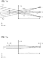
- Figures 1a, 1b are in different sectional planes only the relevant beam paths of partial beams TS_A, TS_B in the area of the mixing grating MG and several detector elements D1, D2, D3 shown.
- the Figures 2a - 2d serve to further explain the mixing grid MG.
- the measuring direction acts in the Figures 1a, 1b and 2a - 2d in each case the direction denoted by z.
- the moving objects can, for example, be machine parts, the relative position of which is to be determined.
- a scanning unit of the position measuring device can be connected to one of the two objects.
- the scanning unit here comprises various components such as a light source, several detector elements and one or more grids with different functions.
- a measuring reflector or a material measure of the position measuring device is connected to the other object.
- the position-dependent and phase-shifted incremental signals generated with the aid of the position measuring device according to the invention can be further processed, for example, by a machine control system in order to control the positioning of the corresponding machine parts.
- the diffraction order of the partial beam TS_A and the 1st diffraction order of the partial beam TS_B each emerge vertically from the mixing grating MG and then continue to propagate superimposed on one another in the direction of the centrally arranged detector element D2.
- the 0th order of diffraction of the partial beam TS_A and the +2 propagate.
- Diffraction order of the partial beam TS_B superimposed on one another to form the detector element D1; the 0th order of diffraction of the partial beam TS_B and the -2.
- Diffraction order of the partial beam TS_A propagate superimposed on one another to the detector element D3.
- the mixing grating MG consequently supplies at least a 0th order of diffraction and +/- 1st and +/- 2nd orders of diffraction of the partial beams TS_A, TS_B incident thereon in transmission.
- FIG Figure 2a A corresponding linear grating G M , designed as a four-stage transmission phase grating, which has the grating period d M , is shown in FIG Figure 2a shown in a schematic plan view.
- FIG. 2b A corresponding, rotationally symmetrical grating G L with the required focusing properties is shown in Figure 2b shown in a schematic plan view.
- the grating G L is also designed as a four-stage transmission phase grating. That is to say, four grating areas arranged one after the other are provided for each grating period in the radial direction, in which the partial beam bundles passing through each experience a different phase offset.
- the four phase different grating areas are also in Figure 2b shown differently according to the associated legend.
- FIG Figure 2c An exemplary embodiment of a mixing grating MG which is formed on the basis of the above considerations and at the same time has the required phase-shifting effects of the combining element and the focusing effect of the focusing element is shown in FIG Figure 2c shown schematically in a plan view.
- the mixing grating MG shown is designed as a multi-stage - specifically: four-stage - transmission phase grating, the four differently shown grating areas in the figure having different phase-shifting effects on the partial beams passing through.
- FIG. 2d a sectional view through the mixing grid from FIG. 3c along the indicated x-direction is shown.
- the four phase stages provided and the phase profile of the mixing grating MG provided along the x direction are clearly evident here.
- the first grid areas with a step height h there are further grid areas which each have step heights 2h, 3h and 4h.
- the mixing grid as a stepless grid or as a sawtooth grid.
- FIG Figure 3 A first specific exemplary embodiment of an optical position measuring device according to the invention, in which a diffractive mixing grating with the optical functionalities explained above is used, is shown in FIG Figure 3 shown in a schematic sectional side view.
- This position measuring device is used to detect the distance between two objects, not shown, which are connected to the measuring reflector 110 and the scanning unit 120 and which are arranged to be displaceable relative to one another along the vertical measuring direction z.
- the measuring reflector 110 consists of a carrier substrate 112 on which a plane mirror 114 is arranged. As can be seen from the figure, the reflecting side of the plane mirror 114 is oriented in the direction of the scanning unit 120.
- a light source 121 On the side of the scanning unit 120, a light source 121, a detector arrangement 125 with a plurality of optoelectronic detector elements and a transparent carrier body 137, for example made of glass, are provided; alternatively, a suitable hollow body could also be used as the carrier body.
- a suitable hollow body could also be used as the carrier body.
- FIG Figure 3 a truncated pyramidal cross-section.
- the support body 137 optically-functionally relevant elements arranged. These elements include a splitting element 132 arranged on the surface of the carrier body 137 facing the measuring reflector 110 and a mixing grid 135 as well as four deflecting elements 133a, 133b, 134a, 134b arranged on the carrier body side surfaces.
- a first deflecting element 133a and a second deflecting element 133b are arranged on the left side surface of the carrier body 137, and a third deflecting element 134a and a fourth deflecting element 134b are arranged on the right side surface of the carrier body 137.
- the splitting element 132 like the mixing grating 135, is designed as a transmission grating; in this exemplary embodiment, reflection grids with appropriately selected grating periods, whose reflective surfaces are oriented towards the interior of the carrier body 137, function as deflecting elements 133a, 133b, 134a, 134b.
- the bundle of rays emitted by the light source 121 first passes through an optically ineffective region 131 on that side of the carrier body 137 which faces the light source 121. After passing through the carrier body 137, the bundle of rays reaches the splitting element 132 and is split into two partial bundles of rays Figure 3 can be seen in the yz plane in the direction of the measuring reflector 110 and act on it a first time at the first impact locations.
- the partial beams are reflected back in the direction of the scanning unit 120, specifically in the direction of the first and second deflecting elements 133a, 133b.
- the partial beams of rays are then deflected by these deflecting elements 133a, 133b in the direction of the third and fourth deflecting elements 134a, 134b.
- the third and fourth deflecting elements 134a, 134b are then used to redirect the partial beams in the direction of the plane mirror 114 of the measuring reflector 110, which the partial beams then impinge on a second time at second points of incidence.
- the second impact locations on the plane mirror 114 can be compared to the first The points of incidence of the partial beams must be offset in the specified x-direction. From the second incidence locations 114, the partial beams are finally reflected back onto the mixing grating 135, which is designed as explained above and has the mentioned optical functionalities.
- the mixing grid 135 From the mixing grid 135, three pairs of superimposed, interfering partial beams then propagate through the carrier body 137, leave it through the optically ineffective area 136 and, due to the optical effect of the mixing grid 135, reach the three intended detector elements of the detector arrangement 125 in a focused manner optical functionalities of the mixing grating 135 with regard to phase-shifting and focusing effect, the mixing grating 135 in the present case also has a deflecting effect perpendicular to the plane of the drawing, ie the three pairs of partial beams propagate inclined with respect to the xz plane in the direction of the detector elements 125 125, a plurality of phase-shifted, position-dependent incremental signals with regard to the relative offset of measuring reflector 110 and scanning unit 120 along the measuring direction z can be detected.
- FIG. 4a and 4b A second embodiment of the position measuring device according to the invention is shown in two different sectional views in Figures 4a and 4b shown in schematic form.
- This exemplary embodiment of a position measuring device according to the invention serves to detect the relative movement of a material measure 210 and a scanning unit 220 along the measuring direction x; As can be seen from the figures, the measuring direction x is oriented vertically in this example. Two objects, which are movably arranged at least along the measuring direction x and are not shown in the figures, are in turn connected to the material measure 210 and the scanning unit 220.
- the material measure 210 consists of a reflection phase grating 214 which extends along the measuring direction x and which is arranged on a carrier substrate 212.
- the reflection phase grating 214 here comprises periodically arranged along the measuring direction x, Rectangular graduation areas with different phase-shifting effects on the incident beams.
- a light source 221, a plurality of optoelectronic detector elements 225 and a transparent scanning plate 237 with a plurality of optically function-relevant elements arranged thereon are provided. These include a plurality of scanning grids 233 arranged on the underside of scanning plate 237 and a mixing grating 235 arranged on the upper side.
- the underside here denotes that side of scanning plate 237 which faces measuring standard 10; the top of the scanning plate 237 is accordingly oriented away from the measuring standard 210.
- the scanning grating 233 and the mixing grating 235 are each designed as a transmission phase grating.
- the beam emitted by the light source 221 passes through the scanning plate 237 without further deflection or splitting and arrives at the top of the measuring standard 210, where the reflection phase grating is arranged. There, the incident beam is split into reflected partial beams of +/- 1st diffraction order, which then propagate back in the direction of the scanning unit 210 or the scanning plate 237.
- the angle of diffraction of the reflected partial beams to the measuring standard normal is identical in terms of amount to the angle of incidence to the measuring normal; the measuring standard 210 is thus illuminated in this variant at the so-called Littrow angle.
- the reflected partial beams then hit the scanning grids 233 on the underside of the scanning plate 237.
- the mixing grating 235 on the one hand, certain diffraction orders are superimposed in pairs, which are then in the direction of the further propagate downstream detector elements 225.
- the mixing grating 235 also takes over the focusing of the pairs of partial beams onto the individual detector elements 225.
- the correspondingly designed mixing grid 235 despite the large beam diameter on the measuring standard 210, an only small spot diameter on the detector elements 225 can be ensured.
- the large beam diameter on the material measure 210 ensured good insensitivity of the scanning to contamination that may occur on the material measure 210.
- the use of small detector elements is possible, which ensures only a low level of signal noise in the incremental signals generated.
- This exemplary embodiment of a position measuring device also serves, like the previous exemplary embodiment, to detect the relative movement of two movable objects along a vertical measuring direction, which in the Figures 5a, 5b is again denoted by x.
- the material measure 310 is formed here, which in turn consists of a reflection phase grating 314 which extends along the measuring direction x and which is arranged on a carrier substrate 312.
- a light source 321, several detector elements 325 and a transparent scanning plate 337 with several optically function-relevant elements arranged thereon are provided.
- several grids arranged on the underside of the scanning plate 237 namely a splitting grating 331, several scanning grids 333.1-333.4 and a mixing grating 335; these gratings are each designed as a transmission phase grating.
- two reflector elements 336, 338 are arranged, the reflective side of which is oriented in the direction of the measuring standard 310.
- the beam emitted by the light source 321 first passes through the scanning plate 337 until it reaches the splitting grating 331 arranged on the underside. There results a splitting into two partial beams, which then propagate further in the direction of the measuring standard 310. A back reflection takes place from the reflection phase grating 314 of the material measure 310 in the direction of the scanning unit 310. There the partial beams then pass through the scanning grids 333.2, 333.4, via which a deflection in the -y direction and a focusing on the reflector elements 336, 338 on the scanning plate Top results. The partial beam bundles are then reflected back to further scanning gratings 333.1, 333.3 on the underside of the scanning plate 337 by the reflector elements 336, 338.
- the partial beams are then collimated and deflected again via these scanning grids 333.1, 333.2, so that they finally impinge on the material measure 310 perpendicularly one more time in the xz plane.
- the partial beams then reached the mixing grating 335 on the underside of the scanning plate 337, which then exerts the optical effects already explained above on the partial beams. Pairs of interfering partial beams then propagate in a focused manner on the downstream detector elements 325 via which the phase-shifted incremental signals are generated.
- scanning beam paths can also be provided in the position measuring device according to the invention, in which those to be superimposed Partial beams do not fall on the mixing grating at symmetrical angles of incidence, as was initially shown in FIG Figures 1a, 1b was intended.
- a mixed grating can also be formed for such variants in the manner explained, which, in addition to setting defined phase relationships for the various partial beams, also ensures focusing on the detector elements.
- the position measuring device according to the invention is used not only for detecting displacement movements along linear measuring directions; Position measuring devices can also be designed that detect relative rotational movements of two objects, etc.
Landscapes
- Physics & Mathematics (AREA)
- General Physics & Mathematics (AREA)
- Optical Transform (AREA)
- Length Measuring Devices By Optical Means (AREA)
Claims (9)
- Dispositif optique de mesure de position pour la détermination interférentielle de la distance relative de deux objets qui sont mobiles l'un par rapport à l'autre le long d'au moins une direction de mesure, dans lequel un faisceau de rayons émis par une source de lumière est divisé en au moins deux faisceaux de rayons partiels qui sollicitent ensuite une ou plusieurs grilles sur des trajectoires de rayon séparées et subissent alors des déphasages en fonction de la distance,
caractérisé en ce que- les faisceaux de rayons partiels (TS_A, TS_B) sont superposés au niveau d'une grille d'injection (MG ; 135 ; 235 ; 335) et propagent ensuite au moins trois paires de faisceaux de rayons partiels (TS_A, TS_B) en interférence dans différentes directions spatiales, dans lequel la grille d'injection (MG ; 135 ; 235 ; 335) permet en outre d'effectuer une focalisation de chaque paire avec des faisceaux de rayons partiels (TS_A, TS_B) en interférence sur un élément de détecteur (D1, D2, D3 ; 125 ; 225 ; 325) de sorte que les éléments de détecteur (D1, D2, D3 ; 125 ; 225 ; 325) permettent de détecter au moins trois signaux incrémentaux déphasés, dépendants de la position, et- la grille d'injection (MG ; 135 ; 235 ; 335) est réalisée comme un réseau de phase à transmission à n niveaux : h := hauteur de niveauλ := longueur d'onde de la lumièren := 2, 3, 4, ...n1 := indice de réfraction des ondulations de: réseaun2 := indice de réfraction des lacunes de réseau.
 - Dispositif optique de mesure de position selon la revendication 1, caractérisé en ce que deux faisceaux de rayons partiels (TS_A, TS_B) incidents sur la grille d'injection (MG ; 135 ; 235 ; 335) subissent au moins une diffraction de l'ordre de diffraction 0, +/-1 et +/-2, et des faisceaux de rayons partiels en interférence par paires, de l'ordre de diffraction 0/-2, de l'ordre de diffraction +1/-1 et de l'ordre de diffraction 0/+2 se propagent en direction des éléments de détecteur (D1, D2, D3 ; 125 ; 225 ; 325).
- Dispositif optique de mesure de position selon la revendication 1, caractérisé en ce que la grille d'injection (MG ; 135 ; 235 ; 335) est réalisée comme un réseau de phase à transmission à n niveaux qui possède une fonction de phase ϕ(x, y) selon
 ϕ(x, y) := la fonction de phase du réseau de phase à transmissionx, y := les coordonnées géométriques dans le plan du réseau de phase à transmissionn := 2, 3, 4, ... ; le nombre des niveaux du réseau de phase à transmissionT(x, y) := la fonction de transmission de la grille d'injection.
 - Dispositif optique de mesure de position selon au moins l'une des revendications précédentes, caractérisé en ce que- l'un des deux objets est relié à un réflecteur de mesure plan (110),- l'autre objet est relié à une unité de palpage (120) et est disposé le long d'une direction de mesure (z) de manière mobile par rapport au réflecteur de mesure (110), la direction de mesure (z) étant orientée perpendiculairement au réflecteur de mesure (110), et- dans lequel l'unité de palpage (120) présente les composants suivants :- au moins une source de lumière (121),- plusieurs éléments de détecteur (125),- la grille d'injection (135),- plusieurs éléments de déviation (133a, 133b, 134a, 134b) qui sont réalisés respectivement sous la forme d'un réseau à réflexion unidimensionnel, et- au moins un élément de division (132) qui est réalisé comme un réseau à transmission unidimensionnel.
- Dispositif selon la revendication 4, caractérisé en ce que l'unité de palpage (120) présente un corps de support transparent (137) ayant une section transversale en forme de pyramide tronquée sur la surface duquel, tournée vers le réflecteur de mesure (110), est disposé l'élément de division (132), et sur les surfaces latérales duquel sont disposés les au moins quatre éléments de déviation (133a, 133b, 134a, 134b).
- Dispositif selon la revendication 4, caractérisé en ce que les différents composants sont réalisés et disposés de telle sorte que- le faisceau de rayons émis par la source de lumière (121) subit au niveau de l'élément de division (132) une division en deux faisceaux de rayons partiels, et les deux faisceaux de rayons partiels se propagent en direction du réflecteur de mesure (110),- une rétroréflexion des faisceaux de rayons partiels a lieu à partir du réflecteur de mesure (110) dans la direction du premier et du deuxième élément de déviation (133a, 133b) dans l'unité de palpage (120), où il en résulte une déviation des faisceaux de rayons partiels dans la direction du troisième et du quatrième élément de déviation (134a, 134b), et- le troisième et le quatrième élément de déviation (134a, 134b) effectuent une déviation des faisceaux de rayons partiels vers le réflecteur de mesure (110),- d'où il résulte une rétroréflexion des faisceaux de rayons partiels en direction de la grille d'injection (135) dans l'unité de palpage (120), au niveau de laquelle une superposition des faisceaux de rayons partiels a lieu, et ensuite, trois paires de faisceaux de rayons partiels en interférence sont focalisées dans différentes directions spatiales sur trois éléments de détecteur (125).
- Dispositif optique de mesure de position selon au moins l'une des revendications 1 à 3, caractérisé en ce que- l'un des deux objets est relié à un étalon (210 ; 310),- l'autre objet est relié à une unité de palpage (220 ; 320) et disposé le long d'une direction de mesure (x) de manière mobile par rapport à l'étalon (210 ; 310), la direction de mesure (x) étant orientée en parallèle au plan d'étalon, et- dans lequel l'unité de palpage (220 ; 320) présente les composants suivants :- au moins une source de lumière 221 ; 321,- plusieurs éléments de détecteur (225 ; 325),- la grille d'injection (235 ; 335),- plusieurs réseaux de palpage (233 ; 333.1, 333.2, 333.3, 333.4) qui sont respectivement réalisés sous forme de réseau à transmission unidimensionnel.
- Dispositif optique de mesure de position selon la revendication 7, caractérisé en ce que l'unité de palpage (220 ; 320) présente en outre une plaque de palpage transparente (237 ; 337) sur la face supérieure et/ou inférieure de laquelle sont disposées la grille d'injection (235 ; 335) et/ou les réseaux de palpage (233 ; 333.1, 333.2, 333.3, 333.4).
- Dispositif optique de mesure de position selon la revendication 8, caractérisé en ce que sur la surface supérieure de la plaque de palpage (337), un ou plusieurs éléments de réflecteur (336, 338) sont disposés dont la face réfléchissante est respectivement orientée en direction de l'étalon (310) et sur la face inférieure, la grille d'injection (335) ainsi que les grilles de palpage (333.1, 333.2, 333.3, 333.4) sont disposées.
Applications Claiming Priority (1)
| Application Number | Priority Date | Filing Date | Title |
|---|---|---|---|
| DE102018212719.0A DE102018212719A1 (de) | 2018-07-31 | 2018-07-31 | Optische Positionsmesseinrichtung |
Publications (2)
| Publication Number | Publication Date |
|---|---|
| EP3605026A1 EP3605026A1 (fr) | 2020-02-05 |
| EP3605026B1 true EP3605026B1 (fr) | 2020-11-18 |
Family
ID=67402859
Family Applications (1)
| Application Number | Title | Priority Date | Filing Date |
|---|---|---|---|
| EP19186786.0A Active EP3605026B1 (fr) | 2018-07-31 | 2019-07-17 | Dispositif optique de mesure de position |
Country Status (5)
| Country | Link |
|---|---|
| US (1) | US10823550B2 (fr) |
| EP (1) | EP3605026B1 (fr) |
| JP (1) | JP7201547B2 (fr) |
| CN (1) | CN110779447B (fr) |
| DE (1) | DE102018212719A1 (fr) |
Families Citing this family (1)
| Publication number | Priority date | Publication date | Assignee | Title |
|---|---|---|---|---|
| JP7513510B2 (ja) | 2020-11-24 | 2024-07-09 | 株式会社ミツトヨ | 変位センサ及び形状測定装置 |
Family Cites Families (12)
| Publication number | Priority date | Publication date | Assignee | Title |
|---|---|---|---|---|
| GB1400253A (en) * | 1972-03-17 | 1975-07-16 | Ti Group Services Ltd | Gauging dimensions |
| GB8413955D0 (en) | 1984-05-31 | 1984-07-04 | Pa Consulting Services | Displacement measuring apparatus |
| JPH09284684A (ja) * | 1996-04-17 | 1997-10-31 | Hitachi Ltd | 単板式カラー液晶ディスプレイ装置 |
| DE59912617D1 (de) * | 1998-08-01 | 2006-02-16 | Heidenhain Gmbh Dr Johannes | Rotatorische Positionsmesseinrichtung |
| DE102006042743A1 (de) * | 2006-09-12 | 2008-03-27 | Dr. Johannes Heidenhain Gmbh | Positionsmesseinrichtung |
| DE102008007319A1 (de) * | 2008-02-02 | 2009-08-06 | Dr. Johannes Heidenhain Gmbh | Optische Positionsmesseinrichtung |
| DE102011082156A1 (de) * | 2010-12-16 | 2012-06-21 | Dr. Johannes Heidenhain Gmbh | Optische Positionsmesseinrichtung |
| DE102012222077A1 (de) * | 2012-12-03 | 2014-06-05 | Dr. Johannes Heidenhain Gmbh | Positionsmesseinrichtung |
| DE102013222383A1 (de) * | 2013-02-06 | 2014-08-07 | Dr. Johannes Heidenhain Gmbh | Optische Positionsmesseinrichtung |
| DE102013206693A1 (de) | 2013-04-15 | 2014-10-16 | Dr. Johannes Heidenhain Gmbh | Vorrichtung zur interferentiellen Abstandsmessung |
| JP6696748B2 (ja) * | 2014-10-21 | 2020-05-20 | ドクトル・ヨハネス・ハイデンハイン・ゲゼルシヤフト・ミツト・ベシユレンクテル・ハフツングDr. Johannes Heidenhain Gesellschaft Mit Beschrankter Haftung | 光学式エンコーダ |
| CN104729411B (zh) * | 2015-03-10 | 2017-07-14 | 中国科学院上海光学精密机械研究所 | 基于高密度光栅的高分辨率光栅干涉仪 |
-
2018
- 2018-07-31 DE DE102018212719.0A patent/DE102018212719A1/de not_active Withdrawn
-
2019
- 2019-07-11 JP JP2019129096A patent/JP7201547B2/ja active Active
- 2019-07-17 EP EP19186786.0A patent/EP3605026B1/fr active Active
- 2019-07-25 US US16/522,037 patent/US10823550B2/en active Active
- 2019-07-31 CN CN201910699725.7A patent/CN110779447B/zh active Active
Non-Patent Citations (1)
| Title |
|---|
| None * |
Also Published As
| Publication number | Publication date |
|---|---|
| CN110779447B (zh) | 2023-08-22 |
| US20200041252A1 (en) | 2020-02-06 |
| JP7201547B2 (ja) | 2023-01-10 |
| CN110779447A (zh) | 2020-02-11 |
| US10823550B2 (en) | 2020-11-03 |
| JP2020020788A (ja) | 2020-02-06 |
| DE102018212719A1 (de) | 2020-02-20 |
| EP3605026A1 (fr) | 2020-02-05 |
Similar Documents
| Publication | Publication Date | Title |
|---|---|---|
| EP2149036B1 (fr) | Dispositif de mesure de position optique | |
| EP1739395B1 (fr) | Dispositif de mesure de position | |
| DE19748802B4 (de) | Optische Positionsmeßeinrichtung | |
| DE102013004869B4 (de) | Verfahren zur Ausbildung einer Strukturierung an Oberflächen von Bauteilen mit einem Laserstrahl | |
| EP1923672B1 (fr) | Dispositif de mesure de position | |
| EP2388558B1 (fr) | Dispositif optique de mesure de la position | |
| DE102008007319A1 (de) | Optische Positionsmesseinrichtung | |
| EP2450673B1 (fr) | Dispositif optique de mesure de la position | |
| EP3258220B1 (fr) | Dispositif optique de mesure de position | |
| DE102005036180B4 (de) | Optische Positionsmesseinrichtung | |
| EP3059554B1 (fr) | Dispositif optique de mesure de position | |
| EP2980525A1 (fr) | Interféromètre à double passage | |
| EP3605026B1 (fr) | Dispositif optique de mesure de position | |
| EP1992915B1 (fr) | Dispositif de mesure de position | |
| EP2869034B1 (fr) | Dispositif de détermination de la position | |
| DE102011005937B4 (de) | Vorrichtung zur interferentiellen Abstandsmessung | |
| DE2852497C2 (de) | Scanner mit einer mit Lichtstrahl arbeitenden Aufzeichnungseinrichtung | |
| DE102019108681A1 (de) | Vorrichtung und Verfahren zur Erzeugung eines Doppel- oder Vielfachspots in der Lasermaterialbearbeitung | |
| EP3835727B1 (fr) | Dispositif optique de mesure de position | |
| DE112014001977B4 (de) | Vorrichtung zur interferentiellen Abstandsmessung | |
| EP3936830B1 (fr) | Dispositif optique de mesure de la position | |
| DE10160472A1 (de) | Röntgen-optisches System und Verfahren zur Abbildung einer Quelle | |
| EP4143502A1 (fr) | Système de microscope et procédé de mesure d'une structure de surface d'un échantillon, et élément optique diffractif | |
| DE102008046793A1 (de) | Optische Positionsmesseinrichtung | |
| WO2002029828A1 (fr) | Procede et dispositif permettant d'agir sur des rayons x |
Legal Events
| Date | Code | Title | Description |
|---|---|---|---|
| PUAI | Public reference made under article 153(3) epc to a published international application that has entered the european phase |
Free format text: ORIGINAL CODE: 0009012 |
|
| STAA | Information on the status of an ep patent application or granted ep patent |
Free format text: STATUS: REQUEST FOR EXAMINATION WAS MADE |
|
| STAA | Information on the status of an ep patent application or granted ep patent |
Free format text: STATUS: EXAMINATION IS IN PROGRESS |
|
| 17P | Request for examination filed |
Effective date: 20190717 |
|
| AK | Designated contracting states |
Kind code of ref document: A1 Designated state(s): AL AT BE BG CH CY CZ DE DK EE ES FI FR GB GR HR HU IE IS IT LI LT LU LV MC MK MT NL NO PL PT RO RS SE SI SK SM TR |
|
| AX | Request for extension of the european patent |
Extension state: BA ME |
|
| 17Q | First examination report despatched |
Effective date: 20200110 |
|
| GRAP | Despatch of communication of intention to grant a patent |
Free format text: ORIGINAL CODE: EPIDOSNIGR1 |
|
| STAA | Information on the status of an ep patent application or granted ep patent |
Free format text: STATUS: GRANT OF PATENT IS INTENDED |
|
| RIC1 | Information provided on ipc code assigned before grant |
Ipc: G01D 5/38 20060101AFI20200508BHEP |
|
| INTG | Intention to grant announced |
Effective date: 20200603 |
|
| RBV | Designated contracting states (corrected) |
Designated state(s): AL AT BE BG CH CY CZ DE DK EE ES FI FR GB GR HR HU IE IS IT LI LT LU LV MC MK MT NL NO PL PT RO RS SE SI SK SM TR |
|
| GRAS | Grant fee paid |
Free format text: ORIGINAL CODE: EPIDOSNIGR3 |
|
| GRAA | (expected) grant |
Free format text: ORIGINAL CODE: 0009210 |
|
| STAA | Information on the status of an ep patent application or granted ep patent |
Free format text: STATUS: THE PATENT HAS BEEN GRANTED |
|
| AK | Designated contracting states |
Kind code of ref document: B1 Designated state(s): AL AT BE BG CH CY CZ DE DK EE ES FI FR GB GR HR HU IE IS IT LI LT LU LV MC MK MT NL NO PL PT RO RS SE SI SK SM TR |
|
| REG | Reference to a national code |
Ref country code: GB Ref legal event code: FG4D Free format text: NOT ENGLISH |
|
| REG | Reference to a national code |
Ref country code: CH Ref legal event code: EP |
|
| REG | Reference to a national code |
Ref country code: IE Ref legal event code: FG4D Free format text: LANGUAGE OF EP DOCUMENT: GERMAN |
|
| REG | Reference to a national code |
Ref country code: DE Ref legal event code: R096 Ref document number: 502019000421 Country of ref document: DE |
|
| REG | Reference to a national code |
Ref country code: CH Ref legal event code: NV Representative=s name: ICB INGENIEURS CONSEILS EN BREVETS SA, CH Ref country code: AT Ref legal event code: REF Ref document number: 1336254 Country of ref document: AT Kind code of ref document: T Effective date: 20201215 |
|
| REG | Reference to a national code |
Ref country code: NL Ref legal event code: FP |
|
| PG25 | Lapsed in a contracting state [announced via postgrant information from national office to epo] |
Ref country code: PT Free format text: LAPSE BECAUSE OF FAILURE TO SUBMIT A TRANSLATION OF THE DESCRIPTION OR TO PAY THE FEE WITHIN THE PRESCRIBED TIME-LIMIT Effective date: 20210318 Ref country code: RS Free format text: LAPSE BECAUSE OF FAILURE TO SUBMIT A TRANSLATION OF THE DESCRIPTION OR TO PAY THE FEE WITHIN THE PRESCRIBED TIME-LIMIT Effective date: 20201118 Ref country code: FI Free format text: LAPSE BECAUSE OF FAILURE TO SUBMIT A TRANSLATION OF THE DESCRIPTION OR TO PAY THE FEE WITHIN THE PRESCRIBED TIME-LIMIT Effective date: 20201118 Ref country code: NO Free format text: LAPSE BECAUSE OF FAILURE TO SUBMIT A TRANSLATION OF THE DESCRIPTION OR TO PAY THE FEE WITHIN THE PRESCRIBED TIME-LIMIT Effective date: 20210218 Ref country code: GR Free format text: LAPSE BECAUSE OF FAILURE TO SUBMIT A TRANSLATION OF THE DESCRIPTION OR TO PAY THE FEE WITHIN THE PRESCRIBED TIME-LIMIT Effective date: 20210219 |
|
| PG25 | Lapsed in a contracting state [announced via postgrant information from national office to epo] |
Ref country code: SE Free format text: LAPSE BECAUSE OF FAILURE TO SUBMIT A TRANSLATION OF THE DESCRIPTION OR TO PAY THE FEE WITHIN THE PRESCRIBED TIME-LIMIT Effective date: 20201118 Ref country code: PL Free format text: LAPSE BECAUSE OF FAILURE TO SUBMIT A TRANSLATION OF THE DESCRIPTION OR TO PAY THE FEE WITHIN THE PRESCRIBED TIME-LIMIT Effective date: 20201118 Ref country code: LV Free format text: LAPSE BECAUSE OF FAILURE TO SUBMIT A TRANSLATION OF THE DESCRIPTION OR TO PAY THE FEE WITHIN THE PRESCRIBED TIME-LIMIT Effective date: 20201118 Ref country code: IS Free format text: LAPSE BECAUSE OF FAILURE TO SUBMIT A TRANSLATION OF THE DESCRIPTION OR TO PAY THE FEE WITHIN THE PRESCRIBED TIME-LIMIT Effective date: 20210318 Ref country code: BG Free format text: LAPSE BECAUSE OF FAILURE TO SUBMIT A TRANSLATION OF THE DESCRIPTION OR TO PAY THE FEE WITHIN THE PRESCRIBED TIME-LIMIT Effective date: 20210218 |
|
| REG | Reference to a national code |
Ref country code: LT Ref legal event code: MG9D |
|
| PG25 | Lapsed in a contracting state [announced via postgrant information from national office to epo] |
Ref country code: HR Free format text: LAPSE BECAUSE OF FAILURE TO SUBMIT A TRANSLATION OF THE DESCRIPTION OR TO PAY THE FEE WITHIN THE PRESCRIBED TIME-LIMIT Effective date: 20201118 |
|
| PG25 | Lapsed in a contracting state [announced via postgrant information from national office to epo] |
Ref country code: LT Free format text: LAPSE BECAUSE OF FAILURE TO SUBMIT A TRANSLATION OF THE DESCRIPTION OR TO PAY THE FEE WITHIN THE PRESCRIBED TIME-LIMIT Effective date: 20201118 Ref country code: RO Free format text: LAPSE BECAUSE OF FAILURE TO SUBMIT A TRANSLATION OF THE DESCRIPTION OR TO PAY THE FEE WITHIN THE PRESCRIBED TIME-LIMIT Effective date: 20201118 Ref country code: CZ Free format text: LAPSE BECAUSE OF FAILURE TO SUBMIT A TRANSLATION OF THE DESCRIPTION OR TO PAY THE FEE WITHIN THE PRESCRIBED TIME-LIMIT Effective date: 20201118 Ref country code: EE Free format text: LAPSE BECAUSE OF FAILURE TO SUBMIT A TRANSLATION OF THE DESCRIPTION OR TO PAY THE FEE WITHIN THE PRESCRIBED TIME-LIMIT Effective date: 20201118 Ref country code: SM Free format text: LAPSE BECAUSE OF FAILURE TO SUBMIT A TRANSLATION OF THE DESCRIPTION OR TO PAY THE FEE WITHIN THE PRESCRIBED TIME-LIMIT Effective date: 20201118 Ref country code: SK Free format text: LAPSE BECAUSE OF FAILURE TO SUBMIT A TRANSLATION OF THE DESCRIPTION OR TO PAY THE FEE WITHIN THE PRESCRIBED TIME-LIMIT Effective date: 20201118 |
|
| REG | Reference to a national code |
Ref country code: DE Ref legal event code: R097 Ref document number: 502019000421 Country of ref document: DE |
|
| PG25 | Lapsed in a contracting state [announced via postgrant information from national office to epo] |
Ref country code: DK Free format text: LAPSE BECAUSE OF FAILURE TO SUBMIT A TRANSLATION OF THE DESCRIPTION OR TO PAY THE FEE WITHIN THE PRESCRIBED TIME-LIMIT Effective date: 20201118 |
|
| PLBE | No opposition filed within time limit |
Free format text: ORIGINAL CODE: 0009261 |
|
| STAA | Information on the status of an ep patent application or granted ep patent |
Free format text: STATUS: NO OPPOSITION FILED WITHIN TIME LIMIT |
|
| 26N | No opposition filed |
Effective date: 20210819 |
|
| PG25 | Lapsed in a contracting state [announced via postgrant information from national office to epo] |
Ref country code: AL Free format text: LAPSE BECAUSE OF FAILURE TO SUBMIT A TRANSLATION OF THE DESCRIPTION OR TO PAY THE FEE WITHIN THE PRESCRIBED TIME-LIMIT Effective date: 20201118 Ref country code: IT Free format text: LAPSE BECAUSE OF FAILURE TO SUBMIT A TRANSLATION OF THE DESCRIPTION OR TO PAY THE FEE WITHIN THE PRESCRIBED TIME-LIMIT Effective date: 20201118 |
|
| PG25 | Lapsed in a contracting state [announced via postgrant information from national office to epo] |
Ref country code: SI Free format text: LAPSE BECAUSE OF FAILURE TO SUBMIT A TRANSLATION OF THE DESCRIPTION OR TO PAY THE FEE WITHIN THE PRESCRIBED TIME-LIMIT Effective date: 20201118 |
|
| PG25 | Lapsed in a contracting state [announced via postgrant information from national office to epo] |
Ref country code: ES Free format text: LAPSE BECAUSE OF FAILURE TO SUBMIT A TRANSLATION OF THE DESCRIPTION OR TO PAY THE FEE WITHIN THE PRESCRIBED TIME-LIMIT Effective date: 20201118 |
|
| PG25 | Lapsed in a contracting state [announced via postgrant information from national office to epo] |
Ref country code: MC Free format text: LAPSE BECAUSE OF FAILURE TO SUBMIT A TRANSLATION OF THE DESCRIPTION OR TO PAY THE FEE WITHIN THE PRESCRIBED TIME-LIMIT Effective date: 20201118 |
|
| REG | Reference to a national code |
Ref country code: BE Ref legal event code: MM Effective date: 20210731 |
|
| PG25 | Lapsed in a contracting state [announced via postgrant information from national office to epo] |
Ref country code: IS Free format text: LAPSE BECAUSE OF FAILURE TO SUBMIT A TRANSLATION OF THE DESCRIPTION OR TO PAY THE FEE WITHIN THE PRESCRIBED TIME-LIMIT Effective date: 20210318 Ref country code: LU Free format text: LAPSE BECAUSE OF NON-PAYMENT OF DUE FEES Effective date: 20210717 Ref country code: FR Free format text: LAPSE BECAUSE OF NON-PAYMENT OF DUE FEES Effective date: 20210731 |
|
| PG25 | Lapsed in a contracting state [announced via postgrant information from national office to epo] |
Ref country code: IE Free format text: LAPSE BECAUSE OF NON-PAYMENT OF DUE FEES Effective date: 20210717 Ref country code: BE Free format text: LAPSE BECAUSE OF NON-PAYMENT OF DUE FEES Effective date: 20210731 |
|
| PG25 | Lapsed in a contracting state [announced via postgrant information from national office to epo] |
Ref country code: CY Free format text: LAPSE BECAUSE OF FAILURE TO SUBMIT A TRANSLATION OF THE DESCRIPTION OR TO PAY THE FEE WITHIN THE PRESCRIBED TIME-LIMIT Effective date: 20201118 |
|
| PG25 | Lapsed in a contracting state [announced via postgrant information from national office to epo] |
Ref country code: HU Free format text: LAPSE BECAUSE OF FAILURE TO SUBMIT A TRANSLATION OF THE DESCRIPTION OR TO PAY THE FEE WITHIN THE PRESCRIBED TIME-LIMIT; INVALID AB INITIO Effective date: 20190717 |
|
| PGFP | Annual fee paid to national office [announced via postgrant information from national office to epo] |
Ref country code: GB Payment date: 20230721 Year of fee payment: 5 Ref country code: CH Payment date: 20230801 Year of fee payment: 5 |
|
| PGFP | Annual fee paid to national office [announced via postgrant information from national office to epo] |
Ref country code: DE Payment date: 20230719 Year of fee payment: 5 |
|
| PG25 | Lapsed in a contracting state [announced via postgrant information from national office to epo] |
Ref country code: MK Free format text: LAPSE BECAUSE OF FAILURE TO SUBMIT A TRANSLATION OF THE DESCRIPTION OR TO PAY THE FEE WITHIN THE PRESCRIBED TIME-LIMIT Effective date: 20201118 |
|
| PGFP | Annual fee paid to national office [announced via postgrant information from national office to epo] |
Ref country code: NL Payment date: 20240719 Year of fee payment: 6 |