EP3605026B1 - Optical positioning device - Google Patents
Optical positioning device Download PDFInfo
- Publication number
- EP3605026B1 EP3605026B1 EP19186786.0A EP19186786A EP3605026B1 EP 3605026 B1 EP3605026 B1 EP 3605026B1 EP 19186786 A EP19186786 A EP 19186786A EP 3605026 B1 EP3605026 B1 EP 3605026B1
- Authority
- EP
- European Patent Office
- Prior art keywords
- grating
- partial beams
- mixing
- scanning
- measuring device
- Prior art date
- Legal status (The legal status is an assumption and is not a legal conclusion. Google has not performed a legal analysis and makes no representation as to the accuracy of the status listed.)
- Active
Links
- 230000003287 optical effect Effects 0.000 title claims description 30
- 230000005540 biological transmission Effects 0.000 claims description 44
- 230000002452 interceptive effect Effects 0.000 claims description 17
- 239000000463 material Substances 0.000 claims description 15
- 230000001419 dependent effect Effects 0.000 claims description 10
- 230000010363 phase shift Effects 0.000 claims description 6
- 238000000034 method Methods 0.000 claims description 2
- 230000008569 process Effects 0.000 claims description 2
- 238000005259 measurement Methods 0.000 claims 1
- 230000000694 effects Effects 0.000 description 10
- 230000009021 linear effect Effects 0.000 description 6
- 238000001514 detection method Methods 0.000 description 3
- 230000009467 reduction Effects 0.000 description 3
- 239000000758 substrate Substances 0.000 description 3
- 238000006073 displacement reaction Methods 0.000 description 2
- 230000005693 optoelectronics Effects 0.000 description 2
- 230000006978 adaptation Effects 0.000 description 1
- XAGFODPZIPBFFR-UHFFFAOYSA-N aluminium Chemical compound [Al] XAGFODPZIPBFFR-UHFFFAOYSA-N 0.000 description 1
- 229910052782 aluminium Inorganic materials 0.000 description 1
- 230000015572 biosynthetic process Effects 0.000 description 1
- 238000011109 contamination Methods 0.000 description 1
- 230000008878 coupling Effects 0.000 description 1
- 238000010168 coupling process Methods 0.000 description 1
- 238000005859 coupling reaction Methods 0.000 description 1
- 239000000835 fiber Substances 0.000 description 1
- 230000007274 generation of a signal involved in cell-cell signaling Effects 0.000 description 1
- 239000011521 glass Substances 0.000 description 1
- PCHJSUWPFVWCPO-UHFFFAOYSA-N gold Chemical compound [Au] PCHJSUWPFVWCPO-UHFFFAOYSA-N 0.000 description 1
- 229910052737 gold Inorganic materials 0.000 description 1
- 239000010931 gold Substances 0.000 description 1
- 238000003384 imaging method Methods 0.000 description 1
- 238000004519 manufacturing process Methods 0.000 description 1
- 239000013307 optical fiber Substances 0.000 description 1
- 230000001902 propagating effect Effects 0.000 description 1
Images


Classifications
-
- G—PHYSICS
- G01—MEASURING; TESTING
- G01D—MEASURING NOT SPECIALLY ADAPTED FOR A SPECIFIC VARIABLE; ARRANGEMENTS FOR MEASURING TWO OR MORE VARIABLES NOT COVERED IN A SINGLE OTHER SUBCLASS; TARIFF METERING APPARATUS; MEASURING OR TESTING NOT OTHERWISE PROVIDED FOR
- G01D5/00—Mechanical means for transferring the output of a sensing member; Means for converting the output of a sensing member to another variable where the form or nature of the sensing member does not constrain the means for converting; Transducers not specially adapted for a specific variable
- G01D5/26—Mechanical means for transferring the output of a sensing member; Means for converting the output of a sensing member to another variable where the form or nature of the sensing member does not constrain the means for converting; Transducers not specially adapted for a specific variable characterised by optical transfer means, i.e. using infrared, visible, or ultraviolet light
- G01D5/32—Mechanical means for transferring the output of a sensing member; Means for converting the output of a sensing member to another variable where the form or nature of the sensing member does not constrain the means for converting; Transducers not specially adapted for a specific variable characterised by optical transfer means, i.e. using infrared, visible, or ultraviolet light with attenuation or whole or partial obturation of beams of light
- G01D5/34—Mechanical means for transferring the output of a sensing member; Means for converting the output of a sensing member to another variable where the form or nature of the sensing member does not constrain the means for converting; Transducers not specially adapted for a specific variable characterised by optical transfer means, i.e. using infrared, visible, or ultraviolet light with attenuation or whole or partial obturation of beams of light the beams of light being detected by photocells
- G01D5/36—Forming the light into pulses
- G01D5/38—Forming the light into pulses by diffraction gratings
-
- G—PHYSICS
- G01—MEASURING; TESTING
- G01B—MEASURING LENGTH, THICKNESS OR SIMILAR LINEAR DIMENSIONS; MEASURING ANGLES; MEASURING AREAS; MEASURING IRREGULARITIES OF SURFACES OR CONTOURS
- G01B11/00—Measuring arrangements characterised by the use of optical techniques
- G01B11/14—Measuring arrangements characterised by the use of optical techniques for measuring distance or clearance between spaced objects or spaced apertures
-
- G—PHYSICS
- G01—MEASURING; TESTING
- G01B—MEASURING LENGTH, THICKNESS OR SIMILAR LINEAR DIMENSIONS; MEASURING ANGLES; MEASURING AREAS; MEASURING IRREGULARITIES OF SURFACES OR CONTOURS
- G01B11/00—Measuring arrangements characterised by the use of optical techniques
- G01B11/02—Measuring arrangements characterised by the use of optical techniques for measuring length, width or thickness
-
- G—PHYSICS
- G01—MEASURING; TESTING
- G01B—MEASURING LENGTH, THICKNESS OR SIMILAR LINEAR DIMENSIONS; MEASURING ANGLES; MEASURING AREAS; MEASURING IRREGULARITIES OF SURFACES OR CONTOURS
- G01B11/00—Measuring arrangements characterised by the use of optical techniques
-
- G—PHYSICS
- G01—MEASURING; TESTING
- G01B—MEASURING LENGTH, THICKNESS OR SIMILAR LINEAR DIMENSIONS; MEASURING ANGLES; MEASURING AREAS; MEASURING IRREGULARITIES OF SURFACES OR CONTOURS
- G01B9/00—Measuring instruments characterised by the use of optical techniques
- G01B9/02—Interferometers
- G01B9/02001—Interferometers characterised by controlling or generating intrinsic radiation properties
- G01B9/0201—Interferometers characterised by controlling or generating intrinsic radiation properties using temporal phase variation
Definitions
- the present invention relates to an optical position measuring device which is suitable for the highly precise determination of the relative position of two objects that are movable relative to one another.
- Optical position measuring devices are known from the prior art, which are designed as so-called 3-grid measuring systems. These are used for the interferential determination of the relative distance between two objects that are movable to one another along at least one measuring direction.
- Partial beams which are split up from a beam emitted by a light source, pass through separate beam paths and act on one or more grids. The partial bundles of rays experience distance-dependent phase shifts before they come to an interfering superposition on a combining element. After the re-overlay Then at least three pairs of interfering partial beams propagate in different spatial directions and are focused on one detector element each with the help of a focusing element, so that at least three position-dependent, phase-shifted incremental signals can be detected via the detector elements.
- the last traversed grating in the scanning beam path usually functions as the union element in such position measuring devices.
- This grating is mostly designed as a linear transmission phase grating with a constant spatial frequency.
- the desired phase shifts or relationships between the pairs of interfering diffraction orders are set via the union element, for which purpose the grating parameters web width and phase deviation of the transmission phase grating are suitably selected; in this regard, see, for example EP 163 362 A1 referenced.
- suitable grating parameters incremental signals that are phase-shifted by 120 ° can be generated on three detector elements, which are based on partial beams interfering in pairs in 0./-2. Diffraction order, +1 ./- 1. Diffraction order and 0./+2. Diffraction order based.
- the pairs of partial beams propagating in the direction of the detector elements usually have a diameter of several millimeters. In connection with the selected lattice constant of the union element, this leads in many cases to a distance between the union element and the detector elements, which would result in the permissible structural size of the corresponding position measuring device being exceeded. It should also be noted that the light-sensitive surface of the individual detector elements must each have a certain minimum size. However, this proves to be unfavorable with regard to the resulting capacitances in the detector elements and thus with regard to the limit frequency of the position measuring device.
- the merging element is often followed by a focusing element, in whose focal plane on the image side the detector elements are arranged.
- the focusing element is usually designed as a refractive lens, which requires a certain amount of space; in this regard, too, reference is made to the one already mentioned EP 163 362 A1 referenced.
- the position measuring devices described can be used both for the detection of lateral relative movements in the form of a relative linear displacement or rotation of two objects that can move relative to one another, as is the case, for example, in FIG EP 163 362 A1 is provided.
- An optical position measuring device based on an interferential scanning principle is known in which split partial beams of rays on separate beam paths impinge on one or more grids and experience distance-dependent phase shifts in the process. After the re-superposition on a mixing grating, three pairs of interfering partial beams propagate in the direction of several detector elements, via which phase-shifted incremental signals can be detected. For focusing on the detector elements, focusing optics in the form of a lens are also provided here.
- the pamphlet EP 2 765 394 A2 discloses an optical position measuring device with a passive fiber scanning head.
- the partial beams of rays reflected back by a reflection measuring standard are focused into the coupling plane of an optical fiber with the help of a grating.
- the present invention is based on the object of specifying an optical position measuring device of the type described at the outset, which is designed to be compact and requires as little effort as possible when adjusting the various components.
- two partial beams incident on the mixing grating experience at least one diffraction in the 0th, +/- 1st and +/- 2nd order of diffraction and partial beams interfering in pairs 0/-2 in the direction of the detector elements.
- Diffraction order +1 ./- 1.
- the scanning unit has a transparent support body with a truncated pyramid-shaped cross section, on whose surface facing the measuring reflector the splitting element is arranged and on whose side surfaces the at least four deflecting elements are arranged.
- the scanning unit furthermore has a transparent scanning plate, on the upper and / or lower side of which the mixed grating and / or the scanning grids are arranged.
- one or more reflector elements can be arranged on the top of the scanning plate, the reflective side of which in each case in Direction of the material measure is oriented and the mixing grating and the scanning grating are arranged on the underside.
- the present invention it is therefore essential for the present invention to provide a mixing grating in the scanning beam path which combines the phase-shifting properties of the combining element with the imaging properties of the focusing element.
- a mixing grating in the scanning beam path which combines the phase-shifting properties of the combining element with the imaging properties of the focusing element.
- the combining element and the focusing element only a single component in the form of a diffractive component is now provided in the position measuring device according to the invention with the mixing grating.
- a reduction in the size of the corresponding position measuring device and a minimization of the number of components can be ensured, as can a simplified adjustment of the required optical components.
- the smaller number of components thus enables not only a cost reduction but also a reduction in the mass of the corresponding position measuring device.
- the mixing grating used according to the invention also allows the optimized adaptation of the required optical properties to the respective scanning; in this way, for example, the desired focus position in the detection plane can be set appropriately by selecting a suitable focal length of the mixing grid.
- the position measuring device according to the invention for the detection of lateral relative movements of two movable objects which e.g. are arranged to be displaceable or rotatable relative to one another. Furthermore, however, the position measuring device according to the invention can also be used to detect relative movements of two objects along a vertical direction.
- FIGS. 2a-2d explain various considerations relating to the mixing grating used in these devices.
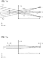
- Figures 1a, 1b are in different sectional planes only the relevant beam paths of partial beams TS_A, TS_B in the area of the mixing grating MG and several detector elements D1, D2, D3 shown.
- the Figures 2a - 2d serve to further explain the mixing grid MG.
- the measuring direction acts in the Figures 1a, 1b and 2a - 2d in each case the direction denoted by z.
- the moving objects can, for example, be machine parts, the relative position of which is to be determined.
- a scanning unit of the position measuring device can be connected to one of the two objects.
- the scanning unit here comprises various components such as a light source, several detector elements and one or more grids with different functions.
- a measuring reflector or a material measure of the position measuring device is connected to the other object.
- the position-dependent and phase-shifted incremental signals generated with the aid of the position measuring device according to the invention can be further processed, for example, by a machine control system in order to control the positioning of the corresponding machine parts.
- the diffraction order of the partial beam TS_A and the 1st diffraction order of the partial beam TS_B each emerge vertically from the mixing grating MG and then continue to propagate superimposed on one another in the direction of the centrally arranged detector element D2.
- the 0th order of diffraction of the partial beam TS_A and the +2 propagate.
- Diffraction order of the partial beam TS_B superimposed on one another to form the detector element D1; the 0th order of diffraction of the partial beam TS_B and the -2.
- Diffraction order of the partial beam TS_A propagate superimposed on one another to the detector element D3.
- the mixing grating MG consequently supplies at least a 0th order of diffraction and +/- 1st and +/- 2nd orders of diffraction of the partial beams TS_A, TS_B incident thereon in transmission.
- FIG Figure 2a A corresponding linear grating G M , designed as a four-stage transmission phase grating, which has the grating period d M , is shown in FIG Figure 2a shown in a schematic plan view.
- FIG. 2b A corresponding, rotationally symmetrical grating G L with the required focusing properties is shown in Figure 2b shown in a schematic plan view.
- the grating G L is also designed as a four-stage transmission phase grating. That is to say, four grating areas arranged one after the other are provided for each grating period in the radial direction, in which the partial beam bundles passing through each experience a different phase offset.
- the four phase different grating areas are also in Figure 2b shown differently according to the associated legend.
- FIG Figure 2c An exemplary embodiment of a mixing grating MG which is formed on the basis of the above considerations and at the same time has the required phase-shifting effects of the combining element and the focusing effect of the focusing element is shown in FIG Figure 2c shown schematically in a plan view.
- the mixing grating MG shown is designed as a multi-stage - specifically: four-stage - transmission phase grating, the four differently shown grating areas in the figure having different phase-shifting effects on the partial beams passing through.
- FIG. 2d a sectional view through the mixing grid from FIG. 3c along the indicated x-direction is shown.
- the four phase stages provided and the phase profile of the mixing grating MG provided along the x direction are clearly evident here.
- the first grid areas with a step height h there are further grid areas which each have step heights 2h, 3h and 4h.
- the mixing grid as a stepless grid or as a sawtooth grid.
- FIG Figure 3 A first specific exemplary embodiment of an optical position measuring device according to the invention, in which a diffractive mixing grating with the optical functionalities explained above is used, is shown in FIG Figure 3 shown in a schematic sectional side view.
- This position measuring device is used to detect the distance between two objects, not shown, which are connected to the measuring reflector 110 and the scanning unit 120 and which are arranged to be displaceable relative to one another along the vertical measuring direction z.
- the measuring reflector 110 consists of a carrier substrate 112 on which a plane mirror 114 is arranged. As can be seen from the figure, the reflecting side of the plane mirror 114 is oriented in the direction of the scanning unit 120.
- a light source 121 On the side of the scanning unit 120, a light source 121, a detector arrangement 125 with a plurality of optoelectronic detector elements and a transparent carrier body 137, for example made of glass, are provided; alternatively, a suitable hollow body could also be used as the carrier body.
- a suitable hollow body could also be used as the carrier body.
- FIG Figure 3 a truncated pyramidal cross-section.
- the support body 137 optically-functionally relevant elements arranged. These elements include a splitting element 132 arranged on the surface of the carrier body 137 facing the measuring reflector 110 and a mixing grid 135 as well as four deflecting elements 133a, 133b, 134a, 134b arranged on the carrier body side surfaces.
- a first deflecting element 133a and a second deflecting element 133b are arranged on the left side surface of the carrier body 137, and a third deflecting element 134a and a fourth deflecting element 134b are arranged on the right side surface of the carrier body 137.
- the splitting element 132 like the mixing grating 135, is designed as a transmission grating; in this exemplary embodiment, reflection grids with appropriately selected grating periods, whose reflective surfaces are oriented towards the interior of the carrier body 137, function as deflecting elements 133a, 133b, 134a, 134b.
- the bundle of rays emitted by the light source 121 first passes through an optically ineffective region 131 on that side of the carrier body 137 which faces the light source 121. After passing through the carrier body 137, the bundle of rays reaches the splitting element 132 and is split into two partial bundles of rays Figure 3 can be seen in the yz plane in the direction of the measuring reflector 110 and act on it a first time at the first impact locations.
- the partial beams are reflected back in the direction of the scanning unit 120, specifically in the direction of the first and second deflecting elements 133a, 133b.
- the partial beams of rays are then deflected by these deflecting elements 133a, 133b in the direction of the third and fourth deflecting elements 134a, 134b.
- the third and fourth deflecting elements 134a, 134b are then used to redirect the partial beams in the direction of the plane mirror 114 of the measuring reflector 110, which the partial beams then impinge on a second time at second points of incidence.
- the second impact locations on the plane mirror 114 can be compared to the first The points of incidence of the partial beams must be offset in the specified x-direction. From the second incidence locations 114, the partial beams are finally reflected back onto the mixing grating 135, which is designed as explained above and has the mentioned optical functionalities.
- the mixing grid 135 From the mixing grid 135, three pairs of superimposed, interfering partial beams then propagate through the carrier body 137, leave it through the optically ineffective area 136 and, due to the optical effect of the mixing grid 135, reach the three intended detector elements of the detector arrangement 125 in a focused manner optical functionalities of the mixing grating 135 with regard to phase-shifting and focusing effect, the mixing grating 135 in the present case also has a deflecting effect perpendicular to the plane of the drawing, ie the three pairs of partial beams propagate inclined with respect to the xz plane in the direction of the detector elements 125 125, a plurality of phase-shifted, position-dependent incremental signals with regard to the relative offset of measuring reflector 110 and scanning unit 120 along the measuring direction z can be detected.
- FIG. 4a and 4b A second embodiment of the position measuring device according to the invention is shown in two different sectional views in Figures 4a and 4b shown in schematic form.
- This exemplary embodiment of a position measuring device according to the invention serves to detect the relative movement of a material measure 210 and a scanning unit 220 along the measuring direction x; As can be seen from the figures, the measuring direction x is oriented vertically in this example. Two objects, which are movably arranged at least along the measuring direction x and are not shown in the figures, are in turn connected to the material measure 210 and the scanning unit 220.
- the material measure 210 consists of a reflection phase grating 214 which extends along the measuring direction x and which is arranged on a carrier substrate 212.
- the reflection phase grating 214 here comprises periodically arranged along the measuring direction x, Rectangular graduation areas with different phase-shifting effects on the incident beams.
- a light source 221, a plurality of optoelectronic detector elements 225 and a transparent scanning plate 237 with a plurality of optically function-relevant elements arranged thereon are provided. These include a plurality of scanning grids 233 arranged on the underside of scanning plate 237 and a mixing grating 235 arranged on the upper side.
- the underside here denotes that side of scanning plate 237 which faces measuring standard 10; the top of the scanning plate 237 is accordingly oriented away from the measuring standard 210.
- the scanning grating 233 and the mixing grating 235 are each designed as a transmission phase grating.
- the beam emitted by the light source 221 passes through the scanning plate 237 without further deflection or splitting and arrives at the top of the measuring standard 210, where the reflection phase grating is arranged. There, the incident beam is split into reflected partial beams of +/- 1st diffraction order, which then propagate back in the direction of the scanning unit 210 or the scanning plate 237.
- the angle of diffraction of the reflected partial beams to the measuring standard normal is identical in terms of amount to the angle of incidence to the measuring normal; the measuring standard 210 is thus illuminated in this variant at the so-called Littrow angle.
- the reflected partial beams then hit the scanning grids 233 on the underside of the scanning plate 237.
- the mixing grating 235 on the one hand, certain diffraction orders are superimposed in pairs, which are then in the direction of the further propagate downstream detector elements 225.
- the mixing grating 235 also takes over the focusing of the pairs of partial beams onto the individual detector elements 225.
- the correspondingly designed mixing grid 235 despite the large beam diameter on the measuring standard 210, an only small spot diameter on the detector elements 225 can be ensured.
- the large beam diameter on the material measure 210 ensured good insensitivity of the scanning to contamination that may occur on the material measure 210.
- the use of small detector elements is possible, which ensures only a low level of signal noise in the incremental signals generated.
- This exemplary embodiment of a position measuring device also serves, like the previous exemplary embodiment, to detect the relative movement of two movable objects along a vertical measuring direction, which in the Figures 5a, 5b is again denoted by x.
- the material measure 310 is formed here, which in turn consists of a reflection phase grating 314 which extends along the measuring direction x and which is arranged on a carrier substrate 312.
- a light source 321, several detector elements 325 and a transparent scanning plate 337 with several optically function-relevant elements arranged thereon are provided.
- several grids arranged on the underside of the scanning plate 237 namely a splitting grating 331, several scanning grids 333.1-333.4 and a mixing grating 335; these gratings are each designed as a transmission phase grating.
- two reflector elements 336, 338 are arranged, the reflective side of which is oriented in the direction of the measuring standard 310.
- the beam emitted by the light source 321 first passes through the scanning plate 337 until it reaches the splitting grating 331 arranged on the underside. There results a splitting into two partial beams, which then propagate further in the direction of the measuring standard 310. A back reflection takes place from the reflection phase grating 314 of the material measure 310 in the direction of the scanning unit 310. There the partial beams then pass through the scanning grids 333.2, 333.4, via which a deflection in the -y direction and a focusing on the reflector elements 336, 338 on the scanning plate Top results. The partial beam bundles are then reflected back to further scanning gratings 333.1, 333.3 on the underside of the scanning plate 337 by the reflector elements 336, 338.
- the partial beams are then collimated and deflected again via these scanning grids 333.1, 333.2, so that they finally impinge on the material measure 310 perpendicularly one more time in the xz plane.
- the partial beams then reached the mixing grating 335 on the underside of the scanning plate 337, which then exerts the optical effects already explained above on the partial beams. Pairs of interfering partial beams then propagate in a focused manner on the downstream detector elements 325 via which the phase-shifted incremental signals are generated.
- scanning beam paths can also be provided in the position measuring device according to the invention, in which those to be superimposed Partial beams do not fall on the mixing grating at symmetrical angles of incidence, as was initially shown in FIG Figures 1a, 1b was intended.
- a mixed grating can also be formed for such variants in the manner explained, which, in addition to setting defined phase relationships for the various partial beams, also ensures focusing on the detector elements.
- the position measuring device according to the invention is used not only for detecting displacement movements along linear measuring directions; Position measuring devices can also be designed that detect relative rotational movements of two objects, etc.
Description
Die vorliegende Erfindung betrifft eine optische Positionsmesseinrichtung, die zur hochgenauen Bestimmung der Relativposition zweier zueinander beweglicher Objekte geeignet ist.The present invention relates to an optical position measuring device which is suitable for the highly precise determination of the relative position of two objects that are movable relative to one another.
Aus dem Stand der Technik sind optische Positionsmesseinrichtungen bekannt, die als sogenannte 3-Gitter-Messsysteme ausgebildet sind. Diese dienen zur interferentiellen Bestimmung des Relativabstands von zwei Objekten, die entlang mindestens einer Messrichtung zueinander beweglich sind. Hierbei durchlaufen Teilstrahlenbündel, die aus einem von einer Lichtquelle emittierten Strahlenbündel aufgespalten werden, getrennte Strahlwege und beaufschlagen ein oder mehrere Gitter. Die Teilstrahlenbündel erfahren dabei abstandsabhängige Phasenverschiebungen, bevor sie auf einem Vereinigungselement zur interferierenden Überlagerung gelangen. Nach der Wieder-Überlagerung propagieren dann mindestens drei Paare interferierender Teilstrahlenbündel in verschiedene Raumrichtungen weiter und werden mit Hilfe eines Fokussierelements auf je ein Detektorelement fokussiert, so dass über die Detektorelemente mindestens drei positionsabhängige, phasenverschobene Inkrementalsignale erfassbar sind.Optical position measuring devices are known from the prior art, which are designed as so-called 3-grid measuring systems. These are used for the interferential determination of the relative distance between two objects that are movable to one another along at least one measuring direction. Partial beams, which are split up from a beam emitted by a light source, pass through separate beam paths and act on one or more grids. The partial bundles of rays experience distance-dependent phase shifts before they come to an interfering superposition on a combining element. After the re-overlay Then at least three pairs of interfering partial beams propagate in different spatial directions and are focused on one detector element each with the help of a focusing element, so that at least three position-dependent, phase-shifted incremental signals can be detected via the detector elements.
Als Vereinigungselement fungiert in derartigen Positionsmesseinrichtungen üblicherweise das letzte durchlaufene Gitter im Abtaststrahlengang. Dieses Gitter ist zumeist als lineares Transmissions-Phasengitter mit einer konstanten Ortsfrequenz ausgebildet. Über das Vereinigungselement werden die gewünschten Phasenverschiebungen bzw. -beziehungen zwischen den paarweise interferierenden Beugungsordnungen eingestellt, wozu in der Regel die Gitterparameter Stegbreite und Phasenhub des Transmissions-Phasengitters geeignet gewählt werden; diesbezüglich sei z.B. auf die
Üblicherweise besitzen in der Praxis die in Richtung der Detektorelemente propagierenden Paare von Teilstrahlenbündeln Durchmesser von mehreren Millimetern. In Verbindung mit der gewählten Gitterkonstante des Vereinigungselements führt dies in vielen Fällen zu einem Abstand zwischen dem Vereinigungselement und den Detektorelementen, der eine Überschreitung der zulässigen Baugröße der entsprechenden Positionsmesseinrichtung zur Folge hätte. Weiterhin ist zu beachten, dass die lichtempfindliche Fläche der einzelnen Detektorelemente jeweils eine bestimmte Mindestgröße aufweisen muss. Dies erweist sich aber als ungünstig im Hinblick auf resultierende Kapazitäten in den Detektorelementen und damit hinsichtlich der Grenzfrequenz der Positionsmesseinrichtung. Um einerseits die Baugröße der Positionsmesseinrichtung kompakt zu halten und andererseits die lichtempfindliche Fläche der Detektorelemente möglichst klein ausführen zu können, ist in derartigen Positionsmesseinrichtung daher dem Vereinigungselement oftmals ein Fokussierelement nachgeordnet, in dessen bildseitiger Brennebene die Detektorelemente angeordnet sind. Üblicherweise ist das Fokussierelement dabei als refraktive Linse ausgebildet, die einen gewissen Platzbedarf erfordert; auch diesbezüglich sei auf die bereits erwähnte
Die beschriebenen Positionsmesseinrichtungen können hierbei sowohl zur Erfassung von lateralen Relativbewegungen in Form einer relativen Linearverschiebung oder Rotation zweier zueinander beweglicher Objekte eingesetzt werden, wie dies z.B. in der
In beiden Anwendungen erweist sich jeweils als nachteilig, wenn in der entsprechenden Positionsmesseinrichtung das erforderliche Fokussierelement ein zu großes Bauvolumen benötigt und/oder insgesamt zu viele einzelne Komponenten bei der Montage zueinander justiert werden müssen.In both applications it turns out to be disadvantageous if the required focusing element in the corresponding position measuring device requires too large a structural volume and / or altogether too many individual components have to be adjusted to one another during assembly.
Aus der
Die Druckschrift
Der vorliegenden Erfindung liegt die Aufgabe zugrunde, eine optische Positionsmesseinrichtung der eingangs beschriebenen Art anzugeben, die kompakt bauend ausgebildet ist und einen möglichst geringen Aufwand bei der Justage der verschiedenen Komponenten erfordert.The present invention is based on the object of specifying an optical position measuring device of the type described at the outset, which is designed to be compact and requires as little effort as possible when adjusting the various components.
Diese Aufgabe wird erfindungsgemäß durch eine optische Positionsmesseinrichtung mit den Merkmalen des Anspruchs 1 gelöst.According to the invention, this object is achieved by an optical position measuring device having the features of
Vorteilhafte Ausführungen der erfindungsgemäßen optischen Positionsmesseinrichtung ergeben sich aus den Maßnahmen, die in den abhängigen Ansprüchen aufgeführt sind.Advantageous embodiments of the optical position measuring device according to the invention result from the measures that are listed in the dependent claims.
Die erfindungsgemäße optische Positionsmesseinrichtung dient zur interferentiellen Bestimmung des Relativabstands von zwei Objekten, die entlang mindestens einer Messrichtung zueinander beweglich sind. Hierbei wird ein von einer Lichtquelle emittiertes Strahlenbündel in mindestens zwei Teilstrahlenbündel aufgespalten, die anschließend auf getrennten Strahlwegen ein oder mehrere Gitter beaufschlagen und dabei abstandsabhängige Phasenverschiebungen erfahren. Die Teilstrahlenbündel werden an einem Mischgitter überlagert, dann propagieren mindestens drei Paare interferierender Teilstrahlenbündel in verschiedene Raumrichtungen, wobei über das Mischgitter ferner eine Fokussierung jedes Paares mit interferierenden Teilstrahlenbündeln auf ein Detektorelement erfolgt, so dass über die Detektorelemente mindestens drei positionsabhängige, phasenverschobene Inkrementalsignale erfassbar sind. Das Mischgitter ist dabei als n-stufiges Transmissions-Phasengitter ausgebildet, für dessen Stufenhöhe (h) gilt: ![]()
- h := Stufenhöhe
- λ := Lichtwellenlänge
- n := 2, 3, 4, .....
- n1 := Brechungsindex der Gitterstege
- n2 := Brechungsindex der Gitterlücken
- h: = step height
- λ: = light wavelength
- n: = 2, 3, 4, .....
- n1: = refractive index of the grating bars
- n2: = refractive index of the lattice gaps
Dabei kann vorgesehen sein, dass zwei auf das Mischgitter einfallende Teilstrahlenbündel mindestens eine Beugung in 0., +/- 1. und +/- 2. Beugungsordnung erfahren und in Richtung der Detektorelemente paarweise interferierende Teilstrahlenbündel 0./-2. Beugungsordnung, +1./-1. Beugungsordnung und 0./+2 Beugungsordnung propagieren.It can be provided that two partial beams incident on the mixing grating experience at least one diffraction in the 0th, +/- 1st and +/- 2nd order of diffraction and partial beams interfering in
Dabei kann das Mischgitter als n-stufiges Transmissions-Phasengitter ausgebildet sein, welches eine Phasenfunktion ϕ (x, y) gemäß ![]()
- ϕ (x, y) := Phasenfunktion des Transmissions-Phasengitters
- x, y := Ortskoordinaten in der Ebene des Transmissions-Phasengitters
- n := 2, 3, 4,...; Anzahl der Stufen des Transmissions-Phasengitters
- T (x, y) := Transmissionsfunktion des Mischgitters
- ϕ (x, y): = phase function of the transmission phase grating
- x, y: = location coordinates in the plane of the transmission phase grating
- n: = 2, 3, 4, ...; Number of stages of the transmission phase grating
- T (x, y): = transmission function of the mixing grating
In einer möglichen Ausführungsform ist vorgesehen, dass
- eines der beiden Objekte mit einem planen Messreflektor verbunden ist,
- das andere Objekt mit einer Abtasteinheit verbunden und entlang einer Messrichtung (z) relativ beweglich zum Messreflektor angeordnet ist, wobei die Messrichtung (z) senkrecht zum Messreflektor orientiert ist und
- wobei die Abtasteinheit folgende Komponenten aufweist:
- mindestens eine Lichtquelle,
- mehrere Detektorelemente,
- das Mischgitter,
- mehrere Umlenkelemente, die jeweils als eindimensionales Reflexionsgitter ausgebildet sind sowie
- mindestens ein Aufspaltelement, welches als eindimensionales Transmissionsgitter ausgebildet ist.
- one of the two objects is connected to a flat measuring reflector,
- the other object is connected to a scanning unit and is arranged to be movable along a measuring direction (z) relative to the measuring reflector, the measuring direction (z) being oriented perpendicular to the measuring reflector and
- wherein the scanning unit has the following components:
- at least one light source,
- several detector elements,
- the mixing grid,
- several deflection elements, each designed as a one-dimensional reflection grating, and
- at least one splitting element, which is designed as a one-dimensional transmission grating.
Dabei ist es möglich, dass die Abtasteinheit einen transparenten Trägerkörper mit pyramidenstumpfförmigem Querschnitt aufweist, an dessen dem Messreflektor zugewandten Fläche das Aufspaltelement angeordnet ist und an dessen Seitenflächen die mindestens vier Umlenkelemente angeordnet sind.It is possible that the scanning unit has a transparent support body with a truncated pyramid-shaped cross section, on whose surface facing the measuring reflector the splitting element is arranged and on whose side surfaces the at least four deflecting elements are arranged.
Mit Vorteil sind ferner die verschiedenen Komponenten in dieser Ausführungsform derart ausgebildet und angeordnet, dass
- das von der Lichtquelle emittierte Strahlenbündel am Aufspaltelement eine Aufspaltung in zwei Teilstrahlenbündel erfährt und die beiden Teilstrahlenbündel in Richtung des Messreflektors propagieren,
- vom Messreflektor eine Rückreflexion der Teilstrahlenbündel in Richtung der ersten und zweiten Umlenkelemente in der Abtasteinheit erfolgt, wo eine Umlenkung der Teilstrahlenbündel in Richtung der dritten und vierten Umlenkelemente resultiert und
- über die dritten und vierten Umlenkelemente eine Umlenkung der Teilstrahlenbündel zum Messreflektor erfolgt,
- von dem aus eine Rückreflexion der Teilstrahlenbündel in Richtung des Mischgitters in der Abtasteinheit resultiert, an dem eine Überlagerung der Teilstrahlenbündel erfolgt und dann drei Paare interferierender Teilstrahlenbündel in verschiedenen Raumrichtungen auf drei Detektorelemente fokussiert werden.
- the beam emitted by the light source is split into two partial beams at the splitting element and the two partial beams propagate in the direction of the measuring reflector,
- from the measuring reflector the partial beams are reflected back in the direction of the first and second deflecting elements in the scanning unit, where the partial beams are deflected in the direction of the third and fourth deflecting elements and
- The partial beams are deflected to the measuring reflector via the third and fourth deflection elements,
- from which a back reflection of the partial beams results in the direction of the mixing grating in the scanning unit, on which the partial beams are superimposed and then three pairs of interfering partial beams are focused in different spatial directions on three detector elements.
In einer weiteren Ausführungsform kann vorgesehen sein, dass
- eines der beiden Objekte mit einer Maßverkörperung verbunden ist,
- das andere Objekt mit einer Abtasteinheit verbunden und entlang einer Messrichtung (x) relativ beweglich zur Maßverkörperung angeordnet ist, wobei die Messrichtung (x) parallel zur Maßverkörperungsebene orientiert ist und
- wobei die Abtasteinheit folgende Komponenten aufweist:
- mindestens eine Lichtquelle,
- mehrere Detektorelemente,
- das Mischgitter,
- mehrere Abtastgitter, die jeweils als eindimensionales Transmissionsgitter ausgebildet sind.
- one of the two objects is connected to a measuring standard,
- the other object is connected to a scanning unit and is arranged so as to be movable along a measuring direction (x) relative to the measuring standard, the measuring direction (x) being oriented parallel to the measuring standard plane and
- wherein the scanning unit has the following components:
- at least one light source,
- several detector elements,
- the mixing grid,
- several scanning grids, each designed as a one-dimensional transmission grating.
Dabei ist es möglich, dass die Abtasteinheit ferner eine transparente Abtastplatte aufweist, auf deren Ober- und/oder Unterseite das Mischgitter und/oder die Abtastgitter angeordnet sind.It is possible that the scanning unit furthermore has a transparent scanning plate, on the upper and / or lower side of which the mixed grating and / or the scanning grids are arranged.
Ferner können dabei auf der Oberseite der Abtastplatte ein oder mehrere Reflektorelemente angeordnet sein, deren reflektierende Seite jeweils in Richtung der Maßverkörperung orientiert ist und auf der Unterseite das Mischgitter sowie die Abtastgitter angeordnet sind.Furthermore, one or more reflector elements can be arranged on the top of the scanning plate, the reflective side of which in each case in Direction of the material measure is oriented and the mixing grating and the scanning grating are arranged on the underside.
Maßgeblich für die vorliegende Erfindung ist demnach, ein Mischgitter im Abtaststrahlengang vorzusehen, welche die phasenschiebenden Eigenschaften des Vereinigungselements mit den abbildenden Eigenschaften des Fokussierelements kombiniert. Im Unterschied zum Stand der Technik mit den zwei erforderlichen Komponenten Vereinigungselement und Fokussierelement ist nunmehr mit dem Mischgitter nur noch ein einziges Bauelement in Form eines diffraktiven Bauteils in der erfindungsgemäßen Positionsmesseinrichtung vorgesehen. Auf diese Art und Weise kann eine Verringerung der Baugröße der entsprechenden Positionsmesseinrichtung und eine Minimierung der Anzahl an Komponenten ebenso sichergestellt werden wie eine vereinfachte Justage der erforderlichen optischen Bauteile. Die geringere Anzahl von Komponenten ermöglicht damit neben einer Kostenreduzierung auch eine Verringerung der Masse der entsprechenden Positionsmesseinrichtung.It is therefore essential for the present invention to provide a mixing grating in the scanning beam path which combines the phase-shifting properties of the combining element with the imaging properties of the focusing element. In contrast to the prior art with the two required components, the combining element and the focusing element, only a single component in the form of a diffractive component is now provided in the position measuring device according to the invention with the mixing grating. In this way, a reduction in the size of the corresponding position measuring device and a minimization of the number of components can be ensured, as can a simplified adjustment of the required optical components. The smaller number of components thus enables not only a cost reduction but also a reduction in the mass of the corresponding position measuring device.
Das erfindungsgemäß verwendete Mischgitter gestattet ferner die optimierte Anpassung der erforderlichen optischen Eigenschaften an die jeweilige Abtastung; so kann darüber etwa die gewünschte Fokusposition in der Detektionsebene über die Wahl einer geeigneten Brennweite des Mischgitters passend eingestellt werden.The mixing grating used according to the invention also allows the optimized adaptation of the required optical properties to the respective scanning; in this way, for example, the desired focus position in the detection plane can be set appropriately by selecting a suitable focal length of the mixing grid.
Es ist möglich, die erfindungsgemäße Positionsmesseinrichtung zur Erfassung von lateralen Relativbewegungen zweier beweglicher Objekte einzusetzen, die z.B. relativ zueinander verschiebbar oder verdrehbar angeordnet sind. Desweiteren kann mit Hilfe der erfindungsgemäßen Positionsmesseinrichtung aber auch die Erfassung von Relativbewegungen zweier Objekte entlang einer vertikalen Richtung vorgesehen sein.It is possible to use the position measuring device according to the invention for the detection of lateral relative movements of two movable objects which e.g. are arranged to be displaceable or rotatable relative to one another. Furthermore, however, the position measuring device according to the invention can also be used to detect relative movements of two objects along a vertical direction.
Weitere Einzelheiten und Vorteile der vorliegenden Erfindung seien anhand der nachfolgenden Beschreibung von Ausführungsbeispielen der erfindungsgemäßen Vorrichtung in Verbindung mit den Figuren erläutert.Further details and advantages of the present invention are explained with reference to the following description of exemplary embodiments of the device according to the invention in conjunction with the figures.
Es zeigt
- Figur 1a
- eine schematische Darstellung von Strahlengängen im Bereich des Mischgitters und der Detektorelemente einer erfindungsgemäßen Positionsmesseinrichtung in der xz-Ebene;
- Figur 1b
- eine weitere schematische Darstellung der Strahlengänge im Bereich des Mischgitters und der Detektorelemente einer erfindungsgemäßen Positionsmesseinrichtung in der yz-Ebene;
- Figur 2a
- eine schematisierte Draufsicht auf ein mehrstufiges, lineares Transmissions-Phasengitter zur Einstellung definierter Phasenverschiebungen zwischen paarweise interferierenden Beugungsordnungen;
- Figur 2b
- eine schematisierte Draufsicht auf ein mehrstufiges, rotationssymmetrisches Transmissions-Phasengitter mit fokussierender Wirkung;
- Figur 2c
- eine schematisierte Draufsicht auf ein geeignetes Mischgitter für eine erfindungsgemäße Positionsmesseinrichtung, ausgebildet als mehrstufiges Transmissions-Phasengitter, resultierend aus der Überlagerung der Transmissions-Phasengitter aus den
Figuren 2a und 2b ; - Figur 2d
- eine Schnittdarstellung des Mischgitters aus
Figur 2c entlang der x-Richtung zur Veranschaulichung des Phasenverlaufs; - Figur 3
- eine schematisierte Darstellung eines ersten Ausführungsbeispiels der erfindungsgemäßen Positionsmesseinrichtung, ausgebildet zur Erfassung einer vertikalen Relativbewegung, in einer Seitenansicht;
- Figur 4a, 4b
- jeweils eine schematisierte Darstellung eines zweiten Ausführungsbeispiels der erfindungsgemäßen Positionsmesseinrichtung in unterschiedlichen Schnittebenen, ausgebildet zur Erfassung einer lateralen Relativbewegung;
- Figur 5a, 5b
- jeweils eine schematisierte Darstellung eines dritten Ausführungsbeispiels der erfindungsgemäßen Positionsmesseinrichtung in unterschiedlichen Schnittebenen, ausgebildet zur Erfassung einer lateralen Relativbewegung.
- Figure 1a
- a schematic representation of beam paths in the area of the mixing grating and the detector elements of a position measuring device according to the invention in the xz plane;
- Figure 1b
- a further schematic representation of the beam paths in the area of the mixing grating and the detector elements of a position measuring device according to the invention in the yz plane;
- Figure 2a
- a schematic plan view of a multi-level, linear transmission phase grating for setting defined phase shifts between pairs of interfering diffraction orders;
- Figure 2b
- a schematic plan view of a multi-stage, rotationally symmetrical transmission phase grating with a focusing effect;
- Figure 2c
- a schematic top view of a suitable mixing grating for a position measuring device according to the invention, designed as a multi-stage transmission phase grating, resulting from the superposition of the transmission phase grating from the
Figures 2a and 2b ; - Figure 2d
- a sectional view of the mixing grid
Figure 2c along the x-direction to illustrate the phase profile; - Figure 3
- a schematic representation of a first embodiment of the position measuring device according to the invention, designed to detect a vertical relative movement, in a side view;
- Figure 4a, 4b
- each a schematic representation of a second exemplary embodiment of the position measuring device according to the invention in different sectional planes, designed to detect a lateral relative movement;
- Figure 5a, 5b
- each a schematic representation of a third exemplary embodiment of the position measuring device according to the invention in different sectional planes, designed to detect a lateral relative movement.
Bevor anhand der
Als Messrichtung fungiert in den
Entscheidend für die vorliegende Erfindung ist, bestimmte optische Funktionalitäten, die vormals in separaten Bauteilen der optischen Positionsmesseinrichtung implementiert wurden, nunmehr in einem einzigen Mischgitter MG zu kombinieren, das als diffraktives Bauteil ausgebildet ist. Das heißt, die phasenschiebenden Wirkungen eines Vereinigungselements und die fokussierende Wirkung eines Fokussierelements auf die Teilstrahlenbündel TS_A, TS_B werden gemäß der vorliegenden Erfindung im Mischgitter MG kombiniert. Wie nachfolgend noch im Detail erläutert wird, ist das in
Anhand der
Im Fall einer derartigen Überlagerung der verschiedenen Beugungsordnungen muss ein hierzu verwendetes Gitter GM dann eine Gitterperiode dM aufweisen, für die gilt: ![]()
- dM := Gitterperiode eines Gitters GM, welches 0. sowie +/- 1. und +/- 2. Beugungsordnungen liefert
- λ := Lichtwellenlänge
- α := Einfallswinkel der Teilstrahlenbündel, die auf das Gitter GM einfallen
- d M : = grating period of a grating G M , which supplies 0th as well as +/- 1st and +/- 2nd diffraction orders
- λ: = light wavelength
- α: = angle of incidence of the partial beams that impinge on the grating G M
Eine entsprechendes lineares Gitter GM, ausgebildet als vierstufiges Transmissions-Phasengitter, das die Gitterperiode dM aufweist, ist in
Unter Berücksichtigung der gewünschten Phasenbeziehungen der resultierenden Inkrementalsignale, vorzugsweise in Form einer relativen Phasendifferenz von ca. 120° bei drei Inkrementalsignalen, ergibt sich für die komplexe Transmissionsfunktion TM (x) des Gitters GM dann die folgende Beziehung: ![]()
- TM (x) := komplexe Transmissionsfunktion des Gitters GM
- x := Ortskoordinate
- dM := Gitterkonstante des Gitters GM
- T M (x): = complex transmission function of the grating G M
- x: = location coordinate
- d M : = lattice constant of the lattice G M
Um die erforderliche Transmissionsfunktion T(x, y) des eigentlichen Mischgitters MG mit der gewünschten Fokussierungs-Funktionalität zu erhalten, muss die komplexe Transmissionsfunktion TM (x) des Gitters GM mit der Linsentransmissionsfunktion TL (x, y) eines geeignet fokussierenden, weiteren Gitters GL multipliziert werden. Die Linsentransmissionsfunktion TL (x, y) eines derartigen, fokussierenden Gitters GL ergibt sich hierbei gemäß nachfolgender Beziehung: ![]()
- TL (x, y) := Linsentransmissionsfunktion des fokussierenden Gitters GL
- x, y := Ortskoordinaten in der Fokusebene
- λ := Lichtwellenläge
- T L (x, y): = lens transmission function of the focusing grating G L
- x, y: = location coordinates in the focal plane
- λ: = light wave length
Ein entsprechendes, rotationssymmetrisches Gitter GL mit den erforderlichen Fokussierungseigenschaften ist in
Die erforderliche Transmissionsfunktion T (x, y) des Mischgitters MG, das die optischen Eigenschaften der beiden Gitter GM und GL vereint, resultiert dann gemäß ![]()
- T (x, y) := Transmissionsfunktion des Mischgitters MG
- TM (x) := komplexe Transmissionsfunktion des Gitters GM
- TL (x, y) := Linsentransmissionsfunktion des Gitters GL
- T (x, y): = transmission function of the mixing grating MG
- T M (x): = complex transmission function of the grating G M
- T L (x, y): = lens transmission function of the grating G L
Gemäß Gleichung 4 besitzt das Mischgitter MG eine Struktur, welche auf die einfallenden Teilstrahlenbündel eine amplituden- und phasenmodulierende Wirkung besitzt. Um den Herstellungsaufwand zu reduzieren, kann ein Mischgitter MG mit den erforderlichen optischen Eigenschaften in einer möglichen Ausführungsform durch ein n-stufiges Phasengitter mit einer Phasenfunktion ϕ(x,y) gemäß nachfolgender Gleichung (5) approximiert werden. ![]()
- ϕ(x, y) := Phasenfunktion des Mischgitters MG
- n := ganzzahlig; Anzahl der verschiedenen Phasengitter-Stufen
- T (x, y) := Transmissionsfunktion des Mischgitters MG
- ϕ (x, y): = phase function of the mixing grating MG
- n: = integer; Number of different phase grating levels
- T (x, y): = transmission function of the mixing grating MG
Ein Ausführungsbeispiel eines Mischgitters MG, das auf Grundlage der vorstehenden Überlegungen ausgebildet ist und gleichzeitig die geforderten phasenschiebenden Wirkungen des Vereinigungselements und die fokussierende Wirkung des Fokussierelements aufweist, ist in
In
Allgemein gilt im Fall eines n-stufigen Transmissions-Phasengitters für die Stufenhöhe h: ![]()
- h := Stufenhöhe
- λ := Lichtwellenlänge
- n := 2, 3, 4, .....
- n1 := Brechungsindex der Gitterstege
- n2 := Brechungsindex der Gitterlücken
- h: = step height
- λ: = light wavelength
- n: = 2, 3, 4, .....
- n1: = refractive index of the grating bars
- n2: = refractive index of the lattice gaps
Alternativ zur Ausbildung als Transmissions-Phasengitter wäre es grundsätzlich auch möglich, das Mischgitter als Reflexions-Phasengitter auszuführen. Besonders geeignet hierzu wären etwa hochreflektierende Materialien wie z.B. Gold oder Aluminium. In einem solchen Fall gilt dann für die Stufenhöhe h eines n-stufigen Reflexions-Phasengitters: ![]()
- h := Stufenhöhe
- λ := Lichtwellenlänge
- n = : 2, 3, 4, ....
- h: = step height
- λ: = light wavelength
- n =: 2, 3, 4, ....
Desweiteren wäre es auch grundsätzlich möglich, das Mischgitter als stufenloses Gitter oder als Sägezahngitter auszubilden.Furthermore, it would in principle also be possible to design the mixing grid as a stepless grid or as a sawtooth grid.
Ein erstes konkretes Ausführungsbeispiel einer erfindungsgemäßen optischen Positionsmesseinrichtung, in der ein diffraktives Mischgitter mit den oben erläuterten optischen Funktionalitäten verwendet wird, ist in
Der Messreflektor 110 besteht im gezeigten Ausführungsbeispiel aus einem Trägersubstrat 112, auf dem ein Planspiegel 114 angeordnet ist. Die reflektierende Seite des Planspiegels 114 ist wie aus der Figur ersichtlich in Richtung der Abtasteinheit 120 orientiert.In the exemplary embodiment shown, the measuring
Auf Seiten der Abtasteinheit 120 ist eine Lichtquelle 121, eine Detektoranordnung 125 mit mehreren optoelektronischen Detektorelementen sowie ein transparenter Trägerkörper 137, z.B. aus Glas, vorgesehen; alternativ wäre als Trägerkörper im Übrigen auch ein geeigneter Hohlkörper verwendbar. Der Trägerkörper 137 besitzt gemäß der Ansicht in
Nachfolgend sei der zur Signalerzeugung genutzte Strahlengang des ersten Ausführungsbeispiels der erfindungsgemäßen Positionsmesseinrichtung erläutert. Wie aus
Ein zweites Ausführungsbeispiel der erfindungsgemäßen Positionsmesseinrichtung ist in zwei verschiedenen Schnittansichten in den
Die Maßverkörperung 210 besteht im vorliegenden Beispiel aus einem sich entlang der Messrichtung x erstreckenden Reflexions-Phasengitter 214, das auf einem Trägersubstrat 212 angeordnet ist. Das Reflexions-Phasengitter 214 umfasst hierbei periodisch entlang der Messrichtung x angeordnete, rechteckförmige Teilungsbereiche mit unterschiedlichen phasenschiebenden Wirkungen auf die darauf einfallenden Strahlenbündel.In the present example, the
Auf Seiten der Abtasteinheit 220 ist eine Lichtquelle 221, mehrere optoelektronische Detektorelemente 225 sowie eine transparente Abtastplatte 237 mit mehreren darauf angeordneten, optisch funktions-relevanten Elementen vorgesehen. Hierzu gehören mehrere auf der Unterseite der Abtastplatte 237 angeordnete Abtastgitter 233 sowie ein auf der Oberseite angeordnetes Mischgitter 235. Als Unterseite wird hierbei diejenige Seite der Abtastplatte 237 bezeichnet, die der Maßverkörperung 10 zugewandt ist; die Oberseite der Abtastplatte 237 ist demzufolge abgewandt zur Maßverkörperung 210 orientiert. Die Abtastgitter 233 sowie das Mischgitter 235 sind jeweils als Transmissions-Phasengitter ausgebildet.On the side of the
Das von der Lichtquelle 221 emittierte Strahlenbündel durchtritt ohne weitere Ablenkung oder Aufspaltung die Abtastplatte 237 und gelangt auf die Oberseite der Maßverkörperung 210, wo das Reflexions-Phasengitter angeordnet ist. Dort resultiert eine Aufspaltung des einfallenden Strahlenbündels in reflektierte Teilstrahlenbündel +/- 1. Beugungsordnung, die dann wieder zurück in Richtung der Abtasteinheit 210 bzw. der Abtastplatte 237 propagieren. Wie aus der Schnittansicht in
Wie bereits oben angedeutet, kann aufgrund der Verwendung des entsprechend ausgebildeten Mischgitters 235 trotz großer Strahldurchmesser auf der Maßverkörperung 210 ein lediglich kleiner Spot-Durchmesser auf den Detektorelementen 225 gewährleistet werden. Der große Strahldurchmesser auf der Maßverkörperung 210 stellte eine gute Unempfindlichkeit der Abtastung gegenüber Verschmutzungen sicher, die evtl. auf der Maßverkörperung 210 auftreten können. Desweiteren ist die Verwendung kleiner Detektorelemente möglich, womit ein nur geringes Signalrauschen in den erzeugten Inkrementalsignalen sichergestellt ist.As already indicated above, due to the use of the correspondingly designed
Abschließend sei anhand der
Auch dieses Ausführungsbeispiel einer erfindungsgemäßen Positionsmesseinrichtung dient wie das vorhergehende Ausführungsbeispiel zur Erfassung der Relativbewegung zweier beweglicher Objekte entlang einer vertikalen Messrichtung, die in den
Analog zum zweiten Ausführungsbeispiel ist hierbei die Maßverkörperung 310 ausgebildet, die wiederum aus einem sich entlang der Messrichtung x erstreckenden Reflexions-Phasengitter 314 besteht, das auf einem Trägersubstrat 312 angeordnet ist.Analogous to the second exemplary embodiment, the
In der Abtasteinheit 320 ist eine Lichtquelle 321, mehrere Detektorelemente 325 sowie eine transparente Abtastplatte 337 mit mehreren darauf angeordneten, optisch funktions-relevanten Elementen vorgesehen. Hierzu gehören mehrere auf der Unterseite der Abtastplatte 237 angeordnete Gitter, nämlich ein Aufspaltgitter 331, mehrere Abtastgitter 333.1 - 333.4 und ein Mischgitter 335; diese Gitter sind jeweils als Transmissions-Phasengitter ausgebildet. Auf der Oberseite der Abtastplatte 237 sind zwei Reflektorelemente 336, 338, angeordnet, deren reflektierende Seite jeweils in Richtung der Maßverkörperung 310 orientiert ist.In the
Das von der Lichtquelle 321 emittierte Strahlenbündel durchläuft zunächst die Abtastplatte 337, bis es auf das auf der Unterseite angeordnete Aufspaltgitter 331 gelangt. Dort resultiert eine Aufspaltung in zwei Teilstrahlenbündel, die dann weiter in Richtung der Maßverkörperung 310 propagieren. Vom Reflexions-Phasengitter 314 der Maßverkörperung 310 erfolgt eine Rückreflexion in Richtung der Abtasteinheit 310. Dort durchlaufen die Teilstrahlenbündel dann die Abtastgitter 333.2, 333.4, über die eine Ablenkung in -y-Richtung sowie eine Fokussierung auf die Reflektorelemente 336, 338 auf der Abtastplatten-Oberseite resultiert. Von den Reflektorelementen 336, 338 werden die Teilstrahlenbündel dann zurück zu weiteren Abtastgittern 333.1, 333.3 auf der Unterseite der Abtastplatte 337 reflektiert. Über diese Abtastgitter 333.1, 333.2 werden die Teilstrahlenbündel dann kollimiert und erneut abgelenkt, so dass sie in der xz-Ebene schließlich senkrecht ein weiteres Mal auf die Maßverkörperung 310 einfallen. Nach der erneuten Rückreflexion gelang die Teilstrahlenbündel dann auf das Mischgitter 335 an der Unterseite der Abtastplatte 337 , das dann die bereits oben erläuterten optischen Wirkungen auf die Teilstrahlenbündel ausübt. Es propagieren sodann Paare von interferierenden Teilstrahlenbündeln fokussiert auf die nachgeordneten Detektorelemente 325, über die die phasenverschobenen Inkrementalsignale erzeugt werden.The beam emitted by the
Neben den konkret beschriebenen Ausführungsbeispielen existieren im Rahmen der vorliegenden Erfindung selbstverständlich noch weitere Ausgestaltungsmöglichkeiten.In addition to the specifically described exemplary embodiments, there are of course still further design options within the scope of the present invention.
So können z.B. auch Abtaststrahlengänge in der erfindungsgemäßen Positionsmesseinrichtung vorgesehen sein, bei denen die zu überlagernden Teilstrahlenbündel nicht unter symmetrischen Einfallswinkeln auf das Mischgitter einfallen, wie dies eingangs in den
Ferner ist es möglich, dass die erfindungsgemäße Positionsmesseinrichtung nicht nur zur Erfassung von Verschiebebewegungen entlang linearer Messrichtungen eingesetzt wird; es können auch Positionsmesseinrichtungen ausgebildet werden, die rotatorische Relativbewegungen zweier Objekte erfassen usw..Furthermore, it is possible that the position measuring device according to the invention is used not only for detecting displacement movements along linear measuring directions; Position measuring devices can also be designed that detect relative rotational movements of two objects, etc.
Claims (9)
- Optical position measuring device for determining, by interference, the relative distance between two objects that are movable relative to one another along at least one measurement direction, wherein a beam emitted by light source is split into at least two partial beams, which subsequently impinge on one or more gratings along separate beam paths and, in the process, experience distance-dependent phase shifts,
characterized- in that the partial beams (TS_A, TS_B) are overlaid at a mixing grating (MG; 135; 235; 335) and subsequently at least three pairs of interfering partial beams (TS_A, TS_B) propagate in different spatial directions, wherein the mixing grating (MG; 135; 235; 335) furthermore brings about focusing of each pair with interfering partial beams (TS_A, TS_B) on a detector element (D1, D2, D3; 125; 225; 325) such that at least three position-dependent, phase-shifted incremental signals are capturable by way of the detector elements (D1, D2, D3; 125; 225; 325) and- the mixing grating (MG; 135; 235; 335) is embodied as n-step transmission phase grating, the following applying to the step height (h) thereof:where: h := step heightλ := light wavelengthn := 2, 3, 4, ...n1 := refractive index of the grating websn2 := refractive index of the grating gaps.
 - Optical position measuring device according to Claim 1, characterized in that two partial beams (TS_A, TS_B) incident on the mixing grating (MG; 135; 235; 335) experience at least one diffraction into the 0th, +/-1st and +/-2nd order of diffraction and pairwise interfering partial beams of the 0th/-2nd order of diffraction, +1st/-1st order of diffraction and 0th/+2nd order of diffraction propagate in the direction of the detector elements (D1, D2, D3; 125; 225; 325).
- Optical position measuring device according to Claim 1, characterized in that the mixing grating (MG; 135; 235; 335) is embodied as a n-step transmission phase grating, which has a phase function ϕ(x, y) as per
 ϕ(x, y) := phase function of the transmission phase grating,x, y := spatial coordinates in the plane of the transmission phase grating,n := 2, 3, 4, ...; number of steps of the transmission phase grating, andT(x, y) := transmission function of the mixing grating.
 - Optical position measuring device according to at least one of the preceding claims, characterized in that- one of the two objects is connected to a plane measuring reflector (110),- the other object is connected to a scanning unit (120) and arranged so as to be movable relative to the measuring reflector (110) along one measuring direction (z), wherein the measuring direction (z) is oriented perpendicular to the measuring reflector (110), and- wherein the scanning unit (120) comprises the following components:- at least one light source (121),- a plurality of detector elements (125),- the mixing grating (135),- a plurality of deflection elements (133a, 133b, 134a, 134b), each of which are embodied as a one-dimensional reflection grating, and- at least one splitting element (132), which is embodied as a one-dimensional transmission grating.
- Apparatus according to Claim 4, characterized in that the scanning unit (120) has a transparent carrying body (137) with a pyramidal frustum-shaped cross section, the splitting element (132) being arranged on the face thereof facing the measuring reflector (110) and the at least four deflection elements (133a, 133b, 134a, 134b) being arranged at the side faces thereof.
- Apparatus according to Claim 4, characterized in that the various components are embodied and arranged in such way that- the beam emitted by the light source (121) experiences splitting into two partial beams at the splitting element (132) and the two partial beams propagate in the direction of the measuring reflector (110),- there is a back-reflection of the partial beam from the measuring reflector (110) in the direction of the first and second deflection elements (133a, 133b) of the scanning unit (120) where there is a deflection of the partial beams in the direction of the third and fourth deflection elements (134a, 134b), and- there is a deflection of the partial beams to the measuring reflector (110) via the third and fourth deflection elements (134a, 134b),- there is a back-reflection of the partial beams in the direction of the mixing grating (135) in the scanning unit (120) where there is a superposition of the partial beams and then three pairs interfering partial beams are focused on three detector elements (125) in different spatial directions.
- Optical position measuring device according to at least one of Claims 1 to 3, characterized in that- one of the two objects is connected to a material measure (210; 310),- the other object is connected to a scanning unit (220; 330) and arranged so as to be movable relative to the material measure (210; 310) along a measuring direction (x), when the measuring direction (x) is oriented parallel to the material measure plane, and- wherein the scanning unit (220; 320) comprises the following components:- at least one light source (221; 321),- a plurality of detector elements (225; 325),- the mixing grating (235; 335),- a plurality of scanning gratings (233; 333.1, 333.2, 333.3, 333.4), each of which are embodied as a one-dimensional transmission grating.
- Optical position measuring device according to Claim 7, characterized in that the scanning unit (220; 320) further has a transparent scanning plate (237; 337), on the upper and/or lower side of which the mixing grating (235; 335) and/or the scanning gratings (233; 333.1, 333.2, 333.3, 333.4) are arranged.
- Optical position measuring device according to Claim 8, characterised in that one or more reflector elements (336, 338) are arranged on the upper side of the scanning plate (337), the reflecting side of said reflector elements each being oriented in the direction of the material measure (310), and the mixing grating (335) and scanning gratings (333.1, 333.2, 333.3, 333.4) are arranged on the lower side.
Applications Claiming Priority (1)
| Application Number | Priority Date | Filing Date | Title |
|---|---|---|---|
| DE102018212719.0A DE102018212719A1 (en) | 2018-07-31 | 2018-07-31 | Optical position measuring device |
Publications (2)
| Publication Number | Publication Date |
|---|---|
| EP3605026A1 EP3605026A1 (en) | 2020-02-05 |
| EP3605026B1 true EP3605026B1 (en) | 2020-11-18 |
Family
ID=67402859
Family Applications (1)
| Application Number | Title | Priority Date | Filing Date |
|---|---|---|---|
| EP19186786.0A Active EP3605026B1 (en) | 2018-07-31 | 2019-07-17 | Optical positioning device |
Country Status (5)
| Country | Link |
|---|---|
| US (1) | US10823550B2 (en) |
| EP (1) | EP3605026B1 (en) |
| JP (1) | JP7201547B2 (en) |
| CN (1) | CN110779447B (en) |
| DE (1) | DE102018212719A1 (en) |
Families Citing this family (1)
| Publication number | Priority date | Publication date | Assignee | Title |
|---|---|---|---|---|
| JP2022083072A (en) * | 2020-11-24 | 2022-06-03 | 株式会社ミツトヨ | Displacement sensor and shape measurement apparatus |
Family Cites Families (12)
| Publication number | Priority date | Publication date | Assignee | Title |
|---|---|---|---|---|
| GB1400253A (en) * | 1972-03-17 | 1975-07-16 | Ti Group Services Ltd | Gauging dimensions |
| GB8413955D0 (en) | 1984-05-31 | 1984-07-04 | Pa Consulting Services | Displacement measuring apparatus |
| JPH09284684A (en) * | 1996-04-17 | 1997-10-31 | Hitachi Ltd | Single ccd type color liquid crystal display device |
| EP0978708B1 (en) * | 1998-08-01 | 2005-10-05 | Dr. Johannes Heidenhain GmbH | Rotary encoder |
| DE102006042743A1 (en) * | 2006-09-12 | 2008-03-27 | Dr. Johannes Heidenhain Gmbh | Position measuring device |
| DE102008007319A1 (en) * | 2008-02-02 | 2009-08-06 | Dr. Johannes Heidenhain Gmbh | Optical position measuring device |
| DE102011082156A1 (en) * | 2010-12-16 | 2012-06-21 | Dr. Johannes Heidenhain Gmbh | Optical position measuring device |
| DE102012222077A1 (en) * | 2012-12-03 | 2014-06-05 | Dr. Johannes Heidenhain Gmbh | Position measuring device |
| DE102013222383A1 (en) * | 2013-02-06 | 2014-08-07 | Dr. Johannes Heidenhain Gmbh | Optical position measuring device |
| DE102013206693A1 (en) * | 2013-04-15 | 2014-10-16 | Dr. Johannes Heidenhain Gmbh | Device for interferential distance measurement |
| JP6696748B2 (en) * | 2014-10-21 | 2020-05-20 | ドクトル・ヨハネス・ハイデンハイン・ゲゼルシヤフト・ミツト・ベシユレンクテル・ハフツングDr. Johannes Heidenhain Gesellschaft Mit Beschrankter Haftung | Optical encoder |
| CN104729411B (en) * | 2015-03-10 | 2017-07-14 | 中国科学院上海光学精密机械研究所 | High-resolution gration interferometer based on high dencity grating |
-
2018
- 2018-07-31 DE DE102018212719.0A patent/DE102018212719A1/en not_active Withdrawn
-
2019
- 2019-07-11 JP JP2019129096A patent/JP7201547B2/en active Active
- 2019-07-17 EP EP19186786.0A patent/EP3605026B1/en active Active
- 2019-07-25 US US16/522,037 patent/US10823550B2/en active Active
- 2019-07-31 CN CN201910699725.7A patent/CN110779447B/en active Active
Non-Patent Citations (1)
| Title |
|---|
| None * |
Also Published As
| Publication number | Publication date |
|---|---|
| DE102018212719A1 (en) | 2020-02-20 |
| US10823550B2 (en) | 2020-11-03 |
| CN110779447B (en) | 2023-08-22 |
| US20200041252A1 (en) | 2020-02-06 |
| JP2020020788A (en) | 2020-02-06 |
| CN110779447A (en) | 2020-02-11 |
| JP7201547B2 (en) | 2023-01-10 |
| EP3605026A1 (en) | 2020-02-05 |
Similar Documents
| Publication | Publication Date | Title |
|---|---|---|
| EP2149036B1 (en) | Optical position measuring device | |
| EP1739395B1 (en) | Position measuring device | |
| DE19748802B4 (en) | Optical position measuring device | |
| DE102013004869B4 (en) | Method for forming a structuring on surfaces of components with a laser beam | |
| EP1923672B1 (en) | Position measuring device | |
| EP2388558B1 (en) | Optical positioning device | |
| DE102008007319A1 (en) | Optical position measuring device | |
| EP2450673B1 (en) | Optical positioning device | |
| EP3258220B1 (en) | Optical positioning device | |
| DE102005036180B4 (en) | Optical position measuring device | |
| EP3059554B1 (en) | Optical positioning device | |
| EP2980525B1 (en) | Interferometer mit dreifachem durchgang | |
| EP3605026B1 (en) | Optical positioning device | |
| EP1992915B1 (en) | Position measuring device | |
| EP2869034B1 (en) | Position sensing device | |
| DE102011005937B4 (en) | Device for interferential distance measurement | |
| DE2852497C2 (en) | Scanner with a recording device working with a light beam | |
| DE102019108681A1 (en) | Device and method for generating a double or multiple spot in laser material processing | |
| EP3835727B1 (en) | Optical positioning device | |
| DE112014001977B4 (en) | Device for interferential distance measurement | |
| EP3936830B1 (en) | Optical positioning device | |
| EP1318524A2 (en) | X-ray optical system and method for imaging a source | |
| WO2021219278A1 (en) | Microscope arrangement and method for measuring a surface structure of a sample, and diffractive optical element | |
| WO2002029828A1 (en) | Method and device for influencing x-radiation |
Legal Events
| Date | Code | Title | Description |
|---|---|---|---|
| PUAI | Public reference made under article 153(3) epc to a published international application that has entered the european phase |
Free format text: ORIGINAL CODE: 0009012 |
|
| STAA | Information on the status of an ep patent application or granted ep patent |
Free format text: STATUS: REQUEST FOR EXAMINATION WAS MADE |
|
| STAA | Information on the status of an ep patent application or granted ep patent |
Free format text: STATUS: EXAMINATION IS IN PROGRESS |
|
| 17P | Request for examination filed |
Effective date: 20190717 |
|
| AK | Designated contracting states |
Kind code of ref document: A1 Designated state(s): AL AT BE BG CH CY CZ DE DK EE ES FI FR GB GR HR HU IE IS IT LI LT LU LV MC MK MT NL NO PL PT RO RS SE SI SK SM TR |
|
| AX | Request for extension of the european patent |
Extension state: BA ME |
|
| 17Q | First examination report despatched |
Effective date: 20200110 |
|
| GRAP | Despatch of communication of intention to grant a patent |
Free format text: ORIGINAL CODE: EPIDOSNIGR1 |
|
| STAA | Information on the status of an ep patent application or granted ep patent |
Free format text: STATUS: GRANT OF PATENT IS INTENDED |
|
| RIC1 | Information provided on ipc code assigned before grant |
Ipc: G01D 5/38 20060101AFI20200508BHEP |
|
| INTG | Intention to grant announced |
Effective date: 20200603 |
|
| RBV | Designated contracting states (corrected) |
Designated state(s): AL AT BE BG CH CY CZ DE DK EE ES FI FR GB GR HR HU IE IS IT LI LT LU LV MC MK MT NL NO PL PT RO RS SE SI SK SM TR |
|
| GRAS | Grant fee paid |
Free format text: ORIGINAL CODE: EPIDOSNIGR3 |
|
| GRAA | (expected) grant |
Free format text: ORIGINAL CODE: 0009210 |
|
| STAA | Information on the status of an ep patent application or granted ep patent |
Free format text: STATUS: THE PATENT HAS BEEN GRANTED |
|
| AK | Designated contracting states |
Kind code of ref document: B1 Designated state(s): AL AT BE BG CH CY CZ DE DK EE ES FI FR GB GR HR HU IE IS IT LI LT LU LV MC MK MT NL NO PL PT RO RS SE SI SK SM TR |
|
| REG | Reference to a national code |
Ref country code: GB Ref legal event code: FG4D Free format text: NOT ENGLISH |
|
| REG | Reference to a national code |
Ref country code: CH Ref legal event code: EP |
|
| REG | Reference to a national code |
Ref country code: IE Ref legal event code: FG4D Free format text: LANGUAGE OF EP DOCUMENT: GERMAN |
|
| REG | Reference to a national code |
Ref country code: DE Ref legal event code: R096 Ref document number: 502019000421 Country of ref document: DE |
|
| REG | Reference to a national code |
Ref country code: CH Ref legal event code: NV Representative=s name: ICB INGENIEURS CONSEILS EN BREVETS SA, CH Ref country code: AT Ref legal event code: REF Ref document number: 1336254 Country of ref document: AT Kind code of ref document: T Effective date: 20201215 |
|
| REG | Reference to a national code |
Ref country code: NL Ref legal event code: FP |
|
| PG25 | Lapsed in a contracting state [announced via postgrant information from national office to epo] |
Ref country code: PT Free format text: LAPSE BECAUSE OF FAILURE TO SUBMIT A TRANSLATION OF THE DESCRIPTION OR TO PAY THE FEE WITHIN THE PRESCRIBED TIME-LIMIT Effective date: 20210318 Ref country code: RS Free format text: LAPSE BECAUSE OF FAILURE TO SUBMIT A TRANSLATION OF THE DESCRIPTION OR TO PAY THE FEE WITHIN THE PRESCRIBED TIME-LIMIT Effective date: 20201118 Ref country code: FI Free format text: LAPSE BECAUSE OF FAILURE TO SUBMIT A TRANSLATION OF THE DESCRIPTION OR TO PAY THE FEE WITHIN THE PRESCRIBED TIME-LIMIT Effective date: 20201118 Ref country code: NO Free format text: LAPSE BECAUSE OF FAILURE TO SUBMIT A TRANSLATION OF THE DESCRIPTION OR TO PAY THE FEE WITHIN THE PRESCRIBED TIME-LIMIT Effective date: 20210218 Ref country code: GR Free format text: LAPSE BECAUSE OF FAILURE TO SUBMIT A TRANSLATION OF THE DESCRIPTION OR TO PAY THE FEE WITHIN THE PRESCRIBED TIME-LIMIT Effective date: 20210219 |
|
| PG25 | Lapsed in a contracting state [announced via postgrant information from national office to epo] |
Ref country code: SE Free format text: LAPSE BECAUSE OF FAILURE TO SUBMIT A TRANSLATION OF THE DESCRIPTION OR TO PAY THE FEE WITHIN THE PRESCRIBED TIME-LIMIT Effective date: 20201118 Ref country code: PL Free format text: LAPSE BECAUSE OF FAILURE TO SUBMIT A TRANSLATION OF THE DESCRIPTION OR TO PAY THE FEE WITHIN THE PRESCRIBED TIME-LIMIT Effective date: 20201118 Ref country code: LV Free format text: LAPSE BECAUSE OF FAILURE TO SUBMIT A TRANSLATION OF THE DESCRIPTION OR TO PAY THE FEE WITHIN THE PRESCRIBED TIME-LIMIT Effective date: 20201118 Ref country code: IS Free format text: LAPSE BECAUSE OF FAILURE TO SUBMIT A TRANSLATION OF THE DESCRIPTION OR TO PAY THE FEE WITHIN THE PRESCRIBED TIME-LIMIT Effective date: 20210318 Ref country code: BG Free format text: LAPSE BECAUSE OF FAILURE TO SUBMIT A TRANSLATION OF THE DESCRIPTION OR TO PAY THE FEE WITHIN THE PRESCRIBED TIME-LIMIT Effective date: 20210218 |
|
| REG | Reference to a national code |
Ref country code: LT Ref legal event code: MG9D |
|
| PG25 | Lapsed in a contracting state [announced via postgrant information from national office to epo] |
Ref country code: HR Free format text: LAPSE BECAUSE OF FAILURE TO SUBMIT A TRANSLATION OF THE DESCRIPTION OR TO PAY THE FEE WITHIN THE PRESCRIBED TIME-LIMIT Effective date: 20201118 |
|
| PG25 | Lapsed in a contracting state [announced via postgrant information from national office to epo] |
Ref country code: LT Free format text: LAPSE BECAUSE OF FAILURE TO SUBMIT A TRANSLATION OF THE DESCRIPTION OR TO PAY THE FEE WITHIN THE PRESCRIBED TIME-LIMIT Effective date: 20201118 Ref country code: RO Free format text: LAPSE BECAUSE OF FAILURE TO SUBMIT A TRANSLATION OF THE DESCRIPTION OR TO PAY THE FEE WITHIN THE PRESCRIBED TIME-LIMIT Effective date: 20201118 Ref country code: CZ Free format text: LAPSE BECAUSE OF FAILURE TO SUBMIT A TRANSLATION OF THE DESCRIPTION OR TO PAY THE FEE WITHIN THE PRESCRIBED TIME-LIMIT Effective date: 20201118 Ref country code: EE Free format text: LAPSE BECAUSE OF FAILURE TO SUBMIT A TRANSLATION OF THE DESCRIPTION OR TO PAY THE FEE WITHIN THE PRESCRIBED TIME-LIMIT Effective date: 20201118 Ref country code: SM Free format text: LAPSE BECAUSE OF FAILURE TO SUBMIT A TRANSLATION OF THE DESCRIPTION OR TO PAY THE FEE WITHIN THE PRESCRIBED TIME-LIMIT Effective date: 20201118 Ref country code: SK Free format text: LAPSE BECAUSE OF FAILURE TO SUBMIT A TRANSLATION OF THE DESCRIPTION OR TO PAY THE FEE WITHIN THE PRESCRIBED TIME-LIMIT Effective date: 20201118 |
|
| REG | Reference to a national code |
Ref country code: DE Ref legal event code: R097 Ref document number: 502019000421 Country of ref document: DE |
|
| PG25 | Lapsed in a contracting state [announced via postgrant information from national office to epo] |
Ref country code: DK Free format text: LAPSE BECAUSE OF FAILURE TO SUBMIT A TRANSLATION OF THE DESCRIPTION OR TO PAY THE FEE WITHIN THE PRESCRIBED TIME-LIMIT Effective date: 20201118 |
|
| PLBE | No opposition filed within time limit |
Free format text: ORIGINAL CODE: 0009261 |
|
| STAA | Information on the status of an ep patent application or granted ep patent |
Free format text: STATUS: NO OPPOSITION FILED WITHIN TIME LIMIT |
|
| 26N | No opposition filed |
Effective date: 20210819 |
|
| PG25 | Lapsed in a contracting state [announced via postgrant information from national office to epo] |
Ref country code: AL Free format text: LAPSE BECAUSE OF FAILURE TO SUBMIT A TRANSLATION OF THE DESCRIPTION OR TO PAY THE FEE WITHIN THE PRESCRIBED TIME-LIMIT Effective date: 20201118 Ref country code: IT Free format text: LAPSE BECAUSE OF FAILURE TO SUBMIT A TRANSLATION OF THE DESCRIPTION OR TO PAY THE FEE WITHIN THE PRESCRIBED TIME-LIMIT Effective date: 20201118 |
|
| PG25 | Lapsed in a contracting state [announced via postgrant information from national office to epo] |
Ref country code: SI Free format text: LAPSE BECAUSE OF FAILURE TO SUBMIT A TRANSLATION OF THE DESCRIPTION OR TO PAY THE FEE WITHIN THE PRESCRIBED TIME-LIMIT Effective date: 20201118 |
|
| PG25 | Lapsed in a contracting state [announced via postgrant information from national office to epo] |
Ref country code: ES Free format text: LAPSE BECAUSE OF FAILURE TO SUBMIT A TRANSLATION OF THE DESCRIPTION OR TO PAY THE FEE WITHIN THE PRESCRIBED TIME-LIMIT Effective date: 20201118 |
|
| PG25 | Lapsed in a contracting state [announced via postgrant information from national office to epo] |
Ref country code: MC Free format text: LAPSE BECAUSE OF FAILURE TO SUBMIT A TRANSLATION OF THE DESCRIPTION OR TO PAY THE FEE WITHIN THE PRESCRIBED TIME-LIMIT Effective date: 20201118 |
|
| REG | Reference to a national code |
Ref country code: BE Ref legal event code: MM Effective date: 20210731 |
|
| PG25 | Lapsed in a contracting state [announced via postgrant information from national office to epo] |
Ref country code: IS Free format text: LAPSE BECAUSE OF FAILURE TO SUBMIT A TRANSLATION OF THE DESCRIPTION OR TO PAY THE FEE WITHIN THE PRESCRIBED TIME-LIMIT Effective date: 20210318 Ref country code: LU Free format text: LAPSE BECAUSE OF NON-PAYMENT OF DUE FEES Effective date: 20210717 Ref country code: FR Free format text: LAPSE BECAUSE OF NON-PAYMENT OF DUE FEES Effective date: 20210731 |
|
| PG25 | Lapsed in a contracting state [announced via postgrant information from national office to epo] |
Ref country code: IE Free format text: LAPSE BECAUSE OF NON-PAYMENT OF DUE FEES Effective date: 20210717 Ref country code: BE Free format text: LAPSE BECAUSE OF NON-PAYMENT OF DUE FEES Effective date: 20210731 |
|
| PG25 | Lapsed in a contracting state [announced via postgrant information from national office to epo] |
Ref country code: CY Free format text: LAPSE BECAUSE OF FAILURE TO SUBMIT A TRANSLATION OF THE DESCRIPTION OR TO PAY THE FEE WITHIN THE PRESCRIBED TIME-LIMIT Effective date: 20201118 |
|
| PG25 | Lapsed in a contracting state [announced via postgrant information from national office to epo] |
Ref country code: HU Free format text: LAPSE BECAUSE OF FAILURE TO SUBMIT A TRANSLATION OF THE DESCRIPTION OR TO PAY THE FEE WITHIN THE PRESCRIBED TIME-LIMIT; INVALID AB INITIO Effective date: 20190717 |
|
| PGFP | Annual fee paid to national office [announced via postgrant information from national office to epo] |
Ref country code: NL Payment date: 20230719 Year of fee payment: 5 |
|
| PGFP | Annual fee paid to national office [announced via postgrant information from national office to epo] |
Ref country code: GB Payment date: 20230721 Year of fee payment: 5 Ref country code: CH Payment date: 20230801 Year of fee payment: 5 |
|
| PGFP | Annual fee paid to national office [announced via postgrant information from national office to epo] |
Ref country code: DE Payment date: 20230719 Year of fee payment: 5 |