EP3605004A1 - Wick, loop heat pipe, cooling device, electronic device, method of manufacturing porous body, and method of manufacturing wick - Google Patents
Wick, loop heat pipe, cooling device, electronic device, method of manufacturing porous body, and method of manufacturing wick Download PDFInfo
- Publication number
- EP3605004A1 EP3605004A1 EP19188695.1A EP19188695A EP3605004A1 EP 3605004 A1 EP3605004 A1 EP 3605004A1 EP 19188695 A EP19188695 A EP 19188695A EP 3605004 A1 EP3605004 A1 EP 3605004A1
- Authority
- EP
- European Patent Office
- Prior art keywords
- wick
- porous body
- heat pipe
- evaporator
- bubbles
- Prior art date
- Legal status (The legal status is an assumption and is not a legal conclusion. Google has not performed a legal analysis and makes no representation as to the accuracy of the status listed.)
- Granted
Links
Images


Classifications
-
- F—MECHANICAL ENGINEERING; LIGHTING; HEATING; WEAPONS; BLASTING
- F28—HEAT EXCHANGE IN GENERAL
- F28F—DETAILS OF HEAT-EXCHANGE AND HEAT-TRANSFER APPARATUS, OF GENERAL APPLICATION
- F28F13/00—Arrangements for modifying heat-transfer, e.g. increasing, decreasing
- F28F13/003—Arrangements for modifying heat-transfer, e.g. increasing, decreasing by using permeable mass, perforated or porous materials
-
- F—MECHANICAL ENGINEERING; LIGHTING; HEATING; WEAPONS; BLASTING
- F28—HEAT EXCHANGE IN GENERAL
- F28D—HEAT-EXCHANGE APPARATUS, NOT PROVIDED FOR IN ANOTHER SUBCLASS, IN WHICH THE HEAT-EXCHANGE MEDIA DO NOT COME INTO DIRECT CONTACT
- F28D15/00—Heat-exchange apparatus with the intermediate heat-transfer medium in closed tubes passing into or through the conduit walls ; Heat-exchange apparatus employing intermediate heat-transfer medium or bodies
- F28D15/02—Heat-exchange apparatus with the intermediate heat-transfer medium in closed tubes passing into or through the conduit walls ; Heat-exchange apparatus employing intermediate heat-transfer medium or bodies in which the medium condenses and evaporates, e.g. heat pipes
- F28D15/04—Heat-exchange apparatus with the intermediate heat-transfer medium in closed tubes passing into or through the conduit walls ; Heat-exchange apparatus employing intermediate heat-transfer medium or bodies in which the medium condenses and evaporates, e.g. heat pipes with tubes having a capillary structure
- F28D15/046—Heat-exchange apparatus with the intermediate heat-transfer medium in closed tubes passing into or through the conduit walls ; Heat-exchange apparatus employing intermediate heat-transfer medium or bodies in which the medium condenses and evaporates, e.g. heat pipes with tubes having a capillary structure characterised by the material or the construction of the capillary structure
-
- F—MECHANICAL ENGINEERING; LIGHTING; HEATING; WEAPONS; BLASTING
- F28—HEAT EXCHANGE IN GENERAL
- F28D—HEAT-EXCHANGE APPARATUS, NOT PROVIDED FOR IN ANOTHER SUBCLASS, IN WHICH THE HEAT-EXCHANGE MEDIA DO NOT COME INTO DIRECT CONTACT
- F28D15/00—Heat-exchange apparatus with the intermediate heat-transfer medium in closed tubes passing into or through the conduit walls ; Heat-exchange apparatus employing intermediate heat-transfer medium or bodies
- F28D15/02—Heat-exchange apparatus with the intermediate heat-transfer medium in closed tubes passing into or through the conduit walls ; Heat-exchange apparatus employing intermediate heat-transfer medium or bodies in which the medium condenses and evaporates, e.g. heat pipes
- F28D15/0266—Heat-exchange apparatus with the intermediate heat-transfer medium in closed tubes passing into or through the conduit walls ; Heat-exchange apparatus employing intermediate heat-transfer medium or bodies in which the medium condenses and evaporates, e.g. heat pipes with separate evaporating and condensing chambers connected by at least one conduit; Loop-type heat pipes; with multiple or common evaporating or condensing chambers
-
- F—MECHANICAL ENGINEERING; LIGHTING; HEATING; WEAPONS; BLASTING
- F28—HEAT EXCHANGE IN GENERAL
- F28D—HEAT-EXCHANGE APPARATUS, NOT PROVIDED FOR IN ANOTHER SUBCLASS, IN WHICH THE HEAT-EXCHANGE MEDIA DO NOT COME INTO DIRECT CONTACT
- F28D15/00—Heat-exchange apparatus with the intermediate heat-transfer medium in closed tubes passing into or through the conduit walls ; Heat-exchange apparatus employing intermediate heat-transfer medium or bodies
- F28D15/02—Heat-exchange apparatus with the intermediate heat-transfer medium in closed tubes passing into or through the conduit walls ; Heat-exchange apparatus employing intermediate heat-transfer medium or bodies in which the medium condenses and evaporates, e.g. heat pipes
- F28D15/04—Heat-exchange apparatus with the intermediate heat-transfer medium in closed tubes passing into or through the conduit walls ; Heat-exchange apparatus employing intermediate heat-transfer medium or bodies in which the medium condenses and evaporates, e.g. heat pipes with tubes having a capillary structure
- F28D15/043—Heat-exchange apparatus with the intermediate heat-transfer medium in closed tubes passing into or through the conduit walls ; Heat-exchange apparatus employing intermediate heat-transfer medium or bodies in which the medium condenses and evaporates, e.g. heat pipes with tubes having a capillary structure forming loops, e.g. capillary pumped loops
-
- H—ELECTRICITY
- H05—ELECTRIC TECHNIQUES NOT OTHERWISE PROVIDED FOR
- H05K—PRINTED CIRCUITS; CASINGS OR CONSTRUCTIONAL DETAILS OF ELECTRIC APPARATUS; MANUFACTURE OF ASSEMBLAGES OF ELECTRICAL COMPONENTS
- H05K7/00—Constructional details common to different types of electric apparatus
- H05K7/20—Modifications to facilitate cooling, ventilating, or heating
- H05K7/2029—Modifications to facilitate cooling, ventilating, or heating using a liquid coolant with phase change in electronic enclosures
- H05K7/20336—Heat pipes, e.g. wicks or capillary pumps
-
- F—MECHANICAL ENGINEERING; LIGHTING; HEATING; WEAPONS; BLASTING
- F28—HEAT EXCHANGE IN GENERAL
- F28D—HEAT-EXCHANGE APPARATUS, NOT PROVIDED FOR IN ANOTHER SUBCLASS, IN WHICH THE HEAT-EXCHANGE MEDIA DO NOT COME INTO DIRECT CONTACT
- F28D21/00—Heat-exchange apparatus not covered by any of the groups F28D1/00 - F28D20/00
- F28D2021/0019—Other heat exchangers for particular applications; Heat exchange systems not otherwise provided for
- F28D2021/0028—Other heat exchangers for particular applications; Heat exchange systems not otherwise provided for for cooling heat generating elements, e.g. for cooling electronic components or electric devices
- F28D2021/0029—Heat sinks
-
- G—PHYSICS
- G03—PHOTOGRAPHY; CINEMATOGRAPHY; ANALOGOUS TECHNIQUES USING WAVES OTHER THAN OPTICAL WAVES; ELECTROGRAPHY; HOLOGRAPHY
- G03B—APPARATUS OR ARRANGEMENTS FOR TAKING PHOTOGRAPHS OR FOR PROJECTING OR VIEWING THEM; APPARATUS OR ARRANGEMENTS EMPLOYING ANALOGOUS TECHNIQUES USING WAVES OTHER THAN OPTICAL WAVES; ACCESSORIES THEREFOR
- G03B21/00—Projectors or projection-type viewers; Accessories therefor
- G03B21/14—Details
- G03B21/16—Cooling; Preventing overheating
-
- H—ELECTRICITY
- H05—ELECTRIC TECHNIQUES NOT OTHERWISE PROVIDED FOR
- H05K—PRINTED CIRCUITS; CASINGS OR CONSTRUCTIONAL DETAILS OF ELECTRIC APPARATUS; MANUFACTURE OF ASSEMBLAGES OF ELECTRICAL COMPONENTS
- H05K7/00—Constructional details common to different types of electric apparatus
- H05K7/20—Modifications to facilitate cooling, ventilating, or heating
- H05K7/2029—Modifications to facilitate cooling, ventilating, or heating using a liquid coolant with phase change in electronic enclosures
- H05K7/20309—Evaporators
-
- H—ELECTRICITY
- H05—ELECTRIC TECHNIQUES NOT OTHERWISE PROVIDED FOR
- H05K—PRINTED CIRCUITS; CASINGS OR CONSTRUCTIONAL DETAILS OF ELECTRIC APPARATUS; MANUFACTURE OF ASSEMBLAGES OF ELECTRICAL COMPONENTS
- H05K7/00—Constructional details common to different types of electric apparatus
- H05K7/20—Modifications to facilitate cooling, ventilating, or heating
- H05K7/2029—Modifications to facilitate cooling, ventilating, or heating using a liquid coolant with phase change in electronic enclosures
- H05K7/20318—Condensers
Definitions
- the present invention relates to a wick, a loop heat pipe, a cooling device, an electronic device, a method of manufacturing a porous body, and a method of manufacturing wick.
- a wick configured by a porous body used in a cooler such as a loop heat pipe including an evaporator that changes a working fluid from a liquid phase to a gas phase and a condenser that changes the working fluid from the gas phase to the liquid phase, and provided inside the evaporator.
- JP2018-109497-A describes a configuration in which the following wick is provided inside an evaporator of a loop heat pipe.
- the wick is a cylindrical hollow member configured by porous rubber and closed at one end side, and has a plurality of grooves formed in a direction perpendicular to a circumferential direction of an outer peripheral surface in contact with a casing of the evaporator, the grooves transporting a working fluid changed in a gas phase.
- This wick is provided inside the evaporator. Specifically, the wick larger than an inner diameter of a cylindrical internal space of the casing of the evaporator that includes the wick is pressed into the casing of the evaporator.
- specifications (specification and conditions at the time of manufacturing) of a porous bubble structure of the porous rubber configuring this wick are favorably an average pore diameter of 50 ⁇ m or smaller, porosity of from 20 to 80%, both inclusive, and a continuous foam rate of from 25 to 100%, both inclusive.
- a wick in an aspect of the present invention, includes a porous body.
- the porous body includes a plurality of bubbles, a plurality of composite cells, and a plurality of communication holes.
- the plurality of bubbles has sizes in a range from 0.1 ⁇ m to 50 um, both inclusive, in a cross section obtained when the porous body is cut.
- the plurality of composite cells is formed by spherical bubbles partially overlapping each other. Bubbles of pore sizes from 5 ⁇ m to 10 ⁇ m, both inclusive, are most present among the plurality of composite cells.
- the plurality of communication holes of 5 ⁇ m or smaller are between the plurality of bubbles.
- a loop heat pipe that includes an evaporator, a condenser, and the wick.
- the evaporator is configured to change a working fluid from a liquid phase to a gas phase.
- the condenser is configured to change the working fluid from the gas phase to the liquid phase.
- the wick is disposed inside the evaporator.
- a cooling device that includes the loop heat pipe.
- an electronic device that includes the loop heat pipe as a cooler.
- the wick enabling implementation of further improvement of the cooling performance of the cooler can be provided.
- loop heat pipe 1 a loop heat pipe
- a cooler including an evaporator provided with a wick to which the present invention is applied in an inside and a condenser.
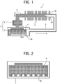
- FIG. 1 is a schematic explanatory view illustrating an example of the loop heat pipe 1 according to the present embodiment
- FIG. 2 is a view illustrating a virtual cross section when cut along the a-a section illustrated by the broken line in FIG. 1 .
- the loop heat pipe 1 illustrated in FIG. 1 is filled with a working fluid containing a condensable fluid such as water, alcohol, acetone, or chlorofluorocarbon, and is provided with the following elements.
- the loop heat pipe 1 includes an evaporator 2 that absorbs heat from a heat generator and evaporates the working fluid from a liquid phase to a gas phase, and a condenser 3 that condenses the working fluid in the gas phase led from the evaporator 2 to the liquid phase.
- the loop heat pipe 1 also includes a steam pipe 4 for circulating the working fluid in the gas phase from the evaporator 2 to the condenser 3 and a liquid pipe 5 for circulating the working fluid in the liquid phase from the condenser 3 to the evaporator 2.
- the evaporator 2 is configured by a heat receiver 7 in which a wick 6 is accommodated and a reservoir 8 that stores the working fluid in the liquid phase.
- the condenser 3 is configured by a stainless-made pipe 31 provided with a large number of thin-plate aluminum-made fins 32 on an outer peripheral surface.
- the wick 6 is a porous body having elasticity. Further, a plurality of grooves 10 is provided in a bottom surface in FIG. 1 of the wick 6 from an end portion on the steam pipe 4 side in a direction toward an opposite side.
- the plurality of grooves 10 is provided at equal intervals in the bottom portion of the wick 6 as illustrated in FIG. 2 illustrating a virtual cross section when cut along the a-a section illustrated by the broken line in FIG. 1 .
- the dimensions of the groove 10 are drawn at a ratio larger than an actual size.
- the thickness of the wick 6 is set to a size slightly larger than an inner size of a casing of the heat receiver 7 of the evaporator 2.
- the wick 6 is in close contact with an inner surface of the heat receiver 7 in a state where the wick 6 is accommodated in the heat receiver 7. Further, since the wick 6 is in close contact with the heat receiver 7, the heat of the heat generator is efficiently transmitted to the wick 6 through the casing of the heat receiver 7. Meanwhile, in a portion where the groove 10 is provided, a space is formed between the portion and the casing of the heat receiver 7.
- the wick 6 is configured by a porous body, that is, a porous material, the working fluid in the liquid phase stored in the reservoir 8 permeates into the wick 6 by a capillary phenomenon. Due to this capillary phenomenon, the wick 6 also plays a role of a pump for sending the working fluid in the liquid phase from the condenser 3 to the evaporator 2.
- the working fluid a condensable fluid such as water, alcohol, acetone, or chlorofluorocarbon is used. Further, the working fluid favorably has good wettability with the wick 6 so as to be able to permeate into the wick 6. The wettability can be measured by a contact angle between the wick 6 and the working fluid. Since the working fluid cannot permeate into the wick 6 if the contact angle is 90° or higher, the contact angle needs to be less than 90°.
- the working fluid evaporates and changes to the gas phase by the heat.
- the working fluid that has evaporated and changed to the gas phase is sent to the steam pipe 4 through the grooves 10. Then, the working fluid in the gas phase is sent to the condenser 3 through the steam pipe 4.
- the heat of the working fluid passing through the inside (pipe 31) is released to the outside through the fins 32, so that the temperature of the working fluid is lowered, and the working fluid is condensed and changes from the gas phase to the liquid phase.
- the working fluid that has changed to the liquid phase moves to the evaporator 2 through the liquid pipe 5, and permeates again from the reservoir 8 into the wick 6 provided inside the heat receiver 7 by the capillary phenomenon.
- the heat of the heat generator is continuously released to the outside, and an object to be cooled is cooled.
- FIG. 3 is a schematic explanatory view of a conventional general loop heat pipe 100.
- the loop heat pipe 100 includes an evaporator 102 that receives heat from an outside and evaporates a working fluid from a liquid phase to a gas phase, and a condenser 103 that radiates heat to the outside to condense the working fluid from the gas phase to the liquid phase. Further, the loop heat pipe 100 also includes a steam pipe 104 for circulating the working fluid in the gas phase from the evaporator 102 to the condenser 103 and a liquid pipe 105 for circulating the working fluid in the liquid phase from the condenser 103 to the evaporator 102.
- a wick 106 configured by a porous body (porous material) is accommodated inside the evaporator 102, and the working fluid in the liquid phase sent from the liquid pipe 105 permeate in fine holes in the wick 106 by the capillary phenomenon to bleed out to an outer surface of the wick 106.
- the heat from a heat generator (object to be cooled) in contact with the evaporator 102 is transmitted to the wick 106 through a casing of the evaporator 102, so that the working fluid evaporates by the heat and changes to the gas phase.
- the working fluid that has changed to the gas phase moves to the condenser 103 through the steam pipe 104.
- the heat of the working fluid is released to the outside, so that the temperature of the working fluid is decreased and changed to the liquid phase. Then, the working fluid that has changed to the liquid phase moves to the evaporator 102 through the liquid pipe 105 and again permeates into the wick 106. As described above, the loop heat pipe 100 circulates the working fluid using the phase change of the working fluid to transfer the heat absorbed in the evaporator 102 to the condenser 103, thereby efficiently cooling the object to be cooled.
- the wick 106 is required to have high permeability.
- JP2011-247462-A JP5699452-B
- JP2011-247462-A JP5699452-B
- JP2011-247462-A JP5699452-B
- JP2011-247462-A JP5699452-B
- JP2011-247462-A JP5699452-B
- JP2011-247462-A JP5699452-B
- JP2011-247462-A JP5699452-B
- JP5699452-B describes a loop heat pipe in which a metal pattern is formed on an outer surface of a wick and the metal pattern and an inner wall of a casing of an evaporator is diffusion-bonded to integrate the wick and the casing, and occurrence of gaps between joint surfaces is prevented by thermal or mechanical stress.
- JP2011-190996-A describes the following loop heat pipe.
- a inner groove extending in a length direction is formed in an inner surface of a wick, in addition to an outer groove formed in an outer surface of the wick. Then, when the wick is pressed into and accommodated in a casing of an evaporator and deformed to close the inner groove, collapse of a hole in a vicinity of an outer peripheral surface is suppressed even if a manufacturing error occurs in an outer diameter dimension of the wick.
- wicks in which obtainment of an evaporator with poor performance due to collapse of pores in the vicinity of the outer peripheral surface of the wick and non-favorable contact of an outer surface of the wick with an inner surface of the casing of the evaporator can be suppressed, can be mass-produced in a stable manner.
- the wick 6 used for the loop heat pipe 1 is configured by porous rubber such as foamed silicone rubber that is the porous body.
- porous rubber such as foamed silicone rubber that is the porous body.
- the heat transfer efficiency from the casing of the evaporator 2 to the wick 6 can be favorably obtained, and the cooling performance of the loop heat pipe 1 is improved.
- the porous body in the present embodiment can be obtained applying a technology proposed with water-foamed silicone rubber, for example.
- stirring is performed such that bubbles present in cross section obtained when a foam formed in a sampling manner is cut are present as follows.
- the stirring is performed such that bubbles present in cross section have a size in a range from 0.1 ⁇ m to 50 ⁇ m, both inclusive, and bubbles having a pore size from 5 ⁇ m to 10 ⁇ m, both inclusive, are most present.
- the above-described porous body is obtained by mixing a catalyst, a surfactant, and a crosslinking agent with commercially available two-component liquid silicone rubber.
- the liquid silicone rubber is mixed and stirred with a mixed solution obtained by mixing an additive, a filler, a dispersant, and the like in water (with an alcohol if required) to have viscosity equivalent to the viscosity of the liquid silicone rubber, to prepare an emulsion composition.
- the liquid silicone rubber favorably has specific gravity of 1.00 to 1.05 g/cm 3 in consideration of emulsifying properties with water.
- a blending ratio of the liquid silicone rubber and the mixed solution varies depending on porosity to be obtained.
- the blending ratio of the liquid silicone rubber and the mixed solution is set to 1:1, particulate water in the emulsion evaporates and becomes a void, so a foam having the porosity of 50% can be obtained.
- a homogenizer or a stirrer with ultrasonic treatment is used as required, and various stirring conditions such as stirring means, stirring time, and stirring speed (for example, 300 to 1500 rpm) are adjusted to obtain a bubble distribution that satisfies the above-described conditions.
- the prepared emulsion composition is filled in a mold and heated to perform primary heating for curing silicone rubber without evaporating water in the emulsion composition.
- the primary heating is performed in the condition that a heating temperature is in a range of 80 to 130°C and a heating time is in a range of 30 to 120 minutes.
- the heating temperature is favorably 90 to 110°C and the heating time is favorably 60 to 90 minutes.
- secondary heating is performed to remove moisture from the foam after the primary heating.
- the secondary heating is performed in the condition that the heating temperature is 150 to 300°C and the heating time is 1 to 24 hours.
- the heating temperature is favorably 200 to 250°C and the heating time is favorably 3 to 8 hours.
- the porous body used for the wick 6 has the function to move the working fluid by the capillary force to drive the loop heat pipe 1, the pore size of the porous body is favorably small to obtain larger capillary force.
- pore size pore radius of the wick: rwick
- capillary force capillary pressure: ⁇ Pcap
- ⁇ is surface tension of the working fluid
- ⁇ is a contact angle between the wick and the working fluid
- the capillary pressure becomes larger as the pore radius of the wick is smaller. Further, to operate the loop heat pipe 1, the capillary force (capillary pressure: ⁇ Pcap) and a total pressure loss: ⁇ Ptotal need to satisfy the following Inequality 2. ⁇ Pcap ⁇ ⁇ Ptotal
- ⁇ Ptotal ⁇ Pwick + ⁇ Pgroov + ⁇ PVL + ⁇ Pcond + ⁇ PLL + ⁇ Pgrav
- ⁇ Pwick is a pressure loss of the wick
- ⁇ Pgroov is a pressure loss of the groove
- ⁇ PVL is a pressure loss of the steam pipe
- ⁇ Pcond is a pressure loss of the condenser
- ⁇ PLL is a pressure loss of the liquid pipe
- ⁇ Pgrav is a pressure loss due to gravity.
- a pore size peak of the porous body is favorably smaller, is specifically favorably 50 ⁇ m or smaller.
- the pore size peak is favorably 30 ⁇ m or smaller, and more favorably 10 ⁇ m or smaller.
- the wick can be made to function even with the thickness of 1 ⁇ m or smaller or 0.1 ⁇ m or smaller, but a lower limit value is favorably 0.1 ⁇ m or larger.
- the pore size peak can be determined by capturing the cross section of the porous body with a laser microscope and measuring the area of the holes by image processing of an obtained image.
- the porosity of the porous body used for the wick 6 is more advantageous for driving the loop heat pipe 1.
- the porosity of the porous body is favorably 20% or larger. When the porosity is less than 20%, driving of the loop heat pipe 1 becomes difficult. More favorably, the porosity is 50% or larger.
- the porosity can be calculated by the following Equation 4.
- the porosity % the specific gravity of the porous body ⁇ the specific gravity of solid / the specific gravity of solid ⁇ 100
- a communication hole of the wick 6 refers to a portion where bubbles (cells) communicate with each other and a portion where the capillary force for driving the working fluid acts.
- the diameter of the communication hole (communication hole diameter) is favorably 10 ⁇ m or smaller, and more favorably 5 ⁇ m or smaller.
- an average pore size of the communication holes is favorably set to 3 ⁇ m or smaller, so that the wick 6 itself can more favorably achieve both the high capillary force and permeability.
- the communication hole can be made to function even with the diameter of 1 ⁇ m or smaller or 0.1 ⁇ m or smaller.
- the diameter of the communication hole is measured by a bubble point method, and an obtained maximum pore size is adopted as the communication hole diameter.
- gas pressure is applied to the porous body completely immersed in a test solution, and the pressure at which appearance of bubbles is recognized is adopted as a bubble point.
- d is the maximum pore size
- ⁇ is the surface tension of the working fluid
- ⁇ is the contact angle between the wick and the working fluid
- ⁇ P is the pressure loss.
- FIG. 5 is an explanatory diagram of specifications and test results of samples of examples and comparative examples used for cooling performance test.
- a plurality of samples of the examples of the wick 6 was prepared with water-foamed silicone rubber, and samples of the comparative examples of the wick 6 were prepared with water-foamed silicone rubber, chemically-foamed silicone rubber, water-foamed urethane rubber, metal, and ceramic. Then, a cooling performance test by a single device in a case of using each prepared sample for the loop heat pipe 1 was performed.
- Example 1 a water-foamed silicone rubber material with an activator and a polymer selected to be composite cell (composite) was used for both the examples, the amount of water was adjusted, and two types of Example 1 with the porosity of 70% and Example 2 with the porosity of 65% were prepared.
- FIG. 6 is a view of the sample of the wick 6 of Example 1 in a bubble state observed (captured) with a laser microscope, and it can be confirmed that the bubbles are adjacent to each other and have a composite shape.
- FIG. 7 is a view of bubbles of the sample of the wick 6 of Example 1 further enlarged and observed by a scanning electron microscope, and communication holes of 5 ⁇ m or smaller connecting the bubbles can be confirmed.
- FIG. 8 is a graph illustrating results of measuring pore size distributions of representative samples of the wick 6 used in the examples and comparative examples used for the cooling performance test, and illustrates results after processing images of the representative samples with a laser microscope and measuring the pore size distributions.
- Example 3 a water-foamed urethane rubber was used to obtain a composite cell (composite).
- the pore size range ⁇ m and the porosity % are equivalent to the case of using the water-foamed silicone rubber of Examples 1 and 2 and the cooling performance is ranked third but a heat resistance characteristic is up to about 120°C. For this reason, heat resistance was defect (poor) and cannot be used depending on a cooling application. Therefore, comprehensive judgment (judgment) was also defect (poor).
- the pore size range ⁇ m of the sample was in the range from 0.1 ⁇ m to 50 ⁇ m, both inclusive, the peak of the pore size distribution of the sample (pore size peak ⁇ m) was 10 um, and the communication hole diameter (communication hole ⁇ m) was 2 ⁇ m.
- the wick 6 was configured by urethane rubber, high adhesion (good) was obtained by producing the wick 6 slightly larger than the inner dimension of the casing of the heat receiver 7 of the evaporator 2 using elasticity of the urethane rubber.
- the thick solid line illustrates the distribution of the sample of Example 1 that is the composite cell
- the thin solid line illustrates the distribution of the water-foamed silicone rubber of Comparative Example 1 that is a single foam (single cell)
- the broken line illustrates the distribution of the chemically-foamed silicone rubber of Comparative Example 2 that is the single foam.
- the distribution of the pore size ⁇ m is expressed by a probability density function and is in a relationship of probability density of a vertical axis Y to the pore size ⁇ m of a horizontal axis X.
- the number (frequency) of bubbles in a certain pore size range ⁇ m is calculated like sieving. In all the bubbles present in an image processing range, the number (probability) of bubbles present in the certain pore size range ⁇ m is obtained.
- the distribution of the sample of Example 1 is a fine pore size distribution with the bubbles (pore size range) of a range from 0.1 ⁇ m to 50 ⁇ m, both inclusive, and the peak of the distribution of the sample of Example 1 is 5 ⁇ m.
- the pore size range ⁇ m of the sample was in the range from 0.1 ⁇ m to 50 um, both inclusive, the peak of the pore size distribution of the sample (pore size peak ⁇ m) was 5 um, and the communication hole diameter (communication hole ⁇ m) was 2 ⁇ m.
- the water-foamed silicone rubber of Examples 1 and 2 causes a dehydration reaction of a water phase simultaneously with crosslinking of rubber at the time of secondary heating, the communication holes between bubbles are efficiently formed due to the composite cell, and both the permeability and expression of the capillary force by the fine communication holes can be achieved. Further, high adhesion (good) was obtained by producing the wick 6 to be slightly larger than the inner diameter of the casing (case) of the heat receiver 7 of the evaporator 2 using the elasticity of silicone rubber, and the cooling efficiency was improved.
- Example 1 was ranked first and Example 2 was ranked third in the cooling performance, which are favorable, and it is considered that the difference in the permeability was exhibited in the performance.
- the heat resistance was also favorable (good), and the comprehensive judgment (judgment) was also favorable (good).
- Example 3 using the water-foamed urethane rubber material, the pore size range ⁇ m was in the range from 0.1 ⁇ m to 50 um, both inclusive, the peak of the pore size distribution of the sample (pore size peak ⁇ m) was 10 um, and the communication hole diameter (communication hole ⁇ m) was 2 ⁇ m.
- Example 3 was also very favorable in the cooling performance and was ranked third in the cooling performance.
- the heat resistance was poor and becomes defect (poor) depending on a cooling application and cannot be used.
- Comparative Example 1 a water-foamed silicone rubber material was used to obtain a single cell (single foam).
- the bubble have a size in a range from 0.1 ⁇ m to 50 ⁇ m, both inclusive, but the pore size peak is 20 um, which is larger than the pore size peak in Examples 1 and 2. Because the material has a large pore diameter, the porosity can be increased up to 60%, and the cooling performance was worse than in Examples 1 and 2, and the cooling performance rank was ranked sixth, so the comprehensive judgment (judgment) was defect (poor).
- the wick 6 was configured by silicone rubber, high adhesion (good) was obtained and the heat resistance was favorable (good) by producing the wick 6 slightly larger than the inner dimension of the casing of the heat receiver 7 of the evaporator 2 using elasticity of the silicone rubber.
- Comparative Example 2 a chemically-foamed silicone rubber material was used to obtain a single cell (single foam). Since chemical foaming does not basically form a communication hole, bubbles were caused to communicate by being broken by being drawn with a metal roller. However, forming the fine communication hole is difficult by the foam breaking. As a result, the cooling performance was poor and the cooling performance was ranked seventh, and the comprehensive judgment (judgment) was defect (poor).
- the pore size range ⁇ m was in a range from 30 ⁇ m to 200 um, both inclusive, the peak of the pore size distribution of the sample (pore size peak ⁇ m) was 80 um, the porosity was 70%, and the communication hole diameter (communication hole ⁇ m) was 2 ⁇ m.
- the wick 6 was configured by silicone rubber, high adhesion (good) was obtained and the heat resistance was favorable (good) by producing the wick 6 slightly larger than the inner dimension of the casing of the heat receiver 7 of the evaporator 2 using elasticity of the silicone rubber.
- Comparative Examples 3 and 4 a metal (steel use stainless (SUS)) was used in Comparative Example 3 and a ceramic (alumina) was used in Comparative Example 4 to be sintered samples (sintered connection).
- SUS steel use stainless
- a ceramic alumina
- Comparative Example 3 was ranked second and Comparative Example 4 was ranked fifth in the cooling performance, and both Comparative Examples 3 and 4 were worse than Example 1 in the cooling performance.
- the pore size ranges ⁇ m of the samples were in the range from 0.1 ⁇ m to 50 ⁇ m, both inclusive, and the peak of the pore size distribution of the sample (pore size peak ⁇ m) was 6 ⁇ m in Comparative Example 3 and 10 ⁇ m in Comparative Example 4. Further, the porosity % was 70% both in Comparative Examples 3 and 4, and the communication hole diameter (communication hole ⁇ m) was 2 ⁇ m in Comparative Example 3 and 10 ⁇ m in Comparative Example 4.
- the bubbles present in cross section had a size in a range from 0.1 ⁇ m to 50 um, both inclusive, the composite cells were present, and among the composite cells, bubbles having the pore size from 5 ⁇ m to 10 um, both inclusive, were most present, and the communication holes of 5 ⁇ m or smaller were included between the bubbles.
- cooling performance of the loop heat pipe 1 Further improvement of the cooling performance of the loop heat pipe 1 can be implemented. Specifically, the cooling performance was ranked first to third.
- Comparative Example 1 was ranked sixth and Comparative Example 2 was ranked seventh in the cooling performance. Further, a point of the sintered connection of SUS (metal) falls outside the first specifications in Comparative Example 3 and the cooling performance was ranked second, and two points of the sintered connection of alumina (ceramic) and the communication hole of exceeding 5 ⁇ m fall outside the first specifications in Comparative Example 4 and the cooling performance was ranked fifth.
- the porous body is configured by the foamed silicone rubber, specifically, by the water-foamed silicone rubber in Examples 1 and 2 and Comparative Example 1 and by the chemically-foamed silicone rubber in Comparative Example 2.
- the elasticity and heat resistance can be imparted to the wick 6.
- Example 3 the porous body is configured by foamed urethane rubber (water-foamed urethane rubber) and the adhesion is improved by imparting the elasticity.
- the heat resistance characteristic is up to 120°C.
- Comparative Example 3 is configured by the metal (SUS)
- Comparative Example 4 is configured by the ceramic (alumina), and both have heat resistance but have poor elasticity, and require high precision processing to make the adhesion favorable, and are evaluated to be defective from the viewpoint of cost.
- the porous body is configured by the water-foamed silicone rubber.
- the porous body was configured by the chemically-foamed silicone rubber, and the pore diameter range was 30 to 200 ⁇ m, the pore size peak was 80 ⁇ m, and the communication hole was 20 um, and it has been found that both the fine pore size and favorable communication cannot be achieved.
- Examples 1 and 2 satisfying all of the first specifications, the second specifications, and the third specifications have very favorable cooling performance, and can provide a cooling device including a roller achieving the adhesion and heat resistance to the casing.
- the configuration provided with one evaporator 2 and one condenser 3 has been described.
- the configuration of the loop heat pipe of the present embodiment is not limited to such a configuration.
- the present embodiment is also applicable to a loop heat pipe provided with the evaporator 2 and the condenser 3, the number of at least one of which is two or more.
- a wick such as the wick 6 configured by a porous body such as a porous elastic body used in a cooler such as the loop heat pipe 1 including an evaporator such as the evaporator 2 (heat receiver 7) that changes a working fluid such as a condensable fluid from a liquid phase to a gas phase and a condenser such as the condenser 3 that changes the working fluid from the gas phase to the liquid phase, and provided in the evaporator, in which a plurality of bubbles present in cross section obtained when the porous body is cut has sizes in a range from 0.1 ⁇ m to 50 um, both inclusive, a plurality of composite cells formed by spherical bubbles partially overlapping each other is present, and among the plurality of composite cells, bubbles having pore sizes from 5 ⁇ m to 10 um, both inclusive, are most present, and a plurality of communication holes of 5 ⁇ m or smaller is present between the bubbles.
- the porous body configuring the wick of the present aspect is manufactured such that the bubbles and the communication holes present in a cross section obtained when the porous body is cut satisfy the above-described specifications, thus allowing the porous body itself to achieve both higher capillary force and higher permeability than before.
- the porous body itself configuring the wick can achieve both the higher capillary force and higher permeability than before, further improvement of cooling performance of the cooler can be implemented.
- the wick enabling implementation of further improvement of the cooling performance of the cooler can be provided.
- an average pore size of the communication holes is equal to or smaller than 3 ⁇ m.
- the wick itself can more favorably achieve both the high capillary force and high permeability.
- the porous body is made of foamed silicone rubber.
- configuring the porous body by foamed silicone rubber can impart elasticity and heat resistance.
- the foamed silicone rubber is water-foamed silicone rubber.
- configuring the foamed silicone rubber by water-foamed silicone rubber can achieve both a fine pore size and favorable communication.
- a loop heat pipe such as the loop heat pipe 1 including an evaporator such as the evaporator 2 (heat receiver 7) that changes a working fluid such as a condensable fluid from a liquid phase to a gas phase and a condenser such as the condenser 3 that changes the working fluid from the gas phase to the liquid phase, in which the wick such as the wick 6 according to any one of Aspect A to Aspect D is provided inside the evaporator.
- the loop heat pipe implementing high cooling performance can be provided.
- a cooling device such as a cooler of the electronic device (projector) 20 includes a loop heat pipe including an evaporator such as the evaporator 2 (heat receiver 7) that changes a working fluid such as a condensable fluid from a liquid phase to a gas phase and a condenser such as the condenser 3 that changes the working fluid from the gas phase to the liquid phase.
- a loop heat pipe such as the loop heat pipe 1 according to Aspect E is used as the loop heat pipe.
- the cooling device having high cooling performance can be provided.
- An electronic device including a cooler includes a loop heat pipe such as the loop heat pipe 1 of Aspect E as the cooler.
- the electronic device including required cooling performance can be provided.
- a method for manufacturing a porous body such as a porous elastic body used in a cooler such as the loop heat pipe 1 including an evaporator such as the evaporator 2 (heat receiver 7) that changes a working fluid such as a condensable fluid from a liquid phase to a gas phase and a condenser that changes the working fluid from the gas phase to the liquid phase, and provided in the evaporator.
- a working fluid such as a condensable fluid from a liquid phase to a gas phase
- a condenser that changes the working fluid from the gas phase to the liquid phase
- the method includes manufacturing the porous body such that a plurality of bubbles present in a cross section obtained when the porous body is cut has a size in a range from 0.1 ⁇ m to 50 ⁇ m, both inclusive, a plurality of composite cells formed by spherical bubbles partially overlapping each other is present, and among the plurality of composite cells, bubbles having a pore size from 5 ⁇ m to 10 um, both inclusive, are most present, and a plurality of communication holes of 5 ⁇ m or smaller is present between the plurality of bubbles.
- the porous body manufacturing method is manufactured such that the bubbles and the communication holes present in cross section obtained when the manufactured porous body is cut satisfy the above-described specifications.
- the porous body that can achieve both higher capillary force and higher permeability than before can be manufactured.
- the porous body itself configuring the wick can achieve both the higher capillary force and higher permeability than before, further improvement of the cooling performance of the cooler using the wick configured by the porous body can be implemented.
- porous body manufacturing method for manufacturing the porous body configuring the wick enabling implementation of further improvement of the cooling performance of the cooler can be provided.
- the method includes manufacturing the porous body such that a plurality of bubbles present in a cross section obtained when the porous body is cut has a size in a range from 0.1 ⁇ m to 50 um, both inclusive, a plurality of composite cells formed by spherical bubbles partially overlapping each other is present, and among the plurality of composite cells, bubbles having a pore size from 5 ⁇ m to 10 um, both inclusive, are most present, and a plurality of communication holes of 5 ⁇ m or smaller is present between the plurality of bubbles.
- the wick manufactured by the wick manufacturing method of the present aspect is manufactured such that the bubbles and the communication holes present in cross section obtained when the porous body configuring the wick is cut satisfy the above-described specifications.
- the manufactured wick itself can achieve both the higher capillary force and higher permeability than before.
- the wick itself thus manufactured can achieve both the higher capillary force and higher permeability than before, further improvement of the cooling performance of the cooler using the wick can be implemented.
- the wick manufacturing method for manufacturing the wick enabling implementation of further improvement of the cooling performance of the cooler can be provided.
Landscapes
- Engineering & Computer Science (AREA)
- Physics & Mathematics (AREA)
- Thermal Sciences (AREA)
- Mechanical Engineering (AREA)
- General Engineering & Computer Science (AREA)
- Life Sciences & Earth Sciences (AREA)
- Sustainable Development (AREA)
- Microelectronics & Electronic Packaging (AREA)
- Chemical & Material Sciences (AREA)
- Dispersion Chemistry (AREA)
- Cooling Or The Like Of Semiconductors Or Solid State Devices (AREA)
- Cooling Or The Like Of Electrical Apparatus (AREA)
Abstract
Description
- The present invention relates to a wick, a loop heat pipe, a cooling device, an electronic device, a method of manufacturing a porous body, and a method of manufacturing wick.
- Conventionally, there is known a wick configured by a porous body used in a cooler such as a loop heat pipe including an evaporator that changes a working fluid from a liquid phase to a gas phase and a condenser that changes the working fluid from the gas phase to the liquid phase, and provided inside the evaporator.
- For example,
JP2018-109497-A - The wick is a cylindrical hollow member configured by porous rubber and closed at one end side, and has a plurality of grooves formed in a direction perpendicular to a circumferential direction of an outer peripheral surface in contact with a casing of the evaporator, the grooves transporting a working fluid changed in a gas phase. This wick is provided inside the evaporator. Specifically, the wick larger than an inner diameter of a cylindrical internal space of the casing of the evaporator that includes the wick is pressed into the casing of the evaporator.
- Further, specifications (specification and conditions at the time of manufacturing) of a porous bubble structure of the porous rubber configuring this wick are favorably an average pore diameter of 50 µm or smaller, porosity of from 20 to 80%, both inclusive, and a continuous foam rate of from 25 to 100%, both inclusive.
- With these configurations, securement of adhesion of the wick to an inner surface of a casing of the evaporator and suppression of local collapse of holes in the vicinity of an outer peripheral surface of the wick can be easily performed, and favorable cooling performance can be obtained.
- However, in recent years, the demand for further improvement of the cooling performance of the cooler used for electronic devices and the like has increased more than before.
- In an aspect of the present invention, there is provided a wick includes a porous body. The porous body includes a plurality of bubbles, a plurality of composite cells, and a plurality of communication holes. The plurality of bubbles has sizes in a range from 0.1 µm to 50 um, both inclusive, in a cross section obtained when the porous body is cut. The plurality of composite cells is formed by spherical bubbles partially overlapping each other. Bubbles of pore sizes from 5 µm to 10 µm, both inclusive, are most present among the plurality of composite cells. The plurality of communication holes of 5 µm or smaller are between the plurality of bubbles.
- In another aspect of the present invention, there is provided a loop heat pipe that includes an evaporator, a condenser, and the wick. The evaporator is configured to change a working fluid from a liquid phase to a gas phase. The condenser is configured to change the working fluid from the gas phase to the liquid phase. The wick is disposed inside the evaporator.
- In still another aspect of the present invention, there is provided a cooling device that includes the loop heat pipe.
- In still yet another aspect of the present disclosure, there is provided an electronic device that includes the loop heat pipe as a cooler.
- According to the present invention, the wick enabling implementation of further improvement of the cooling performance of the cooler can be provided.
- The aforementioned and other aspects, features, and advantages of the present disclosure would be better understood by reference to the following detailed description when considered in connection with the accompanying drawings, wherein:
-
FIG. 1 is a schematic explanatory view illustrating an example of a loop heat pipe according to an embodiment; -
FIG. 2 is a view illustrating a virtual cross section when cut along the a-a section illustrated by the broken line inFIG. 1 ; -
FIG. 3 is a schematic explanatory view of a conventional general loop heat pipe; -
FIG. 4 is a schematic explanatory view illustrating another example of the loop heat pipe provided in an electronic device according to the embodiment; -
FIG. 5 is an explanatory diagram of specifications and test results of samples of examples and comparative examples used for cooling performance test; -
FIG. 6 is a view of a bubble state of a sample of a wick of Example 1 observed by a laser microscope; -
FIG. 7 is a view of bubbles of the sample of the wick of Example 1 further enlarged and observed by a scanning electron microscope; and -
FIG. 8 is a graph illustrating pore size distribution of representative samples of wicks used for examples and comparative examples used for cooling performance test. - The accompanying drawings are intended to depict embodiments of the present disclosure and should not be interpreted to limit the scope thereof. The accompanying drawings are not to be considered as drawn to scale unless explicitly noted.
- In describing embodiments illustrated in the drawings, specific terminology is employed for the sake of clarity. However, the disclosure of this patent specification is not intended to be limited to the specific terminology so selected and it is to be understood that each specific element includes all technical equivalents that operate in a similar manner and achieve similar results.
- Although the embodiments are described with technical limitations with reference to the attached drawings, such description is not intended to limit the scope of the disclosure and all of the components or elements described in the embodiments of this disclosure are not necessarily indispensable.
- Referring now to the drawings, embodiments of the present disclosure are described below. In the drawings for explaining the following embodiments, the same reference codes are allocated to elements (members or components) having the same function or shape and redundant descriptions thereof are omitted below.
- Hereinafter, an embodiment of a loop heat pipe (hereinafter referred to as loop heat pipe 1) will be described using drawings as appropriate, as a cooler including an evaporator provided with a wick to which the present invention is applied in an inside and a condenser.
- Here, in the drawings for describing the present embodiment, description of constituent elements such as members or constituent parts having the same function or shape are provided with the same reference numerals as long as the constituent elements are distinguishable. Further, after once described, description of the constituent elements provided with the same reference numerals is appropriately omitted.
-
FIG. 1 is a schematic explanatory view illustrating an example of theloop heat pipe 1 according to the present embodiment, andFIG. 2 is a view illustrating a virtual cross section when cut along the a-a section illustrated by the broken line inFIG. 1 . - The
loop heat pipe 1 illustrated inFIG. 1 is filled with a working fluid containing a condensable fluid such as water, alcohol, acetone, or chlorofluorocarbon, and is provided with the following elements. Theloop heat pipe 1 includes anevaporator 2 that absorbs heat from a heat generator and evaporates the working fluid from a liquid phase to a gas phase, and acondenser 3 that condenses the working fluid in the gas phase led from theevaporator 2 to the liquid phase. Further, theloop heat pipe 1 also includes asteam pipe 4 for circulating the working fluid in the gas phase from theevaporator 2 to thecondenser 3 and aliquid pipe 5 for circulating the working fluid in the liquid phase from thecondenser 3 to theevaporator 2. Theevaporator 2 is configured by aheat receiver 7 in which awick 6 is accommodated and areservoir 8 that stores the working fluid in the liquid phase. - One end portion of the
steam pipe 4 is coupled to theheat receiver 7, and one end portion of theliquid pipe 5 is coupled to thereservoir 8. Further, the other end portions of thesteam pipe 4 and theliquid pipe 5 are coupled to thecondenser 3. Thecondenser 3 is configured by a stainless-madepipe 31 provided with a large number of thin-plate aluminum-madefins 32 on an outer peripheral surface. - The
wick 6 is a porous body having elasticity. Further, a plurality ofgrooves 10 is provided in a bottom surface inFIG. 1 of thewick 6 from an end portion on thesteam pipe 4 side in a direction toward an opposite side. - The plurality of
grooves 10 is provided at equal intervals in the bottom portion of thewick 6 as illustrated inFIG. 2 illustrating a virtual cross section when cut along the a-a section illustrated by the broken line inFIG. 1 . Here, inFIG. 2 , the dimensions of thegroove 10 are drawn at a ratio larger than an actual size. Further, the thickness of thewick 6 is set to a size slightly larger than an inner size of a casing of theheat receiver 7 of theevaporator 2. - By setting the thickness of the
wick 6 as described above, thewick 6 is in close contact with an inner surface of theheat receiver 7 in a state where thewick 6 is accommodated in theheat receiver 7. Further, since thewick 6 is in close contact with theheat receiver 7, the heat of the heat generator is efficiently transmitted to thewick 6 through the casing of theheat receiver 7. Meanwhile, in a portion where thegroove 10 is provided, a space is formed between the portion and the casing of theheat receiver 7. - Since the
wick 6 is configured by a porous body, that is, a porous material, the working fluid in the liquid phase stored in thereservoir 8 permeates into thewick 6 by a capillary phenomenon. Due to this capillary phenomenon, thewick 6 also plays a role of a pump for sending the working fluid in the liquid phase from thecondenser 3 to theevaporator 2. - As the working fluid, a condensable fluid such as water, alcohol, acetone, or chlorofluorocarbon is used. Further, the working fluid favorably has good wettability with the
wick 6 so as to be able to permeate into thewick 6. The wettability can be measured by a contact angle between thewick 6 and the working fluid. Since the working fluid cannot permeate into thewick 6 if the contact angle is 90° or higher, the contact angle needs to be less than 90°. - In the
loop heat pipe 1 according to the present embodiment, when the heat from the heat generator is transmitted to the working fluid in the liquid phase in thewick 6 through the casing of the evaporator 2 (the heat receiver 7), the working fluid evaporates and changes to the gas phase by the heat. The working fluid that has evaporated and changed to the gas phase is sent to thesteam pipe 4 through thegrooves 10. Then, the working fluid in the gas phase is sent to thecondenser 3 through thesteam pipe 4. - In the
condenser 3, the heat of the working fluid passing through the inside (pipe 31) is released to the outside through thefins 32, so that the temperature of the working fluid is lowered, and the working fluid is condensed and changes from the gas phase to the liquid phase. The working fluid that has changed to the liquid phase moves to theevaporator 2 through theliquid pipe 5, and permeates again from thereservoir 8 into thewick 6 provided inside theheat receiver 7 by the capillary phenomenon. By such circulation of the working fluid, the heat of the heat generator is continuously released to the outside, and an object to be cooled is cooled. - Here, disadvantage of a conventional loop heat pipe provided with a wick inside an evaporator will be described with reference to the drawing.
-
FIG. 3 is a schematic explanatory view of a conventional generalloop heat pipe 100. - Generally, as illustrated in
FIG. 3 , theloop heat pipe 100 includes anevaporator 102 that receives heat from an outside and evaporates a working fluid from a liquid phase to a gas phase, and acondenser 103 that radiates heat to the outside to condense the working fluid from the gas phase to the liquid phase. Further, theloop heat pipe 100 also includes asteam pipe 104 for circulating the working fluid in the gas phase from theevaporator 102 to thecondenser 103 and aliquid pipe 105 for circulating the working fluid in the liquid phase from thecondenser 103 to theevaporator 102. - A wick 106 configured by a porous body (porous material) is accommodated inside the
evaporator 102, and the working fluid in the liquid phase sent from theliquid pipe 105 permeate in fine holes in the wick 106 by the capillary phenomenon to bleed out to an outer surface of the wick 106. At this time, the heat from a heat generator (object to be cooled) in contact with theevaporator 102 is transmitted to the wick 106 through a casing of theevaporator 102, so that the working fluid evaporates by the heat and changes to the gas phase. Then, the working fluid that has changed to the gas phase moves to thecondenser 103 through thesteam pipe 104. - In the
condenser 103, the heat of the working fluid is released to the outside, so that the temperature of the working fluid is decreased and changed to the liquid phase. Then, the working fluid that has changed to the liquid phase moves to theevaporator 102 through theliquid pipe 105 and again permeates into the wick 106. As described above, theloop heat pipe 100 circulates the working fluid using the phase change of the working fluid to transfer the heat absorbed in theevaporator 102 to thecondenser 103, thereby efficiently cooling the object to be cooled. - Here, to improve cooling efficiency, adhesion with the
evaporator 102 needs to be secured and the working fluid is circulated by the capillary force of the wick 106, and to minimize a pressure loss, the wick 106 is required to have high permeability. - To solve such problems,
JP2011-247462-A JP5699452-B - Further, configuring the wick with a resin material and making an outer diameter of the wick slightly larger than an inner diameter of the casing is a common method for ensuring favorable adhesion of the wick to the casing. However, if the outer diameter of the wick becomes excessively large due to a manufacturing error, when the wick is accommodated in the casing and compressed, a hole in a vicinity of the outer surface of the wick collapses, so that the flow of the working fluid may be impeded and cooling performance may be reduced. To solve the problem,
JP2011-190996-A - A inner groove extending in a length direction is formed in an inner surface of a wick, in addition to an outer groove formed in an outer surface of the wick. Then, when the wick is pressed into and accommodated in a casing of an evaporator and deformed to close the inner groove, collapse of a hole in a vicinity of an outer peripheral surface is suppressed even if a manufacturing error occurs in an outer diameter dimension of the wick.
- Then, with these configurations, wicks, in which obtainment of an evaporator with poor performance due to collapse of pores in the vicinity of the outer peripheral surface of the wick and non-favorable contact of an outer surface of the wick with an inner surface of the casing of the evaporator can be suppressed, can be mass-produced in a stable manner.
- However, in the wick described in
JP2011-190996-A - Therefore, specifications (specifications and conditions at the time of manufacturing) of a wick enabling implementation of further improvement of the cooling performance of a cooler are studied for the
wick 6 of the present embodiment. - Next, the
wick 6 provided inside the heat receiver 7 (evaporator 2) of theloop heat pipe 1 of the present embodiment will be described in detail. - As described above, the
wick 6 used for theloop heat pipe 1 according to the present embodiment is configured by porous rubber such as foamed silicone rubber that is the porous body. By configuring thewick 6 with the porous rubber as described above, higher elastic force than the elastic force of a porous resin can be obtained. Therefore, the adhesion of thewick 6 to the casing (heat receiver 7) of theevaporator 2 is increased. - With the configuration, the heat transfer efficiency from the casing of the
evaporator 2 to thewick 6 can be favorably obtained, and the cooling performance of theloop heat pipe 1 is improved. - Further, as described above, securement of high adhesion and suppression of local collapse of holes of the
wick 6 can be implemented by a measure of configuring thewick 6 with the porous rubber. Therefore, if post-processing of transport grooves (grooves) such as thegrooves 10 for transporting the working fluid (evaporation refrigerant) can be omitted, the manufacturing cost can be further reduced. - Although various methods can be considered as a method for manufacturing the wick configured by an elastic porous body, that is, a porous elastic body, the porous body in the present embodiment can be obtained applying a technology proposed with water-foamed silicone rubber, for example.
- Specifically, using a water-foamed silicone rubber composition, stirring is performed such that bubbles present in cross section obtained when a foam formed in a sampling manner is cut are present as follows. The stirring is performed such that bubbles present in cross section have a size in a range from 0.1 µm to 50 µm, both inclusive, and bubbles having a pore size from 5 µm to 10 µm, both inclusive, are most present.
- More specifically, the above-described porous body is obtained by mixing a catalyst, a surfactant, and a crosslinking agent with commercially available two-component liquid silicone rubber. The liquid silicone rubber is mixed and stirred with a mixed solution obtained by mixing an additive, a filler, a dispersant, and the like in water (with an alcohol if required) to have viscosity equivalent to the viscosity of the liquid silicone rubber, to prepare an emulsion composition. The liquid silicone rubber favorably has specific gravity of 1.00 to 1.05 g/cm3 in consideration of emulsifying properties with water.
- Here, a blending ratio of the liquid silicone rubber and the mixed solution varies depending on porosity to be obtained. For example, when the blending ratio of the liquid silicone rubber and the mixed solution is set to 1:1, particulate water in the emulsion evaporates and becomes a void, so a foam having the porosity of 50% can be obtained. For the emulsion, a homogenizer or a stirrer with ultrasonic treatment is used as required, and various stirring conditions such as stirring means, stirring time, and stirring speed (for example, 300 to 1500 rpm) are adjusted to obtain a bubble distribution that satisfies the above-described conditions.
- Thereafter, the prepared emulsion composition is filled in a mold and heated to perform primary heating for curing silicone rubber without evaporating water in the emulsion composition.
- Here, the primary heating is performed in the condition that a heating temperature is in a range of 80 to 130°C and a heating time is in a range of 30 to 120 minutes. The heating temperature is favorably 90 to 110°C and the heating time is favorably 60 to 90 minutes. Next, secondary heating is performed to remove moisture from the foam after the primary heating. The secondary heating is performed in the condition that the heating temperature is 150 to 300°C and the heating time is 1 to 24 hours. The heating temperature is favorably 200 to 250°C and the heating time is favorably 3 to 8 hours. By performing such secondary heating, the moisture is removed from the porous body, and bubbles are formed into a continuous bubble type to become a composite cell formed by spherical bubbles partially overlapping each other, and final cure of the silicone rubber is terminated.
- Next, specifications (specifications and conditions at the time of manufacturing) of the cross section, which can be obtained by cutting the water-foamed silicone rubber as the porous body for which the final cure has been terminated, will be described in more detail.
- Since the porous body used for the
wick 6 has the function to move the working fluid by the capillary force to drive theloop heat pipe 1, the pore size of the porous body is favorably small to obtain larger capillary force. - The pore size (pore radius of the wick: rwick) and capillary force (capillary pressure: ΔPcap) of the porous body used for the
wick 6 are expressed using the followingEquation 1.
- Here, σ is surface tension of the working fluid, and θ is a contact angle between the wick and the working fluid.
- As can be seen from
Equation 1 above, the capillary pressure becomes larger as the pore radius of the wick is smaller. Further, to operate theloop heat pipe 1, the capillary force (capillary pressure: ΔPcap) and a total pressure loss: ΔPtotal need to satisfy the followingInequality 2.
- Further, the total pressure loss: ΔPtotal can then be obtained using
Equation 3.
- As described above, to obtain larger capillary force, a pore size peak of the porous body is favorably smaller, is specifically favorably 50 µm or smaller. When the pore size peak is larger than 50 µm, obtainment of capillary force sufficient to drive the loop heat pipe is difficult. The pore size peak is favorably 30 µm or smaller, and more favorably 10 µm or smaller.
- In a case where the thickness of the wick is extremely thin, the wick can be made to function even with the thickness of 1 µm or smaller or 0.1 µm or smaller, but a lower limit value is favorably 0.1 µm or larger.
- Here, the pore size peak can be determined by capturing the cross section of the porous body with a laser microscope and measuring the area of the holes by image processing of an obtained image.
- Higher porosity of the porous body used for the
wick 6 is more advantageous for driving theloop heat pipe 1. Specifically, the porosity of the porous body is favorably 20% or larger. When the porosity is less than 20%, driving of theloop heat pipe 1 becomes difficult. More favorably, the porosity is 50% or larger. The porosity can be calculated by the followingEquation 4.
- A communication hole of the
wick 6 refers to a portion where bubbles (cells) communicate with each other and a portion where the capillary force for driving the working fluid acts. To obtain the cooling performance, the diameter of the communication hole (communication hole diameter) is favorably 10 µm or smaller, and more favorably 5 µm or smaller. Further, an average pore size of the communication holes is favorably set to 3 µm or smaller, so that thewick 6 itself can more favorably achieve both the high capillary force and permeability. - Note that, in a case where the thickness of the
wick 6 is extremely thin, the communication hole can be made to function even with the diameter of 1 µm or smaller or 0.1 µm or smaller. - The diameter of the communication hole is measured by a bubble point method, and an obtained maximum pore size is adopted as the communication hole diameter.
- Here, gas pressure is applied to the porous body completely immersed in a test solution, and the pressure at which appearance of bubbles is recognized is adopted as a bubble point. Moreover, the maximum pore size is calculated using the following
Equation 5 using a test solution with known surface tension.
- Here, d is the maximum pore size, σ is the surface tension of the working fluid, θ is the contact angle between the wick and the working fluid, and ΔP is the pressure loss.
- Next, cooling performance tests performed by setting examples within main numerical ranges and comparative examples out of the numerical ranges, of the above-described conditions of the
wick 6, will be appropriately described with reference to the drawings. - (1) Description of an electronic device (projector) 20 favorably provided with a wick used in a cooling performance test.
FIG. 4 is a schematic explanatory view illustrating another example of theloop heat pipe 1 provided in theelectronic device 20 according to the present embodiment.
Further, another example of theloop heat pipe 1 illustrated inFIG. 4 is an example in which a wick slightly larger than an inner diameter of a cylindrical internal space of the casing (case) of theevaporator 2 is press-fitted into the casing of the evaporator, unlike the example illustrated inFIG. 1 .
Note that, as the cooler of the electronic device according to the present embodiment, theloop heat pipe 1 illustrated inFIG. 1 can be used instead of the loop heat pipe illustrated inFIG. 4 . However, the loop heat pipe illustrated inFIG. 4 is used for the cooling performance tests of the examples and comparative examples described below.
Theelectronic device 20 illustrated inFIG. 4 is a projector including anoptical unit 21. The projector is an example of an electronic device to which the present embodiment is applied.
Here, the electronic device to which theloop heat pipe 1 according to the present embodiment can be applied is not limited to the projector. Theloop heat pipe 1 can be applied to various electronic devices such as an image forming device such as a printer, a copier, a facsimile, or a multifunction peripheral of the aforementioned functions, a personal computer, a server, an electronic blackboard, a television, a Blu-ray recorder, and a game machine, in addition to the projector.
Further, theloop heat pipe 1 and the cooling device according to the present embodiment can be applied to devices other than the electronic devices. For example, theloop heat pipe 1 and the cooling device according to the present embodiment may be applied to a cooling device for cooling a chemical plant or the like equipped with a reaction furnace, or to a container or a building attached to an electronic device such as a server rack.
The evaporator 2 (in particular, the heat receiver 7) of theloop heat pipe 1 illustrated inFIG. 4 is disposed in contact with a heat generator of theoptical unit 21. Theevaporator 2 absorbs heat from the heat generator to cool the object to be cooled (heat generator, the optical unit, or the projector).
Thecondenser 3 is disposed in the vicinity of anexhaust fan 22 provided on a side surface of a casing of a projector main body. When theexhaust fan 22 discharges the air to the outside, an air flow is generated around thecondenser 3, thecondenser 3 is cooled by the air flow, and heat dissipation effect in thecondenser 3 is improved.
Further, anair supply port 23 is provided in the side opposite to the side surface of the casing where theexhaust fan 22 is provided, and the air taken in through theair supply port 23 passes through the inside of the projector and is discharged from theexhaust fan 22. In the example illustrated inFIG. 4 , theloop heat pipe 1 and theexhaust fan 22 for enhancing the heat dissipation effect of theloop heat pipe 1 are provided as a cooling device for cooling the projector. A blower fan for blowing the air to thecondenser 3 may be provided instead of theexhaust fan 22. Further, a cooling device provided with theloop heat pipe 1 without the fan may be adopted. - (2) Detailed description of examples and comparative examples.
-
FIG. 5 is an explanatory diagram of specifications and test results of samples of examples and comparative examples used for cooling performance test. - In the present test, as illustrated in
FIG. 5 , a plurality of samples of the examples of thewick 6 was prepared with water-foamed silicone rubber, and samples of the comparative examples of thewick 6 were prepared with water-foamed silicone rubber, chemically-foamed silicone rubber, water-foamed urethane rubber, metal, and ceramic. Then, a cooling performance test by a single device in a case of using each prepared sample for theloop heat pipe 1 was performed. - In Examples 1 and 2, a water-foamed silicone rubber material with an activator and a polymer selected to be composite cell (composite) was used for both the examples, the amount of water was adjusted, and two types of Example 1 with the porosity of 70% and Example 2 with the porosity of 65% were prepared.
-
FIG. 6 is a view of the sample of thewick 6 of Example 1 in a bubble state observed (captured) with a laser microscope, and it can be confirmed that the bubbles are adjacent to each other and have a composite shape. -
FIG. 7 is a view of bubbles of the sample of thewick 6 of Example 1 further enlarged and observed by a scanning electron microscope, and communication holes of 5 µm or smaller connecting the bubbles can be confirmed. -
FIG. 8 is a graph illustrating results of measuring pore size distributions of representative samples of thewick 6 used in the examples and comparative examples used for the cooling performance test, and illustrates results after processing images of the representative samples with a laser microscope and measuring the pore size distributions. - In Example 3, a water-foamed urethane rubber was used to obtain a composite cell (composite). The pore size range µm and the porosity % are equivalent to the case of using the water-foamed silicone rubber of Examples 1 and 2 and the cooling performance is ranked third but a heat resistance characteristic is up to about 120°C. For this reason, heat resistance was defect (poor) and cannot be used depending on a cooling application. Therefore, comprehensive judgment (judgment) was also defect (poor).
- Here, as illustrated in
FIG. 5 , in Example 3, the pore size range µm of the sample was in the range from 0.1 µm to 50 µm, both inclusive, the peak of the pore size distribution of the sample (pore size peak µm) was 10 um, and the communication hole diameter (communication hole µm) was 2 µm. - Since the
wick 6 was configured by urethane rubber, high adhesion (good) was obtained by producing thewick 6 slightly larger than the inner dimension of the casing of theheat receiver 7 of theevaporator 2 using elasticity of the urethane rubber. - In the graph in
FIG. 8 , the thick solid line illustrates the distribution of the sample of Example 1 that is the composite cell, the thin solid line illustrates the distribution of the water-foamed silicone rubber of Comparative Example 1 that is a single foam (single cell), and the broken line illustrates the distribution of the chemically-foamed silicone rubber of Comparative Example 2 that is the single foam. Here, the distribution of the pore size µm is expressed by a probability density function and is in a relationship of probability density of a vertical axis Y to the pore size µm of a horizontal axis X. In image processing, the number (frequency) of bubbles in a certain pore size range µm is calculated like sieving. In all the bubbles present in an image processing range, the number (probability) of bubbles present in the certain pore size range µm is obtained. - As illustrated in
FIG. 8 , in the distribution of the sample of Example 1 that is the composite cell, the following facts can be confirmed, as compared with the distributions of the water-foamed silicone rubber of Comparative Example 1 and the chemically-foamed silicone rubber of Comparative Example 2 of other single foams. It can be confirmed that the distribution of the sample of Example 1 is a fine pore size distribution with the bubbles (pore size range) of a range from 0.1 µm to 50 µm, both inclusive, and the peak of the distribution of the sample of Example 1 is 5 µm. - Further, as illustrated in
FIG. 5 , in each of Examples 1 and 2, the pore size range µm of the sample was in the range from 0.1 µm to 50 um, both inclusive, the peak of the pore size distribution of the sample (pore size peak µm) was 5 um, and the communication hole diameter (communication hole µm) was 2 µm. - Although the water-foamed silicone rubber of Examples 1 and 2 causes a dehydration reaction of a water phase simultaneously with crosslinking of rubber at the time of secondary heating, the communication holes between bubbles are efficiently formed due to the composite cell, and both the permeability and expression of the capillary force by the fine communication holes can be achieved. Further, high adhesion (good) was obtained by producing the
wick 6 to be slightly larger than the inner diameter of the casing (case) of theheat receiver 7 of theevaporator 2 using the elasticity of silicone rubber, and the cooling efficiency was improved. As a result, the cooling performance was very favorable both in Examples 1 and 2 and was particularly favorable in Example 1 with high porosity %, and Example 1 was ranked first and Example 2 was ranked third in the cooling performance, which are favorable, and it is considered that the difference in the permeability was exhibited in the performance. - Further, since the
wick 6 was configured by silicone rubber, the heat resistance was also favorable (good), and the comprehensive judgment (judgment) was also favorable (good). - Here, as for Example 3 using the water-foamed urethane rubber material, the pore size range µm was in the range from 0.1 µm to 50 um, both inclusive, the peak of the pore size distribution of the sample (pore size peak µm) was 10 um, and the communication hole diameter (communication hole µm) was 2 µm.Therefore, similarly to Examples 1 and 2, Example 3 was also very favorable in the cooling performance and was ranked third in the cooling performance. However, as described above, the heat resistance was poor and becomes defect (poor) depending on a cooling application and cannot be used.
- In Comparative Example 1, a water-foamed silicone rubber material was used to obtain a single cell (single foam). The bubble have a size in a range from 0.1 µm to 50 µm, both inclusive, but the pore size peak is 20 um, which is larger than the pore size peak in Examples 1 and 2. Because the material has a large pore diameter, the porosity can be increased up to 60%, and the cooling performance was worse than in Examples 1 and 2, and the cooling performance rank was ranked sixth, so the comprehensive judgment (judgment) was defect (poor).
- Since the
wick 6 was configured by silicone rubber, high adhesion (good) was obtained and the heat resistance was favorable (good) by producing thewick 6 slightly larger than the inner dimension of the casing of theheat receiver 7 of theevaporator 2 using elasticity of the silicone rubber. - In Comparative Example 2, a chemically-foamed silicone rubber material was used to obtain a single cell (single foam). Since chemical foaming does not basically form a communication hole, bubbles were caused to communicate by being broken by being drawn with a metal roller. However, forming the fine communication hole is difficult by the foam breaking. As a result, the cooling performance was poor and the cooling performance was ranked seventh, and the comprehensive judgment (judgment) was defect (poor).
- Further, as illustrated in
FIG. 5 , in Comparative Example 2, the pore size range µm was in a range from 30 µm to 200 um, both inclusive, the peak of the pore size distribution of the sample (pore size peak µm) was 80 um, the porosity was 70%, and the communication hole diameter (communication hole µm) was 2 µm. - Since the
wick 6 was configured by silicone rubber, high adhesion (good) was obtained and the heat resistance was favorable (good) by producing thewick 6 slightly larger than the inner dimension of the casing of theheat receiver 7 of theevaporator 2 using elasticity of the silicone rubber. - In Comparative Examples 3 and 4, a metal (steel use stainless (SUS)) was used in Comparative Example 3 and a ceramic (alumina) was used in Comparative Example 4 to be sintered samples (sintered connection). By controlling sintering conditions and particle diameters, the pore size range µm is equivalent and the pore size peak and the porosity % are substantially equivalent to the case of using the water-foamed silicone rubber in Examples 1 and 2 and the case of using the water-foamed urethane rubber in Example 3.
- However, since both the materials are hard, very high precision is required to obtain adhesion with the casing (adhesion was poor), so the comprehensive judgment (judgment) was also defect (poor). Further, the problem is that the unit price is high for mass production.
- Further, an efficiency decrease due to heat leak occurs because of higher thermal conductivity than thermal conductivity of silicone rubber. Therefore, Comparative Example 3 was ranked second and Comparative Example 4 was ranked fifth in the cooling performance, and both Comparative Examples 3 and 4 were worse than Example 1 in the cooling performance.
- Note that the metal (SUS) was used in Comparative Example 3 and the ceramic (alumina) was used in Comparative Example 4 so that the
wicks 6 become the sintered samples. Therefore, the heat resistance was favorable (good). - Here, as illustrated in
FIG. 5 , in Comparative Examples 3 and 4, the pore size ranges µm of the samples were in the range from 0.1 µm to 50 µm, both inclusive, and the peak of the pore size distribution of the sample (pore size peak µm) was 6 µm in Comparative Example 3 and 10 µm in Comparative Example 4. Further, the porosity % was 70% both in Comparative Examples 3 and 4, and the communication hole diameter (communication hole µm) was 2 µm in Comparative Example 3 and 10 µm in Comparative Example 4. - From the results of the cooling performance test using the above-described samples of Examples 1 to 3 and Comparative Examples 1 to 4, the following effects have been able to be confirmed according to the specifications of the bubbles, the communication holes, and the like present in cross section obtained when the porous body configuring the
wick 6 of the present embodiment was cut. - The bubbles present in cross section had a size in a range from 0.1 µm to 50 um, both inclusive, the composite cells were present, and among the composite cells, bubbles having the pore size from 5 µm to 10 um, both inclusive, were most present, and the communication holes of 5 µm or smaller were included between the bubbles.
- Further improvement of the cooling performance of the
loop heat pipe 1 can be implemented. Specifically, the cooling performance was ranked first to third. - Here, one point of the single foam falls outside the first specifications in Comparative Example 1, and three points of the single foam, the pore size range of 30 to 200 um, and the communication hole of exceeding 5 µm fall outside the first specifications in Comparative Example 2. Comparative Example 1 was ranked sixth and Comparative Example 2 was ranked seventh in the cooling performance. Further, a point of the sintered connection of SUS (metal) falls outside the first specifications in Comparative Example 3 and the cooling performance was ranked second, and two points of the sintered connection of alumina (ceramic) and the communication hole of exceeding 5 µm fall outside the first specifications in Comparative Example 4 and the cooling performance was ranked fifth.
- From the comparison, it has been confirmed that the wick itself can more favorably achieve both the high capillary force and permeability because the cooling performance is ranked lower as the number of points falling outside the specifications satisfied by Examples 1 and 2 becomes larger, and the average pore size of the communication holes is 3 µm or smaller, except Comparative Example 3 using SUS.
- The porous body is configured by the foamed silicone rubber, specifically, by the water-foamed silicone rubber in Examples 1 and 2 and Comparative Example 1 and by the chemically-foamed silicone rubber in Comparative Example 2.
- The elasticity and heat resistance can be imparted to the
wick 6. - Here, in Example 3, the porous body is configured by foamed urethane rubber (water-foamed urethane rubber) and the adhesion is improved by imparting the elasticity. However, as described above, the heat resistance characteristic is up to 120°C. Further, Comparative Example 3 is configured by the metal (SUS), and Comparative Example 4 is configured by the ceramic (alumina), and both have heat resistance but have poor elasticity, and require high precision processing to make the adhesion favorable, and are evaluated to be defective from the viewpoint of cost.
- The porous body is configured by the water-foamed silicone rubber.
- By changing the foamed silicone rubber to the water-foamed silicone rubber, both the fine pore size and favorable communication can be achieved.
- Here, in Comparative Example 2, the porous body was configured by the chemically-foamed silicone rubber, and the pore diameter range was 30 to 200 µm, the pore size peak was 80µm, and the communication hole was 20 um, and it has been found that both the fine pore size and favorable communication cannot be achieved.
- As described above, it has been confirmed that Examples 1 and 2 satisfying all of the first specifications, the second specifications, and the third specifications have very favorable cooling performance, and can provide a cooling device including a roller achieving the adhesion and heat resistance to the casing.
- Although the present embodiment has been described with reference to the drawings, the specific configuration is not limited to the configuration of the
loop heat pipe 1 provided with thewick 6 of the above-described embodiment, and design change and the like not deviating from the gist may be made. - For example, in the
loop heat pipe 1 of the present embodiment described with reference toFIGS. 1, 2 , and4 , the configuration provided with oneevaporator 2 and onecondenser 3 has been described. However, the configuration of the loop heat pipe of the present embodiment is not limited to such a configuration. The present embodiment is also applicable to a loop heat pipe provided with theevaporator 2 and thecondenser 3, the number of at least one of which is two or more. - Further, in the
loop heat pipe 1 of the present embodiment described with reference toFIGS. 1, 2 , and4 , the configuration provided with onewick 6 inside theevaporator 2 has been described. However, the present embodiment is also applicable to a configuration provided with a plurality of wicks in parallel. - The above description is merely examples, and a specific effect is exerted in each of the following modes.
- A wick such as the
wick 6 configured by a porous body such as a porous elastic body used in a cooler such as theloop heat pipe 1 including an evaporator such as the evaporator 2 (heat receiver 7) that changes a working fluid such as a condensable fluid from a liquid phase to a gas phase and a condenser such as thecondenser 3 that changes the working fluid from the gas phase to the liquid phase, and provided in the evaporator, in which a plurality of bubbles present in cross section obtained when the porous body is cut has sizes in a range from 0.1 µm to 50 um, both inclusive, a plurality of composite cells formed by spherical bubbles partially overlapping each other is present, and among the plurality of composite cells, bubbles having pore sizes from 5 µm to 10 um, both inclusive, are most present, and a plurality of communication holes of 5 µm or smaller is present between the bubbles. - According to this configuration, the following effects can be exerted.
- The porous body configuring the wick of the present aspect is manufactured such that the bubbles and the communication holes present in a cross section obtained when the porous body is cut satisfy the above-described specifications, thus allowing the porous body itself to achieve both higher capillary force and higher permeability than before.
- As described above, since the porous body itself configuring the wick can achieve both the higher capillary force and higher permeability than before, further improvement of cooling performance of the cooler can be implemented.
- Therefore, the wick enabling implementation of further improvement of the cooling performance of the cooler can be provided.
- In Aspect A, an average pore size of the communication holes is equal to or smaller than 3 µm.
- According to this aspect, the wick itself can more favorably achieve both the high capillary force and high permeability.
- In Aspect A or Aspect B, the porous body is made of foamed silicone rubber.
- According to this aspect, configuring the porous body by foamed silicone rubber can impart elasticity and heat resistance.
- In Aspect C, the foamed silicone rubber is water-foamed silicone rubber.
- According to this aspect, configuring the foamed silicone rubber by water-foamed silicone rubber can achieve both a fine pore size and favorable communication.
- A loop heat pipe such as the
loop heat pipe 1 including an evaporator such as the evaporator 2 (heat receiver 7) that changes a working fluid such as a condensable fluid from a liquid phase to a gas phase and a condenser such as thecondenser 3 that changes the working fluid from the gas phase to the liquid phase, in which the wick such as thewick 6 according to any one of Aspect A to Aspect D is provided inside the evaporator. - According to this aspect, the loop heat pipe implementing high cooling performance can be provided.
- A cooling device such as a cooler of the electronic device (projector) 20 includes a loop heat pipe including an evaporator such as the evaporator 2 (heat receiver 7) that changes a working fluid such as a condensable fluid from a liquid phase to a gas phase and a condenser such as the
condenser 3 that changes the working fluid from the gas phase to the liquid phase. In the cooling device, a loop heat pipe such as theloop heat pipe 1 according to Aspect E is used as the loop heat pipe. - According to this aspect, the cooling device having high cooling performance can be provided.
- An electronic device including a cooler includes a loop heat pipe such as the
loop heat pipe 1 of Aspect E as the cooler. - According to this aspect, the electronic device including required cooling performance can be provided.
- A method for manufacturing a porous body such as a porous elastic body used in a cooler such as the
loop heat pipe 1 including an evaporator such as the evaporator 2 (heat receiver 7) that changes a working fluid such as a condensable fluid from a liquid phase to a gas phase and a condenser that changes the working fluid from the gas phase to the liquid phase, and provided in the evaporator. The method includes manufacturing the porous body such that a plurality of bubbles present in a cross section obtained when the porous body is cut has a size in a range from 0.1 µm to 50 µm, both inclusive, a plurality of composite cells formed by spherical bubbles partially overlapping each other is present, and among the plurality of composite cells, bubbles having a pore size from 5 µm to 10 um, both inclusive, are most present, and a plurality of communication holes of 5 µm or smaller is present between the plurality of bubbles. - According to this configuration, the following effects can be exerted.
- In the porous body manufacturing method according to the present aspect, the porous body is manufactured such that the bubbles and the communication holes present in cross section obtained when the manufactured porous body is cut satisfy the above-described specifications. Thus, the porous body that can achieve both higher capillary force and higher permeability than before can be manufactured.
- As described above, since the porous body itself configuring the wick can achieve both the higher capillary force and higher permeability than before, further improvement of the cooling performance of the cooler using the wick configured by the porous body can be implemented.
- Therefore, the porous body manufacturing method for manufacturing the porous body configuring the wick enabling implementation of further improvement of the cooling performance of the cooler can be provided.
- A wick manufacturing method for manufacturing a wick such as the
wick 6 configured by a porous body such as a porous elastic body used in a cooler such as theloop heat pipe 1 including an evaporator such as the evaporator 2 (heat receiver 7) that changes a working fluid such as a condensable fluid from a liquid phase to a gas phase and a condenser such as thecondenser 3 that changes the working fluid from the gas phase to the liquid phase, and provided in the evaporator. The method includes manufacturing the porous body such that a plurality of bubbles present in a cross section obtained when the porous body is cut has a size in a range from 0.1 µm to 50 um, both inclusive, a plurality of composite cells formed by spherical bubbles partially overlapping each other is present, and among the plurality of composite cells, bubbles having a pore size from 5 µm to 10 um, both inclusive, are most present, and a plurality of communication holes of 5 µm or smaller is present between the plurality of bubbles. - According to this configuration, the following effects can be exerted.
The wick manufactured by the wick manufacturing method of the present aspect is manufactured such that the bubbles and the communication holes present in cross section obtained when the porous body configuring the wick is cut satisfy the above-described specifications. Thus, the manufactured wick itself can achieve both the higher capillary force and higher permeability than before. - As described above, since the wick itself thus manufactured can achieve both the higher capillary force and higher permeability than before, further improvement of the cooling performance of the cooler using the wick can be implemented.
- Therefore, the wick manufacturing method for manufacturing the wick enabling implementation of further improvement of the cooling performance of the cooler can be provided.
Claims (7)
- A wick (6) comprising a porous body,
the porous body including:a plurality of bubbles having sizes in a range from 0.1 µm to 50 um, both inclusive, in a cross section obtained when the porous body is cut;a plurality of composite cells formed by spherical bubbles partially overlapping each other, bubbles of pore sizes from 5 µm to 10 um, both inclusive, being most present among the plurality of composite cells; anda plurality of communication holes of 5 µm or smaller between the plurality of bubbles. - The wick (6) according to claim 1,
wherein an average pore size of the plurality of communication holes is equal to or smaller than 3 µm. - The wick (6) according to claim 1 or 2,
wherein the porous body includes foamed silicone rubber. - The wick (6) according to claim 3,
wherein the foamed silicone rubber is water-foamed silicone rubber. - A loop heat pipe (1) comprising:an evaporator (2) configured to change a working fluid from a liquid phase to a gas phase;a condenser (3) configured to change the working fluid from the gas phase to the liquid phase; andthe wick (6) according to any one of claims 1 to 4 disposed inside the evaporator (2).
- A cooling device comprising the loop heat pipe (1) according to claim 5.
- An electronic device (20) comprising the loop heat pipe (1) according to claim 5 as a cooler (1).
Applications Claiming Priority (1)
| Application Number | Priority Date | Filing Date | Title |
|---|---|---|---|
| JP2018142655A JP2020020495A (en) | 2018-07-30 | 2018-07-30 | Wick, loop-type heat pipe, cooling device, electronic apparatus, porous body manufacturing method, and wick manufacturing method |
Publications (2)
| Publication Number | Publication Date |
|---|---|
| EP3605004A1 true EP3605004A1 (en) | 2020-02-05 |
| EP3605004B1 EP3605004B1 (en) | 2022-04-06 |
Family
ID=67439135
Family Applications (1)
| Application Number | Title | Priority Date | Filing Date |
|---|---|---|---|
| EP19188695.1A Active EP3605004B1 (en) | 2018-07-30 | 2019-07-26 | Wick, loop heat pipe, cooling device, electronic device |
Country Status (4)
| Country | Link |
|---|---|
| US (1) | US20200033068A1 (en) |
| EP (1) | EP3605004B1 (en) |
| JP (1) | JP2020020495A (en) |
| CN (1) | CN110779366A (en) |
Families Citing this family (11)
| Publication number | Priority date | Publication date | Assignee | Title |
|---|---|---|---|---|
| JP7350434B2 (en) * | 2019-08-09 | 2023-09-26 | 矢崎エナジーシステム株式会社 | Structure and its manufacturing method |
| US12007171B1 (en) * | 2020-03-31 | 2024-06-11 | Triad National Security, Llc | Heat pipe wick formation |
| EP3917297B1 (en) * | 2020-05-25 | 2025-03-19 | ABB Schweiz AG | Electronics enclosure arrangement for an electric device and an electric device |
| JP7514442B2 (en) * | 2020-07-21 | 2024-07-11 | 株式会社リコー | Wick, evaporator, loop type heat pipe, cooling device, electronic device, and wick manufacturing method |
| EP4019252A1 (en) * | 2020-12-23 | 2022-06-29 | ABB Schweiz AG | Heat-transfer device and method to produce such a device |
| IT202100004793A1 (en) * | 2021-03-02 | 2022-09-02 | Wieland Provides SRL | MICRO-CHANNEL HEAT EXCHANGER |
| JP7678976B2 (en) * | 2021-03-03 | 2025-05-19 | 株式会社リコー | Wick, evaporator, loop type heat pipe, cooling device, electronic device, and wick manufacturing method |
| JP7666033B2 (en) | 2021-03-12 | 2025-04-22 | 株式会社リコー | Wick |
| CN113865392A (en) * | 2021-09-14 | 2021-12-31 | 浙江大学 | a heat sink |
| US20230184498A1 (en) * | 2021-12-14 | 2023-06-15 | Amulaire Thermal Technology, Inc. | Immersion-type heat dissipation substrate having microporous structure |
| US20230025921A1 (en) * | 2022-09-30 | 2023-01-26 | Intel Corporation | Cold plates and liquid cooling systems for electronic devices |
Citations (9)
| Publication number | Priority date | Publication date | Assignee | Title |
|---|---|---|---|---|
| JPH09119789A (en) * | 1995-10-24 | 1997-05-06 | Mitsubishi Materials Corp | Heat pipe manufacturing method |
| JP2003148887A (en) * | 2001-11-15 | 2003-05-21 | Mitsubishi Materials Corp | Heat pipe and manufacturing method thereof |
| US20100294475A1 (en) * | 2009-05-22 | 2010-11-25 | General Electric Company | High performance heat transfer device, methods of manufacture thereof and articles comprising the same |
| JP2011190996A (en) | 2010-03-15 | 2011-09-29 | Fujitsu Ltd | Loop type heat pipe, wick, and information processing device |
| JP2011247462A (en) | 2010-05-25 | 2011-12-08 | Fujitsu Ltd | Loop type heat pipe and evaporator manufacturing method of the loop type heat pipe |
| US20120279068A1 (en) * | 2009-04-07 | 2012-11-08 | University Of Central Florida Research Foundation, Inc. | Hydrophilic particle enhanced heat exchange |
| CN105928403A (en) * | 2016-04-28 | 2016-09-07 | 安徽工业大学 | Powder-microfiber composite porous capillary core applicable to loop heat pipe system |
| EP3343161A1 (en) * | 2016-12-28 | 2018-07-04 | Ricoh Company Ltd. | Loop heat pipe wick, loop heat pipe, cooling device, and electronic device, and method for manufacturing porous rubber and method for manufacturing loop heat pipe wick |
| JP2018109497A (en) | 2016-12-28 | 2018-07-12 | 株式会社リコー | Wick, loop heat pipe, cooling device, electronic device, method for producing porous rubber, and method for producing wick for loop heat pipe |
Family Cites Families (4)
| Publication number | Priority date | Publication date | Assignee | Title |
|---|---|---|---|---|
| JP2005300038A (en) * | 2004-04-13 | 2005-10-27 | Sony Corp | Heat transport device, heat transport device manufacturing method, and electronic device |
| CN104422320B (en) * | 2013-08-21 | 2016-04-20 | 英业达科技有限公司 | Heat pipe |
| JP2017227382A (en) * | 2016-06-22 | 2017-12-28 | 日本碍子株式会社 | Wick |
| JP6547732B2 (en) * | 2016-12-13 | 2019-07-24 | トヨタ自動車株式会社 | Evaporator |
-
2018
- 2018-07-30 JP JP2018142655A patent/JP2020020495A/en active Pending
-
2019
- 2019-07-08 CN CN201910608607.0A patent/CN110779366A/en active Pending
- 2019-07-24 US US16/521,019 patent/US20200033068A1/en not_active Abandoned
- 2019-07-26 EP EP19188695.1A patent/EP3605004B1/en active Active
Patent Citations (10)
| Publication number | Priority date | Publication date | Assignee | Title |
|---|---|---|---|---|
| JPH09119789A (en) * | 1995-10-24 | 1997-05-06 | Mitsubishi Materials Corp | Heat pipe manufacturing method |
| JP2003148887A (en) * | 2001-11-15 | 2003-05-21 | Mitsubishi Materials Corp | Heat pipe and manufacturing method thereof |
| US20120279068A1 (en) * | 2009-04-07 | 2012-11-08 | University Of Central Florida Research Foundation, Inc. | Hydrophilic particle enhanced heat exchange |
| US20100294475A1 (en) * | 2009-05-22 | 2010-11-25 | General Electric Company | High performance heat transfer device, methods of manufacture thereof and articles comprising the same |
| JP2011190996A (en) | 2010-03-15 | 2011-09-29 | Fujitsu Ltd | Loop type heat pipe, wick, and information processing device |
| JP2011247462A (en) | 2010-05-25 | 2011-12-08 | Fujitsu Ltd | Loop type heat pipe and evaporator manufacturing method of the loop type heat pipe |
| JP5699452B2 (en) | 2010-05-25 | 2015-04-08 | 富士通株式会社 | Loop type heat pipe and evaporator manufacturing method for loop type heat pipe |
| CN105928403A (en) * | 2016-04-28 | 2016-09-07 | 安徽工业大学 | Powder-microfiber composite porous capillary core applicable to loop heat pipe system |
| EP3343161A1 (en) * | 2016-12-28 | 2018-07-04 | Ricoh Company Ltd. | Loop heat pipe wick, loop heat pipe, cooling device, and electronic device, and method for manufacturing porous rubber and method for manufacturing loop heat pipe wick |
| JP2018109497A (en) | 2016-12-28 | 2018-07-12 | 株式会社リコー | Wick, loop heat pipe, cooling device, electronic device, method for producing porous rubber, and method for producing wick for loop heat pipe |
Also Published As
| Publication number | Publication date |
|---|---|
| JP2020020495A (en) | 2020-02-06 |
| US20200033068A1 (en) | 2020-01-30 |
| EP3605004B1 (en) | 2022-04-06 |
| CN110779366A (en) | 2020-02-11 |
Similar Documents
| Publication | Publication Date | Title |
|---|---|---|
| EP3605004B1 (en) | Wick, loop heat pipe, cooling device, electronic device | |
| EP3343161B1 (en) | Loop heat pipe wick, loop heat pipe, cooling device, and electronic device, and method for manufacturing porous rubber and method for manufacturing loop heat pipe wick | |
| JP2018109497A (en) | Wick, loop heat pipe, cooling device, electronic device, method for producing porous rubber, and method for producing wick for loop heat pipe | |
| US11371783B2 (en) | Loop heat pipe, cooling device, and electronic device | |
| EP3943869B1 (en) | Wick, evaporator, loop heat pipe, cooling device, electronic device, and method of manufacturing wick | |
| US12453049B2 (en) | Loop heat pipe, cooling system, electronic equipment, and wick | |
| CN115031557B (en) | Capillary wicks and their manufacturing methods, evaporators, loop heat pipes, and cooling devices. | |
| JP7205741B2 (en) | Wick, loop heat pipe, cooling device, electronic device, and wick manufacturing method | |
| US8217090B2 (en) | Elastomer porous material and method of producing the same | |
| JP7116912B2 (en) | Wick, loop heat pipe, cooling device, electronic device, and wick manufacturing method | |
| KR101848413B1 (en) | Latent heat regenerative materials with microcapsule structure using paraffin oil and manufacturing method thereof | |
| Marcelino et al. | A review on thermal performance of CuO-water nanofluids applied to heat pipes and their characteristics | |
| US8222309B2 (en) | Elastomer porous material and method of producing the same | |
| US8217089B2 (en) | Elastomer porous material and method of producing the same | |
| EP3587985B1 (en) | Loop heat pipe, cooling device, and electronic device | |
| JP2006308716A (en) | Rotating body for fixing | |
| US20090291351A1 (en) | Apparatus and method for coating a paste containing a water-repellent substance, and method for manufacturing a fuel cell | |
| KR102427955B1 (en) | Phenol foam and method of producing the same | |
| JP2006323229A (en) | Rotating body for fixing | |
| US20160265589A1 (en) | Sliding member | |
| JP2009242535A (en) | Manufacturing method of hard polyurethane foam | |
| JP2025120549A (en) | Clathrate hydrate generator and heat pump system | |
| Nicolette-Baker et al. | Experimental Performance Investigation of New Low-GWP Refrigerants for Use in Two-Phase Evaporative Cooling of Electronics | |
| Luján | Bernardo Luján 1 José Ignacio Huertas 2✉ Email jhuertas@ tec. mx Patricia Vázquez-Villegas 2 Daniel Armas 1 Mauricio Carmona-García |
Legal Events
| Date | Code | Title | Description |
|---|---|---|---|
| PUAI | Public reference made under article 153(3) epc to a published international application that has entered the european phase |
Free format text: ORIGINAL CODE: 0009012 |
|
| STAA | Information on the status of an ep patent application or granted ep patent |
Free format text: STATUS: REQUEST FOR EXAMINATION WAS MADE |
|
| 17P | Request for examination filed |
Effective date: 20190726 |
|
| AK | Designated contracting states |
Kind code of ref document: A1 Designated state(s): AL AT BE BG CH CY CZ DE DK EE ES FI FR GB GR HR HU IE IS IT LI LT LU LV MC MK MT NL NO PL PT RO RS SE SI SK SM TR |
|
| AX | Request for extension of the european patent |
Extension state: BA ME |
|
| RIN1 | Information on inventor provided before grant (corrected) |
Inventor name: HIRAI, ATSUO Inventor name: MOKI, AKIHIKO Inventor name: TANAKA, TAKASHI Inventor name: ENDOH, TAKESHI |
|
| GRAP | Despatch of communication of intention to grant a patent |
Free format text: ORIGINAL CODE: EPIDOSNIGR1 |
|
| STAA | Information on the status of an ep patent application or granted ep patent |
Free format text: STATUS: GRANT OF PATENT IS INTENDED |
|
| RIN1 | Information on inventor provided before grant (corrected) |
Inventor name: HIRAI, ATSUO Inventor name: MOKI, AKIHIKO Inventor name: TANAKA, TAKASHI Inventor name: ENDOH, TAKESHI |
|
| INTG | Intention to grant announced |
Effective date: 20211220 |
|
| RAP3 | Party data changed (applicant data changed or rights of an application transferred) |
Owner name: RICOH COMPANY, LTD. |
|
| GRAS | Grant fee paid |
Free format text: ORIGINAL CODE: EPIDOSNIGR3 |
|
| GRAA | (expected) grant |
Free format text: ORIGINAL CODE: 0009210 |
|
| STAA | Information on the status of an ep patent application or granted ep patent |
Free format text: STATUS: THE PATENT HAS BEEN GRANTED |
|
| AK | Designated contracting states |
Kind code of ref document: B1 Designated state(s): AL AT BE BG CH CY CZ DE DK EE ES FI FR GB GR HR HU IE IS IT LI LT LU LV MC MK MT NL NO PL PT RO RS SE SI SK SM TR |
|
| REG | Reference to a national code |
Ref country code: GB Ref legal event code: FG4D |
|
| REG | Reference to a national code |
Ref country code: CH Ref legal event code: EP |
|
| REG | Reference to a national code |
Ref country code: AT Ref legal event code: REF Ref document number: 1481716 Country of ref document: AT Kind code of ref document: T Effective date: 20220415 |
|
| REG | Reference to a national code |
Ref country code: IE Ref legal event code: FG4D |
|
| REG | Reference to a national code |
Ref country code: DE Ref legal event code: R096 Ref document number: 602019013306 Country of ref document: DE |
|
| REG | Reference to a national code |
Ref country code: LT Ref legal event code: MG9D |
|
| REG | Reference to a national code |
Ref country code: NL Ref legal event code: MP Effective date: 20220406 |
|
| REG | Reference to a national code |
Ref country code: AT Ref legal event code: MK05 Ref document number: 1481716 Country of ref document: AT Kind code of ref document: T Effective date: 20220406 |
|
| PG25 | Lapsed in a contracting state [announced via postgrant information from national office to epo] |
Ref country code: NL Free format text: LAPSE BECAUSE OF FAILURE TO SUBMIT A TRANSLATION OF THE DESCRIPTION OR TO PAY THE FEE WITHIN THE PRESCRIBED TIME-LIMIT Effective date: 20220406 |
|
| PG25 | Lapsed in a contracting state [announced via postgrant information from national office to epo] |
Ref country code: SE Free format text: LAPSE BECAUSE OF FAILURE TO SUBMIT A TRANSLATION OF THE DESCRIPTION OR TO PAY THE FEE WITHIN THE PRESCRIBED TIME-LIMIT Effective date: 20220406 Ref country code: PT Free format text: LAPSE BECAUSE OF FAILURE TO SUBMIT A TRANSLATION OF THE DESCRIPTION OR TO PAY THE FEE WITHIN THE PRESCRIBED TIME-LIMIT Effective date: 20220808 Ref country code: NO Free format text: LAPSE BECAUSE OF FAILURE TO SUBMIT A TRANSLATION OF THE DESCRIPTION OR TO PAY THE FEE WITHIN THE PRESCRIBED TIME-LIMIT Effective date: 20220706 Ref country code: LT Free format text: LAPSE BECAUSE OF FAILURE TO SUBMIT A TRANSLATION OF THE DESCRIPTION OR TO PAY THE FEE WITHIN THE PRESCRIBED TIME-LIMIT Effective date: 20220406 Ref country code: HR Free format text: LAPSE BECAUSE OF FAILURE TO SUBMIT A TRANSLATION OF THE DESCRIPTION OR TO PAY THE FEE WITHIN THE PRESCRIBED TIME-LIMIT Effective date: 20220406 Ref country code: GR Free format text: LAPSE BECAUSE OF FAILURE TO SUBMIT A TRANSLATION OF THE DESCRIPTION OR TO PAY THE FEE WITHIN THE PRESCRIBED TIME-LIMIT Effective date: 20220707 Ref country code: FI Free format text: LAPSE BECAUSE OF FAILURE TO SUBMIT A TRANSLATION OF THE DESCRIPTION OR TO PAY THE FEE WITHIN THE PRESCRIBED TIME-LIMIT Effective date: 20220406 Ref country code: ES Free format text: LAPSE BECAUSE OF FAILURE TO SUBMIT A TRANSLATION OF THE DESCRIPTION OR TO PAY THE FEE WITHIN THE PRESCRIBED TIME-LIMIT Effective date: 20220406 Ref country code: BG Free format text: LAPSE BECAUSE OF FAILURE TO SUBMIT A TRANSLATION OF THE DESCRIPTION OR TO PAY THE FEE WITHIN THE PRESCRIBED TIME-LIMIT Effective date: 20220706 Ref country code: AT Free format text: LAPSE BECAUSE OF FAILURE TO SUBMIT A TRANSLATION OF THE DESCRIPTION OR TO PAY THE FEE WITHIN THE PRESCRIBED TIME-LIMIT Effective date: 20220406 |
|
| PG25 | Lapsed in a contracting state [announced via postgrant information from national office to epo] |
Ref country code: RS Free format text: LAPSE BECAUSE OF FAILURE TO SUBMIT A TRANSLATION OF THE DESCRIPTION OR TO PAY THE FEE WITHIN THE PRESCRIBED TIME-LIMIT Effective date: 20220406 Ref country code: PL Free format text: LAPSE BECAUSE OF FAILURE TO SUBMIT A TRANSLATION OF THE DESCRIPTION OR TO PAY THE FEE WITHIN THE PRESCRIBED TIME-LIMIT Effective date: 20220406 Ref country code: LV Free format text: LAPSE BECAUSE OF FAILURE TO SUBMIT A TRANSLATION OF THE DESCRIPTION OR TO PAY THE FEE WITHIN THE PRESCRIBED TIME-LIMIT Effective date: 20220406 Ref country code: IS Free format text: LAPSE BECAUSE OF FAILURE TO SUBMIT A TRANSLATION OF THE DESCRIPTION OR TO PAY THE FEE WITHIN THE PRESCRIBED TIME-LIMIT Effective date: 20220806 |
|
| REG | Reference to a national code |
Ref country code: DE Ref legal event code: R097 Ref document number: 602019013306 Country of ref document: DE |
|
| PG25 | Lapsed in a contracting state [announced via postgrant information from national office to epo] |
Ref country code: SM Free format text: LAPSE BECAUSE OF FAILURE TO SUBMIT A TRANSLATION OF THE DESCRIPTION OR TO PAY THE FEE WITHIN THE PRESCRIBED TIME-LIMIT Effective date: 20220406 Ref country code: SK Free format text: LAPSE BECAUSE OF FAILURE TO SUBMIT A TRANSLATION OF THE DESCRIPTION OR TO PAY THE FEE WITHIN THE PRESCRIBED TIME-LIMIT Effective date: 20220406 Ref country code: RO Free format text: LAPSE BECAUSE OF FAILURE TO SUBMIT A TRANSLATION OF THE DESCRIPTION OR TO PAY THE FEE WITHIN THE PRESCRIBED TIME-LIMIT Effective date: 20220406 Ref country code: EE Free format text: LAPSE BECAUSE OF FAILURE TO SUBMIT A TRANSLATION OF THE DESCRIPTION OR TO PAY THE FEE WITHIN THE PRESCRIBED TIME-LIMIT Effective date: 20220406 Ref country code: DK Free format text: LAPSE BECAUSE OF FAILURE TO SUBMIT A TRANSLATION OF THE DESCRIPTION OR TO PAY THE FEE WITHIN THE PRESCRIBED TIME-LIMIT Effective date: 20220406 Ref country code: CZ Free format text: LAPSE BECAUSE OF FAILURE TO SUBMIT A TRANSLATION OF THE DESCRIPTION OR TO PAY THE FEE WITHIN THE PRESCRIBED TIME-LIMIT Effective date: 20220406 |
|
| PLBE | No opposition filed within time limit |
Free format text: ORIGINAL CODE: 0009261 |
|
| STAA | Information on the status of an ep patent application or granted ep patent |
Free format text: STATUS: NO OPPOSITION FILED WITHIN TIME LIMIT |
|
| PG25 | Lapsed in a contracting state [announced via postgrant information from national office to epo] |
Ref country code: MC Free format text: LAPSE BECAUSE OF FAILURE TO SUBMIT A TRANSLATION OF THE DESCRIPTION OR TO PAY THE FEE WITHIN THE PRESCRIBED TIME-LIMIT Effective date: 20220406 |
|
| REG | Reference to a national code |
Ref country code: CH Ref legal event code: PL |
|
| 26N | No opposition filed |
Effective date: 20230110 |
|
| REG | Reference to a national code |
Ref country code: BE Ref legal event code: MM Effective date: 20220731 |
|
| PG25 | Lapsed in a contracting state [announced via postgrant information from national office to epo] |
Ref country code: AL Free format text: LAPSE BECAUSE OF FAILURE TO SUBMIT A TRANSLATION OF THE DESCRIPTION OR TO PAY THE FEE WITHIN THE PRESCRIBED TIME-LIMIT Effective date: 20220406 |
|
| PG25 | Lapsed in a contracting state [announced via postgrant information from national office to epo] |
Ref country code: LU Free format text: LAPSE BECAUSE OF NON-PAYMENT OF DUE FEES Effective date: 20220726 Ref country code: LI Free format text: LAPSE BECAUSE OF NON-PAYMENT OF DUE FEES Effective date: 20220731 Ref country code: CH Free format text: LAPSE BECAUSE OF NON-PAYMENT OF DUE FEES Effective date: 20220731 |
|
| PG25 | Lapsed in a contracting state [announced via postgrant information from national office to epo] |
Ref country code: SI Free format text: LAPSE BECAUSE OF FAILURE TO SUBMIT A TRANSLATION OF THE DESCRIPTION OR TO PAY THE FEE WITHIN THE PRESCRIBED TIME-LIMIT Effective date: 20220406 Ref country code: BE Free format text: LAPSE BECAUSE OF NON-PAYMENT OF DUE FEES Effective date: 20220731 |
|
| P01 | Opt-out of the competence of the unified patent court (upc) registered |
Effective date: 20230522 |
|
| PG25 | Lapsed in a contracting state [announced via postgrant information from national office to epo] |
Ref country code: IE Free format text: LAPSE BECAUSE OF NON-PAYMENT OF DUE FEES Effective date: 20220726 |
|
| PG25 | Lapsed in a contracting state [announced via postgrant information from national office to epo] |
Ref country code: IT Free format text: LAPSE BECAUSE OF FAILURE TO SUBMIT A TRANSLATION OF THE DESCRIPTION OR TO PAY THE FEE WITHIN THE PRESCRIBED TIME-LIMIT Effective date: 20220406 |
|
| PG25 | Lapsed in a contracting state [announced via postgrant information from national office to epo] |
Ref country code: HU Free format text: LAPSE BECAUSE OF FAILURE TO SUBMIT A TRANSLATION OF THE DESCRIPTION OR TO PAY THE FEE WITHIN THE PRESCRIBED TIME-LIMIT; INVALID AB INITIO Effective date: 20190726 |
|
| PG25 | Lapsed in a contracting state [announced via postgrant information from national office to epo] |
Ref country code: MK Free format text: LAPSE BECAUSE OF FAILURE TO SUBMIT A TRANSLATION OF THE DESCRIPTION OR TO PAY THE FEE WITHIN THE PRESCRIBED TIME-LIMIT Effective date: 20220406 Ref country code: CY Free format text: LAPSE BECAUSE OF FAILURE TO SUBMIT A TRANSLATION OF THE DESCRIPTION OR TO PAY THE FEE WITHIN THE PRESCRIBED TIME-LIMIT Effective date: 20220406 |
|
| PG25 | Lapsed in a contracting state [announced via postgrant information from national office to epo] |
Ref country code: TR Free format text: LAPSE BECAUSE OF FAILURE TO SUBMIT A TRANSLATION OF THE DESCRIPTION OR TO PAY THE FEE WITHIN THE PRESCRIBED TIME-LIMIT Effective date: 20220406 |
|
| PG25 | Lapsed in a contracting state [announced via postgrant information from national office to epo] |
Ref country code: MT Free format text: LAPSE BECAUSE OF FAILURE TO SUBMIT A TRANSLATION OF THE DESCRIPTION OR TO PAY THE FEE WITHIN THE PRESCRIBED TIME-LIMIT Effective date: 20220406 |
|
| PG25 | Lapsed in a contracting state [announced via postgrant information from national office to epo] |
Ref country code: BG Free format text: LAPSE BECAUSE OF FAILURE TO SUBMIT A TRANSLATION OF THE DESCRIPTION OR TO PAY THE FEE WITHIN THE PRESCRIBED TIME-LIMIT Effective date: 20220406 |
|
| PG25 | Lapsed in a contracting state [announced via postgrant information from national office to epo] |
Ref country code: BG Free format text: LAPSE BECAUSE OF FAILURE TO SUBMIT A TRANSLATION OF THE DESCRIPTION OR TO PAY THE FEE WITHIN THE PRESCRIBED TIME-LIMIT Effective date: 20220406 |
|
| PGFP | Annual fee paid to national office [announced via postgrant information from national office to epo] |
Ref country code: DE Payment date: 20250722 Year of fee payment: 7 |
|
| PGFP | Annual fee paid to national office [announced via postgrant information from national office to epo] |
Ref country code: GB Payment date: 20250722 Year of fee payment: 7 |
|
| PGFP | Annual fee paid to national office [announced via postgrant information from national office to epo] |
Ref country code: FR Payment date: 20250725 Year of fee payment: 7 |