EP3604993A2 - Ausgleichen der leistung in einem geteilten gemischten kältemittelverflüssigungssystem - Google Patents
Ausgleichen der leistung in einem geteilten gemischten kältemittelverflüssigungssystem Download PDFInfo
- Publication number
- EP3604993A2 EP3604993A2 EP19189482.3A EP19189482A EP3604993A2 EP 3604993 A2 EP3604993 A2 EP 3604993A2 EP 19189482 A EP19189482 A EP 19189482A EP 3604993 A2 EP3604993 A2 EP 3604993A2
- Authority
- EP
- European Patent Office
- Prior art keywords
- refrigerant
- stream
- power
- refrigerant compression
- driver
- Prior art date
- Legal status (The legal status is an assumption and is not a legal conclusion. Google has not performed a legal analysis and makes no representation as to the accuracy of the status listed.)
- Granted
Links
Images


Classifications
-
- F—MECHANICAL ENGINEERING; LIGHTING; HEATING; WEAPONS; BLASTING
- F25—REFRIGERATION OR COOLING; COMBINED HEATING AND REFRIGERATION SYSTEMS; HEAT PUMP SYSTEMS; MANUFACTURE OR STORAGE OF ICE; LIQUEFACTION SOLIDIFICATION OF GASES
- F25B—REFRIGERATION MACHINES, PLANTS OR SYSTEMS; COMBINED HEATING AND REFRIGERATION SYSTEMS; HEAT PUMP SYSTEMS
- F25B9/00—Compression machines, plants or systems, in which the refrigerant is air or other gas of low boiling point
- F25B9/002—Compression machines, plants or systems, in which the refrigerant is air or other gas of low boiling point characterised by the refrigerant
- F25B9/006—Compression machines, plants or systems, in which the refrigerant is air or other gas of low boiling point characterised by the refrigerant the refrigerant containing more than one component
-
- F—MECHANICAL ENGINEERING; LIGHTING; HEATING; WEAPONS; BLASTING
- F25—REFRIGERATION OR COOLING; COMBINED HEATING AND REFRIGERATION SYSTEMS; HEAT PUMP SYSTEMS; MANUFACTURE OR STORAGE OF ICE; LIQUEFACTION SOLIDIFICATION OF GASES
- F25J—LIQUEFACTION, SOLIDIFICATION OR SEPARATION OF GASES OR GASEOUS OR LIQUEFIED GASEOUS MIXTURES BY PRESSURE AND COLD TREATMENT OR BY BRINGING THEM INTO THE SUPERCRITICAL STATE
- F25J1/00—Processes or apparatus for liquefying or solidifying gases or gaseous mixtures
- F25J1/02—Processes or apparatus for liquefying or solidifying gases or gaseous mixtures requiring the use of refrigeration, e.g. of helium or hydrogen ; Details and kind of the refrigeration system used; Integration with other units or processes; Controlling aspects of the process
- F25J1/0243—Start-up or control of the process; Details of the apparatus used; Details of the refrigerant compression system used
- F25J1/0279—Compression of refrigerant or internal recycle fluid, e.g. kind of compressor, accumulator, suction drum etc.
- F25J1/0298—Safety aspects and control of the refrigerant compression system, e.g. anti-surge control
-
- F—MECHANICAL ENGINEERING; LIGHTING; HEATING; WEAPONS; BLASTING
- F25—REFRIGERATION OR COOLING; COMBINED HEATING AND REFRIGERATION SYSTEMS; HEAT PUMP SYSTEMS; MANUFACTURE OR STORAGE OF ICE; LIQUEFACTION SOLIDIFICATION OF GASES
- F25J—LIQUEFACTION, SOLIDIFICATION OR SEPARATION OF GASES OR GASEOUS OR LIQUEFIED GASEOUS MIXTURES BY PRESSURE AND COLD TREATMENT OR BY BRINGING THEM INTO THE SUPERCRITICAL STATE
- F25J1/00—Processes or apparatus for liquefying or solidifying gases or gaseous mixtures
- F25J1/02—Processes or apparatus for liquefying or solidifying gases or gaseous mixtures requiring the use of refrigeration, e.g. of helium or hydrogen ; Details and kind of the refrigeration system used; Integration with other units or processes; Controlling aspects of the process
- F25J1/0211—Processes or apparatus for liquefying or solidifying gases or gaseous mixtures requiring the use of refrigeration, e.g. of helium or hydrogen ; Details and kind of the refrigeration system used; Integration with other units or processes; Controlling aspects of the process using a multi-component refrigerant [MCR] fluid in a closed vapor compression cycle
- F25J1/0217—Processes or apparatus for liquefying or solidifying gases or gaseous mixtures requiring the use of refrigeration, e.g. of helium or hydrogen ; Details and kind of the refrigeration system used; Integration with other units or processes; Controlling aspects of the process using a multi-component refrigerant [MCR] fluid in a closed vapor compression cycle as at least a three level refrigeration cascade with at least one MCR cycle
- F25J1/0218—Processes or apparatus for liquefying or solidifying gases or gaseous mixtures requiring the use of refrigeration, e.g. of helium or hydrogen ; Details and kind of the refrigeration system used; Integration with other units or processes; Controlling aspects of the process using a multi-component refrigerant [MCR] fluid in a closed vapor compression cycle as at least a three level refrigeration cascade with at least one MCR cycle with one or more SCR cycles, e.g. with a C3 pre-cooling cycle
-
- F—MECHANICAL ENGINEERING; LIGHTING; HEATING; WEAPONS; BLASTING
- F25—REFRIGERATION OR COOLING; COMBINED HEATING AND REFRIGERATION SYSTEMS; HEAT PUMP SYSTEMS; MANUFACTURE OR STORAGE OF ICE; LIQUEFACTION SOLIDIFICATION OF GASES
- F25B—REFRIGERATION MACHINES, PLANTS OR SYSTEMS; COMBINED HEATING AND REFRIGERATION SYSTEMS; HEAT PUMP SYSTEMS
- F25B5/00—Compression machines, plants or systems, with several evaporator circuits, e.g. for varying refrigerating capacity
-
- F—MECHANICAL ENGINEERING; LIGHTING; HEATING; WEAPONS; BLASTING
- F25—REFRIGERATION OR COOLING; COMBINED HEATING AND REFRIGERATION SYSTEMS; HEAT PUMP SYSTEMS; MANUFACTURE OR STORAGE OF ICE; LIQUEFACTION SOLIDIFICATION OF GASES
- F25J—LIQUEFACTION, SOLIDIFICATION OR SEPARATION OF GASES OR GASEOUS OR LIQUEFIED GASEOUS MIXTURES BY PRESSURE AND COLD TREATMENT OR BY BRINGING THEM INTO THE SUPERCRITICAL STATE
- F25J1/00—Processes or apparatus for liquefying or solidifying gases or gaseous mixtures
- F25J1/0002—Processes or apparatus for liquefying or solidifying gases or gaseous mixtures characterised by the fluid to be liquefied
- F25J1/0022—Hydrocarbons, e.g. natural gas
-
- F—MECHANICAL ENGINEERING; LIGHTING; HEATING; WEAPONS; BLASTING
- F25—REFRIGERATION OR COOLING; COMBINED HEATING AND REFRIGERATION SYSTEMS; HEAT PUMP SYSTEMS; MANUFACTURE OR STORAGE OF ICE; LIQUEFACTION SOLIDIFICATION OF GASES
- F25J—LIQUEFACTION, SOLIDIFICATION OR SEPARATION OF GASES OR GASEOUS OR LIQUEFIED GASEOUS MIXTURES BY PRESSURE AND COLD TREATMENT OR BY BRINGING THEM INTO THE SUPERCRITICAL STATE
- F25J1/00—Processes or apparatus for liquefying or solidifying gases or gaseous mixtures
- F25J1/003—Processes or apparatus for liquefying or solidifying gases or gaseous mixtures characterised by the kind of cold generation within the liquefaction unit for compensating heat leaks and liquid production
- F25J1/0047—Processes or apparatus for liquefying or solidifying gases or gaseous mixtures characterised by the kind of cold generation within the liquefaction unit for compensating heat leaks and liquid production using an "external" refrigerant stream in a closed vapor compression cycle
- F25J1/0052—Processes or apparatus for liquefying or solidifying gases or gaseous mixtures characterised by the kind of cold generation within the liquefaction unit for compensating heat leaks and liquid production using an "external" refrigerant stream in a closed vapor compression cycle by vaporising a liquid refrigerant stream
-
- F—MECHANICAL ENGINEERING; LIGHTING; HEATING; WEAPONS; BLASTING
- F25—REFRIGERATION OR COOLING; COMBINED HEATING AND REFRIGERATION SYSTEMS; HEAT PUMP SYSTEMS; MANUFACTURE OR STORAGE OF ICE; LIQUEFACTION SOLIDIFICATION OF GASES
- F25J—LIQUEFACTION, SOLIDIFICATION OR SEPARATION OF GASES OR GASEOUS OR LIQUEFIED GASEOUS MIXTURES BY PRESSURE AND COLD TREATMENT OR BY BRINGING THEM INTO THE SUPERCRITICAL STATE
- F25J1/00—Processes or apparatus for liquefying or solidifying gases or gaseous mixtures
- F25J1/003—Processes or apparatus for liquefying or solidifying gases or gaseous mixtures characterised by the kind of cold generation within the liquefaction unit for compensating heat leaks and liquid production
- F25J1/0047—Processes or apparatus for liquefying or solidifying gases or gaseous mixtures characterised by the kind of cold generation within the liquefaction unit for compensating heat leaks and liquid production using an "external" refrigerant stream in a closed vapor compression cycle
- F25J1/0052—Processes or apparatus for liquefying or solidifying gases or gaseous mixtures characterised by the kind of cold generation within the liquefaction unit for compensating heat leaks and liquid production using an "external" refrigerant stream in a closed vapor compression cycle by vaporising a liquid refrigerant stream
- F25J1/0055—Processes or apparatus for liquefying or solidifying gases or gaseous mixtures characterised by the kind of cold generation within the liquefaction unit for compensating heat leaks and liquid production using an "external" refrigerant stream in a closed vapor compression cycle by vaporising a liquid refrigerant stream originating from an incorporated cascade
-
- F—MECHANICAL ENGINEERING; LIGHTING; HEATING; WEAPONS; BLASTING
- F25—REFRIGERATION OR COOLING; COMBINED HEATING AND REFRIGERATION SYSTEMS; HEAT PUMP SYSTEMS; MANUFACTURE OR STORAGE OF ICE; LIQUEFACTION SOLIDIFICATION OF GASES
- F25J—LIQUEFACTION, SOLIDIFICATION OR SEPARATION OF GASES OR GASEOUS OR LIQUEFIED GASEOUS MIXTURES BY PRESSURE AND COLD TREATMENT OR BY BRINGING THEM INTO THE SUPERCRITICAL STATE
- F25J1/00—Processes or apparatus for liquefying or solidifying gases or gaseous mixtures
- F25J1/006—Processes or apparatus for liquefying or solidifying gases or gaseous mixtures characterised by the refrigerant fluid used
- F25J1/008—Hydrocarbons
- F25J1/0087—Propane; Propylene
-
- F—MECHANICAL ENGINEERING; LIGHTING; HEATING; WEAPONS; BLASTING
- F25—REFRIGERATION OR COOLING; COMBINED HEATING AND REFRIGERATION SYSTEMS; HEAT PUMP SYSTEMS; MANUFACTURE OR STORAGE OF ICE; LIQUEFACTION SOLIDIFICATION OF GASES
- F25J—LIQUEFACTION, SOLIDIFICATION OR SEPARATION OF GASES OR GASEOUS OR LIQUEFIED GASEOUS MIXTURES BY PRESSURE AND COLD TREATMENT OR BY BRINGING THEM INTO THE SUPERCRITICAL STATE
- F25J1/00—Processes or apparatus for liquefying or solidifying gases or gaseous mixtures
- F25J1/02—Processes or apparatus for liquefying or solidifying gases or gaseous mixtures requiring the use of refrigeration, e.g. of helium or hydrogen ; Details and kind of the refrigeration system used; Integration with other units or processes; Controlling aspects of the process
- F25J1/0211—Processes or apparatus for liquefying or solidifying gases or gaseous mixtures requiring the use of refrigeration, e.g. of helium or hydrogen ; Details and kind of the refrigeration system used; Integration with other units or processes; Controlling aspects of the process using a multi-component refrigerant [MCR] fluid in a closed vapor compression cycle
- F25J1/0212—Processes or apparatus for liquefying or solidifying gases or gaseous mixtures requiring the use of refrigeration, e.g. of helium or hydrogen ; Details and kind of the refrigeration system used; Integration with other units or processes; Controlling aspects of the process using a multi-component refrigerant [MCR] fluid in a closed vapor compression cycle as a single flow MCR cycle
-
- F—MECHANICAL ENGINEERING; LIGHTING; HEATING; WEAPONS; BLASTING
- F25—REFRIGERATION OR COOLING; COMBINED HEATING AND REFRIGERATION SYSTEMS; HEAT PUMP SYSTEMS; MANUFACTURE OR STORAGE OF ICE; LIQUEFACTION SOLIDIFICATION OF GASES
- F25J—LIQUEFACTION, SOLIDIFICATION OR SEPARATION OF GASES OR GASEOUS OR LIQUEFIED GASEOUS MIXTURES BY PRESSURE AND COLD TREATMENT OR BY BRINGING THEM INTO THE SUPERCRITICAL STATE
- F25J1/00—Processes or apparatus for liquefying or solidifying gases or gaseous mixtures
- F25J1/02—Processes or apparatus for liquefying or solidifying gases or gaseous mixtures requiring the use of refrigeration, e.g. of helium or hydrogen ; Details and kind of the refrigeration system used; Integration with other units or processes; Controlling aspects of the process
- F25J1/0211—Processes or apparatus for liquefying or solidifying gases or gaseous mixtures requiring the use of refrigeration, e.g. of helium or hydrogen ; Details and kind of the refrigeration system used; Integration with other units or processes; Controlling aspects of the process using a multi-component refrigerant [MCR] fluid in a closed vapor compression cycle
- F25J1/0214—Processes or apparatus for liquefying or solidifying gases or gaseous mixtures requiring the use of refrigeration, e.g. of helium or hydrogen ; Details and kind of the refrigeration system used; Integration with other units or processes; Controlling aspects of the process using a multi-component refrigerant [MCR] fluid in a closed vapor compression cycle as a dual level refrigeration cascade with at least one MCR cycle
-
- F—MECHANICAL ENGINEERING; LIGHTING; HEATING; WEAPONS; BLASTING
- F25—REFRIGERATION OR COOLING; COMBINED HEATING AND REFRIGERATION SYSTEMS; HEAT PUMP SYSTEMS; MANUFACTURE OR STORAGE OF ICE; LIQUEFACTION SOLIDIFICATION OF GASES
- F25J—LIQUEFACTION, SOLIDIFICATION OR SEPARATION OF GASES OR GASEOUS OR LIQUEFIED GASEOUS MIXTURES BY PRESSURE AND COLD TREATMENT OR BY BRINGING THEM INTO THE SUPERCRITICAL STATE
- F25J1/00—Processes or apparatus for liquefying or solidifying gases or gaseous mixtures
- F25J1/02—Processes or apparatus for liquefying or solidifying gases or gaseous mixtures requiring the use of refrigeration, e.g. of helium or hydrogen ; Details and kind of the refrigeration system used; Integration with other units or processes; Controlling aspects of the process
- F25J1/0211—Processes or apparatus for liquefying or solidifying gases or gaseous mixtures requiring the use of refrigeration, e.g. of helium or hydrogen ; Details and kind of the refrigeration system used; Integration with other units or processes; Controlling aspects of the process using a multi-component refrigerant [MCR] fluid in a closed vapor compression cycle
- F25J1/0214—Processes or apparatus for liquefying or solidifying gases or gaseous mixtures requiring the use of refrigeration, e.g. of helium or hydrogen ; Details and kind of the refrigeration system used; Integration with other units or processes; Controlling aspects of the process using a multi-component refrigerant [MCR] fluid in a closed vapor compression cycle as a dual level refrigeration cascade with at least one MCR cycle
- F25J1/0215—Processes or apparatus for liquefying or solidifying gases or gaseous mixtures requiring the use of refrigeration, e.g. of helium or hydrogen ; Details and kind of the refrigeration system used; Integration with other units or processes; Controlling aspects of the process using a multi-component refrigerant [MCR] fluid in a closed vapor compression cycle as a dual level refrigeration cascade with at least one MCR cycle with one SCR cycle
- F25J1/0216—Processes or apparatus for liquefying or solidifying gases or gaseous mixtures requiring the use of refrigeration, e.g. of helium or hydrogen ; Details and kind of the refrigeration system used; Integration with other units or processes; Controlling aspects of the process using a multi-component refrigerant [MCR] fluid in a closed vapor compression cycle as a dual level refrigeration cascade with at least one MCR cycle with one SCR cycle using a C3 pre-cooling cycle
-
- F—MECHANICAL ENGINEERING; LIGHTING; HEATING; WEAPONS; BLASTING
- F25—REFRIGERATION OR COOLING; COMBINED HEATING AND REFRIGERATION SYSTEMS; HEAT PUMP SYSTEMS; MANUFACTURE OR STORAGE OF ICE; LIQUEFACTION SOLIDIFICATION OF GASES
- F25J—LIQUEFACTION, SOLIDIFICATION OR SEPARATION OF GASES OR GASEOUS OR LIQUEFIED GASEOUS MIXTURES BY PRESSURE AND COLD TREATMENT OR BY BRINGING THEM INTO THE SUPERCRITICAL STATE
- F25J1/00—Processes or apparatus for liquefying or solidifying gases or gaseous mixtures
- F25J1/02—Processes or apparatus for liquefying or solidifying gases or gaseous mixtures requiring the use of refrigeration, e.g. of helium or hydrogen ; Details and kind of the refrigeration system used; Integration with other units or processes; Controlling aspects of the process
- F25J1/0243—Start-up or control of the process; Details of the apparatus used; Details of the refrigerant compression system used
- F25J1/0279—Compression of refrigerant or internal recycle fluid, e.g. kind of compressor, accumulator, suction drum etc.
- F25J1/0281—Compression of refrigerant or internal recycle fluid, e.g. kind of compressor, accumulator, suction drum etc. characterised by the type of prime driver, e.g. hot gas expander
- F25J1/0283—Gas turbine as the prime mechanical driver
-
- F—MECHANICAL ENGINEERING; LIGHTING; HEATING; WEAPONS; BLASTING
- F25—REFRIGERATION OR COOLING; COMBINED HEATING AND REFRIGERATION SYSTEMS; HEAT PUMP SYSTEMS; MANUFACTURE OR STORAGE OF ICE; LIQUEFACTION SOLIDIFICATION OF GASES
- F25J—LIQUEFACTION, SOLIDIFICATION OR SEPARATION OF GASES OR GASEOUS OR LIQUEFIED GASEOUS MIXTURES BY PRESSURE AND COLD TREATMENT OR BY BRINGING THEM INTO THE SUPERCRITICAL STATE
- F25J1/00—Processes or apparatus for liquefying or solidifying gases or gaseous mixtures
- F25J1/02—Processes or apparatus for liquefying or solidifying gases or gaseous mixtures requiring the use of refrigeration, e.g. of helium or hydrogen ; Details and kind of the refrigeration system used; Integration with other units or processes; Controlling aspects of the process
- F25J1/0243—Start-up or control of the process; Details of the apparatus used; Details of the refrigerant compression system used
- F25J1/0279—Compression of refrigerant or internal recycle fluid, e.g. kind of compressor, accumulator, suction drum etc.
- F25J1/0285—Combination of different types of drivers mechanically coupled to the same refrigerant compressor, possibly split on multiple compressor casings
- F25J1/0287—Combination of different types of drivers mechanically coupled to the same refrigerant compressor, possibly split on multiple compressor casings including an electrical motor
-
- F—MECHANICAL ENGINEERING; LIGHTING; HEATING; WEAPONS; BLASTING
- F25—REFRIGERATION OR COOLING; COMBINED HEATING AND REFRIGERATION SYSTEMS; HEAT PUMP SYSTEMS; MANUFACTURE OR STORAGE OF ICE; LIQUEFACTION SOLIDIFICATION OF GASES
- F25J—LIQUEFACTION, SOLIDIFICATION OR SEPARATION OF GASES OR GASEOUS OR LIQUEFIED GASEOUS MIXTURES BY PRESSURE AND COLD TREATMENT OR BY BRINGING THEM INTO THE SUPERCRITICAL STATE
- F25J1/00—Processes or apparatus for liquefying or solidifying gases or gaseous mixtures
- F25J1/02—Processes or apparatus for liquefying or solidifying gases or gaseous mixtures requiring the use of refrigeration, e.g. of helium or hydrogen ; Details and kind of the refrigeration system used; Integration with other units or processes; Controlling aspects of the process
- F25J1/0243—Start-up or control of the process; Details of the apparatus used; Details of the refrigerant compression system used
- F25J1/0279—Compression of refrigerant or internal recycle fluid, e.g. kind of compressor, accumulator, suction drum etc.
- F25J1/029—Mechanically coupling of different refrigerant compressors in a cascade refrigeration system to a common driver
-
- F—MECHANICAL ENGINEERING; LIGHTING; HEATING; WEAPONS; BLASTING
- F25—REFRIGERATION OR COOLING; COMBINED HEATING AND REFRIGERATION SYSTEMS; HEAT PUMP SYSTEMS; MANUFACTURE OR STORAGE OF ICE; LIQUEFACTION SOLIDIFICATION OF GASES
- F25J—LIQUEFACTION, SOLIDIFICATION OR SEPARATION OF GASES OR GASEOUS OR LIQUEFIED GASEOUS MIXTURES BY PRESSURE AND COLD TREATMENT OR BY BRINGING THEM INTO THE SUPERCRITICAL STATE
- F25J1/00—Processes or apparatus for liquefying or solidifying gases or gaseous mixtures
- F25J1/02—Processes or apparatus for liquefying or solidifying gases or gaseous mixtures requiring the use of refrigeration, e.g. of helium or hydrogen ; Details and kind of the refrigeration system used; Integration with other units or processes; Controlling aspects of the process
- F25J1/0243—Start-up or control of the process; Details of the apparatus used; Details of the refrigerant compression system used
- F25J1/0279—Compression of refrigerant or internal recycle fluid, e.g. kind of compressor, accumulator, suction drum etc.
- F25J1/0292—Refrigerant compression by cold or cryogenic suction of the refrigerant gas
-
- F—MECHANICAL ENGINEERING; LIGHTING; HEATING; WEAPONS; BLASTING
- F25—REFRIGERATION OR COOLING; COMBINED HEATING AND REFRIGERATION SYSTEMS; HEAT PUMP SYSTEMS; MANUFACTURE OR STORAGE OF ICE; LIQUEFACTION SOLIDIFICATION OF GASES
- F25J—LIQUEFACTION, SOLIDIFICATION OR SEPARATION OF GASES OR GASEOUS OR LIQUEFIED GASEOUS MIXTURES BY PRESSURE AND COLD TREATMENT OR BY BRINGING THEM INTO THE SUPERCRITICAL STATE
- F25J1/00—Processes or apparatus for liquefying or solidifying gases or gaseous mixtures
- F25J1/02—Processes or apparatus for liquefying or solidifying gases or gaseous mixtures requiring the use of refrigeration, e.g. of helium or hydrogen ; Details and kind of the refrigeration system used; Integration with other units or processes; Controlling aspects of the process
- F25J1/0243—Start-up or control of the process; Details of the apparatus used; Details of the refrigerant compression system used
- F25J1/0279—Compression of refrigerant or internal recycle fluid, e.g. kind of compressor, accumulator, suction drum etc.
- F25J1/0295—Shifting of the compression load between different cooling stages within a refrigerant cycle or within a cascade refrigeration system
-
- F—MECHANICAL ENGINEERING; LIGHTING; HEATING; WEAPONS; BLASTING
- F25—REFRIGERATION OR COOLING; COMBINED HEATING AND REFRIGERATION SYSTEMS; HEAT PUMP SYSTEMS; MANUFACTURE OR STORAGE OF ICE; LIQUEFACTION SOLIDIFICATION OF GASES
- F25J—LIQUEFACTION, SOLIDIFICATION OR SEPARATION OF GASES OR GASEOUS OR LIQUEFIED GASEOUS MIXTURES BY PRESSURE AND COLD TREATMENT OR BY BRINGING THEM INTO THE SUPERCRITICAL STATE
- F25J2230/00—Processes or apparatus involving steps for increasing the pressure of gaseous process streams
- F25J2230/24—Multiple compressors or compressor stages in parallel
-
- F—MECHANICAL ENGINEERING; LIGHTING; HEATING; WEAPONS; BLASTING
- F25—REFRIGERATION OR COOLING; COMBINED HEATING AND REFRIGERATION SYSTEMS; HEAT PUMP SYSTEMS; MANUFACTURE OR STORAGE OF ICE; LIQUEFACTION SOLIDIFICATION OF GASES
- F25J—LIQUEFACTION, SOLIDIFICATION OR SEPARATION OF GASES OR GASEOUS OR LIQUEFIED GASEOUS MIXTURES BY PRESSURE AND COLD TREATMENT OR BY BRINGING THEM INTO THE SUPERCRITICAL STATE
- F25J2230/00—Processes or apparatus involving steps for increasing the pressure of gaseous process streams
- F25J2230/60—Processes or apparatus involving steps for increasing the pressure of gaseous process streams the fluid being hydrocarbons or a mixture of hydrocarbons
-
- F—MECHANICAL ENGINEERING; LIGHTING; HEATING; WEAPONS; BLASTING
- F25—REFRIGERATION OR COOLING; COMBINED HEATING AND REFRIGERATION SYSTEMS; HEAT PUMP SYSTEMS; MANUFACTURE OR STORAGE OF ICE; LIQUEFACTION SOLIDIFICATION OF GASES
- F25J—LIQUEFACTION, SOLIDIFICATION OR SEPARATION OF GASES OR GASEOUS OR LIQUEFIED GASEOUS MIXTURES BY PRESSURE AND COLD TREATMENT OR BY BRINGING THEM INTO THE SUPERCRITICAL STATE
- F25J2280/00—Control of the process or apparatus
- F25J2280/50—Advanced process control, e.g. adaptive or multivariable control
Definitions
- a number of liquefaction systems for cooling, liquefying, and optionally sub-cooling natural gas are well known in the art, such as the single mixed refrigerant (“SMR”) cycle, the propane pre-cooled mixed refrigerant (“C3MR”) cycle, the dual mixed refrigerant (“DMR”) cycle, C3MR-Nitrogen hybrid (such as AP-XTM) cycles, the nitrogen or methane expander cycle, and cascade cycles.
- SMR single mixed refrigerant
- C3MR propane pre-cooled mixed refrigerant
- DMR dual mixed refrigerant
- C3MR-Nitrogen hybrid such as AP-XTM cycles
- nitrogen or methane expander cycle and cascade cycles.
- natural gas is cooled, liquefied, and optionally sub-cooled by indirect heat exchange with one or more refrigerants.
- refrigerants might be employed, such as mixed refrigerants, pure components, two-phase refrigerants, gas phase refrigerants, etc.
- MR Mixed refrigerants
- LNG base-load liquefied natural gas
- the refrigerant is circulated in a refrigerant circuit that includes one or more heat exchangers and one or more refrigerant compression systems.
- the refrigerant circuit may be closed-loop or open-loop. Natural gas is cooled, liquefied, and/or sub-cooled by indirect heat exchange against the refrigerants in the heat exchangers.
- U.S. Patent No. 3,763,658 to Gaumer et al teaches a C3MR natural gas liquefaction process utilizing two refrigerant systems: propane for precooling natural gas, and a mixed refrigerant system for liquefying and subcooling the natural gas.
- propane for precooling natural gas
- mixed refrigerant system for liquefying and subcooling the natural gas.
- the propane compressor is of a size that allows for all multistage compression to be done in one casing.
- the MR compression is more extensive and typically requires two to three casings.
- the MR compressor requires approximately twice the amount of power that the propane compressor requires.
- LP low pressure
- MP medium pressure
- HP propane compressor and high pressure
- One limitation of a split arrangement is that the relative power usage between the two drivers changes with ambient temperature.
- the process and compressor designs can be optimized to balance the compressor power such that the power from both drivers is fully utilized.
- the propane compressor requires a higher percentage of the overall power, while the drivers have a lower power output. This results in the propane and HP MR compressor driver generally consuming the maximum available driver power in the warmer months.
- the LP and MP MR compressor driver is not able to fully use the available power.
- production drops during these hotter months because there is less available power and not all available power can be fully utilized.
- the LP MR/MP MR compressor generally consumes the maximum driver power, leaving unused power on the propane/HP MR compressor string.
- the effect can be significant.
- aero-derivative gas turbines have a larger power reduction at higher ambient temperature than industrial gas turbine drivers.
- a helper motor may also be used. Therefore, for aero-derivative gas turbine driver arrangements there is a larger percentage of power reduction at higher ambient temperature than when industrial gas turbine drivers are used in conjunction with helper motors.
- the disclosed exemplary embodiments provide, as described below, a split mixed refrigerant ("MR") natural gas liquefication system, where low-pressure (“LP") and medium pressure (“MP") MR compressors are driven by a first driver (such as a gas turbine) and a propane compressor and a high-pressure (“HP”) MR compressor are driven by a second driver.
- the split MR liquefication system is operationally configured to allow for adjustment of the characteristics of the HP MR compressor to require less power in warmer ambient temperatures and more power in cooler ambient temperatures compared to the system's design temperature. Such adjustments allow for shifting the balance of power between the propane compressor and the HP MR compressor to improve LNG production efficiency.
- upstream is intended to mean in a direction that is opposite the direction of flow of a fluid in a conduit from a point of reference.
- downstream is intended to mean in a direction that is the same as the direction of flow of a fluid in a conduit from a point of reference.
- fluid flow communication refers to the nature of connectivity between two or more components that enables liquids, vapors, and/or two-phase mixtures to be transported between the components in a controlled fashion (i.e., without leakage) either directly or indirectly.
- Coupling two or more components such that they are in fluid flow communication with each other can involve any suitable method known in the art, such as with the use of welds, flanged conduits, gaskets, and bolts.
- Two or more components may also be coupled together via other components of the system that may separate them, for example, valves, gates, or other devices that may selectively restrict or direct fluid flow.
- conduit refers to one or more structures through which fluids can be transported between two or more components of a system.
- conduits can include pipes, ducts, passageways, and combinations thereof that transport liquids, vapors, and/or gases.
- natural gas means a hydrocarbon gas mixture consisting primarily of methane.
- hydrocarbon gas or "hydrocarbon fluid”, as used in the specification and claims, means a gas/fluid comprising at least one hydrocarbon and for which hydrocarbons comprise at least 80%, and more preferably at least 90% of the overall composition of the gas/fluid.
- mixed refrigerant means a fluid comprising at least two hydrocarbons and for which hydrocarbons comprise at least 80% of the overall composition of the refrigerant.
- ambient fluid means a fluid that is provided to the system at or near ambient pressure and temperature.
- compression circuit is used herein to refer to the components and conduits in fluid communication with one another and arranged in series (hereinafter “series fluid flow communication”), beginning upstream from the first compressor or compression stage and ending downstream from the last compressor or compressor stage.
- compression sequence is intended to refer to the steps performed by the components and conduits that comprise the associated compression circuit.
- suction side is used herein to refer to the lower pressure side (or inlet) of a compression stage.
- discharge side is used herein to refer to the higher pressure side (or outlet) of a compression stage.
- outlet pressure is intended to refer to the gauge pressure on the discharge side of a compression stage.
- the "capacity" of a compression stage is intended to refer to the flow rate of fluid through that compression stage at a particular operational state.
- its capacity is intended to mean the rate at which fluid will flow through the compressor at a particular rotational speed of the driver shaft at the compressor and at a particular suction and discharge conditions.
- the term "power requirement”, when used in connection with a compression stage, is intended to refer to the amount of power to operate that compression stage at a particular operational state (i.e., fluid flow rate and pressure increase).
- a high-high pressure stream is intended to indicate a stream having a higher pressure than the corresponding high pressure stream or medium pressure stream or low pressure stream described or claimed in this application.
- a high pressure stream is intended to indicate a stream having a higher pressure than the corresponding medium pressure stream or low pressure stream described in the specification or claims, but lower than the corresponding high-high pressure stream described or claimed in this application.
- a medium pressure stream is intended to indicate a stream having a higher pressure than the corresponding low pressure stream described in the specification or claims, but lower than the corresponding high pressure stream described or claimed in this application.
- cryogen or “cryogenic fluid” is intended to mean a liquid, gas, or mixed phase fluid having a temperature less than -70 degrees Celsius.
- cryogens include liquid nitrogen (LIN), liquefied natural gas (LNG), liquid helium, liquid carbon dioxide and pressurized, mixed phase cryogens (e.g., a mixture of LIN and gaseous nitrogen).
- cryogenic temperature is intended to mean a temperature below - 70 degrees Celsius.
- Table 1 defines a list of acronyms employed throughout the specification and drawings as an aid to understanding the described embodiments.
- Table 1 SMR Single Mixed Refrigerant MCHE Main Cryogenic Heat Exchanger DMR Dual Mixed Refrigerant MR Mixed Refrigerant C3MR Propane-precooled Mixed Refrigerant MRL Mixed Refrigerant Liquid LNG Liquid Natural Gas MRV Mixed Refrigerant Vapor
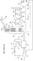
- a feed stream 100 which is preferably natural gas
- a pre-treatment section 90 to remove water, acid gases such as CO 2 and H 2 S, and other contaminants such as mercury, resulting in a pre-treated feed stream 101.
- the pre-treated feed stream 101 which is essentially water free, is pre-cooled in a pre-cooling system 118 to produce a precooled natural gas stream 105, and is further cooled, liquefied, and/or sub-cooled in an MCHE 108 to produce LNG stream 106.
- the LNG stream 106 is typically let down in pressure by passing it through a valve or a turbine (not shown) and is then sent to LNG storage tank 109. Any flash vapor produced during the pressure letdown and/or boil-off in the tank is represented by stream 107, which may be used as fuel in the plant, recycled to feed, or vented.
- the pre-treated feed stream 101 is pre-cooled to a temperature below 10 degrees Celsius, preferably below about 0 degrees Celsius, and more preferably about -30 degrees Celsius.
- the pre-cooled natural gas stream 105 is liquefied to a temperature between about -150 degrees Celsius and about -70 degrees Celsius, preferably between about -145 degrees Celsius and about -100 degrees Celsius, and subsequently sub-cooled to a temperature between about -170 degrees Celsius and about -120 degrees Celsius, preferably between about -170 degrees Celsius and about -140 degrees Celsius.
- MCHE 108 shown in FIG. 1 is a coil wound heat exchanger with three bundles. However, any number of bundles and any exchanger type may be utilized.
- water concentration is preferably not more than 1.0 ppm and, more preferably between 0.1 ppm and 0.5 ppm.
- the pre-cooling refrigerant used in the C3MR process is propane.
- propane refrigerant 110 is warmed against the pre-treated feed stream 101 to produce a warm low pressure propane stream 114.
- the warm low pressure propane stream 114 is compressed in one or more propane compressors 116 that may comprise four compression stages.
- Three side streams 111, 112, and 113 at intermediate pressure levels enter the propane compressors 116 at the suction side of the final, third, and second stages of the propane compressor 116 respectively.
- the compressed propane stream 115 is condensed in condenser 117 to produce a cold high pressure stream that is then let down in pressure (let down valve not shown) to produce the propane refrigerant 110 that provides the cooling duty required to cool pre-treated feed stream 101 in pre-cooling system 118.
- the propane liquid evaporates as it cools stream 101 to produce low pressure propane vapor stream 114.
- the condenser 117 typically exchanges heat against an ambient fluid such as air or water.
- any number of compression stages may be employed. It should be understood that when multiple compression stages are described or claimed, such multiple compression stages could comprise a single multi-stage compressor, multiple compressors, or a combination thereof.
- the compressors could be in a single casing or multiple casings.
- the process of compressing the propane refrigerant is generally referred to herein as the propane compression sequence.
- the propane compression sequence is described in greater detail in U.S. Patent Application Serial No. 14/870,557 , published as U.S. Patent Application Pub. No. 2017/0089637 A1 , the disclosure of which is incorporated by reference herein in its entirety.
- At least a portion of, and preferably all of the refrigeration is provided by vaporizing at least a portion of refrigerant streams after pressure reduction across valves or turbines.
- a low pressure gaseous MR stream 130 is withdrawn from the warm end of the shell side of the MCHE 108, sent through a low-pressure suction drum 150 to prevent any entrained droplets from entering the compressor 151 and the vapor stream 131 is compressed in a low pressure (LP) compressor 151 to produce medium pressure MR stream 132.
- the low pressure gaseous MR stream 130 is typically withdrawn at a temperature at or near propane pre-cooling temperature and preferably about -30 degrees Celsius and at a pressure of less than 10 bara (145 psia).
- the medium pressure MR stream 132 is cooled in a low-pressure aftercooler 152 to produce a cooled medium pressure MR stream 133 from which any entrained droplets may be optionally removed in a medium pressure suction drum 153 to produce medium pressure vapor stream 134 that is further compressed in medium pressure (MP) compressor 154.
- the resulting high-pressure MR stream 135 is cooled in a medium pressure aftercooler 155 to produce a cooled high pressure MR stream 136.
- the cooled high-pressure MR stream 136 is optionally sent to a high-pressure suction drum 156 to remove any entrained droplets.
- the resulting high-pressure vapor stream 137 is further compressed in a high pressure (HP) compressor 157 to produce high-high pressure MR stream 138 that is cooled in high pressure aftercooler 158 to produce a cooled high-high pressure MR stream 139.
- Cooled high-high pressure MR stream 139 is then cooled against evaporating propane in pre-cooling system 118 to produce a two-phase MR stream 140.
- Two-phase MR stream 140 is then sent to a vapor-liquid separator 159 from which an MRL stream 141 and an MRV stream 143 are obtained, which are sent back to MCHE 108 to be further cooled.
- the liquid stream leaving the phase separator is referred to in the industry as MRL and the vapor stream leaving the phase separator is referred to in the industry as MRV, even after they are subsequently liquefied.
- the process of compressing and cooling the MR after it is withdrawn from the bottom of the MCHE 108, then returned to the tube side of the MCHE 108 as multiple streams, is generally referred to herein as the MR compression sequence.
- Both the MRL stream 141 and MRV stream 143 are cooled, in two separate circuits of the MCHE 108.
- the MRL stream 141 is subcooled in the first two bundles of the MCHE 108, resulting in a cold stream that is let down in pressure to produce a cold two-phase stream 142 that is sent back to the shell-side of MCHE 108 to provide refrigeration required in the first two bundles of the MCHE.
- the MRV stream 143 is cooled, liquefied and subcooled in the first, second, and third bundles of MCHE 108, reduced in pressure across the cold high pressure letdown valve, and introduced to the MCHE 108 as stream 144 to provide refrigeration in the sub-cooling, liquefaction, and cooling steps.
- MCHE 108 can be any exchanger suitable for natural gas liquefaction such as a coil wound heat exchanger, plate and fin heat exchanger or a shell and tube heat exchanger.
- Coil wound heat exchangers are the state of art exchangers for natural gas liquefaction and include at least one tube bundle comprising a plurality of spiral wound tubes for flowing process and warm refrigerant streams and a shell space for flowing a cold refrigerant stream.
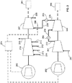
- FIG. 2 illustrates a first exemplary embodiment.
- elements shared with the system of FIG. 1 are represented by reference numerals increased by factors of 100.
- the propane compressors 116 in FIG. 1 correspond to the propane compressors 216 in FIG. 2 .
- some features of this embodiment that are shared with the second embodiment are numbered in FIG. 2 , but are not repeated in the specification. If a reference numeral is provided in this embodiment and not discussed in the specification, it should be understood to be identical to the corresponding element of the system shown in FIG. 1 . These same principles apply to each of the subsequent exemplary embodiments.
- FIG. 2 illustrates a SplitMR® natural gas liquefication system, which includes the elements of the system of FIG. 1 , but differs in how the compressors of the C3MR process and the MR process are driven.
- the system of FIG. 2 includes a first gas turbine 260 that mechanically drives the propane compressor 216 and the HP MR compressor 257 (which has the highest outlet pressure of all of the MR compressors 251, 254, 257).
- the system 200 also includes a second gas turbine 262 that mechanically drives the LP MR compressor 251 and the MP MR compressor 254.
- these compression strings could each include a helper/starter motor 264, 266, respectively.
- the power requirements of the three MR compression stages i.e., the LP, MP, and HP MR compressors 251, 254, and 257) and the propane compressor 216 are each set so that both gas turbines 260, 262 operate near capacity when overall production rate of the system 200 is operated near capacity.
- the power requirements for the propane compressor 216 increase, while the power available from the first gas turbine 260 deceases. In such circumstances, the discharge pressure of the propane compressor 216 must increase so that the propane therein can condense in the condenser. This increase in head (i.e., the work or energy in foot-pounds required to polytropically compress and transfer one pound of a given gas from one pressure level to another) requires the propane compressor 216 to use a larger portion of the power available from the first gas turbine 260 as compared to the design conditions.
- the split MR liquefication system is configured to adjust the characteristics of the HP MR compressor 257 to require less power in warmer ambient temperatures and more power in colder ambient temperatures compared to the design temperature. Such adjustments allow for shifting the balance of power between the propane compressor 216 and the HP MR compressor 257.
- the SplitMR® liquefication system shown in FIG. 2 incorporates a suction throttle valve 268 connected between the HP MR compressor 257 and the cooled HP MR stream 236 received from the MP aftercooler 255 connected to the MP MR compressor 254.
- the opening of a suction throttle valve 268 can be adjusted to change the density of the fluid and suction pressure of the fluid entering the HP MR compressor 257, thereby changing the amount of power the HP MR compressor 257 needs to perform efficiently.
- the suction throttle valve 268 When ambient temperature is higher than the design temperature for the MR liquefaction system, the suction throttle valve 268 is adjusted to a more closed position. This adjustment allows more power from the first gas turbine 260 to be devoted to the propane compressor 216, allowing for a greater circulation of propane flow. Increasing propane flow also allows for an increase in overall MR flow, resulting in a more efficient use of power from both the first and second gas turbines 260, 262. Overall, by regulating the density of cooled HP MR fluid via the suction throttle valve 268, more total available power from both the first and second gas turbines 260, 262 can be used to circulate more refrigerant, resulting in higher, more efficient LNG production.
- the power requirements for the propane compressor 216 decrease, while the power available from the first gas turbine 260 increases.
- the suction throttle valve 268 can be adjusted to a more open position. This has the benefit of shifting more power to the HP MR compressor 257, allowing the C3MR process to which the split MR liquefication system 200 is connected to increase LNG production at ambient temperatures colder than design.
- the term “power requirement differential” between the drivers 260, 262 is larger than at the design ambient conditions. This typically means that one of the drivers 260, 262 is operating at a "power ratio” that is close to 1.0 but the other driver is not.
- the term “power ratio” means the ratio of the power being delivered by the driver over the maximum available power to that driver.
- the term “power differential” is the difference between power ratio of the first driver and the power ratio of the second driver.
- the position of the suction throttle valve 268 and the power state of the turbines 260, 262 are monitored and controlled by a controller 274.
- the controller 274 includes the capability to measure (or otherwise determine) the ambient temperature and available power on the gas turbine drivers and is programmed to automatically adjust the position of the suction throttle valve 268 and the power state of the turbines 260, 262 based on ambient temperature.
- the controller 274 is not shown in FIGS. 3 or 7 but could be used in connection with either of the exemplary embodiments depicted therein.
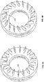
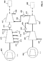
- the split MR liquefication system includes a set of adjustable inlet guide vanes 370 on the inlet of the HP MR compressor 357 that receives the cooled HP MR stream 336. At temperatures warmer than design, the inlet guide vanes 370 can be adjusted to impart less dynamic head per volumetric flow by the HP MR compressor 357, as illustrated in FIG.
- HP MR compressor 357 imparts less dynamic head per inlet volumetric flow from the cooled HP MR stream 336, thus lowering the power requirement for the HP MR compressor 357 and increasing the power available for the propane compressor 316.
- the inlet guide vanes 370 on the HP MR compressor 357 can be opened, as illustrated in FIG. 4A , to impart more dynamic head per volumetric flow and increase the power consumption of the HP MR compressor 357.
- the inlet guide vanes 370 shown in FIG. 3 can be beneficial over the suction throttle valve 268 shown in FIG. 2 in that the inlet guide vanes 370 avoid the losses associated with throttling the suction of the HP MR compressor 257.
- adjustable diffuser vanes could be used to adjust the power requirement of the HP MR compressor 357 instead of adjustable inlet guide vanes 370. Instead of being located at the inlet (suction side) of a compression stage, diffuser vanes are located on the outlet side. This method will change the dynamic head and flow characteristics of the compressor in a way that is different than the inlet guide vanes.
- FIG. 5 shows an exemplary head/flow chart for a compressor stage.
- the capacity of the compressor increases and delivers more head per volumetric flow, which in turn will absorb more power from the driver.
- closing the inlet guide vanes reduces the capacity of the compressor and delivers less head per volumetric flow, which in turn will absorb less power from the driver.
- FIG. 6 illustrates a third embodiment of a split MR liquefication system that is configured to change the characteristics of the HP MR compressor 457 to shift power to/from the propane compressor 416.
- the split MR liquefication system modulates the speed of the HP MR compressor 457 using a variable speed gearbox 472 installed between the propane compressor 416 and the HP MR compressor 457.
- the variable speed gearbox 472 enables the HP MR compressor 457 to operate at an optimal speed that may be higher or lower than the optimal speed of the propane compressor 416.
- the variable speed gearbox 472 is configured to make adjustments to the speed of operation for the HP MR compressor in accordance with changes to the ambient temperature of the split MR liquefication system 400.
- the gas turbines i.e., first and second gas turbines 260 and 262, 360 and 362, and 460 and 462
- the gas turbines may be substituted for steam turbines, aero-derivative turbines, or electric motors. All other such modifications are intended to be considered within the scope of the present invention. It is intended that the present invention only be limited by the terms of the appended claims.
Landscapes
- Engineering & Computer Science (AREA)
- Physics & Mathematics (AREA)
- Mechanical Engineering (AREA)
- Thermal Sciences (AREA)
- General Engineering & Computer Science (AREA)
- Chemical & Material Sciences (AREA)
- Chemical Kinetics & Catalysis (AREA)
- General Chemical & Material Sciences (AREA)
- Oil, Petroleum & Natural Gas (AREA)
- Separation By Low-Temperature Treatments (AREA)
Applications Claiming Priority (1)
| Application Number | Priority Date | Filing Date | Title |
|---|---|---|---|
| US16/053,196 US10935312B2 (en) | 2018-08-02 | 2018-08-02 | Balancing power in split mixed refrigerant liquefaction system |
Publications (3)
| Publication Number | Publication Date |
|---|---|
| EP3604993A2 true EP3604993A2 (de) | 2020-02-05 |
| EP3604993A3 EP3604993A3 (de) | 2020-04-08 |
| EP3604993B1 EP3604993B1 (de) | 2026-04-29 |
Family
ID=67514449
Family Applications (1)
| Application Number | Title | Priority Date | Filing Date |
|---|---|---|---|
| EP19189482.3A Active EP3604993B1 (de) | 2018-08-02 | 2019-07-31 | Ausgleichen der leistung in einem geteilten gemischten kältemittelverflüssigungssystem |
Country Status (8)
| Country | Link |
|---|---|
| US (1) | US10935312B2 (de) |
| EP (1) | EP3604993B1 (de) |
| JP (1) | JP6889759B2 (de) |
| KR (1) | KR102282314B1 (de) |
| CN (2) | CN211424733U (de) |
| AU (1) | AU2019208279B2 (de) |
| CA (1) | CA3050798C (de) |
| RU (1) | RU2766164C2 (de) |
Families Citing this family (3)
| Publication number | Priority date | Publication date | Assignee | Title |
|---|---|---|---|---|
| US10935312B2 (en) * | 2018-08-02 | 2021-03-02 | Air Products And Chemicals, Inc. | Balancing power in split mixed refrigerant liquefaction system |
| CN115031490B (zh) * | 2022-06-18 | 2023-03-24 | 华海(北京)科技股份有限公司 | 节能型液化天然气冷能空分系统 |
| RU2795716C1 (ru) * | 2022-11-02 | 2023-05-11 | Олеся Игоревна Гасанова | Способ сжижения природного газа |
Citations (2)
| Publication number | Priority date | Publication date | Assignee | Title |
|---|---|---|---|---|
| US3763658A (en) | 1970-01-12 | 1973-10-09 | Air Prod & Chem | Combined cascade and multicomponent refrigeration system and method |
| US20170089637A1 (en) | 2015-09-30 | 2017-03-30 | Air Products And Chemicals, Inc. | Parallel Compression in LNG Plants Using a Positive Displacement Compressor |
Family Cites Families (15)
| Publication number | Priority date | Publication date | Assignee | Title |
|---|---|---|---|---|
| GB1208196A (en) * | 1967-12-20 | 1970-10-07 | Messer Griesheim Gmbh | Process for the liquifaction of nitrogen-containing natural gas |
| US5791160A (en) | 1997-07-24 | 1998-08-11 | Air Products And Chemicals, Inc. | Method and apparatus for regulatory control of production and temperature in a mixed refrigerant liquefied natural gas facility |
| MY128820A (en) | 2000-04-25 | 2007-02-28 | Shell Int Research | Controlling the production of a liquefied natural gas product stream |
| DE102004023814A1 (de) | 2004-05-13 | 2005-12-01 | Linde Ag | Verfahren und Vorrichtung zum Verflüssigen eines Kohlenwasserstoff-reichen Stromes |
| US7712299B2 (en) * | 2006-09-05 | 2010-05-11 | Conocophillips Company | Anti-bogdown control system for turbine/compressor systems |
| WO2008139528A1 (ja) | 2007-04-27 | 2008-11-20 | Hitachi, Ltd. | 冷却サイクル系統、天然ガス液化設備、冷却サイクル系統の運転方法及び改造方法 |
| AU2009228000B2 (en) * | 2008-09-19 | 2013-03-07 | Woodside Energy Limited | Mixed refrigerant compression circuit |
| FR2943125B1 (fr) * | 2009-03-13 | 2015-12-18 | Total Sa | Procede de liquefaction de gaz naturel a cycle combine |
| US8210828B2 (en) * | 2010-03-30 | 2012-07-03 | Ford Global Technologies, Llc | Methods and systems for assisted direct start control |
| EP2604960A1 (de) | 2011-12-15 | 2013-06-19 | Shell Internationale Research Maatschappij B.V. | Verfahren zum Betreiben eines Kompressors und System und Verfahren zum Herstellen eines flüssigen Kohlenwasserstoffstroms |
| RU2570795C1 (ru) * | 2014-07-15 | 2015-12-10 | Игорь Анатольевич Мнушкин | Газоперерабатывающий и газохимический комплекс |
| US10359228B2 (en) * | 2016-05-20 | 2019-07-23 | Air Products And Chemicals, Inc. | Liquefaction method and system |
| ITUA20164168A1 (it) | 2016-06-07 | 2017-12-07 | Nuovo Pignone Tecnologie Srl | Treno di compressione con due compressori centrifughi e impianto lng con due compressori centrifughi |
| IT201600109378A1 (it) * | 2016-10-28 | 2018-04-28 | Nuovo Pignone Tecnologie Srl | Sistema di liquefazione di gas naturale comprendente un turbocompressore con moltiplicatore integrato |
| US10935312B2 (en) * | 2018-08-02 | 2021-03-02 | Air Products And Chemicals, Inc. | Balancing power in split mixed refrigerant liquefaction system |
-
2018
- 2018-08-02 US US16/053,196 patent/US10935312B2/en active Active
-
2019
- 2019-07-25 JP JP2019136744A patent/JP6889759B2/ja active Active
- 2019-07-26 KR KR1020190091288A patent/KR102282314B1/ko active Active
- 2019-07-29 AU AU2019208279A patent/AU2019208279B2/en active Active
- 2019-07-30 CA CA3050798A patent/CA3050798C/en active Active
- 2019-07-31 EP EP19189482.3A patent/EP3604993B1/de active Active
- 2019-07-31 RU RU2019124185A patent/RU2766164C2/ru active
- 2019-08-02 CN CN201921243565.7U patent/CN211424733U/zh not_active Withdrawn - After Issue
- 2019-08-02 CN CN201910711555.XA patent/CN110793231B/zh active Active
Patent Citations (2)
| Publication number | Priority date | Publication date | Assignee | Title |
|---|---|---|---|---|
| US3763658A (en) | 1970-01-12 | 1973-10-09 | Air Prod & Chem | Combined cascade and multicomponent refrigeration system and method |
| US20170089637A1 (en) | 2015-09-30 | 2017-03-30 | Air Products And Chemicals, Inc. | Parallel Compression in LNG Plants Using a Positive Displacement Compressor |
Also Published As
| Publication number | Publication date |
|---|---|
| CA3050798C (en) | 2021-11-23 |
| JP6889759B2 (ja) | 2021-06-18 |
| KR102282314B1 (ko) | 2021-07-26 |
| US20200041203A1 (en) | 2020-02-06 |
| RU2766164C2 (ru) | 2022-02-08 |
| EP3604993B1 (de) | 2026-04-29 |
| JP2020020567A (ja) | 2020-02-06 |
| RU2019124185A3 (de) | 2021-12-09 |
| US10935312B2 (en) | 2021-03-02 |
| KR20200015387A (ko) | 2020-02-12 |
| CA3050798A1 (en) | 2020-02-02 |
| AU2019208279B2 (en) | 2021-09-09 |
| EP3604993A3 (de) | 2020-04-08 |
| CN211424733U (zh) | 2020-09-04 |
| CN110793231B (zh) | 2022-02-11 |
| CN110793231A (zh) | 2020-02-14 |
| RU2019124185A (ru) | 2021-02-01 |
| AU2019208279A1 (en) | 2020-02-20 |
Similar Documents
| Publication | Publication Date | Title |
|---|---|---|
| AU2019268173B2 (en) | Multiple pressure mixed refrigerant cooling process and system | |
| AU2020201573B2 (en) | Parallel compression in lng plants using a double flow compressor | |
| US10180282B2 (en) | Parallel compression in LNG plants using a positive displacement compressor | |
| US10866022B2 (en) | Method and system for cooling a hydrocarbon stream using a gas phase refrigerant | |
| US10753676B2 (en) | Multiple pressure mixed refrigerant cooling process | |
| EP3604993B1 (de) | Ausgleichen der leistung in einem geteilten gemischten kältemittelverflüssigungssystem | |
| AU2018233053B2 (en) | Multiple pressure mixed refrigerant cooling system |
Legal Events
| Date | Code | Title | Description |
|---|---|---|---|
| PUAI | Public reference made under article 153(3) epc to a published international application that has entered the european phase |
Free format text: ORIGINAL CODE: 0009012 |
|
| STAA | Information on the status of an ep patent application or granted ep patent |
Free format text: STATUS: THE APPLICATION HAS BEEN PUBLISHED |
|
| AK | Designated contracting states |
Kind code of ref document: A2 Designated state(s): AL AT BE BG CH CY CZ DE DK EE ES FI FR GB GR HR HU IE IS IT LI LT LU LV MC MK MT NL NO PL PT RO RS SE SI SK SM TR |
|
| AX | Request for extension of the european patent |
Extension state: BA ME |
|
| PUAL | Search report despatched |
Free format text: ORIGINAL CODE: 0009013 |
|
| AK | Designated contracting states |
Kind code of ref document: A3 Designated state(s): AL AT BE BG CH CY CZ DE DK EE ES FI FR GB GR HR HU IE IS IT LI LT LU LV MC MK MT NL NO PL PT RO RS SE SI SK SM TR |
|
| AX | Request for extension of the european patent |
Extension state: BA ME |
|
| RIC1 | Information provided on ipc code assigned before grant |
Ipc: F25J 1/02 20060101ALI20200304BHEP Ipc: F25J 1/00 20060101AFI20200304BHEP |
|
| RBV | Designated contracting states (corrected) |
Designated state(s): AL AT BE BG CH CY CZ DE DK EE ES FI FR GB GR HR HU IE IS IT LI LT LU LV MC MK MT NL NO PL PT RO RS SE SI SK SM TR |
|
| STAA | Information on the status of an ep patent application or granted ep patent |
Free format text: STATUS: REQUEST FOR EXAMINATION WAS MADE |
|
| 17P | Request for examination filed |
Effective date: 20201021 |
|
| STAA | Information on the status of an ep patent application or granted ep patent |
Free format text: STATUS: EXAMINATION IS IN PROGRESS |
|
| 17Q | First examination report despatched |
Effective date: 20221019 |
|
| RAP1 | Party data changed (applicant data changed or rights of an application transferred) |
Owner name: HERCULES PROJECT COMPANY LLC |
|
| RAP3 | Party data changed (applicant data changed or rights of an application transferred) |
Owner name: HONEYWELL LNG LLC |
|
| GRAP | Despatch of communication of intention to grant a patent |
Free format text: ORIGINAL CODE: EPIDOSNIGR1 |
|
| STAA | Information on the status of an ep patent application or granted ep patent |
Free format text: STATUS: GRANT OF PATENT IS INTENDED |
|
| INTG | Intention to grant announced |
Effective date: 20251215 |
|
| GRAS | Grant fee paid |
Free format text: ORIGINAL CODE: EPIDOSNIGR3 |
|
| GRAA | (expected) grant |
Free format text: ORIGINAL CODE: 0009210 |
|
| STAA | Information on the status of an ep patent application or granted ep patent |
Free format text: STATUS: THE PATENT HAS BEEN GRANTED |
|
| AK | Designated contracting states |
Kind code of ref document: B1 Designated state(s): AL AT BE BG CH CY CZ DE DK EE ES FI FR GB GR HR HU IE IS IT LI LT LU LV MC MK MT NL NO PL PT RO RS SE SI SK SM TR |
|
| REG | Reference to a national code |
Ref country code: CH Ref legal event code: F10 Free format text: ST27 STATUS EVENT CODE: U-0-0-F10-F00 (AS PROVIDED BY THE NATIONAL OFFICE) Effective date: 20260429 |