EP3604885B1 - Flüssigkeitsverwirbeler - Google Patents
Flüssigkeitsverwirbeler Download PDFInfo
- Publication number
- EP3604885B1 EP3604885B1 EP18187176.5A EP18187176A EP3604885B1 EP 3604885 B1 EP3604885 B1 EP 3604885B1 EP 18187176 A EP18187176 A EP 18187176A EP 3604885 B1 EP3604885 B1 EP 3604885B1
- Authority
- EP
- European Patent Office
- Prior art keywords
- joint
- port
- tube
- center
- axis
- Prior art date
- Legal status (The legal status is an assumption and is not a legal conclusion. Google has not performed a legal analysis and makes no representation as to the accuracy of the status listed.)
- Active
Links
Images






Classifications
-
- F—MECHANICAL ENGINEERING; LIGHTING; HEATING; WEAPONS; BLASTING
- F16—ENGINEERING ELEMENTS AND UNITS; GENERAL MEASURES FOR PRODUCING AND MAINTAINING EFFECTIVE FUNCTIONING OF MACHINES OR INSTALLATIONS; THERMAL INSULATION IN GENERAL
- F16L—PIPES; JOINTS OR FITTINGS FOR PIPES; SUPPORTS FOR PIPES, CABLES OR PROTECTIVE TUBING; MEANS FOR THERMAL INSULATION IN GENERAL
- F16L27/00—Adjustable joints; Joints allowing movement
- F16L27/08—Adjustable joints; Joints allowing movement allowing adjustment or movement only about the axis of one pipe
- F16L27/087—Joints with radial fluid passages
-
- F—MECHANICAL ENGINEERING; LIGHTING; HEATING; WEAPONS; BLASTING
- F16—ENGINEERING ELEMENTS AND UNITS; GENERAL MEASURES FOR PRODUCING AND MAINTAINING EFFECTIVE FUNCTIONING OF MACHINES OR INSTALLATIONS; THERMAL INSULATION IN GENERAL
- F16L—PIPES; JOINTS OR FITTINGS FOR PIPES; SUPPORTS FOR PIPES, CABLES OR PROTECTIVE TUBING; MEANS FOR THERMAL INSULATION IN GENERAL
- F16L3/00—Supports for pipes, cables or protective tubing, e.g. hangers, holders, clamps, cleats, clips, brackets
- F16L3/01—Supports for pipes, cables or protective tubing, e.g. hangers, holders, clamps, cleats, clips, brackets for supporting or guiding the pipes, cables or protective tubing, between relatively movable points, e.g. movable channels
- F16L3/015—Supports for pipes, cables or protective tubing, e.g. hangers, holders, clamps, cleats, clips, brackets for supporting or guiding the pipes, cables or protective tubing, between relatively movable points, e.g. movable channels using articulated- or supple-guiding elements
-
- B—PERFORMING OPERATIONS; TRANSPORTING
- B64—AIRCRAFT; AVIATION; COSMONAUTICS
- B64C—AEROPLANES; HELICOPTERS
- B64C29/00—Aircraft capable of landing or taking-off vertically, e.g. vertical take-off and landing [VTOL] aircraft
- B64C29/0008—Aircraft capable of landing or taking-off vertically, e.g. vertical take-off and landing [VTOL] aircraft having its flight directional axis horizontal when grounded
- B64C29/0016—Aircraft capable of landing or taking-off vertically, e.g. vertical take-off and landing [VTOL] aircraft having its flight directional axis horizontal when grounded the lift during taking-off being created by free or ducted propellers or by blowers
- B64C29/0033—Aircraft capable of landing or taking-off vertically, e.g. vertical take-off and landing [VTOL] aircraft having its flight directional axis horizontal when grounded the lift during taking-off being created by free or ducted propellers or by blowers the propellers being tiltable relative to the fuselage
-
- F—MECHANICAL ENGINEERING; LIGHTING; HEATING; WEAPONS; BLASTING
- F01—MACHINES OR ENGINES IN GENERAL; ENGINE PLANTS IN GENERAL; STEAM ENGINES
- F01M—LUBRICATING OF MACHINES OR ENGINES IN GENERAL; LUBRICATING INTERNAL COMBUSTION ENGINES; CRANKCASE VENTILATING
- F01M11/00—Component parts, details or accessories, not provided for in, or of interest apart from, groups F01M1/00 - F01M9/00
- F01M11/06—Means for keeping lubricant level constant or for accommodating movement or position of machines or engines
- F01M11/062—Accommodating movement or position of machines or engines, e.g. dry sumps
- F01M11/064—Movement
-
- F—MECHANICAL ENGINEERING; LIGHTING; HEATING; WEAPONS; BLASTING
- F16—ENGINEERING ELEMENTS AND UNITS; GENERAL MEASURES FOR PRODUCING AND MAINTAINING EFFECTIVE FUNCTIONING OF MACHINES OR INSTALLATIONS; THERMAL INSULATION IN GENERAL
- F16L—PIPES; JOINTS OR FITTINGS FOR PIPES; SUPPORTS FOR PIPES, CABLES OR PROTECTIVE TUBING; MEANS FOR THERMAL INSULATION IN GENERAL
- F16L27/00—Adjustable joints; Joints allowing movement
- F16L27/08—Adjustable joints; Joints allowing movement allowing adjustment or movement only about the axis of one pipe
- F16L27/0849—Adjustable joints; Joints allowing movement allowing adjustment or movement only about the axis of one pipe the fluid being turned through an angle when passing from one joint element to another
-
- F—MECHANICAL ENGINEERING; LIGHTING; HEATING; WEAPONS; BLASTING
- F16—ENGINEERING ELEMENTS AND UNITS; GENERAL MEASURES FOR PRODUCING AND MAINTAINING EFFECTIVE FUNCTIONING OF MACHINES OR INSTALLATIONS; THERMAL INSULATION IN GENERAL
- F16L—PIPES; JOINTS OR FITTINGS FOR PIPES; SUPPORTS FOR PIPES, CABLES OR PROTECTIVE TUBING; MEANS FOR THERMAL INSULATION IN GENERAL
- F16L39/00—Joints or fittings for double-walled or multi-channel pipes or pipe assemblies
- F16L39/04—Joints or fittings for double-walled or multi-channel pipes or pipe assemblies allowing adjustment or movement
-
- F—MECHANICAL ENGINEERING; LIGHTING; HEATING; WEAPONS; BLASTING
- F16—ENGINEERING ELEMENTS AND UNITS; GENERAL MEASURES FOR PRODUCING AND MAINTAINING EFFECTIVE FUNCTIONING OF MACHINES OR INSTALLATIONS; THERMAL INSULATION IN GENERAL
- F16L—PIPES; JOINTS OR FITTINGS FOR PIPES; SUPPORTS FOR PIPES, CABLES OR PROTECTIVE TUBING; MEANS FOR THERMAL INSULATION IN GENERAL
- F16L39/00—Joints or fittings for double-walled or multi-channel pipes or pipe assemblies
- F16L39/06—Joints or fittings for double-walled or multi-channel pipes or pipe assemblies of the multiline swivel type, e.g. comprising a plurality of axially mounted modules
-
- B—PERFORMING OPERATIONS; TRANSPORTING
- B60—VEHICLES IN GENERAL
- B60R—VEHICLES, VEHICLE FITTINGS, OR VEHICLE PARTS, NOT OTHERWISE PROVIDED FOR
- B60R16/00—Electric or fluid circuits specially adapted for vehicles and not otherwise provided for; Arrangement of elements of electric or fluid circuits specially adapted for vehicles and not otherwise provided for
- B60R16/08—Electric or fluid circuits specially adapted for vehicles and not otherwise provided for; Arrangement of elements of electric or fluid circuits specially adapted for vehicles and not otherwise provided for fluid
-
- B—PERFORMING OPERATIONS; TRANSPORTING
- B64—AIRCRAFT; AVIATION; COSMONAUTICS
- B64C—AEROPLANES; HELICOPTERS
- B64C27/00—Rotorcraft; Rotors peculiar thereto
- B64C27/52—Tilting of rotor bodily relative to fuselage
-
- F—MECHANICAL ENGINEERING; LIGHTING; HEATING; WEAPONS; BLASTING
- F16—ENGINEERING ELEMENTS AND UNITS; GENERAL MEASURES FOR PRODUCING AND MAINTAINING EFFECTIVE FUNCTIONING OF MACHINES OR INSTALLATIONS; THERMAL INSULATION IN GENERAL
- F16L—PIPES; JOINTS OR FITTINGS FOR PIPES; SUPPORTS FOR PIPES, CABLES OR PROTECTIVE TUBING; MEANS FOR THERMAL INSULATION IN GENERAL
- F16L27/00—Adjustable joints; Joints allowing movement
- F16L27/08—Adjustable joints; Joints allowing movement allowing adjustment or movement only about the axis of one pipe
- F16L27/0804—Adjustable joints; Joints allowing movement allowing adjustment or movement only about the axis of one pipe the fluid passing axially from one joint element to another
- F16L27/0837—Adjustable joints; Joints allowing movement allowing adjustment or movement only about the axis of one pipe the fluid passing axially from one joint element to another the joint elements being bends
- F16L27/0845—Adjustable joints; Joints allowing movement allowing adjustment or movement only about the axis of one pipe the fluid passing axially from one joint element to another the joint elements being bends forming an angle of 90 degrees
Definitions
- Tiltrotor aircraft include at least one pair of proprotors that rotate between a vertically-oriented helicopter position and a horizontally-oriented airplane position.
- US 2,659,615 (A ) discloses a swivel or swing joint arranged to provide dual hydraulic circuits which provide fluid to double acting or dual hydraulic mechanisms movable rotationally and/or translationally relative to the source of hydraulic fluid and/or controls therefor.
- This disclosure divulges a low-profile fluid swivel for transmitting fluid across a hinge axis. While the fluid swivel is shown, and discussed for use, with rotatable proprotors of a tiltrotor aircraft, it should be understood that the fluid swivel could be used anywhere it is required to transmit fluids across a hinge.
- the fluid swivel includes at least two separate fluid paths, usually a delivery path and a return path.
- the fluid swivel includes a first end configured to be coupled to a first pair of lines on a first side of the hinge, a second end configured to be coupled to a second pair of lines on a second side of the hinge, a joint between the first end and the second end, a first pair of tubes extending from the first end to the joint, and a second pair of tubes extending from the joint to the second end.
- the fluid swivel has a low profile because the first and second tubes lie in a plane that is substantially perpendicular to an axis of rotation of the joint.
- utilizing a design disclosed herein would enable manufacture of a fluid swivel with 1.6 cm (five-eighths of an inch) internal diameter fluid tubes to have a total width of approximately 7.6 cm (three inches), or 2.5 cm (linch) internal diameter fluid tubes to have a total width of approximately 11.4 cm (four and a half inches).
- Tiltrotor aircraft 100 includes a fuselage 102, a landing gear 104, a tail member 106, a wing 108, a propulsion system 110, and a propulsion system 112.
- Each propulsion system 110 and 112 includes an engine and a rotatable proprotor 114 and 116, respectively.
- Each rotatable proprotor 114 and 116 has a plurality of rotor blades 118 and 120, respectively, associated therewith.
- the position of proprotors 114 and 116, as well as the pitch of rotor blades 118 and 120, can be selectively controlled to control direction, thrust, and lift of tiltrotor aircraft 100.
- FIG. 1 illustrates tiltrotor aircraft 100 in a helicopter mode, in which proprotors 114 and 116 are positioned substantially vertical to provide a lifting thrust.
- FIG. 2 illustrates tiltrotor aircraft 100 in an airplane mode, in which proprotors 114 and 116 are positioned substantially horizontal to provide a forward thrust in which a lifting force is supplied by wing 108. It should be appreciated that tiltrotor aircraft 100 can be operated such that proprotors 114 and 116 are selectively positioned between airplane mode and helicopter mode, which can be referred to as a conversion mode.
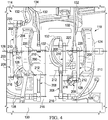
- FIGS. 3 and 4 illustrate a portion of propulsion system 110 with a cowling 122 removed to show a hinge 124 with a hinge axis 126 about which proprotor 114 rotates, shown with proprotor 114 in airplane mode. Also shown are a plurality of fluid swivels 200 coupled between first pairs of fluid lines 128 on a first side 130 of hinge 124 and second pairs of fluid lines 132 on a second side 134 of hinge 124.
- first side 130 is fixed relative to wing 108 and second side 134 rotates about hinge axis 126 relative to first side 130.
- first pairs of fluid lines 128 are fixed relative to first side 130 and second pairs of fluid lines 132 are fixed relative to second side 134.
- plurality of fluid swivels 200 are provided to circulate fluids, such as oil, coolant, or hydraulic fluid, across hinge 124 from first side 130 to second side 134 and back.
- Each fluid swivel 200 includes a first fluid path 202 and a second fluid path 204 that extend across hinge 124 to connect first pair of fluid lines 128 with second pair of fluid lines 132, allowing the fluid to pass through fluid swivel 200.
- Each fluid swivel 200 includes a center joint 206 along first and second fluid paths 202 and 204 that divides first and second fluid paths 202 and 204 into a first portion 208 and a second portion 210, such that first portion 208 and second portion 210 rotate relative to each other about a center-joint axis 212.
- each fluid swivel 200 includes a first-end joint 214 that enables a section of first portion 208 to rotate relative to first pair of fluid lines 128 about a first-end-joint axis 216 and a second-end joint 218 that enables a section of second portion 210 to rotate relative to second pair of fluid lines 132 about a second-end-joint axis 220.
- first side 130, the section of first portion 208 between center joint 206 and first-end joint 214, the section of second portion 210 between center joint 206 and second-end joint 218, and second side 134 operate as the four bars of a four-bar linkage when proprotor 114 rotates between airplane mode and helicopter mode.
- fluid swivels 200 have a low lateral profile because the fluid paths are stacked vertically relative to horizontal axes 126, 212, 216, and 220. That is, with respect to each fluid swivel 200, a majority of a length of first portion 208 of first fluid path 202 and second fluid path 204 lie in a first plane that is substantially perpendicular to center-joint axis 212 and a majority of a length of second portion 210 of the first fluid path 202 and the second fluid path 204 lie in a second plane that is substantially perpendicular to center-joint axis 212.
- first portion 208 to have some flexibility transverse to the first plane, thereby permitting some relative, out of the first plane, movement between center joint 206 and first pair of fluid lines 128.
- second portion 210 could be configured to have some flexibility transverse to the second plane, thereby permitting some relative, out of the second plane, movement between center joint 206 and second pair of fluid lines 132.
- FIGS. 5-7 show fluid swivel 200 in more detail.
- Fluid swivel 200 includes a housing 222 that includes a first passageway 224 configured to be coupled to one of first pair of fluid lines 128.
- Housing 222 also includes a second passageway 226 configured to be coupled to the other of first pair of fluid lines 128.
- First passageway 224 and second passageway 226 both enter and exit housing 222 substantially parallel to first-end-joint axis 216.
- Housing 222 is rotatably coupled to first-end joint 214 so that housing 222 and first-end joint 214 rotate relative to each other about first-end-joint axis 216.
- First-end joint 214 includes a first passage 228 in communication with first passageway 224 of housing 222 and a second passage 230 in communication with second passageway 226 of housing 222.
- First passage 228 and second passage 230 enter first-end joint 214 parallel to first-end-joint axis 216 and exit first-end joint 214 perpendicular to first-end-joint axis 216.
- a first tube 232 is coupled to first passage 228 and a second tube 234 is coupled to second passage 230.
- First tube 232 is coupled to a first port 236 of center joint 206 and second tube 234 is coupled to a second port 238 of center joint 206.
- first port 236 has a first-port axis 240 and second port 238 has a second-port axis 242, wherein both first-port axis 240 and second-port axis 242 are substantially perpendicular to center-joint axis 212.
- First port 236 and second port 238 are stacked such that first-port axis 240 and second-port axis 242 lie in a first plane that is substantially perpendicular to center-joint axis 212.
- First port 236 is in communication with a third port 244 that has a third-port axis 246 that is coaxial with center-joint axis 212.
- Second port 238 is in communication with a fourth port 248 that has a fourth-port axis 250 that is coaxial with center-joint axis 212.
- a rigid unitary member 252 is rotatably coupled to center joint 206.
- Member 252 includes a third tube and a fourth tube that extend therethrough (not shown).
- the third tube is in communication with third port 244 and the fourth tube is in communication with fourth port 248. While not shown, it should be understood that because the third tube is in communication with first tube 232, through first port 236 and third port 244, the third tube should have approximately the same cross-sectional area as first tube 232. Similarly, because the fourth tube is in communication with second tube 234, through second port 238 and fourth port 248, the fourth tube should have approximately the same cross-sectional area as second tube 234. It should be noted that because first tube 232 and second tube 234 may be carrying different volumes of fluids or fluids at drastically different pressures, the cross-sectional areas thereof may be different, depending on the particular application of fluid swivel 200.
- center-joint axis 212, third-port axis 246, and fourth-port axis 250 are shown as coaxial, they need not be.
- fourth port 248 may be radially offset from center-joint axis 212.
- a perimeter of fourth port 248 surrounds center-joint axis 212.
- third port 244 surround the entire perimeter of fourth port 248, as shown in FIG. 7 . Because center joint 206 rotates relative to member 252, third port 244 need only extend as far around the perimeter of fourth port 248 as is required to accommodate the intended degree of rotation for the particular application. For example, if the application requires ninety degrees of rotation, then third port 244 should surround at least one quarter of the perimeter of fourth port 248.
- Second-end joint 218 is rotatably coupled to member 252 about second-end-joint axis 220.
- Second-end joint 218 includes a first duct 254 in communication with the third tube of member 252 and a second duct 256 in communication with the fourth tube of member 252.
- First duct 254 and second duct 256 enter second-end joint 218 parallel to second-end-joint axis 220 and exit second-end joint 218 perpendicular to second-end-joint axis 220.
- first duct 254 is configured to be coupled to one of second pair of fluid lines 132 and second duct 256 is configured to be coupled to the other of second pair of fluid lines 132.
- first fluid path 202 conveys fluid from one of first pair of fluid lines 128 on first side 130 of hinge 124 to one of second pair of fluid lines 132 on second side 134 of hinge 124.
- First fluid path 202 includes: first passageway 224 of housing 222, first passage 228 of first-end joint 214, first tube 232, first port 236 and third port 244 of center joint 206, the third tube of member 252, and first duct 254 of second-end joint 218.
- Second fluid path 204 conveys fluid from the other of first pair of fluid lines 128 on first side 130 of hinge 124 to the other of second pair of fluid lines 132 on second side of hinge 124.
- Second fluid path 204 includes: second passageway 226 of housing 222, second passage 230 of first-end joint 214, second tube 234, second port 238 and fourth port 248 of center joint 206, the fourth tube of member 252, and second duct 256 of second-end joint 218.
- first tube 232 and second tube 234 are made of a semi-flexible hosing to permit flexing, and a first support member 258 and a second support member 260 are coupled between first-end joint 214 and center joint 206.
- First support member 258 and second support member 260 are stiff perpendicular to first-end-joint axis 216 and center-joint axis 212 so that they carry the load and act as the driving link between first-end joint 214 and center joint 206 during movement of fluid swivel 200, but the thin material of support members 258 and 260 parallel to first-end-joint axis 216 and center-joint axis 212 allows for some relative movement between first-end joint 214 and center joint 206.
- first-end joint 214 and second-end joint 218 are not shown individually, as center joint 206 is in FIG. 7 , it should be understood that the structure of first-end joint 214 and second-end joint 218 are substantially similar to that of center joint 206.
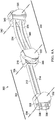
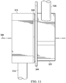
- FIGS. 8A-11 show a fluid swivel 300.
- Fluid swivel 300 includes a first link 302 rotatably coupled to a second link 304 about a center-joint axis 306.
- First link 302 includes a first-end member 308, a center member 310, and a first tube 312 and a second tube 314 coupled between first-end member 308 and center member 310.
- First tube 312 and second tube 314 are substantially parallel to each other along a majority of their lengths. As shown, the length of first tube 312 and center-joint axis 306 are skew. That is, first tube 312 is offset from center-joint axis 306.
- First-end member 308 includes a first passage and a second passage extending therethrough (not shown), wherein the first passage and the second passage each have an entrance and an exit that are substantially perpendicular to each other.
- center member 310 includes a first duct 316 and a second duct 318 extending therethrough, wherein first duct 316 and second duct 318 each have an entrance and an exit that are substantially perpendicular to each other. Accordingly, the first passage of first-end member 308, first tube 312, and first duct 316 are all in communication with each other, and the second passage of first-end member 308, second tube 314, and second duct 318 are all in communication with each other.
- Second link 304 includes a second-end member 320, a central member 322, and a third tube 324 and a fourth tube 326 coupled between second-end member 320 and central member 322.
- Third tube 324 and fourth tube 326 are substantially parallel to each other along a majority of their lengths. As shown, the length of third tube 324 and center-joint axis 306 are skew. That is, third tube 324 is offset from center-joint axis 306. Conversely, as shown, the length of fourth tube 326 would intersect center-joint axis 306. However, it should be understood that fourth tube 326 may be offset from center-joint axis 306 as well.
- Second-end member 320 includes a first passageway and a second passageway extending therethrough (not shown), wherein the first passageway and the second passageway each have an entrance and an exit that are substantially perpendicular to each other.
- central member 322 includes a first tunnel 328 and a second tunnel 330 extending therethrough, wherein first tunnel 328 and second tunnel 330 each have an entrance and an exit that are substantially perpendicular to each other. Accordingly, the first passageway of second-end member 320, third tube 324, and first tunnel 328 are all in communication with each other, and the second passageway of second-end member 320, fourth tube 326, and second tunnel 330 are all in communication with each other.
- Fluid swivel 300 further includes a first-end housing 332 rotatably coupled to first-end member 308 about a first-end axis 334.
- First-end housing 332 includes a first conduit 336 and a second conduit 338 extending therethrough, wherein first conduit 336 and second conduit 338 each have an entrance and an exit that are substantially perpendicular to each other.
- First conduit 336 is coupled to the first passage of first-end member 308 and is configured to be coupled to one of first pair of fluid lines 128.
- Second conduit 338 is coupled to the second passage of first-end member 308 and is configured to be coupled to the other of first pair of fluid lines 128.
- Fluid swivel 300 further includes a second-end housing 340 rotatably coupled to second-end member 320 about a second-end axis 342.
- Second-end housing 340 includes a first route and a second route extending therethrough (not shown), wherein the first route and the second route each have an entrance and an exit that are substantially perpendicular to each other. Alternatively, the entrance and exit of the first and second routes may both be oriented parallel to second-end axis 342.
- the first route is coupled to the first passageway of second-end member 320 and is configured to be coupled to one of second pair of fluid lines 132.
- the second route is coupled to the second passageway of second-end member 320 and is configured to be coupled to the other of second pair of fluid lines 132.
- First tube 312 and second tube 314 are formed of a rigid material.
- third tube 324 and fourth tube 326 are made of a semi-flexible hosing to permit flexing, and a support member 344 is coupled between central member 322 and second-end member 320.
- Support member 344 is stiff perpendicular to second-end axis 342 and center-joint axis 306, but the thin material of support member 344 parallel to second-end axis 342 and center-joint axis 306 allows for some relative movement between second-end member 320 and central member 322.
- center member 310 is coupled to central member 322 by a clip 346.
- Clip 346 is coupled to center member 310 and extends into a groove 348 in central member 322 in order to retain central member 322 in contact with center member 310. While not shown, it should be understood that first-end member 308 is coupled to first-end housing 332 in a similar manner, and that second-end member 320 is also coupled to second-end housing 340 in a similar manner.
- first and second passages of first-end member 308, the first and second passageways of second-end member 320, and the first and second routes of second-end housing 340 are not shown, it should be understood that their structures are substantially similar to that of first duct 316 and second duct 318 of center member 310, and first tunnel 328 and second tunnel 330 of central member 322.
- tiltrotor aircraft 100 is shown for use with fluid swivels 200, it should be understood that fluid swivels 300 may be utilized.
- fluid swivels described herein are not limited to use on aircraft. The fluid swivels described herein may be utilized in any application where fluids need to be conveyed across a hinge axis.
- R R 1 +k ⁇ (R u -R 1 ), wherein k is a variable ranging from 1 percent to 100 percent with a 1 percent increment, i.e., k is 1 percent, 2 percent, 3 percent, 4 percent, 5 percent,...50 percent, 51 percent, 52 percent,..., 95 percent, 96 percent, 95 percent, 98 percent, 99 percent, or 100 percent.
- any numerical range defined by two R numbers as defined in the above is also specifically disclosed.
- Use of the term "optionally" with respect to any element of a claim means that the element is required, or alternatively, the element is not required, both alternatives being within the scope of the claim.
Landscapes
- Engineering & Computer Science (AREA)
- General Engineering & Computer Science (AREA)
- Mechanical Engineering (AREA)
- Aviation & Aerospace Engineering (AREA)
- Joints Allowing Movement (AREA)
Claims (7)
- Fluidverwirbeler (200), umfassend:ein Mittelgelenk (206), das dazu ausgeführt ist, eine Drehung um eine Mittelgelenkachse (212) zu gestatten, umfassend:eine erste Öffnung (236), die eine Achse (240) der ersten Öffnung aufweist, welche senkrecht zu der Mittelgelenkachse (212) verläuft;eine zweite Öffnung (238), die eine Achse (242) der zweiten Öffnung aufweist, welche senkrecht zu der Mittelgelenkachse (212) verläuft;eine dritte Öffnung (244), die mit der ersten Öffnung (236) in Verbindung steht, wobei die dritte Öffnung (244) eine Achse (246) der dritten Öffnung aufweist, die parallel zu der Mittelgelenkachse (212) verläuft; undeine vierte Öffnung (248), die mit der zweiten Öffnung (238) in Verbindung steht, wobei die vierte Öffnung eine Achse (250) der vierten Öffnung aufweist, die parallel zu der Mittelgelenkachse (212) verläuft;ein Gelenk (214) des ersten Endes, das dazu ausgeführt ist, eine Drehung um eine Achse (216) des Gelenks des ersten Endes zu gestatten, wobei das Gelenk (214) des ersten Endes Folgendes umfasst:einen ersten Durchlass (228), der einen Eingang und einen Ausgang aufweist, die senkrecht zueinander verlaufen; undeinen zweiten Durchlass (230), der einen Eingang und einen Ausgang aufweist, die senkrecht zueinander verlaufen;ein Gelenk (218) des zweiten Endes, das dazu ausgeführt ist, eine Drehung um eine Achse (220) des Gelenks des zweiten Endes zu gestatten, wobei das Gelenk (218) des zweiten Endes Folgendes umfasst:einen ersten Kanal (254), der einen Eingang und einen Ausgang aufweist, die senkrecht zueinander verlaufen; undeinen zweiten Kanal (256), der einen Eingang und einen Ausgang aufweist, die senkrecht zueinander verlaufen;ein erstes Rohr (232), das zwischen dem ersten Durchlass (228) des Gelenks (214) des ersten Endes und der ersten Öffnung (236) des Mittelgelenks (206) gekoppelt ist;ein zweites Rohr (234), das zwischen dem zweiten Durchlass (230) des Gelenks (214) des ersten Endes und der zweiten Öffnung (238) des Mittelgelenks (206, 310) gekoppelt ist;ein drittes Rohr, das zwischen dem ersten Kanal (254) des Gelenks (218) des zweiten Endes und der dritten Öffnung (244) des Mittelgelenks (206) gekoppelt ist; undein viertes Rohr, das zwischen dem zweiten Kanal (256) des Gelenks (218) des zweiten Endes und der vierten Öffnung (248) des Mittelgelenks (206) gekoppelt ist:wobei die Achse (240) des ersten Durchlasses und die Achse (242) des zweiten Durchlasses in einer ersten Ebene liegen, die senkrecht zu der Mittelgelenkachse (212) verläuft;wobei der erste Kanal (254) des Gelenks (218) des zweiten Endes dazu ausgeführt ist, mit einer ersten Leitung gekoppelt zu werden, und der zweite Kanal (256) des Gelenks (218) des zweiten Endes dazu ausgeführt ist, mit einer zweiten Leitung gekoppelt zu werden; undein erstes Stützglied (258), das zwischen dem Gelenk (214) des ersten Endes und dem Mittelgelenk (206) gekoppelt ist, wobei das erste Stützglied (258) eine Relativbewegung zwischen dem Gelenk (214) des ersten Endes und dem Mittelgelenk (206) quer zu der ersten Ebene gestattet und eine relative Translationsbewegung zwischen dem Gelenk (214) des ersten Endes und dem Mittelgelenk (206) parallel zu der ersten Ebene verhindert,wobei das dritte Rohr und das vierte Rohr durch ein starres einteiliges Glied (252) definiert sind, das dazu ausgeführt ist, sich relativ zu dem Mittelgelenk (206) um die Mittelgelenkachse (212) und relativ zu dem Gelenk (218) des zweiten Endes um die Achse (220) des Gelenks des zweiten Endes zu drehen.
- Fluidverwirbeler (200) nach Anspruch 1, wobei die Mittelgelenkachse (212) durch die vierten Öffnung (248) passiert.
- Fluidverwirbeler (200) nach Anspruch 1 oder Anspruch 2, wobei die dritte Öffnung (244) mindestens ein Viertel eines Umfangs der vierten Öffnung (248) umgibt.
- Fluidverwirbeler (200) nach einem vorhergehenden Anspruch, ferner umfassend:
ein Gehäuse (222), das drehbar mit dem Gelenk (214) des ersten Endes gekoppelt ist, wobei das Gehäuse Folgendes umfasst:einen ersten Durchgang (224), der mit dem ersten Durchlass (228) des Gelenks (214) des ersten Endes in Verbindung steht; undeinen zweiten Durchgang (226), der mit dem zweiten Durchlass (230) des Gelenks (214) des ersten Endes in Verbindung steht. - Fluidverwirbeler (200) nach einem vorhergehenden Anspruch, ferner umfassend:
ein zweites Stützglied (260), das zwischen dem Gelenk (214) des ersten Endes und dem Mittelgelenk (206) gekoppelt ist, wobei das zweite Stützglied (260) eine Relativbewegung zwischen dem Gelenk (214) des ersten Endes und dem Mittelgelenk (206) quer zu der ersten Ebene gestattet und eine relative Translationsbewegung zwischen dem Gelenk (214) des ersten Endes und dem Mittelgelenk (206) parallel zu der ersten Ebene verhindert. - Fluidverwirbeler (200) nach einem vorhergehenden Anspruch, wobei das erste Rohr (232) und das zweite Rohr (234) aus einem halbflexiblen Schlauch hergestellt sind, um ein Biegen zu gestatten.
- Fluidverwirbeler (200) nach einem vorhergehenden Anspruch, wobei:das dritte Rohr ungefähr die gleiche Querschnittsfläche wie das erste Rohr (232) aufweist;das vierte Rohr ungefähr die gleiche Querschnittsfläche wie das zweite Rohr (234) aufweist; unddas erste Rohr (232) und das zweite Rohr (234) verschiedene Querschnittsflächen aufweisen.
Applications Claiming Priority (1)
| Application Number | Priority Date | Filing Date | Title |
|---|---|---|---|
| US16/004,376 US11181209B2 (en) | 2018-06-09 | 2018-06-09 | Fluid swivel |
Publications (3)
| Publication Number | Publication Date |
|---|---|
| EP3604885A1 EP3604885A1 (de) | 2020-02-05 |
| EP3604885A8 EP3604885A8 (de) | 2020-04-01 |
| EP3604885B1 true EP3604885B1 (de) | 2020-10-07 |
Family
ID=68764734
Family Applications (1)
| Application Number | Title | Priority Date | Filing Date |
|---|---|---|---|
| EP18187176.5A Active EP3604885B1 (de) | 2018-06-09 | 2018-08-03 | Flüssigkeitsverwirbeler |
Country Status (2)
| Country | Link |
|---|---|
| US (1) | US11181209B2 (de) |
| EP (1) | EP3604885B1 (de) |
Families Citing this family (1)
| Publication number | Priority date | Publication date | Assignee | Title |
|---|---|---|---|---|
| EP4259960A2 (de) * | 2020-12-14 | 2023-10-18 | Eaton Intelligent Power Limited | Additiv gefertigter hydraulischer schwenkbolzen und verfahren |
Family Cites Families (17)
| Publication number | Priority date | Publication date | Assignee | Title |
|---|---|---|---|---|
| US2372721A (en) | 1942-02-20 | 1945-04-03 | Chicago Pneumatic Tool Co | Portable hydraulic riveter |
| US2659615A (en) | 1949-06-21 | 1953-11-17 | Lockheed Aircraft Corp | Dual hydraulic swivel joint |
| US2693373A (en) | 1951-02-06 | 1954-11-02 | Emsco Mfg Company | Swivel connection for fluids |
| US2849244A (en) | 1955-12-19 | 1958-08-26 | Sp Mfg Corp | O-ring seal for rotary hydraulic cylinder |
| US2943868A (en) | 1956-09-17 | 1960-07-05 | Douglas Aircraft Co Inc | Swivel cluster coupling |
| US4142742A (en) * | 1977-09-15 | 1979-03-06 | Cornett Gerald W | Swivel fitting for flexible conduits |
| JPS56133189U (de) * | 1980-03-12 | 1981-10-08 | ||
| US4422676A (en) * | 1980-11-21 | 1983-12-27 | Eaton Corporation | Multi-passage rotor coupling |
| EP0094007A1 (de) | 1982-05-08 | 1983-11-16 | Hans F. Arendt | Vorrichtung zum Einführen von Medien in die Trommel einer gehäuselosen Waschmaschine |
| US4928997A (en) * | 1989-03-13 | 1990-05-29 | Deublin Company | Rotating union with carbon graphite labyrinthine seal |
| DE3943119C1 (de) * | 1989-12-27 | 1991-06-20 | Man Roland Druckmaschinen Ag, 6050 Offenbach, De | |
| US5405173A (en) * | 1993-08-16 | 1995-04-11 | T & S Brass And Bronze Works, Inc. | Fluid conducting joint |
| US5651567A (en) * | 1995-12-27 | 1997-07-29 | Kaleniecki; James F. | Multi-passage bearingless fluid coupler |
| US5713609A (en) * | 1996-11-27 | 1998-02-03 | Vektek, Inc. | Rotary union apparatus |
| GB0714099D0 (en) | 2007-07-19 | 2007-08-29 | Torque Tension Systems Ltd | Multi-swivel connector for connecting a fluid source to a fluid operating tool |
| US8307849B2 (en) * | 2008-06-03 | 2012-11-13 | Jergens, Inc. | Rotary coupler and method of using same |
| US9868541B2 (en) | 2013-08-14 | 2018-01-16 | Bell Helicopter Textron Inc. | Tiltrotor aircraft having journal bearing mounted pylon assemblies |
-
2018
- 2018-06-09 US US16/004,376 patent/US11181209B2/en active Active
- 2018-08-03 EP EP18187176.5A patent/EP3604885B1/de active Active
Non-Patent Citations (1)
| Title |
|---|
| None * |
Also Published As
| Publication number | Publication date |
|---|---|
| EP3604885A8 (de) | 2020-04-01 |
| US20190376620A1 (en) | 2019-12-12 |
| US11181209B2 (en) | 2021-11-23 |
| EP3604885A1 (de) | 2020-02-05 |
Similar Documents
| Publication | Publication Date | Title |
|---|---|---|
| US9567070B2 (en) | Tiltrotor control system with two rise/fall actuators | |
| US10513332B2 (en) | Tiltwing aircraft | |
| US8342441B2 (en) | VTOL vehicle with coaxially tilted or tiltable rotors | |
| US9376206B2 (en) | Tiltrotor aircraft with inboard wing mounted fixed engine arrangement | |
| EP2604520B1 (de) | Hauptrotoranordnung mit mehreren Jochen | |
| EP2979978B1 (de) | Steuerungssystem zur Steuerung einer kollektiven und zyklischen Blattwinkeländerung von Rotorblättern eines Mehrschaufelrotors in einem Drehflügler | |
| BR112020005611B1 (pt) | Aeronave de decolagem e pouso vertical vtol elétrica | |
| EP3296213A1 (de) | Antriebskanal in flügellängsrichtung | |
| US20050103945A1 (en) | Adjustment mechanism for a variable-shape wing | |
| EP3604885B1 (de) | Flüssigkeitsverwirbeler | |
| US10836478B2 (en) | Separation of collective and cyclic actuation | |
| US20140154076A1 (en) | Device for supplying and distributing fluid | |
| US12129887B2 (en) | Self-retaining wear-pad leveler | |
| EP3594108A1 (de) | System zum antrieb einer klappenanordnung zwischen einer eingezogenen position und einer ausgefahrenen position | |
| JP2011518711A (ja) | 航空機の主翼に対して少なくとも1つの空気力学体を保持して案内するための横方向連結装置、ならびにそのような横方向連結装置を有する翼および航空機 | |
| US3191886A (en) | Gas turbine jet propulsion engine units for aircraft and also jet propelled aircraft | |
| US5135356A (en) | Swashplate anti-drive linkage for rotor controls of rotary wing aircraft | |
| CN113195357A (zh) | 垂直起飞和/或降落的飞行器和控制流体沿着垂直起飞和/或降落的飞行器的流体管线流动的方法 | |
| US5070955A (en) | Passively stable hovering system | |
| US20220169374A1 (en) | Cooling anti-torque system | |
| PL189539B1 (pl) | Urządzenie do zwiększenia skuteczności działania steru jednostki pływającej | |
| US20130078096A1 (en) | System for controlling pitch variation of the blades of a propeller, a propeller, and an aircraft | |
| US12208909B2 (en) | Aircraft with bifurcated air inlet | |
| US1895518A (en) | Dirigible aircraft | |
| ES2880729T3 (es) | Conjunto de motor hidráulico para un sistema de reabastecimiento de combustible aéreo |
Legal Events
| Date | Code | Title | Description |
|---|---|---|---|
| STAA | Information on the status of an ep patent application or granted ep patent |
Free format text: STATUS: EXAMINATION IS IN PROGRESS |
|
| PUAI | Public reference made under article 153(3) epc to a published international application that has entered the european phase |
Free format text: ORIGINAL CODE: 0009012 |
|
| 17P | Request for examination filed |
Effective date: 20180803 |
|
| AK | Designated contracting states |
Kind code of ref document: A1 Designated state(s): AL AT BE BG CH CY CZ DE DK EE ES FI FR GB GR HR HU IE IS IT LI LT LU LV MC MK MT NL NO PL PT RO RS SE SI SK SM TR |
|
| AX | Request for extension of the european patent |
Extension state: BA ME |
|
| RIN1 | Information on inventor provided before grant (corrected) |
Inventor name: WISE, TODD KENNETH Inventor name: MAGALHAES, BRANDON ANTHONY |
|
| GRAP | Despatch of communication of intention to grant a patent |
Free format text: ORIGINAL CODE: EPIDOSNIGR1 |
|
| STAA | Information on the status of an ep patent application or granted ep patent |
Free format text: STATUS: GRANT OF PATENT IS INTENDED |
|
| RIC1 | Information provided on ipc code assigned before grant |
Ipc: F16L 27/08 20060101ALN20200210BHEP Ipc: F16L 27/087 20060101ALI20200210BHEP Ipc: F16L 39/04 20060101AFI20200210BHEP Ipc: F16L 39/06 20060101ALI20200210BHEP Ipc: B64C 29/00 20060101ALI20200210BHEP |
|
| INTG | Intention to grant announced |
Effective date: 20200318 |
|
| GRAS | Grant fee paid |
Free format text: ORIGINAL CODE: EPIDOSNIGR3 |
|
| GRAA | (expected) grant |
Free format text: ORIGINAL CODE: 0009210 |
|
| STAA | Information on the status of an ep patent application or granted ep patent |
Free format text: STATUS: THE PATENT HAS BEEN GRANTED |
|
| AK | Designated contracting states |
Kind code of ref document: B1 Designated state(s): AL AT BE BG CH CY CZ DE DK EE ES FI FR GB GR HR HU IE IS IT LI LT LU LV MC MK MT NL NO PL PT RO RS SE SI SK SM TR |
|
| REG | Reference to a national code |
Ref country code: GB Ref legal event code: FG4D |
|
| REG | Reference to a national code |
Ref country code: CH Ref legal event code: EP Ref country code: AT Ref legal event code: REF Ref document number: 1321500 Country of ref document: AT Kind code of ref document: T Effective date: 20201015 |
|
| REG | Reference to a national code |
Ref country code: IE Ref legal event code: FG4D |
|
| REG | Reference to a national code |
Ref country code: DE Ref legal event code: R096 Ref document number: 602018008437 Country of ref document: DE |
|
| REG | Reference to a national code |
Ref country code: NL Ref legal event code: MP Effective date: 20201007 |
|
| REG | Reference to a national code |
Ref country code: AT Ref legal event code: MK05 Ref document number: 1321500 Country of ref document: AT Kind code of ref document: T Effective date: 20201007 |
|
| PG25 | Lapsed in a contracting state [announced via postgrant information from national office to epo] |
Ref country code: FI Free format text: LAPSE BECAUSE OF FAILURE TO SUBMIT A TRANSLATION OF THE DESCRIPTION OR TO PAY THE FEE WITHIN THE PRESCRIBED TIME-LIMIT Effective date: 20201007 Ref country code: RS Free format text: LAPSE BECAUSE OF FAILURE TO SUBMIT A TRANSLATION OF THE DESCRIPTION OR TO PAY THE FEE WITHIN THE PRESCRIBED TIME-LIMIT Effective date: 20201007 Ref country code: PT Free format text: LAPSE BECAUSE OF FAILURE TO SUBMIT A TRANSLATION OF THE DESCRIPTION OR TO PAY THE FEE WITHIN THE PRESCRIBED TIME-LIMIT Effective date: 20210208 Ref country code: NO Free format text: LAPSE BECAUSE OF FAILURE TO SUBMIT A TRANSLATION OF THE DESCRIPTION OR TO PAY THE FEE WITHIN THE PRESCRIBED TIME-LIMIT Effective date: 20210107 Ref country code: GR Free format text: LAPSE BECAUSE OF FAILURE TO SUBMIT A TRANSLATION OF THE DESCRIPTION OR TO PAY THE FEE WITHIN THE PRESCRIBED TIME-LIMIT Effective date: 20210108 |
|
| REG | Reference to a national code |
Ref country code: LT Ref legal event code: MG4D |
|
| PG25 | Lapsed in a contracting state [announced via postgrant information from national office to epo] |
Ref country code: SE Free format text: LAPSE BECAUSE OF FAILURE TO SUBMIT A TRANSLATION OF THE DESCRIPTION OR TO PAY THE FEE WITHIN THE PRESCRIBED TIME-LIMIT Effective date: 20201007 Ref country code: LV Free format text: LAPSE BECAUSE OF FAILURE TO SUBMIT A TRANSLATION OF THE DESCRIPTION OR TO PAY THE FEE WITHIN THE PRESCRIBED TIME-LIMIT Effective date: 20201007 Ref country code: IS Free format text: LAPSE BECAUSE OF FAILURE TO SUBMIT A TRANSLATION OF THE DESCRIPTION OR TO PAY THE FEE WITHIN THE PRESCRIBED TIME-LIMIT Effective date: 20210207 Ref country code: PL Free format text: LAPSE BECAUSE OF FAILURE TO SUBMIT A TRANSLATION OF THE DESCRIPTION OR TO PAY THE FEE WITHIN THE PRESCRIBED TIME-LIMIT Effective date: 20201007 Ref country code: BG Free format text: LAPSE BECAUSE OF FAILURE TO SUBMIT A TRANSLATION OF THE DESCRIPTION OR TO PAY THE FEE WITHIN THE PRESCRIBED TIME-LIMIT Effective date: 20210107 Ref country code: AT Free format text: LAPSE BECAUSE OF FAILURE TO SUBMIT A TRANSLATION OF THE DESCRIPTION OR TO PAY THE FEE WITHIN THE PRESCRIBED TIME-LIMIT Effective date: 20201007 Ref country code: ES Free format text: LAPSE BECAUSE OF FAILURE TO SUBMIT A TRANSLATION OF THE DESCRIPTION OR TO PAY THE FEE WITHIN THE PRESCRIBED TIME-LIMIT Effective date: 20201007 |
|
| PG25 | Lapsed in a contracting state [announced via postgrant information from national office to epo] |
Ref country code: HR Free format text: LAPSE BECAUSE OF FAILURE TO SUBMIT A TRANSLATION OF THE DESCRIPTION OR TO PAY THE FEE WITHIN THE PRESCRIBED TIME-LIMIT Effective date: 20201007 Ref country code: NL Free format text: LAPSE BECAUSE OF FAILURE TO SUBMIT A TRANSLATION OF THE DESCRIPTION OR TO PAY THE FEE WITHIN THE PRESCRIBED TIME-LIMIT Effective date: 20201007 |
|
| REG | Reference to a national code |
Ref country code: DE Ref legal event code: R097 Ref document number: 602018008437 Country of ref document: DE |
|
| PG25 | Lapsed in a contracting state [announced via postgrant information from national office to epo] |
Ref country code: SK Free format text: LAPSE BECAUSE OF FAILURE TO SUBMIT A TRANSLATION OF THE DESCRIPTION OR TO PAY THE FEE WITHIN THE PRESCRIBED TIME-LIMIT Effective date: 20201007 Ref country code: RO Free format text: LAPSE BECAUSE OF FAILURE TO SUBMIT A TRANSLATION OF THE DESCRIPTION OR TO PAY THE FEE WITHIN THE PRESCRIBED TIME-LIMIT Effective date: 20201007 Ref country code: LT Free format text: LAPSE BECAUSE OF FAILURE TO SUBMIT A TRANSLATION OF THE DESCRIPTION OR TO PAY THE FEE WITHIN THE PRESCRIBED TIME-LIMIT Effective date: 20201007 Ref country code: SM Free format text: LAPSE BECAUSE OF FAILURE TO SUBMIT A TRANSLATION OF THE DESCRIPTION OR TO PAY THE FEE WITHIN THE PRESCRIBED TIME-LIMIT Effective date: 20201007 Ref country code: CZ Free format text: LAPSE BECAUSE OF FAILURE TO SUBMIT A TRANSLATION OF THE DESCRIPTION OR TO PAY THE FEE WITHIN THE PRESCRIBED TIME-LIMIT Effective date: 20201007 Ref country code: EE Free format text: LAPSE BECAUSE OF FAILURE TO SUBMIT A TRANSLATION OF THE DESCRIPTION OR TO PAY THE FEE WITHIN THE PRESCRIBED TIME-LIMIT Effective date: 20201007 |
|
| PLBE | No opposition filed within time limit |
Free format text: ORIGINAL CODE: 0009261 |
|
| STAA | Information on the status of an ep patent application or granted ep patent |
Free format text: STATUS: NO OPPOSITION FILED WITHIN TIME LIMIT |
|
| PG25 | Lapsed in a contracting state [announced via postgrant information from national office to epo] |
Ref country code: DK Free format text: LAPSE BECAUSE OF FAILURE TO SUBMIT A TRANSLATION OF THE DESCRIPTION OR TO PAY THE FEE WITHIN THE PRESCRIBED TIME-LIMIT Effective date: 20201007 |
|
| 26N | No opposition filed |
Effective date: 20210708 |
|
| PG25 | Lapsed in a contracting state [announced via postgrant information from national office to epo] |
Ref country code: AL Free format text: LAPSE BECAUSE OF FAILURE TO SUBMIT A TRANSLATION OF THE DESCRIPTION OR TO PAY THE FEE WITHIN THE PRESCRIBED TIME-LIMIT Effective date: 20201007 |
|
| PG25 | Lapsed in a contracting state [announced via postgrant information from national office to epo] |
Ref country code: SI Free format text: LAPSE BECAUSE OF FAILURE TO SUBMIT A TRANSLATION OF THE DESCRIPTION OR TO PAY THE FEE WITHIN THE PRESCRIBED TIME-LIMIT Effective date: 20201007 |
|
| REG | Reference to a national code |
Ref country code: CH Ref legal event code: PL |
|
| PG25 | Lapsed in a contracting state [announced via postgrant information from national office to epo] |
Ref country code: MC Free format text: LAPSE BECAUSE OF FAILURE TO SUBMIT A TRANSLATION OF THE DESCRIPTION OR TO PAY THE FEE WITHIN THE PRESCRIBED TIME-LIMIT Effective date: 20201007 |
|
| REG | Reference to a national code |
Ref country code: BE Ref legal event code: MM Effective date: 20210831 |
|
| PG25 | Lapsed in a contracting state [announced via postgrant information from national office to epo] |
Ref country code: LI Free format text: LAPSE BECAUSE OF NON-PAYMENT OF DUE FEES Effective date: 20210831 Ref country code: CH Free format text: LAPSE BECAUSE OF NON-PAYMENT OF DUE FEES Effective date: 20210831 |
|
| PG25 | Lapsed in a contracting state [announced via postgrant information from national office to epo] |
Ref country code: IS Free format text: LAPSE BECAUSE OF FAILURE TO SUBMIT A TRANSLATION OF THE DESCRIPTION OR TO PAY THE FEE WITHIN THE PRESCRIBED TIME-LIMIT Effective date: 20210207 Ref country code: LU Free format text: LAPSE BECAUSE OF NON-PAYMENT OF DUE FEES Effective date: 20210803 |
|
| PG25 | Lapsed in a contracting state [announced via postgrant information from national office to epo] |
Ref country code: IE Free format text: LAPSE BECAUSE OF NON-PAYMENT OF DUE FEES Effective date: 20210803 Ref country code: BE Free format text: LAPSE BECAUSE OF NON-PAYMENT OF DUE FEES Effective date: 20210831 |
|
| PG25 | Lapsed in a contracting state [announced via postgrant information from national office to epo] |
Ref country code: CY Free format text: LAPSE BECAUSE OF FAILURE TO SUBMIT A TRANSLATION OF THE DESCRIPTION OR TO PAY THE FEE WITHIN THE PRESCRIBED TIME-LIMIT Effective date: 20201007 |
|
| P01 | Opt-out of the competence of the unified patent court (upc) registered |
Effective date: 20230602 |
|
| PG25 | Lapsed in a contracting state [announced via postgrant information from national office to epo] |
Ref country code: HU Free format text: LAPSE BECAUSE OF FAILURE TO SUBMIT A TRANSLATION OF THE DESCRIPTION OR TO PAY THE FEE WITHIN THE PRESCRIBED TIME-LIMIT; INVALID AB INITIO Effective date: 20180803 |
|
| PG25 | Lapsed in a contracting state [announced via postgrant information from national office to epo] |
Ref country code: MK Free format text: LAPSE BECAUSE OF FAILURE TO SUBMIT A TRANSLATION OF THE DESCRIPTION OR TO PAY THE FEE WITHIN THE PRESCRIBED TIME-LIMIT Effective date: 20201007 |
|
| PG25 | Lapsed in a contracting state [announced via postgrant information from national office to epo] |
Ref country code: MT Free format text: LAPSE BECAUSE OF FAILURE TO SUBMIT A TRANSLATION OF THE DESCRIPTION OR TO PAY THE FEE WITHIN THE PRESCRIBED TIME-LIMIT Effective date: 20201007 |
|
| PGFP | Annual fee paid to national office [announced via postgrant information from national office to epo] |
Ref country code: DE Payment date: 20250827 Year of fee payment: 8 |
|
| PGFP | Annual fee paid to national office [announced via postgrant information from national office to epo] |
Ref country code: IT Payment date: 20250820 Year of fee payment: 8 |
|
| PGFP | Annual fee paid to national office [announced via postgrant information from national office to epo] |
Ref country code: GB Payment date: 20250827 Year of fee payment: 8 |
|
| PGFP | Annual fee paid to national office [announced via postgrant information from national office to epo] |
Ref country code: FR Payment date: 20250825 Year of fee payment: 8 |
|
| PG25 | Lapsed in a contracting state [announced via postgrant information from national office to epo] |
Ref country code: TR Free format text: LAPSE BECAUSE OF FAILURE TO SUBMIT A TRANSLATION OF THE DESCRIPTION OR TO PAY THE FEE WITHIN THE PRESCRIBED TIME-LIMIT Effective date: 20201007 |