EP3604876A1 - Membrandiagnose über luftschnittstelle - Google Patents
Membrandiagnose über luftschnittstelle Download PDFInfo
- Publication number
- EP3604876A1 EP3604876A1 EP18187184.9A EP18187184A EP3604876A1 EP 3604876 A1 EP3604876 A1 EP 3604876A1 EP 18187184 A EP18187184 A EP 18187184A EP 3604876 A1 EP3604876 A1 EP 3604876A1
- Authority
- EP
- European Patent Office
- Prior art keywords
- membrane
- data acquisition
- acquisition device
- sensor
- field communication
- Prior art date
- Legal status (The legal status is an assumption and is not a legal conclusion. Google has not performed a legal analysis and makes no representation as to the accuracy of the status listed.)
- Granted
Links
Images


Classifications
-
- F—MECHANICAL ENGINEERING; LIGHTING; HEATING; WEAPONS; BLASTING
- F16—ENGINEERING ELEMENTS AND UNITS; GENERAL MEASURES FOR PRODUCING AND MAINTAINING EFFECTIVE FUNCTIONING OF MACHINES OR INSTALLATIONS; THERMAL INSULATION IN GENERAL
- F16K—VALVES; TAPS; COCKS; ACTUATING-FLOATS; DEVICES FOR VENTING OR AERATING
- F16K37/00—Special means in or on valves or other cut-off apparatus for indicating or recording operation thereof, or for enabling an alarm to be given
- F16K37/0025—Electrical or magnetic means
- F16K37/0041—Electrical or magnetic means for measuring valve parameters
-
- F—MECHANICAL ENGINEERING; LIGHTING; HEATING; WEAPONS; BLASTING
- F04—POSITIVE - DISPLACEMENT MACHINES FOR LIQUIDS; PUMPS FOR LIQUIDS OR ELASTIC FLUIDS
- F04B—POSITIVE-DISPLACEMENT MACHINES FOR LIQUIDS; PUMPS
- F04B43/00—Machines, pumps, or pumping installations having flexible working members
- F04B43/0009—Special features
- F04B43/0054—Special features particularities of the flexible members
-
- F—MECHANICAL ENGINEERING; LIGHTING; HEATING; WEAPONS; BLASTING
- F04—POSITIVE - DISPLACEMENT MACHINES FOR LIQUIDS; PUMPS FOR LIQUIDS OR ELASTIC FLUIDS
- F04B—POSITIVE-DISPLACEMENT MACHINES FOR LIQUIDS; PUMPS
- F04B43/00—Machines, pumps, or pumping installations having flexible working members
- F04B43/0009—Special features
- F04B43/0081—Special features systems, control, safety measures
-
- F—MECHANICAL ENGINEERING; LIGHTING; HEATING; WEAPONS; BLASTING
- F04—POSITIVE - DISPLACEMENT MACHINES FOR LIQUIDS; PUMPS FOR LIQUIDS OR ELASTIC FLUIDS
- F04B—POSITIVE-DISPLACEMENT MACHINES FOR LIQUIDS; PUMPS
- F04B51/00—Testing machines, pumps, or pumping installations
-
- F—MECHANICAL ENGINEERING; LIGHTING; HEATING; WEAPONS; BLASTING
- F16—ENGINEERING ELEMENTS AND UNITS; GENERAL MEASURES FOR PRODUCING AND MAINTAINING EFFECTIVE FUNCTIONING OF MACHINES OR INSTALLATIONS; THERMAL INSULATION IN GENERAL
- F16K—VALVES; TAPS; COCKS; ACTUATING-FLOATS; DEVICES FOR VENTING OR AERATING
- F16K7/00—Diaphragm valves or cut-off apparatus, e.g. with a member deformed, but not moved bodily, to close the passage ; Pinch valves
- F16K7/12—Diaphragm valves or cut-off apparatus, e.g. with a member deformed, but not moved bodily, to close the passage ; Pinch valves with flat, dished, or bowl-shaped diaphragm
-
- G—PHYSICS
- G01—MEASURING; TESTING
- G01M—TESTING STATIC OR DYNAMIC BALANCE OF MACHINES OR STRUCTURES; TESTING OF STRUCTURES OR APPARATUS, NOT OTHERWISE PROVIDED FOR
- G01M99/00—Subject matter not provided for in other groups of this subclass
Definitions
- the invention relates to a method and a unit for diagnosing membranes in valves or pumps.
- the DE 10 2015 210 210 A1 describes a method and a device for diagnosing a diaphragm valve.
- the DE 10 2015 210 208 A1 describes the determination of state variables in valve membranes.
- the object of the invention is to provide a detection of state variables of a membrane for valves and pumps, in which at least one sensor is provided for determining at least one state variable and a transmission to an external detection means.
- the device for diagnosing a membrane of a membrane valve or a membrane pump comprising a first component consisting of a membrane provided in a housing, a part of the membrane protruding from the housing, and a second component consisting of a data acquisition device, wherein in the membrane a sensor for detecting operating parameters is provided, a means for electromagnetic near-field communication with the data acquisition device being provided in the membrane.
- the device according to the invention is provided in the membrane as a mechanical reinforcement structure, the mechanical reinforcement structure being made of an electrically conductive material.
- the reinforcement has the shape or other properties of a sensor. It is advantageous that state variables can be determined directly in the membrane.
- the amplification structure has properties of a near-field communication antenna.
- the advantage here is that the metallic conductive
- the strengthening structure is designed in such a way that it is prepared for the reception and transmission of radio signals.
- the invention further comprises a method for recording operating parameters of a diaphragm of a diaphragm valve or a diaphragm pump by means of a device according to the invention, wherein in a first step the data acquisition device is brought into electromagnetic contact with the near field communication antenna, in a second step an energy transfer from the data acquisition device in the membrane takes place, the sensor being activated and a measurement being carried out by means of the transmitted energy, in a third step the measured data being transmitted to the data acquisition device by means of electromagnetic near-field communication.
- the advantage here is that no separate energy source is required in the membrane.
- the membrane can be manufactured simply and inexpensively, the acquisition of state variables can be carried out simply, quickly and safely.
- the security in such near field communication is increased since no long-range radio signals are used.
- the wireless transmission of energy and information means that no cable connection or plug system is required. Therefore, this does not have to be carried out according to the requirements of the area of application. Furthermore, there is no increased effort when changing the membrane by attaching the membrane to the evaluation unit.
- the membrane should be monitored continuously or at intervals. Continuous monitoring is suitable for critical and highly stressed devices. Interval-based monitoring can be carried out with a mobile handheld device. In this case, the evaluation unit is only required once.
- FIG. 1 shows a membrane 1, as used for example in a membrane valve.
- the membrane 1 has a so-called tab 2 and a screw 3.
- tab 2 In the membrane shown, there is a special shape which, through a chamber 4, provides additional advantages.
- this chambering 4 can be recognized by the corresponding step in the membrane 1.
- the membrane 1 is fastened in a valve housing and moved by an actuator fastened to the screw 3, as a result of which the valve can be opened or closed.
- a reinforcing structure in the form of a coil made of an electrically conductive material is provided, which is suitable as a sensor 5 for detecting state variables on the fluid side of the membrane.
- This sensor 5 can be addressed directly by an external electromagnetic alternating field by evaluating interactions of an externally applied field with the sensor.
- the Figure 1 further shows an additional contact coil 6, which is preferably arranged in the tab 2.
- This coil can do the described interaction of an outside greatly improve the electromagnetic field with the sensor coil, especially if the membrane is electromagnetically shielded when used in the valve housing.
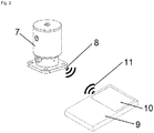
- the Figure 2 shows an arrangement of an inventive device for diagnosing a membrane in a membrane valve 7.
- the membrane is arranged in the lower part of the membrane valve 7.
- the corresponding coils for recording the state variables and possibly for improving the signal transmission are also located there.
- An external evaluation unit 9 with a corresponding display means 10 transmits electromagnetic energy to the contact coil in the membrane by means of a received signal 11. This provides the prerequisite for a measurement of at least one state variable in the membrane 1, which in turn is sent back to the evaluation unit 9 by the transmission signal 8. There, the received signal is evaluated and the value of the corresponding state variable is output on the display unit 10.
- the Figure 3 shows a comparable structure, here the evaluation unit 9 with the display means 10 is directly connected to the diaphragm valve 7.
- the contact between the membrane 1 and the evaluation unit 9 also takes place here through a transmission signal 8 from the membrane and a reception signal 11 at the evaluation unit.
- LIST OF REFERENCE NUMBERS 1 membrane 8th send signal 2 cloth 9 evaluation 3 screw 10 display means 4 chambering 11 receive signal 5 sensor 6 clockspring 7 diaphragm valve
Landscapes
- Engineering & Computer Science (AREA)
- General Engineering & Computer Science (AREA)
- Mechanical Engineering (AREA)
- Physics & Mathematics (AREA)
- General Physics & Mathematics (AREA)
- Indication Of The Valve Opening Or Closing Status (AREA)
Abstract
Description
- Die Erfindung betrifft ein Verfahren und eine Einheit zur Diagnose von Membranen in Ventilen oder Pumpen.
- Die Überwachung oder Diagnose von Membranen in Ventilen und Pumpen ist insbesondere in kritischen Bereichen der sterilen Verfahrenstechnik ein deutlicher Schwerpunkt, dem im Wesentlichen durch vorsorgende Maßnahmen begegnet wird, da fortlaufend gemessene Zustandsgrößen weitestgehend nicht verfügbar sind. Messungen während des laufenden Betriebes sind teilweise nur schwer möglich. Anlagen müssen oft in allen Details steril reinigbar aufgebaut sein, weshalb übliche elektrische Stecker Anordnungen ungünstig sind.
- In der
DE 10 2015 210 204 A1 wird ein Verfahren und eine Vorrichtung zum Auslesen und Sammeln von Daten aus einer Membran beschrieben. - Die
DE 10 2015 210 210 A1 beschreibt ein Verfahren und eine Vorrichtung zur Diagnose eines Membranventils. - Die
DE 10 2015 210 208 A1 beschreibt die Ermittlung von Zustandsgrößen bei Ventilmembranen. - Aufgabe der Erfindung ist es, eine Erfassung von Zustandsgrößen einer Membran für Ventile und Pumpen zu schaffen, bei der mindestens ein Sensor zur Ermittlung von mindestens einer Zustandsgröße und eine Übermittlung zu einem externen Erfassungsmittel vorgesehen sind.
- Diese Aufgabe wird erfindungsgemäß durch eine Vorrichtung mit den Merkmalen des Anspruchs 1 gelöst.
- Bei der Vorrichtung zur Diagnose einer Membran eines Membranventils oder einer Membranpumpe umfassend ein erstes Bauteil, bestehend aus einer in einem Gehäuse vorgesehenen Membran, wobei ein Teil der Membran aus dem Gehäuse herausragt, und ein zweites Bauteil, bestehend aus einem Datenerfassungsgerät, wobei in der Membran ein Sensor zur Erfassung von Betriebsparametern vorgesehen ist, wobei in der Membran ein Mittel zur elektromagnetischen Nahfeldkommunikation mit dem Datenerfassungsgerät vorgesehen ist. Von Vorteil ist dabei, dass das erste und das zweite Bauteil voneinander getrennt sind, wodurch es einfach, universell und kostengünstig konstruierbar ist.
- In einer weiteren Ausgestaltung ist die erfindungsgemäße Vorrichtung in der Membran als eine mechanische Verstärkungsstruktur vorgesehen, wobei die mechanische Verstärkungsstruktur aus elektrisch leitfähigem Material ausgeführt ist. Dies hat den Vorteil, dass mit einer Struktur, die in die Membran eingearbeitet ist, mehrere Zwecke verbunden werden. Auch hier zeigt sich der Vorteil bei der Einfachheit und den Kosten der Herstellung der Membran.
- In einer weiteren vorteilhaften Ausgestaltung weist die Verstärkung die Gestalt oder sonstige Eigenschaften eines Sensors auf. Vorteilhaft ist dabei, dass sich Zustandsgrößen direkt in der Membran ermitteln lassen.
- In einer weiteren Ausgestaltung weist die Verstärkungsstruktur Eigenschaften einer Nahfeldkommunikationsantenne auf. Der Vorteil dabei ist, dass die metallisch leitende Verstärkungsstruktur in ihren Dimensionen so ausgestaltet ist, dass sie für den Empfang und das Senden von Funksignalen vorbereitet ist.
- Die Erfindung umfasst weiter ein Verfahren zur Erfassung von Betriebsparametern einer Membran eines Membranventils oder einer Membranpumpe mittels einer erfindungsgemäßen, beschriebenen Vorrichtung, wobei in einem ersten Schritt das Datenerfassungsgerät in elektromagnetischen Kontakt mit der Nahfeldkommunikationsantenne gebracht wird, in einem zweiten Schritt eine Energieübertagung von dem Datenerfassungsgerät in die Membran stattfindet, wobei mittels der übertragenen Energie der Sensor aktiviert und eine Messung ausgeführt wird, in einem dritten Schritt die Messdaten mittels elektromagnetischer Nahfeldkommunikation auf das Datenerfassungsgerät übertragen werden.
- Vorteil hierbei ist, dass in der Membran keine eigene Energiequelle benötigt wird. Die Membran kann einfach und kostengünstig hergestellt werden, die Erfassung von Zustandsgrößen ist einfach, schnell und sicher durchführbar. Insbesondere ist die Sicherheit bei einer derartigen Nahfeldkommunikation erhöht, da keine weitreichenden Funksignale verwendet werden.
- Durch die drahtlose Übertragung von Energie und Informationen werden keine Kabelverbindung und kein Stecksystem benötigt. Daher muss dieses auch nicht entsprechend der Anforderungen des Einsatzbereiches ausgeführt werden. Weiterhin entsteht beim Membranwechsel keine erhöhter Aufwand durch das Anstecken der Membran an die Auswerteeinheit.
- Je nach Anwendungsfall kann entschieden werden ob die Membran kontinuierlich oder intervallbasiert überwacht werden soll. Die kontinuierliche Überwachung eignet sich für kritische und hochbelastete Geräte. Die intervallbasierte Überwachung kann mit einem mobilen Handgerät erfolgen. In diesem Fall wird die Auswerteeinheit nur einmalig benötigt.
- Weitere Merkmale und Vorteile der Erfindung ergeben sich aus der Beschreibung von Ausführungsbeispielen anhand von Zeichnungen und aus den Zeichnungen selbst.
- Dabei zeigt:
-
Figur 1 eine erfindungsgemäße Datenübertragungsvorrichtung, -
Figur 2 eine erste Ausführungsform zur Anwendung der erfindungsgemäßen Datenübertragung und -
Figur 3 eine weitere Ausführungsform zur Anwendung der erfindungsgemäßen Datenübertragung. -
Figur 1 zeigt eine Membran 1, wie sie beispielsweise in einem Membranventil zur Anwendung kommt. Die Membran 1 verfügt über einen sogenannten Lappen 2 und eine Schraube 3. Bei der dargestellten Membran liegt eine spezielle Form vor, die durch eine Kammerung 4 für zusätzliche Vorteile sorgt. In denFiguren 1b und 1c ist diese Kammerung 4 an der entsprechenden Stufe in der Membran 1 zu erkennen. - Die Membran 1 wird in einem Ventilgehäuse befestigt und durch einen an der Schraube 3 befestigten Aktor bewegt, wodurch sich das Ventil öffnen oder schließen lässt.
- In einer erfindungsgemäßen Membran 1 ist eine Verstärkungsstruktur in Form einer Spule aus einem elektrisch leitfähigen Material vorgesehen, die als Sensor 5 zur Erfassung von Zustandsgrößen auf der Fluidseite der Membran geeignet ist. Dieser Sensor 5 kann direkt durch ein externes elektromagnetisches Wechselfeld angesprochen werden, indem Wechselwirkungen eines von außen angelegten Feldes mit dem Sensor ausgewertet werden.
- Die
Figur 1 zeigt weiter eine zusätzliche Kontaktspule 6, die vorzugsweise im Lappen 2 angeordnet ist. Diese Spule kann die beschriebene Wechselwirkung eines äußeren elektromagnetischen Feldes mit der Sensorspule stark verbessern, insbesondere wenn die Membran in der Anwendung im Ventilgehäuse elektromagnetisch abgeschirmt ist. - Die
Figur 2 zeigt eine Anordnung einer erfindungsgemäßen Vorrichtung zur Diagnose einer Membran in einem Membranventil 7. Die Membran ist im unteren Teil des Membranventils 7 angeordnet. Dort befinden sich auch die entsprechenden Spulen zur Erfassung der Zustandsgrößen und eventuell zur Verbesserung der Signalübertragung. Durch eine externe Auswerteeinheit 9 mit einem entsprechenden Anzeigemittel 10 wird durch ein Empfangssignal 11 elektromagnetisch Energie auf die Kontaktspule in der Membran übertragen. Diese liefert die Voraussetzung für eine Messung mindestens einer Zustandsgröße in der Membran 1, die wiederum durch das Sendesignal 8 an die Auswerteeinheit 9 zurückgesendet wird. Dort wird das empfangene Signal ausgewertet und der Wert der entsprechenden Zustandsgröße auf der Anzeigeeinheit 10 ausgegeben. - Die
Figur 3 zeigt einen vergleichbaren Aufbau, wobei hier die Auswerteeinheit 9 mit dem Anzeigemittel 10 direkt mit dem Membranventil 7 fest verbunden ist. Der Kontakt zwischen der Membran 1 und der Auswerteeinheit 9 erfolgt auch hier durch ein Sendesignal 8 aus der Membran und ein Empfangssignal 11 an der Auswerteeinheit.Bezugszeichenliste: 1 Membran 8 Sendesignal 2 Lappen 9 Auswerteeinheit 3 Schraube 10 Anzeigemittel 4 Kammerung 11 Empfangssignal 5 Sensor 6 Kontaktspule 7 Membranventil
Claims (5)
- Vorrichtung zur Diagnose einer Membran (1) eines Membranventils (7) oder einer Membranpumpe umfassend ein erstes Bauteil, bestehend aus einer in einem Gehäuse vorgesehenen Membran, wobei ein Teil der Membran aus dem Gehäuse herausragt, und ein zweites Bauteil, bestehend aus einem Datenerfassungsgerät
dadurch gekennzeichnet, dass
in der Membran (1) mindestens ein Sensor (5) zur Erfassung von Betriebsparametern vorgesehen ist, wobei in der Membran (1) mindestens ein Mittel zur elektromagnetischen Nahfeldkommunikation mit dem Datenerfassungsgerät (9) vorgesehen ist. - Vorrichtung nach Anspruch 1, dadurch gekennzeichnet, dass in der Membran (1) eine mechanische Verstärkungsstruktur vorgesehen ist, wobei die mechanische Verstärkungsstruktur aus elektrisch leitfähigem Material ausgeführt ist.
- Vorrichtung nach Anspruch 1 oder 2, dadurch gekennzeichnet, dass die Verstärkungsstruktur die Eigenschaften eines Sensors (5) aufweist.
- Vorrichtung nach einen der Ansprüche 1 bis 3, dadurch gekennzeichnet, dass die Verstärkungsstruktur die Eigenschaften einer elektromagnetischen Nahfeldkommunikationsantenne (6) aufweist.
- Verfahren zur Erfassung von Betriebsparametern einer Membran (1) eines Membranventils (7) oder einer Membranpumpe mittels einer Vorrichtung nach einem der vorherigen Ansprüche, dadurch gekennzeichnet, dass in einem ersten Schritt das Datenerfassungsgerät (9) in elektromagnetischen Kontakt mit der Nahfeldkommunikationsantenne (6) gebracht wird, in einem zweiten Schritt eine Energieübertagung von dem Datenerfassungsgerät (9) in die Membran (1) stattfindet, wobei mittels der übertragenen Energie der Sensor (5) aktiviert und eine Messung ausgeführt wird, in einem dritten Schritt die Messdaten mittels elektromagnetischer Nahfeldkommunikation auf das Datenerfassungsgerät (9) übertragen werden.
Priority Applications (1)
| Application Number | Priority Date | Filing Date | Title |
|---|---|---|---|
| EP18187184.9A EP3604876B2 (de) | 2018-08-03 | 2018-08-03 | Membrandiagnose über luftschnittstelle |
Applications Claiming Priority (1)
| Application Number | Priority Date | Filing Date | Title |
|---|---|---|---|
| EP18187184.9A EP3604876B2 (de) | 2018-08-03 | 2018-08-03 | Membrandiagnose über luftschnittstelle |
Publications (3)
| Publication Number | Publication Date |
|---|---|
| EP3604876A1 true EP3604876A1 (de) | 2020-02-05 |
| EP3604876B1 EP3604876B1 (de) | 2021-03-10 |
| EP3604876B2 EP3604876B2 (de) | 2024-04-03 |
Family
ID=63144856
Family Applications (1)
| Application Number | Title | Priority Date | Filing Date |
|---|---|---|---|
| EP18187184.9A Active EP3604876B2 (de) | 2018-08-03 | 2018-08-03 | Membrandiagnose über luftschnittstelle |
Country Status (1)
| Country | Link |
|---|---|
| EP (1) | EP3604876B2 (de) |
Cited By (3)
| Publication number | Priority date | Publication date | Assignee | Title |
|---|---|---|---|---|
| CN115370819A (zh) * | 2022-08-11 | 2022-11-22 | 苏州协昌环保科技股份有限公司 | 电磁脉冲阀用膜片组件及含有其的电磁脉冲阀 |
| EP4119819A1 (de) * | 2020-10-06 | 2023-01-18 | SISTO Armaturen S.A. | Membrananordnung mit verstaerkungselementen |
| EP3604876B2 (de) † | 2018-08-03 | 2024-04-03 | SISTO Armaturen S.A. | Membrandiagnose über luftschnittstelle |
Citations (6)
| Publication number | Priority date | Publication date | Assignee | Title |
|---|---|---|---|---|
| US20080202606A1 (en) * | 2007-02-27 | 2008-08-28 | O'hara Dennis E | Methods and apparatus to monitor diaphragm condition |
| DE102015210210A1 (de) | 2015-06-02 | 2016-12-08 | Gemü Gebr. Müller Apparatebau Gmbh & Co. Kommanditgesellschaft | Verfahren zur Diagnose eines Membranventils, sowie Diagnosesystem für ein Membranventil |
| DE102015210208A1 (de) | 2015-06-02 | 2016-12-08 | Gemü Gebr. Müller Apparatebau Gmbh & Co. Kommanditgesellschaft | Verfahren zum Ermitteln einer Zustandsgröße einer Ventilmembran eines elektronisch gesteuerten und motorisch angetriebenen Membranventils, sowie Membranventilsystem |
| DE102015210204A1 (de) | 2015-06-02 | 2016-12-08 | Gemü Gebr. Müller Apparatebau Gmbh & Co. Kommanditgesellschaft | Verfahren zum Betreiben eines Membranventils, sowie System und Ausleseeinrichtung |
| US20170005406A1 (en) * | 2014-03-19 | 2017-01-05 | Gemu Gebr. Muller Apparatebau Gmbh & Co. Kommanditgesellschaft | Diaphragm and method for the production thereof |
| WO2017140418A1 (de) * | 2016-02-17 | 2017-08-24 | Timmer Gmbh | Membranpumpe, membran für eine membranpumpe und verfahren zum nachweis einer defekten membran einer membranpumpe |
Family Cites Families (26)
| Publication number | Priority date | Publication date | Assignee | Title |
|---|---|---|---|---|
| US4569634A (en) | 1984-09-27 | 1986-02-11 | Mantell Myron E | Failure sensing diaphragm for a diaphragm pump |
| US4781535A (en) | 1987-11-13 | 1988-11-01 | Pulsafeeder, Inc. | Apparatus and method for sensing diaphragm failures in reciprocating pumps |
| AU5352594A (en) | 1993-08-23 | 1995-03-21 | W.L. Gore & Associates, Inc. | Pre-failure warning pump diaphragm |
| DE4446304A1 (de) | 1994-12-23 | 1996-06-27 | Norton Pampus Gmbh | Membran |
| US5560279A (en) | 1995-03-16 | 1996-10-01 | W. L. Gore & Associates, Inc. | Pre-failure sensing diaphragm |
| DE19829084B4 (de) | 1998-06-30 | 2005-01-13 | Prominent Dosiertechnik Gmbh | Membranpumpe |
| DE19925508A1 (de) | 1999-06-04 | 2000-12-21 | Freudenberg Carl Fa | Einrichtung zur Erkennung von Undichtheiten an Membranen |
| DE10024118A1 (de) | 2000-05-18 | 2001-11-29 | Freudenberg Carl Fa | Einrichtung zur Überwachung der Unversehrtheit einer Membran |
| JP2002168176A (ja) | 2000-12-04 | 2002-06-14 | Tacmina Corp | ダイヤフラム、該ダイヤフラムを備えた流体制御装置及びダイヤフラムの破損検出方法 |
| DE20206914U1 (de) | 2002-05-02 | 2002-08-08 | KVS Krutina Vakuumservice, 71642 Ludwigsburg | Membran für Ventile, Pumpen u.dgl. |
| DE10323059A1 (de) | 2003-05-20 | 2004-12-09 | Prominent Dosiertechnik Gmbh | Sensormembran |
| WO2005036039A1 (en) | 2003-10-03 | 2005-04-21 | Swagelok Company | Diaphragm monitoring for flow control devices |
| US6941853B2 (en) | 2003-12-02 | 2005-09-13 | Wanner Engineering, Inc. | Pump diaphragm rupture detection |
| DE102006039501A1 (de) | 2006-08-23 | 2008-03-27 | Siemens Ag | Berührungsloser Drucksensor |
| DE102009023012A1 (de) | 2009-05-28 | 2010-12-16 | G.S. Anderson Gmbh | Membranventil-Membran |
| CN102549324B (zh) | 2009-07-31 | 2014-08-13 | Bs&B安全系统有限公司 | 泄压装置完整性传感器 |
| US8874383B2 (en) | 2009-09-03 | 2014-10-28 | Schlumberger Technology Corporation | Pump assembly |
| DE102009052244A1 (de) | 2009-11-06 | 2011-05-12 | Carl Freudenberg Kg | Sensierende Membran |
| CN103026066A (zh) | 2010-08-09 | 2013-04-03 | 凯希特许有限公司 | 用于测量由压电泵施加的压力的系统以及方法 |
| DE102010049564A1 (de) | 2010-10-25 | 2012-04-26 | Daimler Ag | Vorrichtung zum Erfassen einer mechanischen Schädigung eines Bauteils |
| US9422934B2 (en) | 2012-02-10 | 2016-08-23 | Kci Licensing, Inc. | Systems and methods for monitoring a disc pump system using RFID |
| JP6271871B2 (ja) | 2013-06-04 | 2018-01-31 | 株式会社フジキン | ダイヤフラム弁 |
| KR101519385B1 (ko) | 2013-07-15 | 2015-05-13 | 후성정공 주식회사 | 누수감지 기능을 구비한 다이아프램 밸브 |
| DE102013214304A1 (de) | 2013-07-22 | 2015-01-22 | Gemü Gebr. Müller Apparatebau Gmbh & Co. Kommanditgesellschaft | Membran und Verfahren zu deren Herstellung |
| DE102017131101B4 (de) | 2017-12-22 | 2023-04-20 | Bürkert Werke GmbH & Co. KG | Ventilbaugruppe |
| EP3604876B2 (de) † | 2018-08-03 | 2024-04-03 | SISTO Armaturen S.A. | Membrandiagnose über luftschnittstelle |
-
2018
- 2018-08-03 EP EP18187184.9A patent/EP3604876B2/de active Active
Patent Citations (6)
| Publication number | Priority date | Publication date | Assignee | Title |
|---|---|---|---|---|
| US20080202606A1 (en) * | 2007-02-27 | 2008-08-28 | O'hara Dennis E | Methods and apparatus to monitor diaphragm condition |
| US20170005406A1 (en) * | 2014-03-19 | 2017-01-05 | Gemu Gebr. Muller Apparatebau Gmbh & Co. Kommanditgesellschaft | Diaphragm and method for the production thereof |
| DE102015210210A1 (de) | 2015-06-02 | 2016-12-08 | Gemü Gebr. Müller Apparatebau Gmbh & Co. Kommanditgesellschaft | Verfahren zur Diagnose eines Membranventils, sowie Diagnosesystem für ein Membranventil |
| DE102015210208A1 (de) | 2015-06-02 | 2016-12-08 | Gemü Gebr. Müller Apparatebau Gmbh & Co. Kommanditgesellschaft | Verfahren zum Ermitteln einer Zustandsgröße einer Ventilmembran eines elektronisch gesteuerten und motorisch angetriebenen Membranventils, sowie Membranventilsystem |
| DE102015210204A1 (de) | 2015-06-02 | 2016-12-08 | Gemü Gebr. Müller Apparatebau Gmbh & Co. Kommanditgesellschaft | Verfahren zum Betreiben eines Membranventils, sowie System und Ausleseeinrichtung |
| WO2017140418A1 (de) * | 2016-02-17 | 2017-08-24 | Timmer Gmbh | Membranpumpe, membran für eine membranpumpe und verfahren zum nachweis einer defekten membran einer membranpumpe |
Cited By (4)
| Publication number | Priority date | Publication date | Assignee | Title |
|---|---|---|---|---|
| EP3604876B2 (de) † | 2018-08-03 | 2024-04-03 | SISTO Armaturen S.A. | Membrandiagnose über luftschnittstelle |
| EP4119819A1 (de) * | 2020-10-06 | 2023-01-18 | SISTO Armaturen S.A. | Membrananordnung mit verstaerkungselementen |
| CN115370819A (zh) * | 2022-08-11 | 2022-11-22 | 苏州协昌环保科技股份有限公司 | 电磁脉冲阀用膜片组件及含有其的电磁脉冲阀 |
| CN115370819B (zh) * | 2022-08-11 | 2023-11-14 | 苏州协昌环保科技股份有限公司 | 电磁脉冲阀用膜片组件及含有其的电磁脉冲阀 |
Also Published As
| Publication number | Publication date |
|---|---|
| EP3604876B2 (de) | 2024-04-03 |
| EP3604876B1 (de) | 2021-03-10 |
Similar Documents
| Publication | Publication Date | Title |
|---|---|---|
| EP3604876B2 (de) | Membrandiagnose über luftschnittstelle | |
| DE102018213002A1 (de) | Vorrichtung und Verfahren zur Diagnose von Membranen | |
| DE102017131101B4 (de) | Ventilbaugruppe | |
| DE102015210210B4 (de) | Verfahren zur Diagnose eines Membranventils, sowie Diagnosesystem für ein Membranventil | |
| EP3126696A1 (de) | Modulares aktorkonzept für kupplungsaktor | |
| DE102017118566A1 (de) | Erfassungssystem zur Detektion einer Betätigung bei einer Griffvorrichtung eines Fahrzeuges | |
| DE4413098A1 (de) | Meßsystem für Linear- oder Angularbewegungen | |
| EP3748307B1 (de) | Feldgerät mit befestigungsadapter | |
| DE102010041170A1 (de) | Ventilbaugruppe mit Rückschlagventil und Druckaufnehmer für ein Kraftfahrzeug | |
| DE102017007818A1 (de) | Ladevorrichtung zum Laden eines elektrischen Energiespeichers eines Kraftfahrzeugs, Kraftfahrzeug sowie Ladesystem | |
| DE102018217118B4 (de) | Verfahren zum Erstellen einer Fehlerdiagnose eines Antriebsstrangs eines elektrisch betriebenen Kraftfahrzeugs und Kraftfahrzeug | |
| DE102015111901B4 (de) | Anordnung und Verfahren zur Drehmomentmessung für Kompressoren | |
| DE3812631C1 (en) | Device for contactless interrogation of the state of electrical switching or triggering means in a motor vehicle | |
| DE102017121094A1 (de) | Ventilsteuerkopf | |
| DE202013009042U1 (de) | Sensortelemetrie mit integriertem Komplettmonitoring und Remotesteuerfunktion für Anwendung zur kontaktlosen Sensordatenübertragung | |
| DE102015010042A1 (de) | Prüfanordnung zur Prüfung mindestens einer Verbindungsschnittstelle und Verfahren zur Prüfung mindestens einer Verbindungsschnittstelle mit einer Prüfanordnung | |
| DE202018104129U1 (de) | Durchfluss-Anzeige an Membranplatten in Filterpressen | |
| DE3609564A1 (de) | Filterpresse mit membranplatten | |
| DE102011050007A1 (de) | Stellungsregler | |
| DE102010062584A1 (de) | Kabellose Energie- und Signalübertragung ein einem beweglichen Sensorsystem | |
| WO2015110476A1 (de) | Verbindungsadaptersystem der steuerungstechnik | |
| WO2022117146A1 (de) | Sensoreinheit zur ausbildung eines sensorknotens in einem drahtlosen sensornetzwerk und drahtloses sensornetzwerk umfassend einen solchen sensorknoten | |
| DE102007035569A1 (de) | Anordnung zur Bestimmung und/oder Einstellung der Patientenposition in Therapie- und/oder Diagnosegeräten | |
| DE102017128509A1 (de) | Gekapselter Magnetpositionsschalter | |
| DE102015002167A1 (de) | Verfahren und System zur Höhenmessung in einem Fahrzeug |
Legal Events
| Date | Code | Title | Description |
|---|---|---|---|
| PUAI | Public reference made under article 153(3) epc to a published international application that has entered the european phase |
Free format text: ORIGINAL CODE: 0009012 |
|
| STAA | Information on the status of an ep patent application or granted ep patent |
Free format text: STATUS: THE APPLICATION HAS BEEN PUBLISHED |
|
| AK | Designated contracting states |
Kind code of ref document: A1 Designated state(s): AL AT BE BG CH CY CZ DE DK EE ES FI FR GB GR HR HU IE IS IT LI LT LU LV MC MK MT NL NO PL PT RO RS SE SI SK SM TR |
|
| AX | Request for extension of the european patent |
Extension state: BA ME |
|
| STAA | Information on the status of an ep patent application or granted ep patent |
Free format text: STATUS: REQUEST FOR EXAMINATION WAS MADE |
|
| 17P | Request for examination filed |
Effective date: 20200805 |
|
| RBV | Designated contracting states (corrected) |
Designated state(s): AL AT BE BG CH CY CZ DE DK EE ES FI FR GB GR HR HU IE IS IT LI LT LU LV MC MK MT NL NO PL PT RO RS SE SI SK SM TR |
|
| GRAP | Despatch of communication of intention to grant a patent |
Free format text: ORIGINAL CODE: EPIDOSNIGR1 |
|
| STAA | Information on the status of an ep patent application or granted ep patent |
Free format text: STATUS: GRANT OF PATENT IS INTENDED |
|
| RIC1 | Information provided on ipc code assigned before grant |
Ipc: F16K 37/00 20060101AFI20200918BHEP Ipc: F04B 51/00 20060101ALI20200918BHEP Ipc: F16K 7/12 20060101ALI20200918BHEP Ipc: F04B 43/00 20060101ALI20200918BHEP Ipc: F16J 3/02 20060101ALI20200918BHEP Ipc: G01M 99/00 20110101ALI20200918BHEP |
|
| INTG | Intention to grant announced |
Effective date: 20201014 |
|
| GRAS | Grant fee paid |
Free format text: ORIGINAL CODE: EPIDOSNIGR3 |
|
| GRAA | (expected) grant |
Free format text: ORIGINAL CODE: 0009210 |
|
| STAA | Information on the status of an ep patent application or granted ep patent |
Free format text: STATUS: THE PATENT HAS BEEN GRANTED |
|
| AK | Designated contracting states |
Kind code of ref document: B1 Designated state(s): AL AT BE BG CH CY CZ DE DK EE ES FI FR GB GR HR HU IE IS IT LI LT LU LV MC MK MT NL NO PL PT RO RS SE SI SK SM TR |
|
| REG | Reference to a national code |
Ref country code: GB Ref legal event code: FG4D Free format text: NOT ENGLISH |
|
| REG | Reference to a national code |
Ref country code: AT Ref legal event code: REF Ref document number: 1370174 Country of ref document: AT Kind code of ref document: T Effective date: 20210315 Ref country code: CH Ref legal event code: EP |
|
| REG | Reference to a national code |
Ref country code: IE Ref legal event code: FG4D Free format text: LANGUAGE OF EP DOCUMENT: GERMAN |
|
| REG | Reference to a national code |
Ref country code: DE Ref legal event code: R096 Ref document number: 502018004222 Country of ref document: DE |
|
| REG | Reference to a national code |
Ref country code: LT Ref legal event code: MG9D |
|
| PG25 | Lapsed in a contracting state [announced via postgrant information from national office to epo] |
Ref country code: LT Free format text: LAPSE BECAUSE OF FAILURE TO SUBMIT A TRANSLATION OF THE DESCRIPTION OR TO PAY THE FEE WITHIN THE PRESCRIBED TIME-LIMIT Effective date: 20210310 Ref country code: NO Free format text: LAPSE BECAUSE OF FAILURE TO SUBMIT A TRANSLATION OF THE DESCRIPTION OR TO PAY THE FEE WITHIN THE PRESCRIBED TIME-LIMIT Effective date: 20210610 Ref country code: BG Free format text: LAPSE BECAUSE OF FAILURE TO SUBMIT A TRANSLATION OF THE DESCRIPTION OR TO PAY THE FEE WITHIN THE PRESCRIBED TIME-LIMIT Effective date: 20210610 Ref country code: GR Free format text: LAPSE BECAUSE OF FAILURE TO SUBMIT A TRANSLATION OF THE DESCRIPTION OR TO PAY THE FEE WITHIN THE PRESCRIBED TIME-LIMIT Effective date: 20210611 Ref country code: FI Free format text: LAPSE BECAUSE OF FAILURE TO SUBMIT A TRANSLATION OF THE DESCRIPTION OR TO PAY THE FEE WITHIN THE PRESCRIBED TIME-LIMIT Effective date: 20210310 Ref country code: HR Free format text: LAPSE BECAUSE OF FAILURE TO SUBMIT A TRANSLATION OF THE DESCRIPTION OR TO PAY THE FEE WITHIN THE PRESCRIBED TIME-LIMIT Effective date: 20210310 |
|
| REG | Reference to a national code |
Ref country code: NL Ref legal event code: MP Effective date: 20210310 |
|
| PG25 | Lapsed in a contracting state [announced via postgrant information from national office to epo] |
Ref country code: SE Free format text: LAPSE BECAUSE OF FAILURE TO SUBMIT A TRANSLATION OF THE DESCRIPTION OR TO PAY THE FEE WITHIN THE PRESCRIBED TIME-LIMIT Effective date: 20210310 Ref country code: LV Free format text: LAPSE BECAUSE OF FAILURE TO SUBMIT A TRANSLATION OF THE DESCRIPTION OR TO PAY THE FEE WITHIN THE PRESCRIBED TIME-LIMIT Effective date: 20210310 Ref country code: RS Free format text: LAPSE BECAUSE OF FAILURE TO SUBMIT A TRANSLATION OF THE DESCRIPTION OR TO PAY THE FEE WITHIN THE PRESCRIBED TIME-LIMIT Effective date: 20210310 |
|
| PG25 | Lapsed in a contracting state [announced via postgrant information from national office to epo] |
Ref country code: NL Free format text: LAPSE BECAUSE OF FAILURE TO SUBMIT A TRANSLATION OF THE DESCRIPTION OR TO PAY THE FEE WITHIN THE PRESCRIBED TIME-LIMIT Effective date: 20210310 |
|
| PG25 | Lapsed in a contracting state [announced via postgrant information from national office to epo] |
Ref country code: SM Free format text: LAPSE BECAUSE OF FAILURE TO SUBMIT A TRANSLATION OF THE DESCRIPTION OR TO PAY THE FEE WITHIN THE PRESCRIBED TIME-LIMIT Effective date: 20210310 Ref country code: EE Free format text: LAPSE BECAUSE OF FAILURE TO SUBMIT A TRANSLATION OF THE DESCRIPTION OR TO PAY THE FEE WITHIN THE PRESCRIBED TIME-LIMIT Effective date: 20210310 Ref country code: CZ Free format text: LAPSE BECAUSE OF FAILURE TO SUBMIT A TRANSLATION OF THE DESCRIPTION OR TO PAY THE FEE WITHIN THE PRESCRIBED TIME-LIMIT Effective date: 20210310 |
|
| PG25 | Lapsed in a contracting state [announced via postgrant information from national office to epo] |
Ref country code: SK Free format text: LAPSE BECAUSE OF FAILURE TO SUBMIT A TRANSLATION OF THE DESCRIPTION OR TO PAY THE FEE WITHIN THE PRESCRIBED TIME-LIMIT Effective date: 20210310 Ref country code: PT Free format text: LAPSE BECAUSE OF FAILURE TO SUBMIT A TRANSLATION OF THE DESCRIPTION OR TO PAY THE FEE WITHIN THE PRESCRIBED TIME-LIMIT Effective date: 20210712 Ref country code: PL Free format text: LAPSE BECAUSE OF FAILURE TO SUBMIT A TRANSLATION OF THE DESCRIPTION OR TO PAY THE FEE WITHIN THE PRESCRIBED TIME-LIMIT Effective date: 20210310 Ref country code: RO Free format text: LAPSE BECAUSE OF FAILURE TO SUBMIT A TRANSLATION OF THE DESCRIPTION OR TO PAY THE FEE WITHIN THE PRESCRIBED TIME-LIMIT Effective date: 20210310 Ref country code: IS Free format text: LAPSE BECAUSE OF FAILURE TO SUBMIT A TRANSLATION OF THE DESCRIPTION OR TO PAY THE FEE WITHIN THE PRESCRIBED TIME-LIMIT Effective date: 20210710 |
|
| REG | Reference to a national code |
Ref country code: DE Ref legal event code: R026 Ref document number: 502018004222 Country of ref document: DE |
|
| PLBI | Opposition filed |
Free format text: ORIGINAL CODE: 0009260 |
|
| PLAX | Notice of opposition and request to file observation + time limit sent |
Free format text: ORIGINAL CODE: EPIDOSNOBS2 |
|
| 26 | Opposition filed |
Opponent name: GEMUE GEBR. MUELLER APPARATEBAU GMBH & CO. KOMMANDITGESELLSCHAFT Effective date: 20211209 |
|
| PG25 | Lapsed in a contracting state [announced via postgrant information from national office to epo] |
Ref country code: DK Free format text: LAPSE BECAUSE OF FAILURE TO SUBMIT A TRANSLATION OF THE DESCRIPTION OR TO PAY THE FEE WITHIN THE PRESCRIBED TIME-LIMIT Effective date: 20210310 Ref country code: AL Free format text: LAPSE BECAUSE OF FAILURE TO SUBMIT A TRANSLATION OF THE DESCRIPTION OR TO PAY THE FEE WITHIN THE PRESCRIBED TIME-LIMIT Effective date: 20210310 Ref country code: ES Free format text: LAPSE BECAUSE OF FAILURE TO SUBMIT A TRANSLATION OF THE DESCRIPTION OR TO PAY THE FEE WITHIN THE PRESCRIBED TIME-LIMIT Effective date: 20210310 |
|
| PG25 | Lapsed in a contracting state [announced via postgrant information from national office to epo] |
Ref country code: SI Free format text: LAPSE BECAUSE OF FAILURE TO SUBMIT A TRANSLATION OF THE DESCRIPTION OR TO PAY THE FEE WITHIN THE PRESCRIBED TIME-LIMIT Effective date: 20210310 |
|
| PLBB | Reply of patent proprietor to notice(s) of opposition received |
Free format text: ORIGINAL CODE: EPIDOSNOBS3 |
|
| PG25 | Lapsed in a contracting state [announced via postgrant information from national office to epo] |
Ref country code: MC Free format text: LAPSE BECAUSE OF FAILURE TO SUBMIT A TRANSLATION OF THE DESCRIPTION OR TO PAY THE FEE WITHIN THE PRESCRIBED TIME-LIMIT Effective date: 20210310 |
|
| REG | Reference to a national code |
Ref country code: BE Ref legal event code: MM Effective date: 20210831 |
|
| PG25 | Lapsed in a contracting state [announced via postgrant information from national office to epo] |
Ref country code: IT Free format text: LAPSE BECAUSE OF FAILURE TO SUBMIT A TRANSLATION OF THE DESCRIPTION OR TO PAY THE FEE WITHIN THE PRESCRIBED TIME-LIMIT Effective date: 20210310 |
|
| PG25 | Lapsed in a contracting state [announced via postgrant information from national office to epo] |
Ref country code: IS Free format text: LAPSE BECAUSE OF FAILURE TO SUBMIT A TRANSLATION OF THE DESCRIPTION OR TO PAY THE FEE WITHIN THE PRESCRIBED TIME-LIMIT Effective date: 20210710 Ref country code: LU Free format text: LAPSE BECAUSE OF NON-PAYMENT OF DUE FEES Effective date: 20210803 |
|
| PG25 | Lapsed in a contracting state [announced via postgrant information from national office to epo] |
Ref country code: IE Free format text: LAPSE BECAUSE OF NON-PAYMENT OF DUE FEES Effective date: 20210803 Ref country code: BE Free format text: LAPSE BECAUSE OF NON-PAYMENT OF DUE FEES Effective date: 20210831 |
|
| GBPC | Gb: european patent ceased through non-payment of renewal fee |
Effective date: 20220803 |
|
| PG25 | Lapsed in a contracting state [announced via postgrant information from national office to epo] |
Ref country code: CY Free format text: LAPSE BECAUSE OF FAILURE TO SUBMIT A TRANSLATION OF THE DESCRIPTION OR TO PAY THE FEE WITHIN THE PRESCRIBED TIME-LIMIT Effective date: 20210310 |
|
| PG25 | Lapsed in a contracting state [announced via postgrant information from national office to epo] |
Ref country code: HU Free format text: LAPSE BECAUSE OF FAILURE TO SUBMIT A TRANSLATION OF THE DESCRIPTION OR TO PAY THE FEE WITHIN THE PRESCRIBED TIME-LIMIT; INVALID AB INITIO Effective date: 20180803 |
|
| P01 | Opt-out of the competence of the unified patent court (upc) registered |
Effective date: 20230704 |
|
| APBM | Appeal reference recorded |
Free format text: ORIGINAL CODE: EPIDOSNREFNO |
|
| APBP | Date of receipt of notice of appeal recorded |
Free format text: ORIGINAL CODE: EPIDOSNNOA2O |
|
| APAH | Appeal reference modified |
Free format text: ORIGINAL CODE: EPIDOSCREFNO |
|
| PG25 | Lapsed in a contracting state [announced via postgrant information from national office to epo] |
Ref country code: GB Free format text: LAPSE BECAUSE OF NON-PAYMENT OF DUE FEES Effective date: 20220803 |
|
| APBU | Appeal procedure closed |
Free format text: ORIGINAL CODE: EPIDOSNNOA9O |
|
| PUAH | Patent maintained in amended form |
Free format text: ORIGINAL CODE: 0009272 |
|
| STAA | Information on the status of an ep patent application or granted ep patent |
Free format text: STATUS: PATENT MAINTAINED AS AMENDED |
|
| 27A | Patent maintained in amended form |
Effective date: 20240403 |
|
| AK | Designated contracting states |
Kind code of ref document: B2 Designated state(s): AL AT BE BG CH CY CZ DE DK EE ES FI FR GB GR HR HU IE IS IT LI LT LU LV MC MK MT NL NO PL PT RO RS SE SI SK SM TR |
|
| REG | Reference to a national code |
Ref country code: DE Ref legal event code: R102 Ref document number: 502018004222 Country of ref document: DE |
|
| PG25 | Lapsed in a contracting state [announced via postgrant information from national office to epo] |
Ref country code: MK Free format text: LAPSE BECAUSE OF FAILURE TO SUBMIT A TRANSLATION OF THE DESCRIPTION OR TO PAY THE FEE WITHIN THE PRESCRIBED TIME-LIMIT Effective date: 20210310 |
|
| PG25 | Lapsed in a contracting state [announced via postgrant information from national office to epo] |
Ref country code: MT Free format text: LAPSE BECAUSE OF FAILURE TO SUBMIT A TRANSLATION OF THE DESCRIPTION OR TO PAY THE FEE WITHIN THE PRESCRIBED TIME-LIMIT Effective date: 20210310 |
|
| PGFP | Annual fee paid to national office [announced via postgrant information from national office to epo] |
Ref country code: DE Payment date: 20250904 Year of fee payment: 8 |
|
| PGFP | Annual fee paid to national office [announced via postgrant information from national office to epo] |
Ref country code: FR Payment date: 20250826 Year of fee payment: 8 Ref country code: AT Payment date: 20250822 Year of fee payment: 8 |
|
| PGFP | Annual fee paid to national office [announced via postgrant information from national office to epo] |
Ref country code: CH Payment date: 20250901 Year of fee payment: 8 |
|
| PG25 | Lapsed in a contracting state [announced via postgrant information from national office to epo] |
Ref country code: TR Free format text: LAPSE BECAUSE OF FAILURE TO SUBMIT A TRANSLATION OF THE DESCRIPTION OR TO PAY THE FEE WITHIN THE PRESCRIBED TIME-LIMIT Effective date: 20210310 |