EP3604787A1 - Fuel rail for a fuel injection system and method of manufacturing such a fuel rail - Google Patents
Fuel rail for a fuel injection system and method of manufacturing such a fuel rail Download PDFInfo
- Publication number
- EP3604787A1 EP3604787A1 EP18187317.5A EP18187317A EP3604787A1 EP 3604787 A1 EP3604787 A1 EP 3604787A1 EP 18187317 A EP18187317 A EP 18187317A EP 3604787 A1 EP3604787 A1 EP 3604787A1
- Authority
- EP
- European Patent Office
- Prior art keywords
- fuel
- fuel rail
- sectional profile
- rail
- height
- Prior art date
- Legal status (The legal status is an assumption and is not a legal conclusion. Google has not performed a legal analysis and makes no representation as to the accuracy of the status listed.)
- Granted
Links
- 239000000446 fuel Substances 0.000 title claims abstract description 189
- 238000004519 manufacturing process Methods 0.000 title claims abstract description 13
- 238000002347 injection Methods 0.000 title claims abstract description 11
- 239000007924 injection Substances 0.000 title claims abstract description 11
- 230000002093 peripheral effect Effects 0.000 claims abstract description 28
- 238000002485 combustion reaction Methods 0.000 claims abstract description 10
- 238000000034 method Methods 0.000 claims description 10
- 239000002184 metal Substances 0.000 claims description 7
- 238000010894 electron beam technology Methods 0.000 claims description 4
- 238000010146 3D printing Methods 0.000 claims description 3
- 230000008021 deposition Effects 0.000 claims description 3
- 230000004927 fusion Effects 0.000 claims description 3
- 239000010935 stainless steel Substances 0.000 claims description 3
- 229910001220 stainless steel Inorganic materials 0.000 claims description 3
- 239000000654 additive Substances 0.000 abstract description 9
- 230000000996 additive effect Effects 0.000 abstract description 9
- 238000005516 engineering process Methods 0.000 abstract description 4
- 239000000463 material Substances 0.000 description 7
- 239000012530 fluid Substances 0.000 description 4
- 238000004891 communication Methods 0.000 description 3
- 239000000843 powder Substances 0.000 description 3
- 238000011960 computer-aided design Methods 0.000 description 2
- 239000004033 plastic Substances 0.000 description 2
- 229920003023 plastic Polymers 0.000 description 2
- 230000002787 reinforcement Effects 0.000 description 2
- 230000007704 transition Effects 0.000 description 2
- 229910000831 Steel Inorganic materials 0.000 description 1
- 229910045601 alloy Inorganic materials 0.000 description 1
- 239000000956 alloy Substances 0.000 description 1
- 238000009434 installation Methods 0.000 description 1
- 238000011068 loading method Methods 0.000 description 1
- 230000008018 melting Effects 0.000 description 1
- 238000002844 melting Methods 0.000 description 1
- 230000002028 premature Effects 0.000 description 1
- 238000007639 printing Methods 0.000 description 1
- 239000007787 solid Substances 0.000 description 1
- 239000010959 steel Substances 0.000 description 1
- 238000005728 strengthening Methods 0.000 description 1
Images

Classifications
-
- F—MECHANICAL ENGINEERING; LIGHTING; HEATING; WEAPONS; BLASTING
- F02—COMBUSTION ENGINES; HOT-GAS OR COMBUSTION-PRODUCT ENGINE PLANTS
- F02M—SUPPLYING COMBUSTION ENGINES IN GENERAL WITH COMBUSTIBLE MIXTURES OR CONSTITUENTS THEREOF
- F02M55/00—Fuel-injection apparatus characterised by their fuel conduits or their venting means; Arrangements of conduits between fuel tank and pump F02M37/00
- F02M55/02—Conduits between injection pumps and injectors, e.g. conduits between pump and common-rail or conduits between common-rail and injectors
- F02M55/025—Common rails
-
- F—MECHANICAL ENGINEERING; LIGHTING; HEATING; WEAPONS; BLASTING
- F02—COMBUSTION ENGINES; HOT-GAS OR COMBUSTION-PRODUCT ENGINE PLANTS
- F02M—SUPPLYING COMBUSTION ENGINES IN GENERAL WITH COMBUSTIBLE MIXTURES OR CONSTITUENTS THEREOF
- F02M61/00—Fuel-injectors not provided for in groups F02M39/00 - F02M57/00 or F02M67/00
- F02M61/16—Details not provided for in, or of interest apart from, the apparatus of groups F02M61/02 - F02M61/14
- F02M61/168—Assembling; Disassembling; Manufacturing; Adjusting
Definitions
- the present disclosure relates to a fuel rail for a fuel injection system for an internal combustion engine and to a method of manufacturing a fuel rail.
- a fuel rail for a fuel injection system for an internal combustion engine typically comprises an elongate tubular member forming a reservoir for fuel which is supplied to an inlet of the fuel rail under high pressure by a fuel pump.
- the fuel rail has a plurality of fuel outlets spaced along its length each of which is in hydraulic communication with a fuel injector by which fuel is injected into the engine.
- each cylinder of a multi-cylinder internal combustion engine has a fuel injector which injects fuel directly into the combustion chamber.
- fuel rails When installed in a motor vehicle, such fuel rails are typically secured rigidly to the engine where they are subjected to high stresses caused by the harsh environment of high temperatures, vibration caused by the engine vibrating on its engine mounts in the vehicle and by the general vibration in the vehicle as it moves along. In addition, further stress is applied to the fuel rail by virtue of the high internal fluid pressure in the fuel rail and of pressure fluctuations caused by the fuel pump and the fuel injection process.
- holes for mounting points to enable the fuel rail to be secured to the engine and the holes in the fuel rail forming the fuel outlets inevitably form stress concentration points where the stresses on the fuel rail are greatly increased, which can lead to premature failure and lower durability at these points.
- the present disclosure provides a fuel rail which is compact, lightweight and which can be manufactured in a cost effective manner.
- a fuel rail for a fuel injection system for an internal combustion engine comprises an elongate body having a peripheral wall defining a fuel reservoir and having a fuel inlet, a plurality of fuel outlets spaced along the fuel rail, and at least one fastening point to enable the fuel rail to be secured to an engine.
- the peripheral wall has a wall thickness that is variable along length of the elongate body and is thicker in regions subject, in operation, to higher stress.
- the fuel rail includes integral local reinforcement of its strength in regions that are subject to higher stress, particularly when the fuel rail is in operation. These regions may be the fuel outlets and fastening points for example.
- the fastening point is positioned in a portion of the peripheral wall having an increased thickness to provide localised strengthening of the fuel rail and its elongate body in the region of the fastening point.
- the fastening point comprises a hole that extends through the portion of the peripheral wall having the increased thickness and that is separate from the fuel reservoir.
- the hole and, therefore, fastening point is integral with the fuel rail as it is positioned in the peripheral wall.
- the hole is integrally formed in the increased thickness of the peripheral wall and is not in hydraulic or fluid communication with the fuel reservoir.
- the portion of the peripheral wall having the increased thickness may protrude outwardly from the centre axis of the elongate body to an extent sufficient to accommodate the hole within the protruding region and to position the hole with respect to the fuel reservoir at the desired position for mounting to the engine.
- the fuel reservoir has an internal cross-sectional profile and, in some embodiments, the internal cross-sectional profile of the fuel reservoir is variable along a length of the elongate body.
- the internal cross-sectional profile of the fuel reservoir may have a height h i that extends in a direction upwards from and perpendicular to an inner opening of the fuel outlet and a width w i extending perpendicular to the height h i .
- a height h i1 of the internal cross-sectional profile of the fuel reservoir above each fuel outlet is smaller than a height h i2 of the internal cross-sectional profile between the fuel outlets.
- a width w i1 of the internal cross-sectional profile of the fuel reservoir above each fuel outlet may be greater than a width w i2 of the internal cross-sectional profile between the fuel outlets. Therefore, the internal cross-sectional profile and, in some embodiments, the cross-sectional area of the fuel reservoir may vary along the length of the fuel reservoir in order to control the fuel pressure and flow dynamics of the fuel within the reservoir, in particular with respect to the position of the fuel outlets.
- transitions between the changes in the height and width of the internal cross-section profile and cross-sectional area of the fuel reservoir are smooth in order to avoid stress concentration regions.
- the fuel rail also has an external cross-sectional profile and the external cross-sectional profile may also be variable along a length of the elongate body and fuel rail.
- the external cross-sectional profile has a height h e extending parallel the fuel outlet and a width w e extending perpendicular to the height h e .
- a height h e1 of the external cross-sectional profile of the fuel rail at each fuel outlet is smaller than a height h e2 of the external cross-sectional profile between the fuel outlets.
- a width w e1 of the external cross-sectional profile of the fuel rail at each fuel outlet may be greater than a width w e2 of the external cross-sectional profile between the fuel outlets.
- the fuel rail may have an outer contour that undulates, for example has a wave-like profile.
- the fuel rail has an undulating or wave-like profile in two perpendicular directions, for example the peaks in the height direction may be positioned at longitudinal positions along the length of the fuel rail that are intermediate peaks in the width direction.
- the fuel rail may comprise a metal, for example a steel such as a stainless steel, or may comprise plastic.
- the disclosure also describes a method of manufacturing a fuel rail for a fuel injection system for an internal combustion engine.
- the method comprising building up an elongate body of the fuel rail according to any one of the embodiments described herein layer by layer, for example using additive manufacturing.
- Additive manufacturing techniques may be used to build up the elongate body and the fuel rail layer by layer.
- the elongate body may be built up layer by layer using 3D (Three-dimensional) printing or Powder Bed Fusion or Directed Energy Deposition.
- the elongate body may be built up layer by layer by movement of the metal jet print head, laser or electron beam controlled according to a three dimensional model of the elongate body.
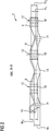
- a fuel rail 2 comprises an elongate body 4 having a peripheral wall 6 forming a reservoir 8 for fuel.
- the fuel rail 2 is formed by an additive manufacturing technology.
- the material of the fuel rail 2 is metal such as stainless steel but in other embodiments may be formed of a plastics material.
- At one end the fuel rail 2 is supplied with a fuel inlet 10 connected to a high-pressure fuel pump (not shown) by which fuel is supplied to the fuel rail 2.
- the other end of the fuel rail 2 is closed.
- the fuel rail 2 also includes one or more fixtures 12 or fuel rail mounting points 12 through which the fuel rail 2 is secured to the engine.
- the fixtures 12 may be provided in the region intermediate each fuel outlet 14 at a position determined by the installation conditions of the engine.
- the fuel rail 2 of this embodiment is adapted to provide a direct fuel injection for a three-cylinder gasoline engine and has three fuel outlets 14 spaced along the fuel rail 2, the three outlets 14 being substantially aligned along a common axis which provide a mechanical and hydraulic connection to an injector inlet port in the form of an injector cup 16 adapted to receive a fuel injector (not shown) for each cylinder.
- an injector inlet port in the form of an injector cup 16 adapted to receive a fuel injector (not shown) for each cylinder.
- the present disclosure may be adapted for use for engines having one or more cylinders, particularly for example, in designs in which the fuel is injected into the engine intake manifold.
- the fixture 12 has the form of a hole 18 that is positioned in a portion 20 of the peripheral wall 6 that has an increased thickness.
- the portion 20 may protrude outwardly from the longitudinal axis of the elongate body 4 of the fuel rail 2.
- the hole 18 and, therefore, the mounting fixture 12 of the fuel rail 2 is integrally formed in the peripheral wall 6 of the fuel rail 2.
- the hole 18 is positioned within and has side walls defined by the thickened portion 20 of the peripheral wall and open ends that are separate from and not in fluid communication with the fuel reservoir 8 defined by the inner surface of the peripheral wall 6.
- the increased thickness of the peripheral wall 6 in the region around the hole 18 provides additional localised reinforcement to increase the strength of the fuel rail 2 and mitigate any stress introduced by providing the hole 18 in the peripheral wall 6 of the fuel rail 2.
- the thickness of the peripheral wall 6 of the fuel rail 2 in the region of the mounting points 12 is increased with a smooth transition in the thickness of the peripheral wall 6 to avoid creating stress concentration zones in the peripheral wall 6. In this way, the stress forces in the peripheral wall 6 in the region of the mounting points 12 are reduced and matched more closely to the forces acting on the remainder of the fuel rail 2.
- the wall thickness in the region of the fuel outlets 14 is also increased to ensure that stress levels in the region of the fuel outlets 14 are more evenly matched to those in the remainder of the peripheral wall 8.
- This form of the fuel rail 2 has the advantage that for a given operating pressure it is possible to form the bulk of the fuel rail 2 with a thinner wall thickness. This makes it possible to lower the weight of the fuel rail 2 or to enable the fuel rail 2 to operate with higher operating pressures and stresses without increasing the weight of the fuel rail.
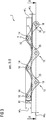
- the fuel reservoir 8 has an internal cross-sectional profile which varies in a longitudinal direction, i.e. along the length of the elongate body 2 from the fuel inlet 10 to the closed end.
- the internal cross-sectional profile has a height h i extending upwards from an inner opening of each fuel outlet 14 and a width w i extending perpendicular to the height h i . Both the height h i and the width w i vary in a longitudinal direction in an opposing manner.
- a height h i1 of the internal cross-sectional profile at a longitudinal position of the fuel rail 2 above each fuel outlet 14 is smaller than a height h i2 of the internal cross-sectional profile at a longitudinal position between the fuel outlets 14.
- a width w i1 of the internal cross-sectional profile above each fuel outlet 14 is greater than a width w i2 of the internal cross-sectional profile at a longitudinal position between the fuel outlets 14.
- the cross-section of the fuel reservoir over each fuel outlet 14 is wider and narrower to increase the flow speed and hence reduce the pressure over the fuel outlet 14 and to control the fluid dynamics at the fuel outlets 14.
- the fuel rail 2 has an external cross-sectional profile which is variable along a length of the elongate body 4.
- the external cross-sectional profile has a height h e extending parallel the fuel outlets 14 and height h i of the fuel reservoir 8 and a width w e extending perpendicular to the height h e and parallel to the width w i of the fuel reservoir 8.
- a height h e1 of the external cross-sectional profile at a longitudinal position above each fuel outlet 14 is smaller than a height h e2 of the external cross-sectional profile at a longitudinal position between the fuel outlets 14.
- a width w e1 of the external cross-sectional profile at a longitudinal position above each fuel outlet 14 is greater than a width w e2 of the external cross-sectional profile at a longitudinal position between the fuel outlets 14.
- the fuel rail 2 has an outer profile which can be considered to be undulating or have a wave-like form due to the variable cross-sectional area of the fuel reservoir 8 and variable thickness of the peripheral wall 6.
- the fuel rail 2 and the reservoir 8 has an undulating or wave-like profile in two perpendicular directions.
- the peaks in the height direction h e may be positioned at longitudinal positions along the length of the fuel rail 2 that are intermediate the peaks in the width direction w e .
- the fuel rail 2 may be formed from a metal or alloy.
- the fuel rail 2 with its fuel reservoir 8 and integral mounting fixtures 12 may be fabricated using additive manufacturing techniques. In additive manufacturing, a three-dimensional object is built up layer by layer in contrast to subtraction techniques in which a portion of a work piece is removed to form an object with the desired form.
- additive manufacturing technology sometimes called 3D printing
- 3D printing enables complex shapes including the fuel rail 2 to be formed quickly and economically compared with other techniques such as extruding or drawing material from a solid blank. It enables the wall thickness to be varied at any point in thickness and extent depending on the loadings at any point. In this way the amount of material used is minimised as the additive technique ensures that material is not deposited where it is not needed for functional purposes. Significant weight saving can be achieved.
- An example of an additive manufacturing technique is 3D printing in which material is deposited using a moving metal jet print head.
- a further example is powder bed fusion in which thermal energy from a laser of electron beam is used to selectively fuse powder in a powder bed.
- a further example is directed energy deposition in which thermal energy, for example from a laser, is used to fuse materials by melting them as they are deposited.
- the movement of the metal jet print head, laser or electron beam is computer controlled to build up an object, in this case the elongate body 4, layer by layer according to a three-dimensional model, such as a CAD (Computer Aided Design) model, of the elongate body 4.
- CAD Computer Aided Design
Abstract
Description
- The present disclosure relates to a fuel rail for a fuel injection system for an internal combustion engine and to a method of manufacturing a fuel rail.
- A fuel rail for a fuel injection system for an internal combustion engine, also known as a common rail or a main gallery, typically comprises an elongate tubular member forming a reservoir for fuel which is supplied to an inlet of the fuel rail under high pressure by a fuel pump. The fuel rail has a plurality of fuel outlets spaced along its length each of which is in hydraulic communication with a fuel injector by which fuel is injected into the engine. In one form referred to as direct injection each cylinder of a multi-cylinder internal combustion engine has a fuel injector which injects fuel directly into the combustion chamber.
- When installed in a motor vehicle, such fuel rails are typically secured rigidly to the engine where they are subjected to high stresses caused by the harsh environment of high temperatures, vibration caused by the engine vibrating on its engine mounts in the vehicle and by the general vibration in the vehicle as it moves along. In addition, further stress is applied to the fuel rail by virtue of the high internal fluid pressure in the fuel rail and of pressure fluctuations caused by the fuel pump and the fuel injection process.
- Furthermore, holes for mounting points to enable the fuel rail to be secured to the engine and the holes in the fuel rail forming the fuel outlets inevitably form stress concentration points where the stresses on the fuel rail are greatly increased, which can lead to premature failure and lower durability at these points.
- It is, therefore, desirable to provide a fuel rail which has improved mechanical behaviour and durability and which is also compact and cost effective to manufacture.
- Accordingly, the present disclosure provides a fuel rail which is compact, lightweight and which can be manufactured in a cost effective manner.
- According to the present disclosure a fuel rail for a fuel injection system for an internal combustion engine comprises an elongate body having a peripheral wall defining a fuel reservoir and having a fuel inlet, a plurality of fuel outlets spaced along the fuel rail, and at least one fastening point to enable the fuel rail to be secured to an engine. The peripheral wall has a wall thickness that is variable along length of the elongate body and is thicker in regions subject, in operation, to higher stress.
- The fuel rail includes integral local reinforcement of its strength in regions that are subject to higher stress, particularly when the fuel rail is in operation. These regions may be the fuel outlets and fastening points for example.
- In an embodiment, the fastening point is positioned in a portion of the peripheral wall having an increased thickness to provide localised strengthening of the fuel rail and its elongate body in the region of the fastening point.
- In an embodiment, the fastening point comprises a hole that extends through the portion of the peripheral wall having the increased thickness and that is separate from the fuel reservoir. The hole and, therefore, fastening point is integral with the fuel rail as it is positioned in the peripheral wall. The hole is integrally formed in the increased thickness of the peripheral wall and is not in hydraulic or fluid communication with the fuel reservoir. The portion of the peripheral wall having the increased thickness may protrude outwardly from the centre axis of the elongate body to an extent sufficient to accommodate the hole within the protruding region and to position the hole with respect to the fuel reservoir at the desired position for mounting to the engine.
- The fuel reservoir has an internal cross-sectional profile and, in some embodiments, the internal cross-sectional profile of the fuel reservoir is variable along a length of the elongate body. The internal cross-sectional profile of the fuel reservoir may have a height hi that extends in a direction upwards from and perpendicular to an inner opening of the fuel outlet and a width wi extending perpendicular to the height hi.
- In some embodiments, a height hi1 of the internal cross-sectional profile of the fuel reservoir above each fuel outlet is smaller than a height hi2 of the internal cross-sectional profile between the fuel outlets. A width wi1 of the internal cross-sectional profile of the fuel reservoir above each fuel outlet may be greater than a width wi2 of the internal cross-sectional profile between the fuel outlets. Therefore, the internal cross-sectional profile and, in some embodiments, the cross-sectional area of the fuel reservoir may vary along the length of the fuel reservoir in order to control the fuel pressure and flow dynamics of the fuel within the reservoir, in particular with respect to the position of the fuel outlets.
- The transitions between the changes in the height and width of the internal cross-section profile and cross-sectional area of the fuel reservoir are smooth in order to avoid stress concentration regions.
- The fuel rail also has an external cross-sectional profile and the external cross-sectional profile may also be variable along a length of the elongate body and fuel rail.
- The external cross-sectional profile has a height he extending parallel the fuel outlet and a width we extending perpendicular to the height he. In some embodiments, a height he1 of the external cross-sectional profile of the fuel rail at each fuel outlet is smaller than a height he2 of the external cross-sectional profile between the fuel outlets. A width we1 of the external cross-sectional profile of the fuel rail at each fuel outlet may be greater than a width we2 of the external cross-sectional profile between the fuel outlets.
- The fuel rail may have an outer contour that undulates, for example has a wave-like profile. In some embodiments, the fuel rail has an undulating or wave-like profile in two perpendicular directions, for example the peaks in the height direction may be positioned at longitudinal positions along the length of the fuel rail that are intermediate peaks in the width direction.
- The fuel rail may comprise a metal, for example a steel such as a stainless steel, or may comprise plastic.
- The disclosure also describes a method of manufacturing a fuel rail for a fuel injection system for an internal combustion engine. The method comprising building up an elongate body of the fuel rail according to any one of the embodiments described herein layer by layer, for example using additive manufacturing.
- Additive manufacturing techniques may be used to build up the elongate body and the fuel rail layer by layer. For example, the elongate body may be built up layer by layer using 3D (Three-dimensional) printing or Powder Bed Fusion or Directed Energy Deposition. The elongate body may be built up layer by layer by movement of the metal jet print head, laser or electron beam controlled according to a three dimensional model of the elongate body.
- A preferred embodiment of the present disclosure will now be described by way of example with reference to the accompanying drawing.
- Figure 1
- illustrates a fuel rail for a three-cylinder multi-cylinder internal combustion engine,
- Figure 2
- illustrates a cross-section along the line A-A of
Figure 3 , and - Figure 3
- illustrates a cross-section along the line B-B of
Figure 1 . - Although described with reference to a three cylinder engine it will be understood that the disclosure is readily adaptable for any size and type of engine using common rail technology.
- As shown in the drawings, a
fuel rail 2 comprises anelongate body 4 having a peripheral wall 6 forming a reservoir 8 for fuel. Thefuel rail 2 is formed by an additive manufacturing technology. The material of thefuel rail 2 is metal such as stainless steel but in other embodiments may be formed of a plastics material. At one end thefuel rail 2 is supplied with afuel inlet 10 connected to a high-pressure fuel pump (not shown) by which fuel is supplied to thefuel rail 2. The other end of thefuel rail 2 is closed. Thefuel rail 2 also includes one ormore fixtures 12 or fuelrail mounting points 12 through which thefuel rail 2 is secured to the engine. Thefixtures 12 may be provided in the region intermediate eachfuel outlet 14 at a position determined by the installation conditions of the engine. - The
fuel rail 2 of this embodiment is adapted to provide a direct fuel injection for a three-cylinder gasoline engine and has threefuel outlets 14 spaced along thefuel rail 2, the threeoutlets 14 being substantially aligned along a common axis which provide a mechanical and hydraulic connection to an injector inlet port in the form of aninjector cup 16 adapted to receive a fuel injector (not shown) for each cylinder. It will be understood that the present disclosure may be adapted for use for engines having one or more cylinders, particularly for example, in designs in which the fuel is injected into the engine intake manifold. - The
fixture 12 has the form of ahole 18 that is positioned in aportion 20 of the peripheral wall 6 that has an increased thickness. Theportion 20 may protrude outwardly from the longitudinal axis of theelongate body 4 of thefuel rail 2. Thehole 18 and, therefore, the mountingfixture 12 of thefuel rail 2, is integrally formed in the peripheral wall 6 of thefuel rail 2. Thehole 18 is positioned within and has side walls defined by the thickenedportion 20 of the peripheral wall and open ends that are separate from and not in fluid communication with the fuel reservoir 8 defined by the inner surface of the peripheral wall 6. The increased thickness of the peripheral wall 6 in the region around thehole 18 provides additional localised reinforcement to increase the strength of thefuel rail 2 and mitigate any stress introduced by providing thehole 18 in the peripheral wall 6 of thefuel rail 2. - Referring now to
Figures 2 and3 , the thickness of the peripheral wall 6 of thefuel rail 2 in the region of themounting points 12 is increased with a smooth transition in the thickness of the peripheral wall 6 to avoid creating stress concentration zones in the peripheral wall 6. In this way, the stress forces in the peripheral wall 6 in the region of themounting points 12 are reduced and matched more closely to the forces acting on the remainder of thefuel rail 2. The wall thickness in the region of thefuel outlets 14 is also increased to ensure that stress levels in the region of thefuel outlets 14 are more evenly matched to those in the remainder of the peripheral wall 8. - This form of the
fuel rail 2 has the advantage that for a given operating pressure it is possible to form the bulk of thefuel rail 2 with a thinner wall thickness. This makes it possible to lower the weight of thefuel rail 2 or to enable thefuel rail 2 to operate with higher operating pressures and stresses without increasing the weight of the fuel rail. - Furthermore, it is possible to vary the size and shape of the inner cross-sectional profile of the fuel reservoir 8 and of the fuel rail volume along the length of the
elongate body 4 and fuel reservoir 8 to locally control desired differing dynamic characteristics at particular points. The fuel reservoir 8 has an internal cross-sectional profile which varies in a longitudinal direction, i.e. along the length of theelongate body 2 from thefuel inlet 10 to the closed end. - The internal cross-sectional profile has a height hi extending upwards from an inner opening of each
fuel outlet 14 and a width wi extending perpendicular to the height hi. Both the height hi and the width wi vary in a longitudinal direction in an opposing manner. A height hi1 of the internal cross-sectional profile at a longitudinal position of thefuel rail 2 above eachfuel outlet 14 is smaller than a height hi2 of the internal cross-sectional profile at a longitudinal position between thefuel outlets 14. A width wi1 of the internal cross-sectional profile above eachfuel outlet 14 is greater than a width wi2 of the internal cross-sectional profile at a longitudinal position between thefuel outlets 14. The variation in the height hi and width wi in the longitudinal direction is smooth to avoid stress concentration regions. - As shown in
Figures 2 and3 , the cross-section of the fuel reservoir over eachfuel outlet 14 is wider and narrower to increase the flow speed and hence reduce the pressure over thefuel outlet 14 and to control the fluid dynamics at thefuel outlets 14. - The
fuel rail 2 has an external cross-sectional profile which is variable along a length of theelongate body 4. The external cross-sectional profile has a height he extending parallel thefuel outlets 14 and height hi of the fuel reservoir 8 and a width we extending perpendicular to the height he and parallel to the width wi of the fuel reservoir 8. - A height he1 of the external cross-sectional profile at a longitudinal position above each
fuel outlet 14 is smaller than a height he2 of the external cross-sectional profile at a longitudinal position between thefuel outlets 14. A width we1 of the external cross-sectional profile at a longitudinal position above eachfuel outlet 14 is greater than a width we2 of the external cross-sectional profile at a longitudinal position between thefuel outlets 14. Thefuel rail 2 has an outer profile which can be considered to be undulating or have a wave-like form due to the variable cross-sectional area of the fuel reservoir 8 and variable thickness of the peripheral wall 6. - In some embodiments, such as that illustrated in the figures, the
fuel rail 2 and the reservoir 8 has an undulating or wave-like profile in two perpendicular directions. The peaks in the height direction he may be positioned at longitudinal positions along the length of thefuel rail 2 that are intermediate the peaks in the width direction we. - The
fuel rail 2 may be formed from a metal or alloy. Thefuel rail 2 with its fuel reservoir 8 and integral mountingfixtures 12 may be fabricated using additive manufacturing techniques. In additive manufacturing, a three-dimensional object is built up layer by layer in contrast to subtraction techniques in which a portion of a work piece is removed to form an object with the desired form. - The use of additive manufacturing technology, sometimes called 3D printing, enables complex shapes including the
fuel rail 2 to be formed quickly and economically compared with other techniques such as extruding or drawing material from a solid blank. It enables the wall thickness to be varied at any point in thickness and extent depending on the loadings at any point. In this way the amount of material used is minimised as the additive technique ensures that material is not deposited where it is not needed for functional purposes. Significant weight saving can be achieved. - An example of an additive manufacturing technique is 3D printing in which material is deposited using a moving metal jet print head. A further example is powder bed fusion in which thermal energy from a laser of electron beam is used to selectively fuse powder in a powder bed. A further example is directed energy deposition in which thermal energy, for example from a laser, is used to fuse materials by melting them as they are deposited. The movement of the metal jet print head, laser or electron beam is computer controlled to build up an object, in this case the
elongate body 4, layer by layer according to a three-dimensional model, such as a CAD (Computer Aided Design) model, of theelongate body 4. -
- 2
- fuel rail
- 4
-
elongate body 4 - 6
- peripheral wall
- 8
- fuel reservoir
- 10
- fuel inlet
- 12
- fuel rail mounting fixture
- 14
- fuel outlet
- 16
- injector cup
- 18
- hole
- 20
- portion of peripheral wall with increased thickness
Claims (13)
- A fuel rail (2) for a fuel injection system for an internal combustion engine, the fuel rail (2) comprising an elongate body (4) having a peripheral wall (6) defining a fuel reservoir (8) and having a fuel inlet (10), a plurality of fuel outlets (14) spaced along the fuel rail (2), and at least one fastening point (12) to enable the fuel rail (2) to be secured to an engine, a thickness of the peripheral wall (6) being variable along its length, being thicker in regions subject, in operation, to higher stress.
- A fuel rail (2) according to claim 1, wherein the fastening point (12) is positioned in a portion of the peripheral wall (6) having an increased thickness.
- A fuel rail (2) according to claim 2, wherein the fastening point (12) comprises a hole (18) that extends through the portion of the peripheral wall (6) having the increased thickness and is separate from the fuel reservoir (8).
- A fuel rail (2) according to any one of claims 1 to 3, wherein the fuel reservoir (8) has an internal cross-sectional profile and the internal cross-sectional profile is variable along a length of the elongate body (4).
- A fuel rail (2) according to claim 4, wherein the internal cross-sectional profile has a height (hi) extending in a direction upwards from an inner opening of the fuel outlet (14) and a width (wi) extending perpendicular to the height (hi), wherein a height (hi1) of the internal cross-sectional profile above each fuel outlet (14) is smaller than a height (hi2) of the internal cross-sectional profile between the fuel outlets (14).
- A fuel rail (2) according to claim 5, wherein a width (wi1) of the internal cross-sectional profile above each fuel outlet (14) is greater than a width (wi2) of the internal cross-sectional profile between the fuel outlets (14).
- A fuel rail (2) according to any one of claims 1 to 6, wherein the fuel rail (2) has an external cross-sectional profile and the external cross-sectional profile is variable along a length of the elongate body (4).
- A fuel rail (2) according to claim 7, wherein the external cross-sectional profile has a height (he) extending in a direction parallel the fuel outlet (14) and a width (we) extending perpendicular to the height (he), wherein a height (he1) of the external cross-sectional profile at each fuel outlet (14) is smaller than a height (he2) of the external cross-sectional profile between the fuel outlets (14).
- A fuel rail according to claim 8, wherein a width (we1) of the external cross-sectional profile at each fuel outlet is greater than a width (we2) of the external cross-sectional profile between the fuel outlets (14).
- A fuel rail (2) according to any one of claims 1 to 9, wherein the fuel rail (2) comprises a stainless steel.
- A method of manufacturing a fuel rail (2) for a fuel injection system for an internal combustion engine comprising:building up the elongate body (4) according to any one of claims 1 to 10 layer by layer.
- A method according to claim 1, wherein the elongate body (4) is built up layer by layer by 3D printing or Powder Bed Fusion or Directed Energy Deposition.
- A method according to claim 11 or claim 12, wherein the elongate body (4) is built up layer by layer by movement of the metal jet print head, laser or electron beam controlled according to a three dimensional model of the elongate body (4) .
Priority Applications (1)
| Application Number | Priority Date | Filing Date | Title |
|---|---|---|---|
| EP18187317.5A EP3604787B1 (en) | 2018-08-03 | 2018-08-03 | Fuel rail for a fuel injection system and method of manufacturing such a fuel rail |
Applications Claiming Priority (1)
| Application Number | Priority Date | Filing Date | Title |
|---|---|---|---|
| EP18187317.5A EP3604787B1 (en) | 2018-08-03 | 2018-08-03 | Fuel rail for a fuel injection system and method of manufacturing such a fuel rail |
Publications (2)
| Publication Number | Publication Date |
|---|---|
| EP3604787A1 true EP3604787A1 (en) | 2020-02-05 |
| EP3604787B1 EP3604787B1 (en) | 2021-10-06 |
Family
ID=63144914
Family Applications (1)
| Application Number | Title | Priority Date | Filing Date |
|---|---|---|---|
| EP18187317.5A Active EP3604787B1 (en) | 2018-08-03 | 2018-08-03 | Fuel rail for a fuel injection system and method of manufacturing such a fuel rail |
Country Status (1)
| Country | Link |
|---|---|
| EP (1) | EP3604787B1 (en) |
Cited By (1)
| Publication number | Priority date | Publication date | Assignee | Title |
|---|---|---|---|---|
| WO2022089883A3 (en) * | 2020-10-30 | 2022-07-21 | Bayerische Motoren Werke Aktiengesellschaft | Method for producing a fuel rail for a pressure vessel system, fuel rail, pressure vessel system, and motor vehicle |
Citations (6)
| Publication number | Priority date | Publication date | Assignee | Title |
|---|---|---|---|---|
| DE10140058A1 (en) * | 2001-08-16 | 2002-10-24 | Bosch Gmbh Robert | High pressure fuel storage-container has basic body with lengthwise and transverse hollow cavities, connecting support, and inner storage chamber |
| WO2003036075A1 (en) * | 2001-10-20 | 2003-05-01 | Robert Bosch Gmbh | High-pressure accumulator such as high-pressure fuel accumulator |
| WO2004036028A1 (en) * | 2002-10-11 | 2004-04-29 | Siemens Aktiengesellschaft | Fuel distributor |
| WO2017193224A1 (en) * | 2016-05-11 | 2017-11-16 | Peter Fuchs Technology Group Ag | High-pressure line |
| DE102016209423A1 (en) * | 2016-05-31 | 2017-11-30 | Robert Bosch Gmbh | High-pressure accumulator and method for producing a high-pressure accumulator |
| WO2018184799A1 (en) * | 2017-04-04 | 2018-10-11 | Robert Bosch Gmbh | Fuel common rail |
Family Cites Families (1)
| Publication number | Priority date | Publication date | Assignee | Title |
|---|---|---|---|---|
| JP4032383B2 (en) * | 2002-09-25 | 2008-01-16 | 臼井国際産業株式会社 | FUEL RAIL, FUEL RAIL MAIN TUBE AND METHOD FOR PRODUCING THE SAME |
-
2018
- 2018-08-03 EP EP18187317.5A patent/EP3604787B1/en active Active
Patent Citations (6)
| Publication number | Priority date | Publication date | Assignee | Title |
|---|---|---|---|---|
| DE10140058A1 (en) * | 2001-08-16 | 2002-10-24 | Bosch Gmbh Robert | High pressure fuel storage-container has basic body with lengthwise and transverse hollow cavities, connecting support, and inner storage chamber |
| WO2003036075A1 (en) * | 2001-10-20 | 2003-05-01 | Robert Bosch Gmbh | High-pressure accumulator such as high-pressure fuel accumulator |
| WO2004036028A1 (en) * | 2002-10-11 | 2004-04-29 | Siemens Aktiengesellschaft | Fuel distributor |
| WO2017193224A1 (en) * | 2016-05-11 | 2017-11-16 | Peter Fuchs Technology Group Ag | High-pressure line |
| DE102016209423A1 (en) * | 2016-05-31 | 2017-11-30 | Robert Bosch Gmbh | High-pressure accumulator and method for producing a high-pressure accumulator |
| WO2018184799A1 (en) * | 2017-04-04 | 2018-10-11 | Robert Bosch Gmbh | Fuel common rail |
Cited By (1)
| Publication number | Priority date | Publication date | Assignee | Title |
|---|---|---|---|---|
| WO2022089883A3 (en) * | 2020-10-30 | 2022-07-21 | Bayerische Motoren Werke Aktiengesellschaft | Method for producing a fuel rail for a pressure vessel system, fuel rail, pressure vessel system, and motor vehicle |
Also Published As
| Publication number | Publication date |
|---|---|
| EP3604787B1 (en) | 2021-10-06 |
Similar Documents
| Publication | Publication Date | Title |
|---|---|---|
| EP1692384B1 (en) | Piston having a patterned coating and method of applying same | |
| CN108374830B (en) | Lightweight connecting rod with customized stiffness | |
| CN100396896C (en) | Direct injection diesel engine | |
| CN113785107A (en) | Dual crown valve seat insert having a seating surface formed of a hardfacing material | |
| CN107795402B (en) | Cylinder block for internal combustion engine and method for manufacturing cylinder block | |
| EP1956202A1 (en) | Lubricating structure of engine | |
| EP3604787A1 (en) | Fuel rail for a fuel injection system and method of manufacturing such a fuel rail | |
| CN101084369B (en) | Cylinder head with reinforcement | |
| RU2516064C2 (en) | Fuel atomiser valve element to control of injection | |
| EP1570167B1 (en) | Cast part for an internal combustion engine | |
| CN102192063A (en) | A nozzle for a fuel injector for internal combustion engines, and method of manufacturing a nozzle | |
| EP2063094A2 (en) | Moulded component for a combustion engine | |
| CN101158299B (en) | Engine cylinder block lubricant oil path | |
| EP3636912A1 (en) | Fuel rail for a fuel injection system for an internal combustion engine and method for manufacturing a fuel rail | |
| EP3617492A1 (en) | A fuel rail for a fuel injection system for an internal combustion engine and a method for manufacturing a fuel rail | |
| EP3786439B1 (en) | Fuel rail assembly for an internal combustion engine and a method of producing a fuel rail assembly | |
| EP3561256A1 (en) | Diesel engine | |
| CN104246202A (en) | Fuel injection rail for an internal combustion engine | |
| US10711732B2 (en) | Reduced height piston | |
| EP3805547A1 (en) | Fuel injection assembly and method of manufacturing a fuel rail assembly | |
| EP3670895B1 (en) | Fuel rail assembly for a fuel injection system for an internal combustion engine | |
| EP3502461A1 (en) | A fuel delivery passage for a fuel injection system and a method of manufacturing a fuel delivery passage | |
| EP3599372A1 (en) | Fuel rail for a fuel injection system and method of manufacturing such a fuel rail | |
| EP3812574A1 (en) | Fuel rail assembly for an internal combustion engine | |
| EP3653866B1 (en) | A fuel rail assembly for a fuel injection system for an internal combustion engine and a method for manufacturing a fuel rail assembly |
Legal Events
| Date | Code | Title | Description |
|---|---|---|---|
| PUAI | Public reference made under article 153(3) epc to a published international application that has entered the european phase |
Free format text: ORIGINAL CODE: 0009012 |
|
| STAA | Information on the status of an ep patent application or granted ep patent |
Free format text: STATUS: THE APPLICATION HAS BEEN PUBLISHED |
|
| AK | Designated contracting states |
Kind code of ref document: A1 Designated state(s): AL AT BE BG CH CY CZ DE DK EE ES FI FR GB GR HR HU IE IS IT LI LT LU LV MC MK MT NL NO PL PT RO RS SE SI SK SM TR |
|
| AX | Request for extension of the european patent |
Extension state: BA ME |
|
| RAP1 | Party data changed (applicant data changed or rights of an application transferred) |
Owner name: VITESCO TECHNOLOGIES GMBH |
|
| STAA | Information on the status of an ep patent application or granted ep patent |
Free format text: STATUS: REQUEST FOR EXAMINATION WAS MADE |
|
| 17P | Request for examination filed |
Effective date: 20200805 |
|
| RBV | Designated contracting states (corrected) |
Designated state(s): AL AT BE BG CH CY CZ DE DK EE ES FI FR GB GR HR HU IE IS IT LI LT LU LV MC MK MT NL NO PL PT RO RS SE SI SK SM TR |
|
| STAA | Information on the status of an ep patent application or granted ep patent |
Free format text: STATUS: EXAMINATION IS IN PROGRESS |
|
| STAA | Information on the status of an ep patent application or granted ep patent |
Free format text: STATUS: EXAMINATION IS IN PROGRESS |
|
| 17Q | First examination report despatched |
Effective date: 20201111 |
|
| GRAP | Despatch of communication of intention to grant a patent |
Free format text: ORIGINAL CODE: EPIDOSNIGR1 |
|
| STAA | Information on the status of an ep patent application or granted ep patent |
Free format text: STATUS: GRANT OF PATENT IS INTENDED |
|
| INTG | Intention to grant announced |
Effective date: 20210614 |
|
| GRAS | Grant fee paid |
Free format text: ORIGINAL CODE: EPIDOSNIGR3 |
|
| GRAA | (expected) grant |
Free format text: ORIGINAL CODE: 0009210 |
|
| STAA | Information on the status of an ep patent application or granted ep patent |
Free format text: STATUS: THE PATENT HAS BEEN GRANTED |
|
| AK | Designated contracting states |
Kind code of ref document: B1 Designated state(s): AL AT BE BG CH CY CZ DE DK EE ES FI FR GB GR HR HU IE IS IT LI LT LU LV MC MK MT NL NO PL PT RO RS SE SI SK SM TR |
|
| REG | Reference to a national code |
Ref country code: GB Ref legal event code: FG4D |
|
| REG | Reference to a national code |
Ref country code: CH Ref legal event code: EP Ref country code: AT Ref legal event code: REF Ref document number: 1436438 Country of ref document: AT Kind code of ref document: T Effective date: 20211015 |
|
| REG | Reference to a national code |
Ref country code: IE Ref legal event code: FG4D |
|
| REG | Reference to a national code |
Ref country code: DE Ref legal event code: R096 Ref document number: 602018024519 Country of ref document: DE |
|
| RAP4 | Party data changed (patent owner data changed or rights of a patent transferred) |
Owner name: VITESCO TECHNOLOGIES GMBH |
|
| REG | Reference to a national code |
Ref country code: DE Ref legal event code: R081 Ref document number: 602018024519 Country of ref document: DE Owner name: VITESCO TECHNOLOGIES GMBH, DE Free format text: FORMER OWNER: VITESCO TECHNOLOGIES GMBH, 30165 HANNOVER, DE |
|
| REG | Reference to a national code |
Ref country code: LT Ref legal event code: MG9D |
|
| REG | Reference to a national code |
Ref country code: NL Ref legal event code: MP Effective date: 20211006 |
|
| REG | Reference to a national code |
Ref country code: AT Ref legal event code: MK05 Ref document number: 1436438 Country of ref document: AT Kind code of ref document: T Effective date: 20211006 |
|
| PG25 | Lapsed in a contracting state [announced via postgrant information from national office to epo] |
Ref country code: RS Free format text: LAPSE BECAUSE OF FAILURE TO SUBMIT A TRANSLATION OF THE DESCRIPTION OR TO PAY THE FEE WITHIN THE PRESCRIBED TIME-LIMIT Effective date: 20211006 Ref country code: LT Free format text: LAPSE BECAUSE OF FAILURE TO SUBMIT A TRANSLATION OF THE DESCRIPTION OR TO PAY THE FEE WITHIN THE PRESCRIBED TIME-LIMIT Effective date: 20211006 Ref country code: FI Free format text: LAPSE BECAUSE OF FAILURE TO SUBMIT A TRANSLATION OF THE DESCRIPTION OR TO PAY THE FEE WITHIN THE PRESCRIBED TIME-LIMIT Effective date: 20211006 Ref country code: BG Free format text: LAPSE BECAUSE OF FAILURE TO SUBMIT A TRANSLATION OF THE DESCRIPTION OR TO PAY THE FEE WITHIN THE PRESCRIBED TIME-LIMIT Effective date: 20220106 Ref country code: AT Free format text: LAPSE BECAUSE OF FAILURE TO SUBMIT A TRANSLATION OF THE DESCRIPTION OR TO PAY THE FEE WITHIN THE PRESCRIBED TIME-LIMIT Effective date: 20211006 |
|
| PG25 | Lapsed in a contracting state [announced via postgrant information from national office to epo] |
Ref country code: IS Free format text: LAPSE BECAUSE OF FAILURE TO SUBMIT A TRANSLATION OF THE DESCRIPTION OR TO PAY THE FEE WITHIN THE PRESCRIBED TIME-LIMIT Effective date: 20220206 Ref country code: SE Free format text: LAPSE BECAUSE OF FAILURE TO SUBMIT A TRANSLATION OF THE DESCRIPTION OR TO PAY THE FEE WITHIN THE PRESCRIBED TIME-LIMIT Effective date: 20211006 Ref country code: PT Free format text: LAPSE BECAUSE OF FAILURE TO SUBMIT A TRANSLATION OF THE DESCRIPTION OR TO PAY THE FEE WITHIN THE PRESCRIBED TIME-LIMIT Effective date: 20220207 Ref country code: PL Free format text: LAPSE BECAUSE OF FAILURE TO SUBMIT A TRANSLATION OF THE DESCRIPTION OR TO PAY THE FEE WITHIN THE PRESCRIBED TIME-LIMIT Effective date: 20211006 Ref country code: NO Free format text: LAPSE BECAUSE OF FAILURE TO SUBMIT A TRANSLATION OF THE DESCRIPTION OR TO PAY THE FEE WITHIN THE PRESCRIBED TIME-LIMIT Effective date: 20220106 Ref country code: NL Free format text: LAPSE BECAUSE OF FAILURE TO SUBMIT A TRANSLATION OF THE DESCRIPTION OR TO PAY THE FEE WITHIN THE PRESCRIBED TIME-LIMIT Effective date: 20211006 Ref country code: LV Free format text: LAPSE BECAUSE OF FAILURE TO SUBMIT A TRANSLATION OF THE DESCRIPTION OR TO PAY THE FEE WITHIN THE PRESCRIBED TIME-LIMIT Effective date: 20211006 Ref country code: HR Free format text: LAPSE BECAUSE OF FAILURE TO SUBMIT A TRANSLATION OF THE DESCRIPTION OR TO PAY THE FEE WITHIN THE PRESCRIBED TIME-LIMIT Effective date: 20211006 Ref country code: GR Free format text: LAPSE BECAUSE OF FAILURE TO SUBMIT A TRANSLATION OF THE DESCRIPTION OR TO PAY THE FEE WITHIN THE PRESCRIBED TIME-LIMIT Effective date: 20220107 Ref country code: ES Free format text: LAPSE BECAUSE OF FAILURE TO SUBMIT A TRANSLATION OF THE DESCRIPTION OR TO PAY THE FEE WITHIN THE PRESCRIBED TIME-LIMIT Effective date: 20211006 |
|
| REG | Reference to a national code |
Ref country code: DE Ref legal event code: R097 Ref document number: 602018024519 Country of ref document: DE |
|
| PG25 | Lapsed in a contracting state [announced via postgrant information from national office to epo] |
Ref country code: SM Free format text: LAPSE BECAUSE OF FAILURE TO SUBMIT A TRANSLATION OF THE DESCRIPTION OR TO PAY THE FEE WITHIN THE PRESCRIBED TIME-LIMIT Effective date: 20211006 Ref country code: SK Free format text: LAPSE BECAUSE OF FAILURE TO SUBMIT A TRANSLATION OF THE DESCRIPTION OR TO PAY THE FEE WITHIN THE PRESCRIBED TIME-LIMIT Effective date: 20211006 Ref country code: RO Free format text: LAPSE BECAUSE OF FAILURE TO SUBMIT A TRANSLATION OF THE DESCRIPTION OR TO PAY THE FEE WITHIN THE PRESCRIBED TIME-LIMIT Effective date: 20211006 Ref country code: EE Free format text: LAPSE BECAUSE OF FAILURE TO SUBMIT A TRANSLATION OF THE DESCRIPTION OR TO PAY THE FEE WITHIN THE PRESCRIBED TIME-LIMIT Effective date: 20211006 Ref country code: DK Free format text: LAPSE BECAUSE OF FAILURE TO SUBMIT A TRANSLATION OF THE DESCRIPTION OR TO PAY THE FEE WITHIN THE PRESCRIBED TIME-LIMIT Effective date: 20211006 Ref country code: CZ Free format text: LAPSE BECAUSE OF FAILURE TO SUBMIT A TRANSLATION OF THE DESCRIPTION OR TO PAY THE FEE WITHIN THE PRESCRIBED TIME-LIMIT Effective date: 20211006 |
|
| PLBE | No opposition filed within time limit |
Free format text: ORIGINAL CODE: 0009261 |
|
| STAA | Information on the status of an ep patent application or granted ep patent |
Free format text: STATUS: NO OPPOSITION FILED WITHIN TIME LIMIT |
|
| 26N | No opposition filed |
Effective date: 20220707 |
|
| PG25 | Lapsed in a contracting state [announced via postgrant information from national office to epo] |
Ref country code: AL Free format text: LAPSE BECAUSE OF FAILURE TO SUBMIT A TRANSLATION OF THE DESCRIPTION OR TO PAY THE FEE WITHIN THE PRESCRIBED TIME-LIMIT Effective date: 20211006 |
|
| PG25 | Lapsed in a contracting state [announced via postgrant information from national office to epo] |
Ref country code: SI Free format text: LAPSE BECAUSE OF FAILURE TO SUBMIT A TRANSLATION OF THE DESCRIPTION OR TO PAY THE FEE WITHIN THE PRESCRIBED TIME-LIMIT Effective date: 20211006 |
|
| PG25 | Lapsed in a contracting state [announced via postgrant information from national office to epo] |
Ref country code: MC Free format text: LAPSE BECAUSE OF FAILURE TO SUBMIT A TRANSLATION OF THE DESCRIPTION OR TO PAY THE FEE WITHIN THE PRESCRIBED TIME-LIMIT Effective date: 20211006 |
|
| REG | Reference to a national code |
Ref country code: CH Ref legal event code: PL |
|
| GBPC | Gb: european patent ceased through non-payment of renewal fee |
Effective date: 20220803 |
|
| PG25 | Lapsed in a contracting state [announced via postgrant information from national office to epo] |
Ref country code: LU Free format text: LAPSE BECAUSE OF NON-PAYMENT OF DUE FEES Effective date: 20220803 Ref country code: LI Free format text: LAPSE BECAUSE OF NON-PAYMENT OF DUE FEES Effective date: 20220831 Ref country code: CH Free format text: LAPSE BECAUSE OF NON-PAYMENT OF DUE FEES Effective date: 20220831 |
|
| REG | Reference to a national code |
Ref country code: BE Ref legal event code: MM Effective date: 20220831 |
|
| PG25 | Lapsed in a contracting state [announced via postgrant information from national office to epo] |
Ref country code: IT Free format text: LAPSE BECAUSE OF FAILURE TO SUBMIT A TRANSLATION OF THE DESCRIPTION OR TO PAY THE FEE WITHIN THE PRESCRIBED TIME-LIMIT Effective date: 20211006 |
|
| P01 | Opt-out of the competence of the unified patent court (upc) registered |
Effective date: 20230530 |
|
| PG25 | Lapsed in a contracting state [announced via postgrant information from national office to epo] |
Ref country code: IE Free format text: LAPSE BECAUSE OF NON-PAYMENT OF DUE FEES Effective date: 20220803 Ref country code: FR Free format text: LAPSE BECAUSE OF NON-PAYMENT OF DUE FEES Effective date: 20220831 |
|
| PG25 | Lapsed in a contracting state [announced via postgrant information from national office to epo] |
Ref country code: BE Free format text: LAPSE BECAUSE OF NON-PAYMENT OF DUE FEES Effective date: 20220831 |
|
| PG25 | Lapsed in a contracting state [announced via postgrant information from national office to epo] |
Ref country code: GB Free format text: LAPSE BECAUSE OF NON-PAYMENT OF DUE FEES Effective date: 20220803 |
|
| PGFP | Annual fee paid to national office [announced via postgrant information from national office to epo] |
Ref country code: DE Payment date: 20230831 Year of fee payment: 6 |
|
| PG25 | Lapsed in a contracting state [announced via postgrant information from national office to epo] |
Ref country code: HU Free format text: LAPSE BECAUSE OF FAILURE TO SUBMIT A TRANSLATION OF THE DESCRIPTION OR TO PAY THE FEE WITHIN THE PRESCRIBED TIME-LIMIT; INVALID AB INITIO Effective date: 20180803 |