EP3604635A1 - Fiber guide - Google Patents
Fiber guide Download PDFInfo
- Publication number
- EP3604635A1 EP3604635A1 EP18777287.6A EP18777287A EP3604635A1 EP 3604635 A1 EP3604635 A1 EP 3604635A1 EP 18777287 A EP18777287 A EP 18777287A EP 3604635 A1 EP3604635 A1 EP 3604635A1
- Authority
- EP
- European Patent Office
- Prior art keywords
- fiber
- contact surface
- zirconium silicate
- silicate phase
- fiber contact
- Prior art date
- Legal status (The legal status is an assumption and is not a legal conclusion. Google has not performed a legal analysis and makes no representation as to the accuracy of the status listed.)
- Withdrawn
Links
- 239000000835 fiber Substances 0.000 title claims abstract description 180
- GFQYVLUOOAAOGM-UHFFFAOYSA-N zirconium(iv) silicate Chemical compound [Zr+4].[O-][Si]([O-])([O-])[O-] GFQYVLUOOAAOGM-UHFFFAOYSA-N 0.000 claims abstract description 96
- TWNQGVIAIRXVLR-UHFFFAOYSA-N oxo(oxoalumanyloxy)alumane Chemical compound O=[Al]O[Al]=O TWNQGVIAIRXVLR-UHFFFAOYSA-N 0.000 claims abstract description 37
- 239000013078 crystal Substances 0.000 claims abstract description 16
- 239000011224 oxide ceramic Substances 0.000 claims abstract description 10
- 229910052574 oxide ceramic Inorganic materials 0.000 claims abstract description 10
- 239000000843 powder Substances 0.000 description 31
- 239000000523 sample Substances 0.000 description 30
- 238000000034 method Methods 0.000 description 16
- 238000012360 testing method Methods 0.000 description 15
- 238000001746 injection moulding Methods 0.000 description 11
- XLYOFNOQVPJJNP-UHFFFAOYSA-N water Substances O XLYOFNOQVPJJNP-UHFFFAOYSA-N 0.000 description 11
- 238000010191 image analysis Methods 0.000 description 9
- 238000004519 manufacturing process Methods 0.000 description 9
- 239000002002 slurry Substances 0.000 description 9
- 239000002245 particle Substances 0.000 description 8
- 239000000463 material Substances 0.000 description 6
- 238000002441 X-ray diffraction Methods 0.000 description 4
- 238000004458 analytical method Methods 0.000 description 4
- 238000005259 measurement Methods 0.000 description 4
- 239000008188 pellet Substances 0.000 description 4
- 230000014759 maintenance of location Effects 0.000 description 3
- 238000005245 sintering Methods 0.000 description 3
- GWEVSGVZZGPLCZ-UHFFFAOYSA-N Titan oxide Chemical compound O=[Ti]=O GWEVSGVZZGPLCZ-UHFFFAOYSA-N 0.000 description 2
- XAGFODPZIPBFFR-UHFFFAOYSA-N aluminium Chemical compound [Al] XAGFODPZIPBFFR-UHFFFAOYSA-N 0.000 description 2
- 229910052782 aluminium Inorganic materials 0.000 description 2
- 239000011230 binding agent Substances 0.000 description 2
- 239000003795 chemical substances by application Substances 0.000 description 2
- ZLNQQNXFFQJAID-UHFFFAOYSA-L magnesium carbonate Chemical compound [Mg+2].[O-]C([O-])=O ZLNQQNXFFQJAID-UHFFFAOYSA-L 0.000 description 2
- 239000000395 magnesium oxide Substances 0.000 description 2
- CPLXHLVBOLITMK-UHFFFAOYSA-N magnesium oxide Inorganic materials [Mg]=O CPLXHLVBOLITMK-UHFFFAOYSA-N 0.000 description 2
- AXZKOIWUVFPNLO-UHFFFAOYSA-N magnesium;oxygen(2-) Chemical compound [O-2].[Mg+2] AXZKOIWUVFPNLO-UHFFFAOYSA-N 0.000 description 2
- 238000013507 mapping Methods 0.000 description 2
- 239000002904 solvent Substances 0.000 description 2
- 239000007921 spray Substances 0.000 description 2
- 238000001694 spray drying Methods 0.000 description 2
- 229920005992 thermoplastic resin Polymers 0.000 description 2
- 239000004677 Nylon Substances 0.000 description 1
- XUIMIQQOPSSXEZ-UHFFFAOYSA-N Silicon Chemical compound [Si] XUIMIQQOPSSXEZ-UHFFFAOYSA-N 0.000 description 1
- QCWXUUIWCKQGHC-UHFFFAOYSA-N Zirconium Chemical compound [Zr] QCWXUUIWCKQGHC-UHFFFAOYSA-N 0.000 description 1
- 238000005299 abrasion Methods 0.000 description 1
- QVGXLLKOCUKJST-UHFFFAOYSA-N atomic oxygen Chemical compound [O] QVGXLLKOCUKJST-UHFFFAOYSA-N 0.000 description 1
- 238000004364 calculation method Methods 0.000 description 1
- 238000010586 diagram Methods 0.000 description 1
- 239000001095 magnesium carbonate Substances 0.000 description 1
- 229910000021 magnesium carbonate Inorganic materials 0.000 description 1
- 230000000873 masking effect Effects 0.000 description 1
- 229920001778 nylon Polymers 0.000 description 1
- 239000003921 oil Substances 0.000 description 1
- 229910052760 oxygen Inorganic materials 0.000 description 1
- 239000001301 oxygen Substances 0.000 description 1
- 238000004445 quantitative analysis Methods 0.000 description 1
- 238000001878 scanning electron micrograph Methods 0.000 description 1
- 229910052710 silicon Inorganic materials 0.000 description 1
- 239000010703 silicon Substances 0.000 description 1
- 239000000243 solution Substances 0.000 description 1
- OGIDPMRJRNCKJF-UHFFFAOYSA-N titanium oxide Inorganic materials [Ti]=O OGIDPMRJRNCKJF-UHFFFAOYSA-N 0.000 description 1
- 229910052845 zircon Inorganic materials 0.000 description 1
- 229910052726 zirconium Inorganic materials 0.000 description 1
Images

Classifications
-
- B—PERFORMING OPERATIONS; TRANSPORTING
- B65—CONVEYING; PACKING; STORING; HANDLING THIN OR FILAMENTARY MATERIAL
- B65H—HANDLING THIN OR FILAMENTARY MATERIAL, e.g. SHEETS, WEBS, CABLES
- B65H57/00—Guides for filamentary materials; Supports therefor
- B65H57/04—Guiding surfaces within slots or grooves
-
- B—PERFORMING OPERATIONS; TRANSPORTING
- B65—CONVEYING; PACKING; STORING; HANDLING THIN OR FILAMENTARY MATERIAL
- B65H—HANDLING THIN OR FILAMENTARY MATERIAL, e.g. SHEETS, WEBS, CABLES
- B65H57/00—Guides for filamentary materials; Supports therefor
- B65H57/02—Stationary rods or plates
-
- B—PERFORMING OPERATIONS; TRANSPORTING
- B65—CONVEYING; PACKING; STORING; HANDLING THIN OR FILAMENTARY MATERIAL
- B65H—HANDLING THIN OR FILAMENTARY MATERIAL, e.g. SHEETS, WEBS, CABLES
- B65H57/00—Guides for filamentary materials; Supports therefor
- B65H57/14—Pulleys, rollers, or rotary bars
-
- B—PERFORMING OPERATIONS; TRANSPORTING
- B65—CONVEYING; PACKING; STORING; HANDLING THIN OR FILAMENTARY MATERIAL
- B65H—HANDLING THIN OR FILAMENTARY MATERIAL, e.g. SHEETS, WEBS, CABLES
- B65H57/00—Guides for filamentary materials; Supports therefor
- B65H57/24—Guides for filamentary materials; Supports therefor with wear-resistant surfaces
-
- D—TEXTILES; PAPER
- D01—NATURAL OR MAN-MADE THREADS OR FIBRES; SPINNING
- D01D—MECHANICAL METHODS OR APPARATUS IN THE MANUFACTURE OF ARTIFICIAL FILAMENTS, THREADS, FIBRES, BRISTLES OR RIBBONS
- D01D11/00—Other features of manufacture
- D01D11/04—Fixed guides
-
- D—TEXTILES; PAPER
- D01—NATURAL OR MAN-MADE THREADS OR FIBRES; SPINNING
- D01H—SPINNING OR TWISTING
- D01H13/00—Other common constructional features, details or accessories
- D01H13/04—Guides for slivers, rovings, or yarns; Smoothing dies
Definitions
- the present disclosure relates to a fiber guide.
- fiber guides having various shapes which are called a roller guide, an oiling nozzle, a rod guide, a traverse guide, or a friction disk, are attached to a fiber machine while in use.
- a surface hereinafter referred to as a fiber contact surface
- a fiber contact surface As for a surface (hereinafter referred to as a fiber contact surface) of a fiber guide that is brought into contact with a fiber, there is a demand to prevent the occurrence of damage, such as scratch or looseness, to a fiber. There is also a demand for low manufacturing costs of fiber guides.
- aluminum oxide ceramics which are superior in abrasion resistance regardless of low costs, are often used as the material of a fiber guide.
- Patent Literature 1 discloses a guide that includes aluminum oxide and has a Vickers hardness HV of 1900 or more.
- Patent Literature 1 Japanese Laid-open Patent Publication No. 2003-213522
- a fiber contact surface with a low friction coefficient may reduce the occurrence of damage to fibers while the fibers are guided.
- a roller guide 10a illustrated in FIG. 1 guides a fiber 1 at a U-shaped groove portion while rotating.
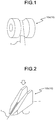
- an oiling nozzle 10b illustrated in FIG. 2 is used to apply oil to the fiber 1.
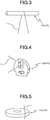
- a rod guide 10c illustrated in FIG. 3 is used to bundle or separate the fibers 1.
- a traverse guide 10d illustrated in FIG. 4 is used as a guide to wind the fiber 1 around the outer circumference of a cylindrical package.
- a friction disk 10e illustrated in FIG. 5 is used to twist the fiber 1.
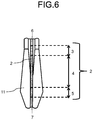
- FIG. 6 is a top view (the view in the direction of the arrow that is white with the black outline in FIG. 2 ) of the oiling nozzle 10b illustrated in FIG. 2 .
- the fiber guide is denoted by the reference numeral "10", except for the case where the specific fiber guide is described.
- the fiber guide 10 includes a base 11 and a fiber contact surface 2 that is brought into contact with the fiber 1 in at least part of the base 11.
- the fiber contact surface 2 is a surface of the fiber guide 10 that is brought into contact with the fiber 1 and, to discriminate it from the base 11, the fiber contact surface 2 is in the depth up to 0.2 mm from the surface that is brought into contact with the fiber 1.
- the fiber contact surface 2 is illustrated in color so as to be distinguished.
- the inlet side and the outlet side for the fiber 1 need to be clearly distinguished on the fiber contact surface 2, and the fiber contact surface 2 includes an inlet portion 3, an intermediate portion 4, and an outlet portion 5.
- the fiber guide including the fiber contact surface 2 including the inlet portion 3, the intermediate portion 4, and the outlet portion 5 is, for example, the oiling nozzle 10b illustrated in FIG. 2 .
- the fiber contact surface 2 of the above-described oiling nozzle 10b includes a pair of a first end 6 and a second end 7 in a delivering direction of the fiber 1.
- the first end 6 is the portion of the fiber contact surface 2 with which the fiber 1 is first brought into contact at the inlet side of the fiber 1
- the second end 7 is the portion of the fiber contact surface 2 with which the fiber 1 is in contact up to the end at the outlet side of the fiber 1.
- the inlet portion 3 refers to, when the entire length of the fiber contact surface 2 is from the first end 6 to the second end 7, the portion of 1/5 of the entire length from the first end 6.
- the outlet portion 5 refers to the portion of 1/5 of the entire length from the second end 7.
- the portion of the fiber contact surface 2 between the inlet portion 3 and the outlet portion 5 is the intermediate portion 4.
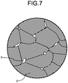
- the fiber contact surface 2 of the fiber guide 10 includes an aluminum oxide ceramic and, as illustrated in FIG. 7 , includes a zirconium silicate phase 8 between aluminum oxide crystals 9.
- aluminum oxide ceramic out of 100 mass-% of all the components included in the aluminum oxide ceramic, aluminum oxide occupies 80 or more mass-%.
- the material of the fiber contact surface 2 may be confirmed in the following method. First of all, measurement is conducted on the fiber contact surface 2 by using an X-ray diffraction device (XRD), and identification is executed by using the JCPDS card based on the obtained value of 2 ⁇ (2 ⁇ is a diffraction angle). Subsequently, quantitative analysis is conducted on components contained in the fiber contact surface 2 by using a fluorescence X-ray analysis device (XRF). Subsequently, an aluminum oxide ceramic is determined when the presence of aluminum oxide is confirmed during the identification by the above-described XRD and the content of aluminum oxide (Al 2 O 3 ), converted from the content of aluminum (Al) measured by the above-described XRF, is 80 or more mass-%.
- XRD X-ray diffraction device
- XRF fluorescence X-ray analysis device
- the zirconium silicate phase 8 has a low friction coefficient as compared with the aluminum oxide crystal 9.
- the fiber contact surface 2 has a low friction coefficient.
- the presence or absence of the zirconium silicate phase 8 in the fiber contact surface 2 may be determined in the following method.
- elemental mapping is executed on the area that is recognized as a phase present between the aluminum oxide crystals 9. If zirconium, silicon, and oxygen are simultaneously detected during the elemental mapping, it is determined that the fiber guide 10 according to the present disclosure includes the zirconium silicate phase 8. As the aluminum oxide layer 9 is present under the zirconium silicate phase 8, aluminum may be detected even when no aluminum oxide is included between the aluminum oxide crystals 9.
- EPMA Electron Probe Micro Analyzer
- FIG. 7 schematically illustrates a state of the fiber contact surface 2 observed by a Scanning Electron Microscope (SEM), or the like.
- SEM Scanning Electron Microscope
- the color relation in FIG. 7 is based on an SEM image (picture); the zirconium silicate phase 8 exhibits a white-based color, and the aluminum oxide crystal 9 exhibits a black-based color, whereby the zirconium silicate phase 8 and the aluminum oxide crystal 9 may be visually discriminated.
- the base 11 and the fiber contact surface 2 include an integrated aluminum oxide ceramic, and the percentage of the area occupied by the zirconium silicate phase 8 in the fiber contact surface 2 may be higher than the percentage of the area occupied by the zirconium silicate phase 8 inside the base 11.
- the inside of the base 11 refers to a portion in the depth of 0.2 or more mm from the surface of the base 11.
- the material of the base 11 may be confirmed in the same method as the above-described method for confirming the material of the fiber contact surface 2.
- the heat conductivity of the zirconium silicate phase 8 is approximately 3 to 8 W/m ⁇ K. Conversely, the heat conductivity of the aluminum oxide crystal 9 is approximately 15 to 40 W/m ⁇ K. Therefore, when the above-described configuration is satisfied, the fiber contact surface 2 having a higher percentage of the area occupied by the zirconium silicate phase 8 as compared with the base 11 has a lower heat conductivity than that of the inside of the base 11; thus, the friction heat generated in the fiber contact surface 2 during the delivery of the fiber 1 is diffused into the inside of the base 11 having a higher heat conductivity so that an increase in the temperature of the fiber contact surface 2 may be suppressed. Thus, in the fiber guide 10 according to the present disclosure, damage such as scratch or looseness are unlikely to occur in the fiber 1 even though the fiber 1 is guided for a long period of time. In other words, the friction coefficient of the fiber contact surface 2 may be maintained.
- the percentage of the area occupied by the zirconium silicate phase 8 in the fiber contact surface 2 may be higher than the percentage of the area occupied by the zirconium silicate phase 8 inside the base 11 by 0.2 or more area-%.
- the friction coefficient of the fiber contact surface 2 may be further maintained in the fiber guide 10 according to the present disclosure even though the fiber 1 is guided for a long time of period.
- the percentage of the area occupied by the zirconium silicate phase 8 in the fiber contact surface 2 may be, for example, 0.2 or more area-% and 1.8 or less area-%.
- the percentage of the area occupied by the zirconium silicate phase 8 inside the base 11 is, for example, 0.1 or less area-% and may be 0 area-%, in which the zirconium silicate phase 8 is not present.
- the percentage of the area occupied by the zirconium silicate phase 8 in the fiber contact surface 2 and inside the base 11 may be calculated in the following method.
- BEI backscattered electron image
- the zirconium silicate phase 8 exhibits a white-based color as described above, image analysis is performed on the picture by applying a particle analysis technique of the image analysis software "A-zo Kun” (registered trademark, manufactured by Asahi Kasei Engineering Corporation; when the image analysis software "A-zo Kun” is described below, it indicates the image analysis software manufactured by Asahi Kasei Engineering Corporation) so that the percentage of the area occupied by the zirconium silicate phase 8 may be obtained.
- A-zo Kun registered trademark, manufactured by Asahi Kasei Engineering Corporation
- the percentage of the area occupied by the zirconium silicate phase 8 in the fiber contact surface 2 is the average value of the image analysis on six or more pictures at different areas of the fiber contact surface 2 captured at 1000 to 3000 magnification.
- the contact surface 2 includes the inlet portion 3, the intermediate portion 4, and the outlet portion 5, the image analysis is conducted on two pictures at each of the different areas in the inlet portion 3, the intermediate portion 4, and the outlet portion 5, and the average value may be the percentage of the area occupied by the zirconium silicate phase 8 in the fiber contact surface 2.
- the percentage of the area occupied by the zirconium silicate phase 8 inside the base 11 is the average value of the image analysis on six or more pictures at different areas inside the base 11 captured at 1000 to 3000 magnification.
- Examples of the analysis conditions of "A-zo Kun” include, but are not limited to, "bright” for the brightness of a crystal particle, “manual” for the method for binarization, “present” for shading, etc., and a threshold may be set so as to clearly distinguish between the zirconium silicate phase 8 and the aluminum oxide crystal 9.
- the percentage of the area occupied by the zirconium silicate phase 8 in the inlet portion 3 may be higher than the percentage of the area occupied by the zirconium silicate phase 8 in the intermediate portion 4.
- the inlet portion 3 which is a portion where the fiber 1 is most likely to be damaged, may have low frictional resistance.
- the percentage of the area occupied by the zirconium silicate phase 8 in the inlet portion 3 included in the fiber contact surface 2 may be 0.3 or more area-% and 2.5 or less area-%.
- the percentage of the area occupied by the zirconium silicate phase 8 in the inlet portion 3 and the intermediate portion 4 may be calculated by the particle analysis of the image analysis software "A-zo Kun" in the same manner as the above-described method for calculating the percentage of the area occupied by the zirconium silicate phase in the fiber contact surface 2 and inside the base 11.
- the percentage of the area occupied by the zirconium silicate phase 8 in the inlet portion 3 is the average value of the image analysis on two or more pictures at different areas of the inlet portion 3 captured at 1000 to 3000 magnification.
- the percentage of the area occupied by the zirconium silicate phase 8 in the intermediate portion 4 is the average value of the image analysis on two or more pictures at different areas of the intermediate portion 4 captured at 1000 to 3000 magnification.
- the average value of the equivalent circle diameter of the zirconium silicate phase 8 in the fiber contact surface 2 may be 0.6 or more ⁇ m and 3.2 or less ⁇ m.
- the equivalent circle diameter refers to the diameter of the circle when the zirconium silicate phase 8 is converted into the circle having the same size. When this configuration is satisfied, the zirconium silicate phase 8 is unlikely to be removed from the fiber contact surface 2 so that the friction coefficient of the fiber contact surface 2 may be further maintained.
- the average value of the equivalent circle diameter of the aluminum oxide crystal 9 is, for example, 10 or more ⁇ m and 25 or less ⁇ m.
- the average value of the equivalent circle diameter of each of the zirconium silicate phase 8 and the aluminum oxide crystal 9 may be calculated in the same method as the above-described method for calculating the percentage of the area occupied by the zirconium silicate phase in the fiber contact surface 2.
- a sliding testing device illustrated in FIG. 8 is a device that includes a roller R1, a roller R2, the fiber guide 10, a roller R3, and a roller R4 so as to guide the fiber 1 in this order.
- the roller R2 and the roller R3 are coupled to tension detectors (not illustrated).
- the friction coefficient changes in accordance with a testing condition, such as the type of the fiber 1, the form of the fiber 1, the delivering speed of the fiber 1, the tensional force of the fiber 1, or ⁇ . For this reason, the comparison between friction coefficients needs to be performed under the same testing condition.
- the oiling nozzle 10b is described as an example.
- the base 11 and the fiber contact surface 2 include an integrated aluminum oxide ceramic.
- zirconium silicate (ZrSiO 4 ) powders may be doped when a slurry is produced.
- spray drying is conducted by using a spray drier to produce granular powders.
- the granular powders, thermoplastic resin, wax, and the like are put into a kneader and mixed while heated to obtain a paste.
- the obtained paste is put into a pelletizer to obtain pellets that are the material for injection molding (injection molding).
- the obtained pellets are put into an injection molding machine (injection molding machine) for injection molding so as to obtain a compact shaped like an oiling nozzle.
- injection molding machine injection molding machine
- a mold for obtaining an oiling nozzle shape may be manufactured according to a typical injection molding technique and may be placed in the injection molding machine for injection molding.
- the obtained compact is sintered in the air atmosphere at the highest temperature of 1500 or more °C and 1600 or less °C and in the retention time of two or more hours and five or less hours at the highest temperature to obtain a sinter.
- the sintering condition such as the highest temperature or the retention time, changes in accordance with the shape and the size of a product, they may be adjusted as appropriate.
- the sinter, abrasive media, and water are put into a wet barrel finishing machine, and barrel finishing is performed.
- zirconium silicate powders have been mixed with water; therefore, when the media collides with the sinter during barrel finishing, the zirconium silicate powders enter the gap between the aluminum oxide crystals 9 so as to adhere to the surface of the sinter as the zirconium silicate phase 8.
- the sinter is cleaned and dried to obtain the oiling nozzle 10b according to the present disclosure.
- the percentage of the area occupied by the zirconium silicate phase 8 in the fiber contact surface 2 and inside the base 11 may be controlled to have any value by adjusting the amount of zirconium silicate powders doped to produce a slurry, the amount of zirconium silicate powders mixed with water during barrel finishing, and the time period of the barrel finishing.
- the percentage of the area occupied by the zirconium silicate phase 8 in the inlet portion 3 and the intermediate portion 4 of the fiber contact surface 2 may be controlled to have any value by adjusting the amount of zirconium silicate powders mixed with water during barrel finishing and the time period of the barrel finishing and by executing barrel finishing while masking parts of the inlet portion 3 and the intermediate portion 4 of the fiber contact surface 2.
- the average particle diameter of the zirconium silicate powder used may be adjusted so that the average value of the equivalent circle diameter of the zirconium silicate phase 8 in the fiber contact surface 2 becomes 0.6 or more ⁇ m and 3.2 or less ⁇ m.
- Oiling nozzles were manufactured, which were different depending on the presence or absence of a zirconium silicate phase in a fiber contact surface. A sliding test was conducted on the oiling nozzles to compare the friction coefficients of fiber contact surfaces.
- aluminum oxide powders, titanium oxide (TiO 2 ) powders and magnesium carbonate (MgCO 3 ) powders as sintering agents were prepared.
- the powders were weighted and mixed such that the aluminum oxide powders were 98.4 mass-%, the titanium oxide powders were 1 mass-%, and the magnesium carbonate powders were 0.6 mass-% in terms of magnesium oxide (MgO).
- they were put into a mill together with water, which was a solvent, and a ball to be ground so as to produce a slurry.
- the granular powders, thermoplastic resin, and wax were additionally put into a kneader and mixed while heated to obtain a paste.
- the obtained paste was put into a pelletizer to obtain pellets that were the material for injection molding.
- the obtained pellets were put into an injection molding machine for injection molding so as to obtain a compact shaped like an oiling nozzle.
- the compact was sintered in the air atmosphere at the highest temperature of 1550 °C and in the retention time of three hours at the highest temperature to obtain a sinter.
- the sinter, abrasive media, and water were put into a wet barrel finishing machine and were subjected to barrel finishing for two hours.
- zirconium silicate powders having an average particle diameter of 3.5 ⁇ m were mixed with water such that the amount to be doped was 0.015 mass-% with respect to 100 mass-% of the total amount of water and zirconium silicate powders.
- barrel finishing was conducted by using water that was not mixed with zirconium silicate powders to obtain a sample No. 2.
- each sample was set in the sliding testing device illustrated in FIG. 8 and was subjected to a sliding test to obtain the friction coefficient of each sample.
- the measurement conditions were as follows:
- Table 1 illustrates the results.
- Table 1 SAMPLE NO. PRESENCE OR ABSENCE OF ZIRCONIUM SILICATE PHASE FRICTION COEFFICIENT ⁇ 1 PRESENT 0.36 2 ABSENT 0.45
- the sample No. 1 had a low friction coefficient of 0.36 as compared with the sample No. 2. This indicates that, when the fiber contact surface includes the zirconium silicate phase, the fiber contact surface has a low friction coefficient.
- oiling nozzles having different percentages of the area occupied by the zirconium silicate phase in the fiber contact surface and inside the base were produced.
- a sliding test was conducted on the oiling nozzles to compare the friction coefficients of the fiber contact surfaces.
- the production method was the same as the method for producing the sample No. 1 according to the first embodiment except that the amount of zirconium silicate powders illustrated in Table 2 was doped to produce a slurry and the amount of zirconium silicate powders illustrated in Table 2 was doped and mixed with water during barrel finishing, and a sample No. 5 was the same as the sample No. 1 according to the first embodiment.
- the slurry was doped with zirconium silicate powders
- the amount of aluminum oxide powders to be doped was reduced by the amount of zirconium silicate powders doped.
- the percentage of the area occupied by the zirconium silicate phase in the fiber contact surface and inside the base of each sample was calculated in the following method.
- backscattered electron image pictures of the fiber contact surface and the inside of the base were taken by using the SEM.
- the image analysis was performed on the picture by applying a particle analysis technique of the image analysis software "A-zo Kun" so that the percentage of the area occupied by the zirconium silicate phase was obtained.
- the percentage of the area occupied by the zirconium silicate phase in the fiber contact surface was the average value of the image analysis on two pictures at different areas in the inlet portion, the intermediate portion, and the outlet portion of the fiber contact surface captured at 2000 magnification.
- the percentage of the area occupied by the zirconium silicate phase inside the base was the average value of the image analysis on six pictures at different areas of the inside captured at 2000 magnification.
- the sliding test was performed in the same manner as in the first embodiment except that the start time of the measurement of a friction coefficient was 20 minutes after the start of the sliding test, and the friction coefficient of the fiber contact surface of each sample was obtained. Table 2 illustrates the results. Table 2 SAMPLE NO.
- ZIRCONIUM SILICATE POWDERS (MASS-%) PERCENTAGE OF AREA OCCUPIED BY ZIRCONIUM SILICATE PHASE FRICTION COEFFICIENT ⁇ SLURRY BARREL FINISHING FIBER CONTACT SURFACE INSIDE DIFFERENCE (FIBER CONTACT SURFACE-IN SIDE) 3 0.2 0 0.2 0.2 0 0.4 4 0 0.01 0.13 0 0.13 0.38 5 0 0.015 0.2 0 0.2 0.36 6 0 0.04 0.6 0 0.6 0.35 7 0 0.13 1.8 0 1.8 0.34 8 0.2 0.13 2.0 0.2 1.8 0.34
- samples No. 4 to 8 had a low friction coefficient of 0.38 or less in the fiber contact surface, as compared with the sample No. 3. This indicates that, when the percentage of the area occupied by the zirconium silicate phase in the fiber contact surface is higher than the percentage of the area occupied by the zirconium silicate phase inside the base, the friction coefficient of the fiber contact surface may be maintained.
- the samples No. 5 to 8 had a low friction coefficient of 0.36 or less in the fiber contact surface. This indicates that, when the percentage of the area occupied by the zirconium silicate phase in the fiber contact surface is higher than the percentage of the area occupied by the zirconium silicate phase inside the base by 0.2 or more area-%, the friction coefficient of the fiber contact surface may be further maintained.
- oiling nozzles having different percentages of the area occupied by the zirconium silicate phase in the inlet portion and the intermediate portion of the fiber contact surface were produced.
- a sliding test was performed on the oiling nozzles to compare the friction coefficients of the fiber contact surfaces.
- the production method was the same as the method for producing the sample No. 1 according to the first embodiment except that the amount of zirconium silicate powders doped and mixed with water during barrel finishing was adjusted and parts of the inlet portion and the intermediate portion in the fiber contact surface were masked so that the percentage of the area occupied by the zirconium silicate phase became the value illustrated in Table 3, and a sample No. 9 was the same sample as the sample No. 1 according to the first embodiment.
- Table 3 illustrates the results.
- Table 3 SAMPLE NO. PERCENTAGE OF AREA OCCUPIED BY ZIRCONIUM SILICATE PHASE (AREA-%) FRICTION COEFFICIENT ⁇ INLET PORTION INTERMEDIATE PORTION 9 0.2 0.2 0.36 10 0.1 0.2 0.37 11 0.2 0.1 0.32 12 0.3 0.1 0.29 13 1 0.1 0.28 14 2.5 0.1 0.29 15 3 0.1 0.32
- the samples No. 11 to 15 have a low friction coefficient of 0.32 or less in the fiber contact surface, as compared with the samples No. 9, 10. This indicates that, when the percentage of the area occupied by the zirconium silicate phase in the inlet portion is higher than the percentage of the area occupied by the zirconium silicate phase in the intermediate portion, the friction coefficient of the fiber contact surface may be lower.
- the samples No. 12 to 14 have a low friction coefficient of 0.29 or less in the fiber contact surface. This indicates that, when the percentage of the area occupied by the zirconium silicate phase in the inlet portion is 0.3 or more area-% and 2.5 or less area-%, the friction coefficient of the fiber contact surface may be lower.
- oiling nozzles having different average values of the equivalent circle diameter of the zirconium silicate phase in the fiber contact surface were produced.
- a sliding test was performed on the oiling nozzles to compare the friction coefficients of the fiber contact surfaces.
- the production method was the same as the method for producing the sample No. 6 according to the second embodiment except that the zirconium silicate powder having the average particle diameter illustrated in Table 4 was used during barrel finishing and the barrel time period illustrated in Table 4 was applied, and a sample No. 20 was the same sample as the sample No. 6 according to the second embodiment.
- the barrel time period for each sample was changed so that the percentage of the area occupied by the zirconium silicate phase in the fiber contact surface of each sample became 0.6 area-%.
- the average value of the equivalent circle diameter of the zirconium silicate phase in the fiber contact surface of each sample was calculated in the same method as the method for calculating the percentage of the area occupied by the zirconium silicate phase in the fiber contact surface according to the second embodiment.
- Table 4 illustrates the results.
- Table 4 SAMPLE NO. AVERAGE PARTICLE DIAMETER ( ⁇ m) OF ZIRCONIUM SILICATE POWDER BARREL TIME PERIOD (HOUR) AVERAGE VALUE ( ⁇ m) OF EQUIVALENT CIRCLE DIAMETER OF ZIRCONIUM SILICATE PHASE FRICTION COEFFICIENT ⁇ 16 0.4 6 0.4 0.35 17 0.4 5 0.6 0.29 18 1.8 4 1.8 0.27 19 3.2 3 3.2 0.29 20 3.5 2 3.5 0.35
- samples No. 17 to 19 have a low friction coefficient of 0.29 or less in the fiber contact surface, as compared with the samples No. 16, 20. This indicates that, when the average value of the equivalent circle diameter of the zirconium silicate phase in the fiber contact surface is 0.6 or more ⁇ m and 3.2 or less ⁇ m, the friction coefficient of the fiber contact surface may be further maintained.
Landscapes
- Engineering & Computer Science (AREA)
- Mechanical Engineering (AREA)
- Textile Engineering (AREA)
- Guides For Winding Or Rewinding, Or Guides For Filamentary Materials (AREA)
- Spinning Methods And Devices For Manufacturing Artificial Fibers (AREA)
- Inorganic Fibers (AREA)
- Compositions Of Oxide Ceramics (AREA)
Abstract
Description
- The present disclosure relates to a fiber guide. Background
- To guide a fiber, fiber guides having various shapes, which are called a roller guide, an oiling nozzle, a rod guide, a traverse guide, or a friction disk, are attached to a fiber machine while in use. As for a surface (hereinafter referred to as a fiber contact surface) of a fiber guide that is brought into contact with a fiber, there is a demand to prevent the occurrence of damage, such as scratch or looseness, to a fiber. There is also a demand for low manufacturing costs of fiber guides.
- For these reasons, aluminum oxide ceramics, which are superior in abrasion resistance regardless of low costs, are often used as the material of a fiber guide.
- For example,
Patent Literature 1 discloses a guide that includes aluminum oxide and has a Vickers hardness HV of 1900 or more. - Patent Literature 1: Japanese Laid-open Patent Publication No.
2003-213522 -
-
FIG. 1 is a perspective view of a roller guide to illustrate an example of a fiber guide according to the present disclosure. -
FIG. 2 is a perspective view of an oiling nozzle to illustrate an example of the fiber guide according to the present disclosure. -
FIG. 3 is a perspective view of a rod guide to illustrate an example of the fiber guide according to the present disclosure. -
FIG. 4 is a perspective view of a traverse guide to illustrate an example of the fiber guide according to the present disclosure. -
FIG. 5 is a perspective view of a friction disk to illustrate an example of the fiber guide according to the present disclosure. -
FIG. 6 is a top view of the oiling nozzle illustrated inFIG. 2 . -
FIG. 7 is a schematic diagram that illustrates an example of a surface of the fiber guide according to the present disclosure. -
FIG. 8 is a schematic view of a sliding testing device. - In recent years, there has been an extreme increase in the delivering speed of fibers up to 1000 to 10000 m/minute to improve the productive efficiency of fibers. Therefore, there is a demand for a fiber guide having a fiber contact surface with a low friction coefficient, which is unlikely to give damage to fibers regardless of an increase in the delivering speed of fibers.
- With the fiber guide according to the present disclosure, a fiber contact surface with a low friction coefficient may reduce the occurrence of damage to fibers while the fibers are guided. The fiber guide according to the present disclosure is described below in detail with reference to drawings.
- First, the typical types of fiber guides are described with reference to
FIGS. 1 to 5 . First of all, aroller guide 10a illustrated inFIG. 1 guides afiber 1 at a U-shaped groove portion while rotating. Then, anoiling nozzle 10b illustrated inFIG. 2 is used to apply oil to thefiber 1. Then, arod guide 10c illustrated inFIG. 3 is used to bundle or separate thefibers 1. Then, atraverse guide 10d illustrated inFIG. 4 is used as a guide to wind thefiber 1 around the outer circumference of a cylindrical package. Afriction disk 10e illustrated inFIG. 5 is used to twist thefiber 1. -
FIG. 6 is a top view (the view in the direction of the arrow that is white with the black outline inFIG. 2 ) of theoiling nozzle 10b illustrated inFIG. 2 . In the following description, the fiber guide is denoted by the reference numeral "10", except for the case where the specific fiber guide is described. - As illustrated in
FIG. 6 , thefiber guide 10 according to the present disclosure includes abase 11 and afiber contact surface 2 that is brought into contact with thefiber 1 in at least part of thebase 11. Thefiber contact surface 2 is a surface of thefiber guide 10 that is brought into contact with thefiber 1 and, to discriminate it from thebase 11, thefiber contact surface 2 is in the depth up to 0.2 mm from the surface that is brought into contact with thefiber 1. InFIG. 6 , thefiber contact surface 2 is illustrated in color so as to be distinguished. The inlet side and the outlet side for thefiber 1 need to be clearly distinguished on thefiber contact surface 2, and thefiber contact surface 2 includes aninlet portion 3, anintermediate portion 4, and anoutlet portion 5. The fiber guide including thefiber contact surface 2 including theinlet portion 3, theintermediate portion 4, and theoutlet portion 5 is, for example, theoiling nozzle 10b illustrated inFIG. 2 . Thefiber contact surface 2 of the above-describedoiling nozzle 10b includes a pair of afirst end 6 and asecond end 7 in a delivering direction of thefiber 1. Thefirst end 6 is the portion of thefiber contact surface 2 with which thefiber 1 is first brought into contact at the inlet side of thefiber 1, and thesecond end 7 is the portion of thefiber contact surface 2 with which thefiber 1 is in contact up to the end at the outlet side of thefiber 1. Theinlet portion 3 refers to, when the entire length of thefiber contact surface 2 is from thefirst end 6 to thesecond end 7, the portion of 1/5 of the entire length from thefirst end 6. Conversely, theoutlet portion 5 refers to the portion of 1/5 of the entire length from thesecond end 7. The portion of thefiber contact surface 2 between theinlet portion 3 and theoutlet portion 5 is theintermediate portion 4. - The
fiber contact surface 2 of thefiber guide 10 according to the present disclosure includes an aluminum oxide ceramic and, as illustrated inFIG. 7 , includes azirconium silicate phase 8 betweenaluminum oxide crystals 9. - In the aluminum oxide ceramic, out of 100 mass-% of all the components included in the aluminum oxide ceramic, aluminum oxide occupies 80 or more mass-%.
- The material of the
fiber contact surface 2 may be confirmed in the following method. First of all, measurement is conducted on thefiber contact surface 2 by using an X-ray diffraction device (XRD), and identification is executed by using the JCPDS card based on the obtained value of 2θ (2θ is a diffraction angle). Subsequently, quantitative analysis is conducted on components contained in thefiber contact surface 2 by using a fluorescence X-ray analysis device (XRF). Subsequently, an aluminum oxide ceramic is determined when the presence of aluminum oxide is confirmed during the identification by the above-described XRD and the content of aluminum oxide (Al2O3), converted from the content of aluminum (Al) measured by the above-described XRF, is 80 or more mass-%. - The
zirconium silicate phase 8 has a low friction coefficient as compared with thealuminum oxide crystal 9. In thefiber guide 10 according to the present disclosure, as thezirconium silicate phase 8 is provided between thealuminum oxide crystals 9, thefiber contact surface 2 has a low friction coefficient. - The presence or absence of the
zirconium silicate phase 8 in thefiber contact surface 2 may be determined in the following method. - First of all, by using an Electron Probe Micro Analyzer (EPMA), elemental mapping is executed on the area that is recognized as a phase present between the
aluminum oxide crystals 9. If zirconium, silicon, and oxygen are simultaneously detected during the elemental mapping, it is determined that thefiber guide 10 according to the present disclosure includes thezirconium silicate phase 8. As thealuminum oxide layer 9 is present under thezirconium silicate phase 8, aluminum may be detected even when no aluminum oxide is included between thealuminum oxide crystals 9. -
FIG. 7 schematically illustrates a state of thefiber contact surface 2 observed by a Scanning Electron Microscope (SEM), or the like. The color relation inFIG. 7 is based on an SEM image (picture); thezirconium silicate phase 8 exhibits a white-based color, and thealuminum oxide crystal 9 exhibits a black-based color, whereby thezirconium silicate phase 8 and thealuminum oxide crystal 9 may be visually discriminated. - In the
fiber guide 10 according to the present disclosure, thebase 11 and thefiber contact surface 2 include an integrated aluminum oxide ceramic, and the percentage of the area occupied by thezirconium silicate phase 8 in thefiber contact surface 2 may be higher than the percentage of the area occupied by thezirconium silicate phase 8 inside thebase 11. The inside of thebase 11 refers to a portion in the depth of 0.2 or more mm from the surface of thebase 11. The material of thebase 11 may be confirmed in the same method as the above-described method for confirming the material of thefiber contact surface 2. - The heat conductivity of the
zirconium silicate phase 8 is approximately 3 to 8 W/m·K. Conversely, the heat conductivity of thealuminum oxide crystal 9 is approximately 15 to 40 W/m·K. Therefore, when the above-described configuration is satisfied, thefiber contact surface 2 having a higher percentage of the area occupied by thezirconium silicate phase 8 as compared with thebase 11 has a lower heat conductivity than that of the inside of thebase 11; thus, the friction heat generated in thefiber contact surface 2 during the delivery of thefiber 1 is diffused into the inside of thebase 11 having a higher heat conductivity so that an increase in the temperature of thefiber contact surface 2 may be suppressed. Thus, in thefiber guide 10 according to the present disclosure, damage such as scratch or looseness are unlikely to occur in thefiber 1 even though thefiber 1 is guided for a long period of time. In other words, the friction coefficient of thefiber contact surface 2 may be maintained. - In the
fiber guide 10 according to the present disclosure, the percentage of the area occupied by thezirconium silicate phase 8 in thefiber contact surface 2 may be higher than the percentage of the area occupied by thezirconium silicate phase 8 inside thebase 11 by 0.2 or more area-%. When this configuration is satisfied, the friction coefficient of thefiber contact surface 2 may be further maintained in thefiber guide 10 according to the present disclosure even though thefiber 1 is guided for a long time of period. - The percentage of the area occupied by the
zirconium silicate phase 8 in thefiber contact surface 2 may be, for example, 0.2 or more area-% and 1.8 or less area-%. The percentage of the area occupied by thezirconium silicate phase 8 inside thebase 11 is, for example, 0.1 or less area-% and may be 0 area-%, in which thezirconium silicate phase 8 is not present. - The percentage of the area occupied by the
zirconium silicate phase 8 in thefiber contact surface 2 and inside thebase 11 may be calculated in the following method. First of all, backscattered electron image (BEI) pictures (hereafter simply referred to as pictures) of thefiber contact surface 2 and the inside of the base 11 are taken by using the SEM. As thezirconium silicate phase 8 exhibits a white-based color as described above, image analysis is performed on the picture by applying a particle analysis technique of the image analysis software "A-zo Kun" (registered trademark, manufactured by Asahi Kasei Engineering Corporation; when the image analysis software "A-zo Kun" is described below, it indicates the image analysis software manufactured by Asahi Kasei Engineering Corporation) so that the percentage of the area occupied by thezirconium silicate phase 8 may be obtained. - The percentage of the area occupied by the
zirconium silicate phase 8 in thefiber contact surface 2 is the average value of the image analysis on six or more pictures at different areas of thefiber contact surface 2 captured at 1000 to 3000 magnification. As thecontact surface 2 includes theinlet portion 3, theintermediate portion 4, and theoutlet portion 5, the image analysis is conducted on two pictures at each of the different areas in theinlet portion 3, theintermediate portion 4, and theoutlet portion 5, and the average value may be the percentage of the area occupied by thezirconium silicate phase 8 in thefiber contact surface 2. - The percentage of the area occupied by the
zirconium silicate phase 8 inside thebase 11 is the average value of the image analysis on six or more pictures at different areas inside the base 11 captured at 1000 to 3000 magnification. - Examples of the analysis conditions of "A-zo Kun" include, but are not limited to, "bright" for the brightness of a crystal particle, "manual" for the method for binarization, "present" for shading, etc., and a threshold may be set so as to clearly distinguish between the
zirconium silicate phase 8 and thealuminum oxide crystal 9. - On the
fiber contact surface 2 of thefiber guide 10 according to the present disclosure, the percentage of the area occupied by thezirconium silicate phase 8 in theinlet portion 3 may be higher than the percentage of the area occupied by thezirconium silicate phase 8 in theintermediate portion 4. When this configuration is satisfied, theinlet portion 3, which is a portion where thefiber 1 is most likely to be damaged, may have low frictional resistance. In thefiber guide 10 according to the present disclosure, the percentage of the area occupied by thezirconium silicate phase 8 in theinlet portion 3 included in thefiber contact surface 2 may be 0.3 or more area-% and 2.5 or less area-%. - The percentage of the area occupied by the
zirconium silicate phase 8 in theinlet portion 3 and theintermediate portion 4 may be calculated by the particle analysis of the image analysis software "A-zo Kun" in the same manner as the above-described method for calculating the percentage of the area occupied by the zirconium silicate phase in thefiber contact surface 2 and inside thebase 11. Specifically, the percentage of the area occupied by thezirconium silicate phase 8 in theinlet portion 3 is the average value of the image analysis on two or more pictures at different areas of theinlet portion 3 captured at 1000 to 3000 magnification. The percentage of the area occupied by thezirconium silicate phase 8 in theintermediate portion 4 is the average value of the image analysis on two or more pictures at different areas of theintermediate portion 4 captured at 1000 to 3000 magnification. - In the
fiber guide 10 according to the present disclosure, the average value of the equivalent circle diameter of thezirconium silicate phase 8 in thefiber contact surface 2 may be 0.6 or more µm and 3.2 or less µm. The equivalent circle diameter refers to the diameter of the circle when thezirconium silicate phase 8 is converted into the circle having the same size. When this configuration is satisfied, thezirconium silicate phase 8 is unlikely to be removed from thefiber contact surface 2 so that the friction coefficient of thefiber contact surface 2 may be further maintained. - The average value of the equivalent circle diameter of the
aluminum oxide crystal 9 is, for example, 10 or more µm and 25 or less µm. - The average value of the equivalent circle diameter of each of the
zirconium silicate phase 8 and thealuminum oxide crystal 9 may be calculated in the same method as the above-described method for calculating the percentage of the area occupied by the zirconium silicate phase in thefiber contact surface 2. - Then, the method for measuring the friction coefficient of the
fiber contact surface 2 is described with reference toFIG. 8 . A sliding testing device illustrated inFIG. 8 is a device that includes a roller R1, a roller R2, thefiber guide 10, a roller R3, and a roller R4 so as to guide thefiber 1 in this order. The roller R2 and the roller R3 are coupled to tension detectors (not illustrated). - Calculation is performed according to Amonton's Law equation (µ={lnT2-T1)}/θ) by using the measured value of tension T1 detected by the tension detector of the roller R2 and the measured value of tension T2 detected by the tension detector of the roller R3 while the
fiber 1 is guided by using the sliding testing device so as to obtain a friction coefficient (µ). - The friction coefficient changes in accordance with a testing condition, such as the type of the
fiber 1, the form of thefiber 1, the delivering speed of thefiber 1, the tensional force of thefiber 1, or θ. For this reason, the comparison between friction coefficients needs to be performed under the same testing condition. - Then, an example of the method for producing the
fiber guide 10 according to the present disclosure is described. Among the fiber guides 10, the oilingnozzle 10b is described as an example. In an example of the case described, thebase 11 and thefiber contact surface 2 include an integrated aluminum oxide ceramic. - First of all, aluminum oxide (Al2O3) powders, a sintering agent, and a solvent are put into a mill together with a ball and is smashed to have predetermined granularity so as to produce a slurry. To obtain the
fiber guide 10 having thezirconium silicate phase 8 inside thebase 11, zirconium silicate (ZrSiO4) powders may be doped when a slurry is produced. - Subsequently, after the obtained slurry is doped with a binder, spray drying is conducted by using a spray drier to produce granular powders.
- Subsequently, the granular powders, thermoplastic resin, wax, and the like, are put into a kneader and mixed while heated to obtain a paste. The obtained paste is put into a pelletizer to obtain pellets that are the material for injection molding (injection molding). Subsequently, the obtained pellets are put into an injection molding machine (injection molding machine) for injection molding so as to obtain a compact shaped like an oiling nozzle. To obtain a compact shaped like an oiling nozzle, a mold for obtaining an oiling nozzle shape may be manufactured according to a typical injection molding technique and may be placed in the injection molding machine for injection molding.
- Subsequently, the obtained compact is sintered in the air atmosphere at the highest temperature of 1500 or more °C and 1600 or less °C and in the retention time of two or more hours and five or less hours at the highest temperature to obtain a sinter. As the sintering condition, such as the highest temperature or the retention time, changes in accordance with the shape and the size of a product, they may be adjusted as appropriate.
- Subsequently, the sinter, abrasive media, and water are put into a wet barrel finishing machine, and barrel finishing is performed. At this point, zirconium silicate powders have been mixed with water; therefore, when the media collides with the sinter during barrel finishing, the zirconium silicate powders enter the gap between the
aluminum oxide crystals 9 so as to adhere to the surface of the sinter as thezirconium silicate phase 8. - After the barrel finishing, the sinter is cleaned and dried to obtain the oiling
nozzle 10b according to the present disclosure. - The percentage of the area occupied by the
zirconium silicate phase 8 in thefiber contact surface 2 and inside thebase 11 may be controlled to have any value by adjusting the amount of zirconium silicate powders doped to produce a slurry, the amount of zirconium silicate powders mixed with water during barrel finishing, and the time period of the barrel finishing. - The percentage of the area occupied by the
zirconium silicate phase 8 in theinlet portion 3 and theintermediate portion 4 of thefiber contact surface 2 may be controlled to have any value by adjusting the amount of zirconium silicate powders mixed with water during barrel finishing and the time period of the barrel finishing and by executing barrel finishing while masking parts of theinlet portion 3 and theintermediate portion 4 of thefiber contact surface 2. - The average particle diameter of the zirconium silicate powder used may be adjusted so that the average value of the equivalent circle diameter of the
zirconium silicate phase 8 in thefiber contact surface 2 becomes 0.6 or more µm and 3.2 or less µm. - Oiling nozzles were manufactured, which were different depending on the presence or absence of a zirconium silicate phase in a fiber contact surface. A sliding test was conducted on the oiling nozzles to compare the friction coefficients of fiber contact surfaces.
- First of all, aluminum oxide powders, titanium oxide (TiO2) powders and magnesium carbonate (MgCO3) powders as sintering agents were prepared. The powders were weighted and mixed such that the aluminum oxide powders were 98.4 mass-%, the titanium oxide powders were 1 mass-%, and the magnesium carbonate powders were 0.6 mass-% in terms of magnesium oxide (MgO). Subsequently, they were put into a mill together with water, which was a solvent, and a ball to be ground so as to produce a slurry.
- Subsequently, after the slurry was doped with a binder, spray drying was performed using a spray drier to produce granular powders.
- Subsequently, the granular powders, thermoplastic resin, and wax were additionally put into a kneader and mixed while heated to obtain a paste. The obtained paste was put into a pelletizer to obtain pellets that were the material for injection molding. Subsequently, the obtained pellets were put into an injection molding machine for injection molding so as to obtain a compact shaped like an oiling nozzle.
- Subsequently, the compact was sintered in the air atmosphere at the highest temperature of 1550 °C and in the retention time of three hours at the highest temperature to obtain a sinter.
- Subsequently, the sinter, abrasive media, and water were put into a wet barrel finishing machine and were subjected to barrel finishing for two hours. At this point, during the barrel finishing, zirconium silicate powders having an average particle diameter of 3.5 µm were mixed with water such that the amount to be doped was 0.015 mass-% with respect to 100 mass-% of the total amount of water and zirconium silicate powders.
- Subsequently, the sinter was cleaned and dried to obtain a sample No. 1.
- In the above-described production method, barrel finishing was conducted by using water that was not mixed with zirconium silicate powders to obtain a sample No. 2.
- Subsequently, each sample was set in the sliding testing device illustrated in
FIG. 8 and was subjected to a sliding test to obtain the friction coefficient of each sample. The measurement conditions were as follows: - Type of fiber: nylon (75 denier)
- Delivering speed of fiber: 1500 m/minute
- θ: 90°
- Tensional force of fiber: 50 gf
- Measurement frequency: 10 times (every one minute)
- Friction coefficient: a friction coefficient was determined from each detected tension and the average value in ten times was obtained as a friction coefficient.
- Table 1 illustrates the results.
Table 1 SAMPLE NO. PRESENCE OR ABSENCE OF ZIRCONIUM SILICATE PHASE FRICTION COEFFICIENT µ 1 PRESENT 0.36 2 ABSENT 0.45 - According to the results illustrated in Table 1, the sample No. 1 had a low friction coefficient of 0.36 as compared with the sample No. 2. This indicates that, when the fiber contact surface includes the zirconium silicate phase, the fiber contact surface has a low friction coefficient.
- Then, oiling nozzles having different percentages of the area occupied by the zirconium silicate phase in the fiber contact surface and inside the base were produced. A sliding test was conducted on the oiling nozzles to compare the friction coefficients of the fiber contact surfaces.
- The production method was the same as the method for producing the sample No. 1 according to the first embodiment except that the amount of zirconium silicate powders illustrated in Table 2 was doped to produce a slurry and the amount of zirconium silicate powders illustrated in Table 2 was doped and mixed with water during barrel finishing, and a sample No. 5 was the same as the sample No. 1 according to the first embodiment. When the slurry was doped with zirconium silicate powders, the amount of aluminum oxide powders to be doped was reduced by the amount of zirconium silicate powders doped.
- Subsequently, the percentage of the area occupied by the zirconium silicate phase in the fiber contact surface and inside the base of each sample was calculated in the following method. First of all, backscattered electron image pictures of the fiber contact surface and the inside of the base were taken by using the SEM. As the zirconium silicate phase exhibits a white-based color, the image analysis was performed on the picture by applying a particle analysis technique of the image analysis software "A-zo Kun" so that the percentage of the area occupied by the zirconium silicate phase was obtained. Specifically, the percentage of the area occupied by the zirconium silicate phase in the fiber contact surface was the average value of the image analysis on two pictures at different areas in the inlet portion, the intermediate portion, and the outlet portion of the fiber contact surface captured at 2000 magnification. Conversely, the percentage of the area occupied by the zirconium silicate phase inside the base was the average value of the image analysis on six pictures at different areas of the inside captured at 2000 magnification.
- The sliding test was performed in the same manner as in the first embodiment except that the start time of the measurement of a friction coefficient was 20 minutes after the start of the sliding test, and the friction coefficient of the fiber contact surface of each sample was obtained. Table 2 illustrates the results.
Table 2 SAMPLE NO. ZIRCONIUM SILICATE POWDERS (MASS-%) PERCENTAGE OF AREA OCCUPIED BY ZIRCONIUM SILICATE PHASE FRICTION COEFFICIENT µ SLURRY BARREL FINISHING FIBER CONTACT SURFACE INSIDE DIFFERENCE (FIBER CONTACT SURFACE-IN SIDE) 3 0.2 0 0.2 0.2 0 0.4 4 0 0.01 0.13 0 0.13 0.38 5 0 0.015 0.2 0 0.2 0.36 6 0 0.04 0.6 0 0.6 0.35 7 0 0.13 1.8 0 1.8 0.34 8 0.2 0.13 2.0 0.2 1.8 0.34 - According to the results illustrated in Table 2, samples No. 4 to 8 had a low friction coefficient of 0.38 or less in the fiber contact surface, as compared with the sample No. 3. This indicates that, when the percentage of the area occupied by the zirconium silicate phase in the fiber contact surface is higher than the percentage of the area occupied by the zirconium silicate phase inside the base, the friction coefficient of the fiber contact surface may be maintained.
- Among the samples No. 4 to 8, the samples No. 5 to 8 had a low friction coefficient of 0.36 or less in the fiber contact surface. This indicates that, when the percentage of the area occupied by the zirconium silicate phase in the fiber contact surface is higher than the percentage of the area occupied by the zirconium silicate phase inside the base by 0.2 or more area-%, the friction coefficient of the fiber contact surface may be further maintained.
- Then, oiling nozzles having different percentages of the area occupied by the zirconium silicate phase in the inlet portion and the intermediate portion of the fiber contact surface were produced. A sliding test was performed on the oiling nozzles to compare the friction coefficients of the fiber contact surfaces.
- The production method was the same as the method for producing the sample No. 1 according to the first embodiment except that the amount of zirconium silicate powders doped and mixed with water during barrel finishing was adjusted and parts of the inlet portion and the intermediate portion in the fiber contact surface were masked so that the percentage of the area occupied by the zirconium silicate phase became the value illustrated in Table 3, and a sample No. 9 was the same sample as the sample No. 1 according to the first embodiment.
- Subsequently, a sliding test was performed in the same manner as in the first embodiment to obtain the friction coefficient of the fiber contact surface of each sample. Table 3 illustrates the results.
Table 3 SAMPLE NO. PERCENTAGE OF AREA OCCUPIED BY ZIRCONIUM SILICATE PHASE (AREA-%) FRICTION COEFFICIENT µ INLET PORTION INTERMEDIATE PORTION 9 0.2 0.2 0.36 10 0.1 0.2 0.37 11 0.2 0.1 0.32 12 0.3 0.1 0.29 13 1 0.1 0.28 14 2.5 0.1 0.29 15 3 0.1 0.32 - According to the results illustrated in Table 3, the samples No. 11 to 15 have a low friction coefficient of 0.32 or less in the fiber contact surface, as compared with the samples No. 9, 10. This indicates that, when the percentage of the area occupied by the zirconium silicate phase in the inlet portion is higher than the percentage of the area occupied by the zirconium silicate phase in the intermediate portion, the friction coefficient of the fiber contact surface may be lower.
- Among the samples No.11 to 15, the samples No. 12 to 14 have a low friction coefficient of 0.29 or less in the fiber contact surface. This indicates that, when the percentage of the area occupied by the zirconium silicate phase in the inlet portion is 0.3 or more area-% and 2.5 or less area-%, the friction coefficient of the fiber contact surface may be lower.
- Then, oiling nozzles having different average values of the equivalent circle diameter of the zirconium silicate phase in the fiber contact surface were produced. A sliding test was performed on the oiling nozzles to compare the friction coefficients of the fiber contact surfaces.
- The production method was the same as the method for producing the sample No. 6 according to the second embodiment except that the zirconium silicate powder having the average particle diameter illustrated in Table 4 was used during barrel finishing and the barrel time period illustrated in Table 4 was applied, and a sample No. 20 was the same sample as the sample No. 6 according to the second embodiment. The barrel time period for each sample was changed so that the percentage of the area occupied by the zirconium silicate phase in the fiber contact surface of each sample became 0.6 area-%.
- Subsequently, the average value of the equivalent circle diameter of the zirconium silicate phase in the fiber contact surface of each sample was calculated in the same method as the method for calculating the percentage of the area occupied by the zirconium silicate phase in the fiber contact surface according to the second embodiment.
- A sliding test was performed in the same manner as in the second embodiment to obtain the friction coefficient of the fiber contact surface of each sample. Table 4 illustrates the results.
Table 4 SAMPLE NO. AVERAGE PARTICLE DIAMETER (µm) OF ZIRCONIUM SILICATE POWDER BARREL TIME PERIOD (HOUR) AVERAGE VALUE (µm) OF EQUIVALENT CIRCLE DIAMETER OF ZIRCONIUM SILICATE PHASE FRICTION COEFFICIENT µ 16 0.4 6 0.4 0.35 17 0.4 5 0.6 0.29 18 1.8 4 1.8 0.27 19 3.2 3 3.2 0.29 20 3.5 2 3.5 0.35 - According to the results illustrated in Table 4, samples No. 17 to 19 have a low friction coefficient of 0.29 or less in the fiber contact surface, as compared with the samples No. 16, 20. This indicates that, when the average value of the equivalent circle diameter of the zirconium silicate phase in the fiber contact surface is 0.6 or more µm and 3.2 or less µm, the friction coefficient of the fiber contact surface may be further maintained.
-
- 1:
- FIBER
- 2:
- FIBER CONTACT SURFACE
- 3:
- INLET PORTION
- 4:
- INTERMEDIATE PORTION
- 5:
- OUTLET PORTION
- 6:
- FIRST END
- 7:
- SECOND END
- 8:
- ZIRCONIUM SILICATE PHASE
- 9:
- ALUMINUM OXIDE CRYSTAL
- 10A:
- ROLLER GUIDE
- 10B:
- OILING NOZZLE
- 10C:
- ROD GUIDE
- 10D:
- TRAVERSE GUIDE
- 10E:
- FRICTION DISK
- 10:
- FIBER GUIDE
- 11:
- BASE
- R1 TO R4:
- ROLLER
Claims (6)
- A fiber guide comprising:a base; anda fiber contact surface that is brought into contact with a fiber in at least part of the base, the fiber contact surface including an aluminum oxide ceramic and including a zirconium silicate phase between aluminum oxide crystals.
- The fiber guide according to claim 1, wherein
the base and the fiber contact surface including an integrated aluminum oxide ceramic, and
a percentage of an area occupied by the zirconium silicate phase in the fiber contact surface is higher than a percentage of an area occupied by the zirconium silicate phase inside the base. - The fiber guide according to claim 2, wherein the percentage of the area occupied by the zirconium silicate phase in the fiber contact surface is higher than the percentage of the area occupied by the zirconium silicate phase inside the base by 0.2 or more area-%.
- The fiber guide according to any one of claims 1 to 3, wherein
the fiber contact surface includes an inlet portion, an intermediate portion, and an outlet portion, and
a percentage of an area occupied by the zirconium silicate phase in the inlet portion is higher than a percentage of an area occupied by the zirconium silicate phase in the intermediate portion. - The fiber guide according to claim 4, wherein the percentage of the area occupied by the zirconium silicate phase in the inlet portion is 0.3 or more area-% and 2.5 or less area-%.
- The fiber guide according to any one of claims 1 to 5, wherein an average value of an equivalent circle diameter of the zirconium silicate phase in the fiber contact surface is 0.6 or more µm and 3.2 or less µm.
Applications Claiming Priority (2)
| Application Number | Priority Date | Filing Date | Title |
|---|---|---|---|
| JP2017065419 | 2017-03-29 | ||
| PCT/JP2018/012082 WO2018181148A1 (en) | 2017-03-29 | 2018-03-26 | Fiber guide |
Publications (2)
| Publication Number | Publication Date |
|---|---|
| EP3604635A1 true EP3604635A1 (en) | 2020-02-05 |
| EP3604635A4 EP3604635A4 (en) | 2020-12-30 |
Family
ID=63677519
Family Applications (1)
| Application Number | Title | Priority Date | Filing Date |
|---|---|---|---|
| EP18777287.6A Withdrawn EP3604635A4 (en) | 2017-03-29 | 2018-03-26 | FIBER GUIDE |
Country Status (4)
| Country | Link |
|---|---|
| EP (1) | EP3604635A4 (en) |
| JP (1) | JP6789379B2 (en) |
| CN (1) | CN110520558B (en) |
| WO (1) | WO2018181148A1 (en) |
Cited By (1)
| Publication number | Priority date | Publication date | Assignee | Title |
|---|---|---|---|---|
| EP4177200A1 (en) * | 2021-11-04 | 2023-05-10 | Saurer Intelligent Technology AG | Thread guiding element and yarn cleaner for a work station of a textile machine with a thread guiding element |
Family Cites Families (23)
| Publication number | Priority date | Publication date | Assignee | Title |
|---|---|---|---|---|
| JPS59138571A (en) * | 1983-01-29 | 1984-08-09 | Kyocera Corp | Yarn guide |
| CA1287245C (en) * | 1985-12-20 | 1991-08-06 | Union Carbide Corporation | Wear-resistant laser-engraved metallic carbide surfaces for friction rolls for working elongate members, methods for producing same andmethods for working elongate members |
| CZ282501B6 (en) * | 1988-10-07 | 1997-07-16 | Iro Ab | Device for depositing and forwarding thread on textile machines |
| JPH06108303A (en) * | 1992-07-01 | 1994-04-19 | Takao Seisakusho:Kk | Comb shaped guide for dividing fibers |
| ES2120572T3 (en) * | 1993-06-07 | 1998-11-01 | Murase Teiichi | A SPINNING MACHINE. |
| JPH09328255A (en) * | 1996-06-10 | 1997-12-22 | Sadaichi Murase | Winder |
| JPH10102330A (en) * | 1996-09-30 | 1998-04-21 | Kyocera Corp | Thread guide and manufacturing method thereof |
| JPH10102315A (en) * | 1996-09-30 | 1998-04-21 | Kyocera Corp | Oiling nozzle |
| JP3750343B2 (en) * | 1998-03-31 | 2006-03-01 | 東レ株式会社 | Synthetic fiber oiling method |
| JP3667108B2 (en) * | 1998-08-31 | 2005-07-06 | 京セラ株式会社 | Filament guide roller |
| JP2001158658A (en) * | 1999-11-29 | 2001-06-12 | Kyocera Corp | Fiber guide member |
| JP2003129349A (en) * | 2001-10-18 | 2003-05-08 | Murata Mach Ltd | Nozzle for processing yarn |
| CN1347853A (en) * | 2001-11-23 | 2002-05-08 | 王国梁 | Transparent wire guide of allumina ceramic and its manufacture |
| JP2003213522A (en) | 2002-01-15 | 2003-07-30 | Toray Ind Inc | Method for producing polyester fiber |
| CN1211314C (en) * | 2002-10-11 | 2005-07-20 | 上海施迈尔精密陶瓷有限公司 | Making process of woven ceramic product of zirconia flexibilized alumina ceramic |
| WO2012176777A1 (en) * | 2011-06-20 | 2012-12-27 | 京セラ株式会社 | Fiber guide |
| CN202913179U (en) * | 2012-11-19 | 2013-05-01 | 宝得粉末注射成形(常熟)有限公司 | Yarn carrier for flat knitting machine |
| CN202967726U (en) * | 2012-12-14 | 2013-06-05 | 福建省长乐市添利织物有限公司 | Thread guiding device of elasticizer |
| CN103628249B (en) * | 2013-10-29 | 2016-05-18 | 陆粉干 | Low frictional resistance line hook for weaving |
| CN105813964B (en) * | 2013-12-17 | 2020-02-07 | 京瓷株式会社 | Fiber guide |
| CN203976092U (en) * | 2014-05-05 | 2014-12-03 | 浙江宏泰锆业科技有限公司 | A kind of ceramic dummy slider of being convenient to knit line high-speed cruising for textile machine |
| CN107250015B (en) * | 2015-02-25 | 2019-09-24 | 京瓷株式会社 | Fiber guide |
| CN107922141B (en) * | 2015-08-28 | 2019-11-01 | 京瓷株式会社 | Fiber guide |
-
2018
- 2018-03-26 WO PCT/JP2018/012082 patent/WO2018181148A1/en not_active Ceased
- 2018-03-26 EP EP18777287.6A patent/EP3604635A4/en not_active Withdrawn
- 2018-03-26 CN CN201880021566.9A patent/CN110520558B/en active Active
- 2018-03-26 JP JP2019509784A patent/JP6789379B2/en active Active
Cited By (2)
| Publication number | Priority date | Publication date | Assignee | Title |
|---|---|---|---|---|
| EP4177200A1 (en) * | 2021-11-04 | 2023-05-10 | Saurer Intelligent Technology AG | Thread guiding element and yarn cleaner for a work station of a textile machine with a thread guiding element |
| US12168588B2 (en) | 2021-11-04 | 2024-12-17 | Saurer Intelligent Technology AG | Thread guide element and yarn clearer for a workstation of a textile machine with a thread guide element |
Also Published As
| Publication number | Publication date |
|---|---|
| JP6789379B2 (en) | 2020-11-25 |
| EP3604635A4 (en) | 2020-12-30 |
| JPWO2018181148A1 (en) | 2020-02-27 |
| CN110520558A (en) | 2019-11-29 |
| CN110520558B (en) | 2022-02-25 |
| WO2018181148A1 (en) | 2018-10-04 |
Similar Documents
| Publication | Publication Date | Title |
|---|---|---|
| CN202809036U (en) | Fiber guiding device | |
| JP6400478B2 (en) | Wear-resistant material | |
| TWI511826B (en) | Welding needle | |
| US10179737B2 (en) | Spherical silicon oxycarbide particle material and manufacturing method thereof | |
| PH12013000093B1 (en) | Bonding capillary | |
| EP2242348A1 (en) | Vacuum holding nozzle | |
| EP3604635A1 (en) | Fiber guide | |
| CN105813964B (en) | Fiber guide | |
| EP3326948B1 (en) | Fiber guide | |
| EP3461771B1 (en) | Fiber guide | |
| EP3248925B1 (en) | Fiber guide | |
| JP6462731B2 (en) | Suction nozzle | |
| JP2003261376A (en) | Zirconia sintered compact and method of producing the same | |
| US6472075B1 (en) | Sintered silicon nitride member and ceramic ball | |
| FR3071244A1 (en) | DIELECTRIC MATERIAL | |
| CN114394830A (en) | Preparation method of high-strength zirconia ceramic | |
| JP3833465B2 (en) | Rolling element and rolling bearing using the same | |
| JP2001146480A (en) | Silicon nitride sintered members, ceramic balls and ball bearings | |
| JP2003212652A (en) | Method for producing zirconia sintered body and zirconia sintered body | |
| KR20140029939A (en) | Preparation method of aluminum oxide composite nozzle and guide for spinning processing | |
| EP3586621A1 (en) | Fishing line guide member and fishing rod provided with same | |
| JPH09110517A (en) | Sliding member | |
| KR20240118063A (en) | Ceramic spheres and their manufacturing method | |
| Zhikai et al. | Effect of Al2O3 coating on densification and aging sensibility of 3Y-TZP ceramics | |
| JP2019172569A (en) | Ceramics ball and evaluation method of density variations of ceramics ball cross section |
Legal Events
| Date | Code | Title | Description |
|---|---|---|---|
| STAA | Information on the status of an ep patent application or granted ep patent |
Free format text: STATUS: THE INTERNATIONAL PUBLICATION HAS BEEN MADE |
|
| PUAI | Public reference made under article 153(3) epc to a published international application that has entered the european phase |
Free format text: ORIGINAL CODE: 0009012 |
|
| STAA | Information on the status of an ep patent application or granted ep patent |
Free format text: STATUS: REQUEST FOR EXAMINATION WAS MADE |
|
| 17P | Request for examination filed |
Effective date: 20191024 |
|
| AK | Designated contracting states |
Kind code of ref document: A1 Designated state(s): AL AT BE BG CH CY CZ DE DK EE ES FI FR GB GR HR HU IE IS IT LI LT LU LV MC MK MT NL NO PL PT RO RS SE SI SK SM TR |
|
| AX | Request for extension of the european patent |
Extension state: BA ME |
|
| DAV | Request for validation of the european patent (deleted) | ||
| DAX | Request for extension of the european patent (deleted) | ||
| A4 | Supplementary search report drawn up and despatched |
Effective date: 20201130 |
|
| RIC1 | Information provided on ipc code assigned before grant |
Ipc: B65H 57/24 20060101ALI20201125BHEP Ipc: D01D 11/04 20060101AFI20201125BHEP Ipc: D01H 13/04 20060101ALI20201125BHEP |
|
| P01 | Opt-out of the competence of the unified patent court (upc) registered |
Effective date: 20230505 |
|
| REG | Reference to a national code |
Ref country code: DE Ref legal event code: R079 Free format text: PREVIOUS MAIN CLASS: D01D0011040000 Ipc: B65H0057020000 |
|
| RIC1 | Information provided on ipc code assigned before grant |
Ipc: B65H 57/14 20060101ALI20231201BHEP Ipc: B65H 57/04 20060101ALI20231201BHEP Ipc: B65H 57/02 20060101AFI20231201BHEP |
|
| GRAP | Despatch of communication of intention to grant a patent |
Free format text: ORIGINAL CODE: EPIDOSNIGR1 |
|
| STAA | Information on the status of an ep patent application or granted ep patent |
Free format text: STATUS: GRANT OF PATENT IS INTENDED |
|
| INTG | Intention to grant announced |
Effective date: 20240112 |
|
| STAA | Information on the status of an ep patent application or granted ep patent |
Free format text: STATUS: THE APPLICATION IS DEEMED TO BE WITHDRAWN |
|
| 18D | Application deemed to be withdrawn |
Effective date: 20240514 |