EP3604493A1 - Closing device for fermenting containers - Google Patents
Closing device for fermenting containers Download PDFInfo
- Publication number
- EP3604493A1 EP3604493A1 EP19188925.2A EP19188925A EP3604493A1 EP 3604493 A1 EP3604493 A1 EP 3604493A1 EP 19188925 A EP19188925 A EP 19188925A EP 3604493 A1 EP3604493 A1 EP 3604493A1
- Authority
- EP
- European Patent Office
- Prior art keywords
- partition
- closure element
- opening
- maintenance opening
- cable
- Prior art date
- Legal status (The legal status is an assumption and is not a legal conclusion. Google has not performed a legal analysis and makes no representation as to the accuracy of the status listed.)
- Pending
Links
Images

Classifications
-
- C—CHEMISTRY; METALLURGY
- C12—BIOCHEMISTRY; BEER; SPIRITS; WINE; VINEGAR; MICROBIOLOGY; ENZYMOLOGY; MUTATION OR GENETIC ENGINEERING
- C12M—APPARATUS FOR ENZYMOLOGY OR MICROBIOLOGY; APPARATUS FOR CULTURING MICROORGANISMS FOR PRODUCING BIOMASS, FOR GROWING CELLS OR FOR OBTAINING FERMENTATION OR METABOLIC PRODUCTS, i.e. BIOREACTORS OR FERMENTERS
- C12M21/00—Bioreactors or fermenters specially adapted for specific uses
- C12M21/04—Bioreactors or fermenters specially adapted for specific uses for producing gas, e.g. biogas
-
- C—CHEMISTRY; METALLURGY
- C12—BIOCHEMISTRY; BEER; SPIRITS; WINE; VINEGAR; MICROBIOLOGY; ENZYMOLOGY; MUTATION OR GENETIC ENGINEERING
- C12M—APPARATUS FOR ENZYMOLOGY OR MICROBIOLOGY; APPARATUS FOR CULTURING MICROORGANISMS FOR PRODUCING BIOMASS, FOR GROWING CELLS OR FOR OBTAINING FERMENTATION OR METABOLIC PRODUCTS, i.e. BIOREACTORS OR FERMENTERS
- C12M23/00—Constructional details, e.g. recesses, hinges
- C12M23/26—Constructional details, e.g. recesses, hinges flexible
-
- C—CHEMISTRY; METALLURGY
- C12—BIOCHEMISTRY; BEER; SPIRITS; WINE; VINEGAR; MICROBIOLOGY; ENZYMOLOGY; MUTATION OR GENETIC ENGINEERING
- C12M—APPARATUS FOR ENZYMOLOGY OR MICROBIOLOGY; APPARATUS FOR CULTURING MICROORGANISMS FOR PRODUCING BIOMASS, FOR GROWING CELLS OR FOR OBTAINING FERMENTATION OR METABOLIC PRODUCTS, i.e. BIOREACTORS OR FERMENTERS
- C12M23/00—Constructional details, e.g. recesses, hinges
- C12M23/36—Means for collection or storage of gas; Gas holders
-
- C—CHEMISTRY; METALLURGY
- C12—BIOCHEMISTRY; BEER; SPIRITS; WINE; VINEGAR; MICROBIOLOGY; ENZYMOLOGY; MUTATION OR GENETIC ENGINEERING
- C12M—APPARATUS FOR ENZYMOLOGY OR MICROBIOLOGY; APPARATUS FOR CULTURING MICROORGANISMS FOR PRODUCING BIOMASS, FOR GROWING CELLS OR FOR OBTAINING FERMENTATION OR METABOLIC PRODUCTS, i.e. BIOREACTORS OR FERMENTERS
- C12M27/00—Means for mixing, agitating or circulating fluids in the vessel
- C12M27/02—Stirrer or mobile mixing elements
-
- Y—GENERAL TAGGING OF NEW TECHNOLOGICAL DEVELOPMENTS; GENERAL TAGGING OF CROSS-SECTIONAL TECHNOLOGIES SPANNING OVER SEVERAL SECTIONS OF THE IPC; TECHNICAL SUBJECTS COVERED BY FORMER USPC CROSS-REFERENCE ART COLLECTIONS [XRACs] AND DIGESTS
- Y02—TECHNOLOGIES OR APPLICATIONS FOR MITIGATION OR ADAPTATION AGAINST CLIMATE CHANGE
- Y02E—REDUCTION OF GREENHOUSE GAS [GHG] EMISSIONS, RELATED TO ENERGY GENERATION, TRANSMISSION OR DISTRIBUTION
- Y02E50/00—Technologies for the production of fuel of non-fossil origin
- Y02E50/30—Fuel from waste, e.g. synthetic alcohol or diesel
Definitions
- the invention relates to a device for opening and closing a maintenance opening provided in a top wall of a fermentation container, with a body for connecting the device to a maintenance opening of a fermentation container and a closure element for optionally opening and closing the maintenance opening.
- the invention further relates to a biogas plant and a method for opening and closing a maintenance opening provided in a top wall of a fermentation container.
- fermentation tanks serve to supply a predominantly liquid substrate arranged in the fermentation tank ferment.
- the substrate can contain excrement from livestock and vegetable waste, for example.
- a biogas formed during the fermentation of the substrate rises from the substrate and accumulates in a volume of the fermentation container above a liquid level of the substrate.
- a fluid line is provided which is fluidly connected to the volume of the fermentation container containing the biogas.
- the biogas obtained in this way can be used, for example, to drive a vehicle or to generate electrical energy.
- biogas plants usually include stirring units with propellers.
- the propellers are arranged in the substrate below the liquid level and can rotate and mix the substrate continuously or at intervals in time by rotating, thereby counteracting the fermentation-causing inhomogeneities of the substrate, in particular the formation of layers in the substrate.
- stirring unit which is also referred to as an agitator
- a maintenance opening is therefore provided in a top wall of the fermentation container and a column extending through the maintenance opening is provided in the fermentation container, on which column the stirring unit is held displaceably by means of a linear guide.
- the stirring unit can be moved along the column to an outside of the fermentation tank, where it is easily accessible for specialist personnel.
- the maintenance opening is closed by an appropriate device so that the biogas cannot escape through the maintenance opening in an uncontrolled manner.
- the maintenance opening In order to maintain or repair the stirring unit, the maintenance opening must be opened so that the biogas escapes unused through the maintenance opening.
- biogas that has already been formed is lost in this way, and on the other hand, the biogas that is formed is highly flammable, which is associated with a corresponding risk of fire and explosion outside the fermentation tank. Apart from that, the biogas pollutes the environment like a propellant.
- the invention relates to a device for opening and closing a maintenance opening provided in a top wall of a fermentation container, having a body for connecting the device to a maintenance opening of a fermentation container and a closure element for optionally opening and closing the maintenance opening.
- the invention proposes a device which allows the maintenance opening to be opened and closed with a closure element.
- the device comprises a partition wall for separating a volume below the maintenance opening and an actuating mechanism for selectively lowering and raising the partition wall between a raised rest position and a lowered separation position.
- the partition is accordingly designed to selectively separate a volume inside the fermentation container. To do this, it is from a rest position in which it does not separate any volume, into a separation position in which it separates the volume, can be lowered or raised from the separation position to the rest position.
- a locking mechanism is provided on the device, in particular on the body, for locking and unlocking the closure element in a closed position of the closure element.
- the locking mechanism can ensure that the closure element is not inadvertently moved out of its closed position. Moving the locked closure element is excluded. Only the unlocked locking element can be moved out of the closed position.
- the locking mechanism is designed such that the closure element can only be locked and / or unlocked in the lowered, separated position of the partition.
- the locking mechanism cannot be operated when the partition is in a position other than the lowered separation position. This makes incorrect operation impossible and significantly improves work safety on the device.
- the partition is designed for the gas-tight connection of a liquid level arranged in the interior of the fermentation container to the body. Accordingly, the partition can be lowered in such a way that it is immersed in a predominantly liquid substrate present in the fermentation container.
- the locking mechanism comprises a passage provided on the body, a passage provided on the closure element, which are aligned with one another in the closed position of the closure element, and a shaft, the shaft penetrating the two passages in a locked state of the locking mechanism and is pulled out of the two passages in an unlocked state of the locking mechanism.
- the shaft acts as a bolt which is inserted through the two passages for locking and is removed from these for unlocking.
- the locking mechanism comprises a cable drum attached to the shaft and a cable connected to the cable drum.
- the rope can be used to apply a force to the shaft in order to fix the shaft in the two passages and to prevent unlocking.
- the shaft in the locked state the shaft carries a section of the cable provided for lowering and raising the partition.
- the section provided for moving the partition wall can be rolled up in the cable drum. If the partition is not in its separation position, the rope is tensioned and the weight of the partition is loaded on the shaft. If, on the other hand, the partition is in its separation position, the rope is relaxed and the weight is not applied to the shaft. Because of this, the shaft can only be pulled out of the passages in the disconnected position, which is why it is only possible to unlock the closure element in the disconnected position.
- the actuating mechanism is designed and arranged in such a way that the partition can be actuated on a side of the body opposite the partition is. Such an actuation mechanism allows the partition to be actuated comfortably outside the fermentation container.
- the actuating mechanism comprises the shaft rotatably mounted in the two passages and the cable drum rotatably connected to the shaft for the optional winding and unwinding of the cable.
- the rope drum and the rope thus have a dual function. They not only act within the locking mechanism, but can also be used to move the partition.
- a first free end of the rope is connected to the rope drum and a second free end of the rope is connected to a free end region of the partition. Accordingly, the rope is essentially completely unrolled from the rope drum in the separating position of the dividing wall and essentially rolled up in the rope drum when the dividing wall is in the rest position.
- the actuating mechanism and / or the locking mechanism comprises two cable drums which are arranged at opposite free ends of the shaft and two cables which are connected to opposite free end regions of the partition.
- a force can be applied to the partition wall symmetrically by means of two ropes, thereby reducing the risk of the partition wall tilting during lowering or lifting.
- the actuating mechanism has a drive unit for rotatingly driving the shaft.
- the drive unit allows the shaft to be turned more easily.
- the drive unit advantageously comprises a crank that can be detachably connected to the cable drum, in particular a braked one Ratchet crank.
- the crank forms a drive unit that is particularly easy to handle for manually moving the partition. It can be connected in a rotationally fixed manner to move the partition wall and can be detached from the shaft after moving the partition wall.
- a braked, ie unidirectionally locking ratchet crank can reduce the force required to wind up the rope.
- the actuating mechanism for a comprises a deflection roller rotatably mounted on the body for guiding the rope. Thanks to the deflection roller, the flexibility in guiding the rope is increased.
- each rope extends through a rope opening provided in the body.
- the rope opening is a simple means of guiding the rope from the side of the body opposite the partition to the side of the body facing the partition.
- the partition can advantageously comprise a plastic or consist of a plastic.
- plastics are available and are easy to handle during manufacture.
- the partition wall can comprise a woven fabric or consist of a woven fabric. Fabrics can be easily bendable and have high tensile strength.
- the partition comprises a tubular apron.
- the tubular shape In the separating position of the dividing wall, the tubular shape encloses a relatively small volume that is fluidly connected to the maintenance opening and, if appropriate, one that is separated by the volume from the inside of the fermentation container through the maintenance opening extending column.
- a biogas present in this volume enclosed by the partition wall can escape uncontrolled through the maintenance opening in the open position of the closure element.
- the relatively larger volume on the outside of the partition is separated from the maintenance opening in a gas-tight manner, so that the biogas arranged there cannot escape uncontrolled through the maintenance opening and therefore remains in the fermentation container during maintenance or repair of the stirring unit.
- the apron or the partition wall is advantageously designed to be accordion-like foldable. This makes it easier to lower and raise the partition, and the partition requires little space in the rest position.
- the partition wall comprises a rigid frame, which is arranged in particular at a free end region of the partition wall and is connected to it.
- the frame stabilizes the partition and defines a cross-sectional area of the partition according to its shape.
- the frame is arranged on an end region facing the body and / or on an end region of the partition facing away from the body. With this arrangement, the frame ensures a substantially constant cross-sectional area in the separating position of the dividing wall over the entire length of the dividing wall.
- the partition can comprise several wall elements.
- the length of the partition wall formed from several wall elements can also be changed by moving the wall elements in order to move them between the rest position and the separation position.
- the wall elements can be designed and arranged to be telescopically displaceable relative to one another. In this way, a proven and simple length variability of the partition can be created.
- the partition is preferably attached to the body.
- the attachment to the body prevents biogas from escaping uncontrollably between the body and the partition.
- the body supports the partition in the disconnected position, relieving the rope and unlocking the end element.
- the partition wall has a probe, in particular for detecting an electrical resistance.
- the electrical resistance of a path inside the substrate is lower than the electrical resistance of the same path outside the substrate, i.e. within the biogas arranged above the liquid level of the substrate. Therefore, the vertical position of the liquid level can be determined by measuring the electrical resistance.
- other probes that are able to detect the presence of the liquid level are also suitable, e.g. capacitive or optical sensors.
- the probe is arranged on an end region of the partition facing away from the body and / or is rod-shaped and in particular extends away from the body. In other words, it can be determined in this way whether the partition extends to the substrate or is immersed in the substrate, that is to say bridges the entire distance between the maintenance opening and the liquid level. If a further probe of this type is additionally attached to the stirring unit, it can be provided in terms of circuitry that the stirring unit can only be operated if the stirring unit is below the liquid level and the free end of the Partition is arranged above the liquid level. As a result of this spatial separation of the stirring unit and the partition wall, it is ensured that the partition wall is not damaged by the stirring unit itself or by the substrate moved by it during the operation of the stirring unit.
- the closure element comprises a plate. Plates are easy to manufacture and handle.
- the closure element can comprise a plate made of a metal.
- the plate advantageously has two plate sections, which in particular extend perpendicular to one another and / or are connected to one another at a common edge. With such a plate complex opening areas can be closed.
- a plate section laterally closes a box-shaped structure of the body.
- the box-shaped structure can at least partially house a component of the biogas plant arranged outside the maintenance opening.
- the closure element has an elongated reinforcement profile which is detachably connected, in particular screwed, to a plate section.
- the reinforcement profile serves for the stable fastening of the closure element.
- the closure element advantageously has two or more than two reinforcement profiles, which in particular extend parallel to one another and / or in each case parallel to the plate section. This further improves the stability of the fastening.
- the closure element is arranged on the device such that it can be removed or rotatably mounted. In other words, the closure element can be detached from the device or rotated relative to the device.
- the closure element can be detachably connected to the body or held pivotably on the body between the closed position and an open position of the closure element. In the open position, the closure element is thus removed from the body or pivoted relative to the body.
- the device can be skillfully inserted into the maintenance opening.
- An outer contour of the device corresponds to an inner contour of the maintenance opening.
- the body comprises a closed frame that can be connected, in particular screwed, to an edge region of the maintenance opening.
- the frame forms a transition area surrounding the maintenance opening between the device and the fermentation container.
- the frame advantageously has a circumferential first contact surface which, when the device is installed as intended, lies against the edge region of the maintenance opening.
- the contact surface ensures that the device connects gastight to the edge area of the maintenance opening.
- the frame also has a circumferential second contact surface against which the closure element bears in the closed position of the closure element.
- the second contact surface ensures that the closure element lies gas-tight on the body of the device.
- the frame has a plurality of flat connecting struts, which in particular extend perpendicularly between the first contact surface and the second contact surface and / or have a trapezoidal outer contour.
- the connecting struts reinforce the frame and reduce deformation of the frame under the action of force.
- the invention also relates to a biogas plant comprising a fermentation tank with a maintenance opening formed in a top wall of the fermentation tank.
- a biogas plant comprising a fermentation tank with a maintenance opening formed in a top wall of the fermentation tank.
- the biogas plant comprises a device according to the invention and / or a device which is operated in a method according to the invention.
- the biogas plant is thus protected from the outside from an uncontrolled escape of a predominant amount of a biogas present in the fermentation tank.
- the biogas plant includes a stirring unit.
- the stirring unit serves to homogenize an essentially liquid substrate arranged in the biogas plant and therefore counteracts undesired formation of layers in the substrate.
- Another object of the invention is a method for opening a closure element for a fermentation tank of a biogas plant according to the invention, wherein the closure element is only opened when the partition is lowered.
- the closure element is only opened when the partition is lowered.
- the closure element is only opened when the device is connected in a gastight manner to the liquid level in the interior of the fermentation container through the partition. In this position of the partition, a volume inside the fermentation container is separated from the maintenance opening in a gastight manner.
- Another object of the present invention is a method for closing a closure element for a fermentation tank of a biogas plant according to the invention, wherein the closure element is closed before the partition is raised.
- the closed closure element prevents a biogas which is present in the fermentation container and which is freely movable as a result of the lifting of the partition wall from uncontrolled escape through the maintenance opening to the outside.
- the partition is only raised from the liquid level when the closure element is closed. In other words, it is impossible for the maintenance opening to be opened after the partition is raised from the liquid level.
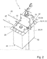
- the Figures 1a, 1b and 2 show a device 1 for opening and closing a maintenance opening 3 provided in a top wall 2 of a fermentation tank of a biogas plant from different viewing directions and in different states.
- the biogas plant comprises a stirring unit 6, which is held by means of a linear guide on a column 5 which extends through the maintenance opening 3.
- a cable pull with a drive unit 53 arranged outside the fermentation container can be provided.
- the device 1 can be inserted into the maintenance opening 3 and comprises a body 10 for connecting the device 1 to the maintenance opening 3 of the fermentation container and a closure element 20 for optionally opening and closing the maintenance opening 3.
- the body 10 comprises a closed frame 11 which can be screwed to an edge region 4 of the maintenance opening 3.
- the frame 11 has a circumferential first contact surface 12 which, when the device 1 is installed as intended, bears against the edge region 4 of the maintenance opening 3.
- the frame 11 has a circumferential second contact surface 13, against which the closure element 20 bears in a closed position of the closure element 20.
- the frame 11 also has a plurality of flat connecting struts 14 which, spaced apart from one another and distributed along the circumference of the frame 11, each extend perpendicularly between the first contact surface 12 and the second contact surface 13 and have a trapezoidal outer contour.
- the device 1 comprises a maintenance flap 16 which is pivotably held on the frame. It is only accessible when the maintenance opening 3 is open and allows the maintenance opening 3 to be opened and closed independently of the closure element 20.
- the closure element 20 is removably arranged on the device 1 and detachably connected to the body 10, but can also be rotatably mounted on the body 10 and can be pivoted between a closed position and an open position of the closure element 20.
- the closure element 20 comprises a plate 21 made of a metal, which has two plate sections 22, 23 which extend perpendicular to one another and are connected to one another at a common edge 24. In the closed position of the closure element 20, a plate section 23 laterally closes a box-shaped structure 15 of the body 10.
- the closure element 20 has two elongate reinforcement profiles 25 which can be screwed to a plate section 22 and which, when screwed as intended, extend parallel to one another and parallel to the plate section 22.
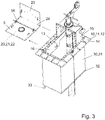
- the device 1 comprises a partition 30 for separating a volume below the maintenance opening 3 and an actuating mechanism for optionally lowering and raising the partition 30 between one Figure 1a shown raised rest position and one in the Figures 2 and 3 lowered position shown.
- the partition wall 30 is fastened to the body 10 and is designed for the gas-tight connection of a liquid level arranged in the interior of the fermentation container to the body 10 and comprises a tubular apron 31. It consists of a fabric made of plastic, but can also be made of another material his. Furthermore, the tubular apron 31 is designed to be foldable like an accordion, but can also comprise a plurality of wall elements which are designed to be telescopically displaceable relative to one another.
- the partition wall 30 further comprises a rigid frame 32 which is arranged on a free end region of the partition wall 30 facing away from the body 10 and is connected to the latter.
- the partition 30 also has a probe 33 for detecting an electrical resistance.
- the probe 33 is arranged on an end region of the partition 30 facing away from the body 10, is rod-shaped and extends away from the body 10.
- the device 1 comprises a locking mechanism provided on the body 10 for locking and unlocking the closure element 20 in a closed position of the closure element 20.
- the locking mechanism is designed in such a way that the closure element 20 can only be locked and / or unlocked in the lowered, separated position of the partition 30.
- the locking mechanism comprises a passage provided on the body 10, two passages provided on the closure element 20, all of which are flush with one another in the closed position of the closure element 20, and a shaft 56.
- the shaft 56 extends through the passages in a locked state of the locking mechanism and is pulled out of the passages in an unlocked state of the locking mechanism.
- the locking mechanism comprises two cable drums 52 and two cables 51, each connected to a cable drum 52.
- the cable drums 52 can be connected to the shaft 56, so that the shaft 56 in the locked state carries a section of each cable 51 provided for lowering and lifting the partition 30.
- the device 1 further comprises an actuating mechanism 50.
- the actuating mechanism 50 is designed and arranged in such a way that the partition wall 30 is on an opposite side of the partition wall 30 Side of the body 10, that is to say can be actuated on an outside of the fermentation container.
- the actuating mechanism 50 comprises the shaft 56, which is rotatably mounted in the two passages, and the cable drums 52, which are arranged at opposite free ends of the shaft 56 and are each non-rotatably connected to the shaft 56, for the optional winding and unwinding of the cables 51 with a cable drum 52 and a second free end of each cable 51 connected to a free end region of the partition 30 and attached to opposite sides of the frame 32.
- the actuating mechanism 50 has a drive unit 53 for rotatingly driving the shaft 56, which comprises a crank 54 in the form of a braked ratchet crank which can be releasably connected to a cable drum 52.
- the actuation mechanism 50 further comprises a deflection roller 55 which is rotatably mounted on the body 10 for guiding the cable 51 and which extends from an outside of the device 1 to an inside of the device 1 through a cable opening provided in the body 10.
- closure element 20 When the closure element 20 is actuated, the closure element 20 is only opened when the partition 30 is lowered, ie when the device 1 is connected in a gastight manner to the liquid level in the interior of the fermentation container through the partition 30. As in Figure 2 shown, a cable drum 52 is released from the shaft 56 and the shaft 56 is laterally pulled out of the passages in order to unlock the closure element 20. In addition, the two reinforcement profiles 25 are loosened and removed. The closure element 20 is then released from the device 1 and moved from the closed position into an open position, as in FIG Figure 3 is shown.
- the closure element 20 is closed before the partition 30 is lifted, i.e. the partition 30 is only raised from the liquid level when the closure element 20 is closed.
- An essential advantage of the device 1 according to the invention is that the partition reliably prevents an uncontrolled escape of a predominant portion of the biogas present in the fermentation tank to the outside.
- the device can also use a locking mechanism to ensure that the maintenance opening is only closed or released when the partition is lowered.
- the invention includes:
- a device for opening and closing a maintenance opening provided in a top wall of a fermentation container with a body for connecting the device to a maintenance opening of a fermentation container and a closure element for optionally opening and closing the maintenance opening, a partition for separating a volume below the maintenance opening and an actuating mechanism to selectively lower and raise the Partition between a raised rest position and a lowered separation position.
- a device according to the invention for opening and closing a maintenance opening provided in a top wall of a fermentation container, comprising a locking mechanism provided on the device, in particular on the body, for locking and unlocking the closure element in a closed position of the closure element.
- a device according to the invention for opening and closing a maintenance opening provided in a top wall of a fermentation container, the locking mechanism being designed such that the closure element can be locked and / or unlocked only in the lowered separation position of the partition.
- a device for opening and closing a maintenance opening provided in a top wall of a fermentation container as explained above, wherein the locking mechanism has a passage provided on the body and one on the closure element Passage, which are aligned with each other in the closed position of the closure element, and comprises a shaft, wherein the shaft extends through the two passages in a locked state of the locking mechanism and is pulled out of the two passages in an unlocked state of the locking mechanism.
- a device for opening and closing a maintenance opening provided in a top wall of a fermentation container as explained above, wherein the locking mechanism comprises a cable drum and a cable connected to the cable drum.
- a device for opening and closing a maintenance opening provided in a top wall of a fermentation container as explained above, the shaft in the locked state carrying a section of the cable provided for lowering and raising the partition.
- a device for opening and closing of a maintenance opening provided in a top wall of a fermentation container comprising the shaft rotatably mounted in the two passages and the cable drum rotatably connected to the shaft for optionally winding and unrolling the cable.
- a device for opening and closing a maintenance opening provided in a top wall of a fermentation container wherein a first free end of the cable connects with the Rope drum and a second free end of the rope are connected to a free end region of the partition.
- a device for opening and closing a maintenance opening provided in a top wall of a fermentation container comprising a crank which can be detachably connected to the cable drum, in particular a braked ratchet crank.
- a device for opening and closing a maintenance opening provided in a top wall of a fermentation container as previously explained, the partition wall comprising a tubular apron.
- a device for opening and closing a maintenance opening provided in a top wall of a fermentation container as previously explained, the partition wall or the apron being designed to be accordion-like foldable.
- a device for opening and closing a maintenance opening provided in a top wall of a fermentation container comprising a rigid frame which is arranged in particular at a free end region of the partition wall and is connected to the latter.
- a device for opening and closing a maintenance opening provided in a top wall of a fermentation container as previously explained, the frame being arranged on an end region facing the body and / or on an end region facing away from the body of the partition.
- a device for opening and closing a maintenance opening provided in a top wall of a fermentation container as explained above, the partition wall comprising a plurality of wall elements.
- a device for opening and closing a maintenance opening provided in a top wall of a fermentation container as explained above, the wall elements being designed and arranged to be telescopically displaceable relative to one another.
- a device for opening and closing a maintenance opening provided in a top wall of a fermentation container as explained above, wherein the probe is arranged on an end region of the partition facing away from the body and / or is rod-shaped and in particular extends away from the body.
- a device for opening and closing a maintenance opening provided in a top wall of a fermentation container as explained above, wherein the plate has two plate sections, which in particular extend perpendicular to one another and / or are connected to one another at a common edge.
- a device for opening and closing of a maintenance opening provided in a top wall of a fermentation container as explained above, wherein in a closed position of the closure element a plate section laterally closes a box-shaped structure of the body.
- a device for opening and closing a maintenance opening provided in a top wall of a fermentation container wherein the closure element has two or more than two reinforcement profiles, which extend in particular parallel to one another and / or in each case parallel to the plate section.
- a device for opening and closing a maintenance opening provided in a top wall of a fermentation container, the closure element being arranged on the device such that it can be removed or rotatably mounted.
- a device for opening and closing a maintenance opening provided in a top wall of a fermentation container as explained above, wherein the closure element is detachably connected to the body or is pivotably held on the body between a closed position and an open position of the closure element.
- a device for opening and closing as provided above provided in a top wall of a fermentation container Maintenance opening, the device being insertable into the maintenance opening.
- a device for opening and closing a maintenance opening provided in a top wall of a fermentation container as explained above, wherein the body comprises a closed frame which can be connected, in particular screwed, to an edge region of the maintenance opening.
- a device for opening and closing of a maintenance opening provided in a top wall of a fermentation container as explained above, wherein the frame has a circumferential first contact surface which, when the device is installed as intended, lies against the edge region of the maintenance opening.
- a device for opening and closing a maintenance opening provided in a top wall of a fermentation container as previously explained, the frame having a circumferential second contact surface against which the closure element bears in a closed position of the closure element.
- a device for opening and closing a maintenance opening provided in a top wall of a fermentation container wherein the frame has a plurality of flat connecting struts, which in particular extend perpendicularly between the first contact surface and the second contact surface and / or have a trapezoidal outer contour.
- the invention further comprises:
- a biogas plant comprising a fermentation tank with a maintenance opening formed in a top wall of the fermentation tank and a device according to the invention and / or a device that is operated in a method according to the invention.
- a biogas plant comprising a device according to the invention and / or a device which is operated in a method according to the invention.
- the invention also includes:
- a method for opening a closure element for a fermentation tank of a biogas plant according to the invention wherein the closure element is only opened when the partition is lowered.
- the invention further comprises:
- a method for closing a closure element for a fermentation tank of a biogas plant according to the invention wherein the closure element is closed before the partition is raised.
Abstract
Die Erfindung betrifft eine Vorrichtung zum Öffnen und Schließen einer in einer Deckwand eines Fermentierbehälters vorgesehenen Wartungsöffnung mit einem Verschlusselement zum wahlweisen Öffnen und Schließen der Wartungsöffnung wobei eine Trennwand zum gasdichten Abtrennen eines Volumens unterhalb der Wartungsöffnung vorgesehen ist. Die Erfindung betrifft weiterhin eine Biogasanlage mit einer Wartungsöffnung und ein Verfahren zum Öffnen eines Verschlusselementes einer Biogasanlage.The invention relates to a device for opening and closing a maintenance opening provided in a top wall of a fermentation container with a closure element for optionally opening and closing the maintenance opening, a partition being provided for the gas-tight separation of a volume below the maintenance opening. The invention further relates to a biogas plant with a maintenance opening and a method for opening a closure element of a biogas plant.
Description
Die Erfindung betrifft eine Vorrichtung zum Öffnen und Schließen einer in einer Deckwand eines Fermentierbehälters vorgesehenen Wartungsöffnung, mit einem Körper zum Verbinden der Vorrichtung mit einer Wartungsöffnung eines Fermentierbehälters und einem Verschlusselement zum wahlweisen Öffnen und Schließen der Wartungsöffnung. Ferner betrifft die Erfindung eine Biogasanlage und ein Verfahren zum Öffnen und Schließen einer in einer Deckwand eines Fermentierbehälters vorgesehenen Wartungsöffnung.The invention relates to a device for opening and closing a maintenance opening provided in a top wall of a fermentation container, with a body for connecting the device to a maintenance opening of a fermentation container and a closure element for optionally opening and closing the maintenance opening. The invention further relates to a biogas plant and a method for opening and closing a maintenance opening provided in a top wall of a fermentation container.
Fermentierbehälter dienen in Biogasanlagen dazu, ein in dem Fermentierbehälter angeordnetes überwiegend flüssiges Substrat zu fermentieren. Das Substrat kann beispielsweise Exkremente von Nutzvieh und pflanzliche Abfälle enthalten.In biogas plants, fermentation tanks serve to supply a predominantly liquid substrate arranged in the fermentation tank ferment. The substrate can contain excrement from livestock and vegetable waste, for example.
Ein bei der Fermentation des Substrats gebildetes Biogas steigt aus dem Substrat nach oben und reichert sich in einem Volumen des Fermentierbehälters oberhalb eines Flüssigkeitsspiegels des Substrats an. Zum Ableiten des Biogases aus dem Ferientierbehälter ist eine Fluidleitung vorgesehen, welche mit dem das Biogas enthaltenden Volumen des Fermentierbehälters fluidverbunden ist. Das auf diese Weise gewonnene Biogas kann beispielsweise zum Antreiben eines Fahrzeugs oder zum Erzeugen einer elektrischen Energie verwendet werden.A biogas formed during the fermentation of the substrate rises from the substrate and accumulates in a volume of the fermentation container above a liquid level of the substrate. To discharge the biogas from the holiday animal container, a fluid line is provided which is fluidly connected to the volume of the fermentation container containing the biogas. The biogas obtained in this way can be used, for example, to drive a vehicle or to generate electrical energy.
Um den Wirkungsgrad der Fermentation zu erhöhen, umfassen Biogasanlagen gewöhnlich Rühreinheiten mit Propellern. Die Propeller sind in dem Substrat unterhalb des Flüssigkeitsspiegels angeordnet und können durch Rotieren das Substrat kontinuierlich oder in zeitlichen Intervallen bewegen und durchmischen, wodurch der Fermentation abträgliche Inhomogenitäten des Substrats, insbesondere einer Bildung von Schichten in dem Substrat entgegengewirkt wird.To increase the efficiency of the fermentation, biogas plants usually include stirring units with propellers. The propellers are arranged in the substrate below the liquid level and can rotate and mix the substrate continuously or at intervals in time by rotating, thereby counteracting the fermentation-causing inhomogeneities of the substrate, in particular the formation of layers in the substrate.
Allerdings muss eine solche Rühreinheit, die auch als Rührwerk bezeichnet wird, regelmäßig gewartet und im Falle eines Defektes auch repariert oder ausgetauscht werden. Dies ist praktisch ausgeschlossen, wenn die Rühreinheit in dem Substrat angeordnet ist. Deshalb sind in einer Deckwand des Fermentierbehälters eine Wartungsöffnung und in dem Fermentierbehälter eine sich durch die Wartungsöffnung erstreckende Säule vorgesehen, an der die Rühreinheit mittels einer Linearführung verschiebbar gehalten ist. Zum Zwecke der Wartung oder Reparatur kann die Rühreinheit entlang der Säule an eine Außenseite des Fermentierbehälters verfahren werden, wo sie für Fachpersonal einfach zugänglich ist.However, such a stirring unit, which is also referred to as an agitator, must be regularly serviced and, in the event of a defect, also repaired or replaced. This is practically impossible if the stirring unit is arranged in the substrate. A maintenance opening is therefore provided in a top wall of the fermentation container and a column extending through the maintenance opening is provided in the fermentation container, on which column the stirring unit is held displaceably by means of a linear guide. For the purpose of maintenance or repair, the stirring unit can be moved along the column to an outside of the fermentation tank, where it is easily accessible for specialist personnel.
Während des normalen Betriebs der Biogasanlage ist die Wartungsöffnung durch eine entsprechende Vorrichtung geschlossen, damit das Biogas nicht unkontrolliert durch die Wartungsöffnung austreten kann. Zum Warten oder Reparieren der Rühreinheit muss die Wartungsöffnung dagegen freigegeben werden, so dass das Biogas ungenutzt durch die Wartungsöffnung nach außen entweicht. Zum einen geht bereits gebildetes Biogas auf diese Weise verloren, zum anderen ist das gebildete Biogas leicht entzündlich, was mit einer entsprechenden Brand- und Explosionsgefahr außerhalb des Fermentierbehälters einhergeht. Abgesehen davon belastet das Biogas wie ein Treibgas die Umwelt.During normal operation of the biogas plant, the maintenance opening is closed by an appropriate device so that the biogas cannot escape through the maintenance opening in an uncontrolled manner. In order to maintain or repair the stirring unit, the maintenance opening must be opened so that the biogas escapes unused through the maintenance opening. On the one hand, biogas that has already been formed is lost in this way, and on the other hand, the biogas that is formed is highly flammable, which is associated with a corresponding risk of fire and explosion outside the fermentation tank. Apart from that, the biogas pollutes the environment like a propellant.
Es ist daher eine Aufgabe der vorliegenden Erfindung, eine Vorrichtung der eingangs genannten Art zu schaffen, die bei einer Wartung oder Reparatur der Rühreinheit einem Entweichen des Biogases entgegenwirkt.It is therefore an object of the present invention to provide a device of the type mentioned at the outset which counteracts the escape of the biogas during maintenance or repair of the stirring unit.
Gegenstand der Erfindung ist eine Vorrichtung zum Öffnen und Schließen einer in einer Deckwand eines Fermentierbehälters vorgesehenen Wartungsöffnung, mit einem Körper zum Verbinden der Vorrichtung mit einer Wartungsöffnung eines Fermentierbehälters und einem Verschlusselement zum wahlweisen Öffnen und Schließen der Wartungsöffnung. Mit anderen Worten schlägt die Erfindung eine Vorrichtung vor, welche ein Öffnen und Schließen der Wartungsöffnung mit einem Verschlusselement erlaubt.The invention relates to a device for opening and closing a maintenance opening provided in a top wall of a fermentation container, having a body for connecting the device to a maintenance opening of a fermentation container and a closure element for optionally opening and closing the maintenance opening. In other words, the invention proposes a device which allows the maintenance opening to be opened and closed with a closure element.
Erfindungsgemäß umfasst die Vorrichtung eine Trennwand zum Abtrennen eines Volumens unterhalb der Wartungsöffnung und einen Betätigungsmechanismus zum wahlweisen Absenken und Anheben der Trennwand zwischen einer angehobenen Ruhestellung und einer abgesenkten Trennstellung. Die Trennwand ist demnach ausgebildet, wahlweise ein Volumen im Inneren des Fermentierbehälters abzutrennen. Dazu ist sie aus einer Ruhestellung, in der sie kein Volumen abtrennt, in eine Trennstellung, in der sie das Volumen abtrennt, absenkbar oder aus der Trennstellung in die Ruhestellung anhebbar.According to the invention, the device comprises a partition wall for separating a volume below the maintenance opening and an actuating mechanism for selectively lowering and raising the partition wall between a raised rest position and a lowered separation position. The partition is accordingly designed to selectively separate a volume inside the fermentation container. To do this, it is from a rest position in which it does not separate any volume, into a separation position in which it separates the volume, can be lowered or raised from the separation position to the rest position.
Erfindungsgemäß ist ein an der Vorrichtung, insbesondere an dem Körper vorgesehener Verriegelungsmechanismus zum Verriegeln und Entriegeln des Verschlusselements in einer Schließstellung des Verschlusselements vorgesehen. Durch den Verriegelungsmechanismus kann sichergestellt werden, dass das Verschlusselement nicht versehentlich aus seiner Schließstellung fortbewegt wird. Ein Fortbewegen des verriegelten Verschlusselements ist ausgeschlossen. Lediglich das entriegelte Verschlusselement kann aus der Schließstellung fortbewegt werden.According to the invention, a locking mechanism is provided on the device, in particular on the body, for locking and unlocking the closure element in a closed position of the closure element. The locking mechanism can ensure that the closure element is not inadvertently moved out of its closed position. Moving the locked closure element is excluded. Only the unlocked locking element can be moved out of the closed position.
Weiterhin ist erfindungsgemäß vorgesehen, dass der Verriegelungsmechanismus derart ausgebildet ist, dass das Verschlusselement nur in der abgesenkten Trennstellung der Trennwand verriegelbar und/oder entriegelbar ist. Infolgedessen kann der Verriegelungsmechanismus nicht betätigt werden, wenn die Trennwand in einer anderen als der abgesenkten Trennstellung ist. Dadurch werden Fehlbedienungen unmöglich gemacht und die Arbeitssicherheit an der Vorrichtung signifikant verbessert.Furthermore, it is provided according to the invention that the locking mechanism is designed such that the closure element can only be locked and / or unlocked in the lowered, separated position of the partition. As a result, the locking mechanism cannot be operated when the partition is in a position other than the lowered separation position. This makes incorrect operation impossible and significantly improves work safety on the device.
Bei einer bevorzugten Ausgestaltung des Vorschlags ist vorgesehen, dass die Trennwand zum gasdichten Verbinden eines in dem Inneren des Fermentierbehälters angeordneten Flüssigkeitsspiegels mit dem Körper ausgebildet ist. Entsprechend kann die Trennwand derart abgesenkt werden, dass sie in ein in dem Fermentierbehälter vorhandenes überwiegend flüssiges Substrat eingetaucht ist.In a preferred embodiment of the proposal it is provided that the partition is designed for the gas-tight connection of a liquid level arranged in the interior of the fermentation container to the body. Accordingly, the partition can be lowered in such a way that it is immersed in a predominantly liquid substrate present in the fermentation container.
Geschickter Weise ist vorgesehen, dass der Verriegelungsmechanismus einen an dem Körper vorgesehenen Durchlass, einen an dem Verschlusselement vorgesehenen Durchlass, die in der Schließstellung des Verschlusselements miteinander fluchten, und eine Welle umfasst, wobei die Welle die beiden Durchlässe in einem verriegelten Zustand des Verriegelungsmechanismus durchgreift und in einem entriegelten Zustand des Verriegelungsmechanismus aus den beiden Durchlässen herausgezogen ist. Mit anderen Worten wirkt die Welle als ein Riegel, der zum Verriegeln durch die beiden Durchlässe gesteckt wird und zum Entriegeln aus diesen entfernt wird.Cleverly, it is provided that the locking mechanism comprises a passage provided on the body, a passage provided on the closure element, which are aligned with one another in the closed position of the closure element, and a shaft, the shaft penetrating the two passages in a locked state of the locking mechanism and is pulled out of the two passages in an unlocked state of the locking mechanism. In other words, the shaft acts as a bolt which is inserted through the two passages for locking and is removed from these for unlocking.
Des Weiteren ist günstiger Weise vorgesehen, dass der Verriegelungsmechanismus eine an der Welle befestigte Seiltrommel und ein mit der Seiltrommel verbundenes Seil umfasst. Mittels des Seils lässt sich die Welle mit einer Kraft beaufschlagen, um die Welle in den beiden Durchlässen festzulegen und ein Entriegeln auszuschließen.Furthermore, it is advantageously provided that the locking mechanism comprises a cable drum attached to the shaft and a cable connected to the cable drum. The rope can be used to apply a force to the shaft in order to fix the shaft in the two passages and to prevent unlocking.
Vorteilhafter Weise ist vorgesehen, dass die Welle im verriegelten Zustand einen zum Absenken und Anheben der Trennwand vorgesehenen Abschnitt des Seils trägt. Der zum Bewegen der Trennwand vorgesehene Abschnitt kann in der Seiltrommel aufgerollt sein. Wenn die Trennwand nicht in ihrer Trennstellung ist, ist das Seil gespannt und die Welle mit einer Gewichtskraft der Trennwand beaufschlagt. Wenn dagegen die Trennwand in ihrer Trennstellung ist, ist das Seil entspannt und die Welle nicht mit der Gewichtskraft beaufschlagt. Aufgrund dessen lässt sich die Welle ausschließlich in der Trennstellung aus den Durchlässen herausziehen, weshalb ein Entriegeln des Verschlusselements nur in der Trennstellung möglich ist.It is advantageously provided that in the locked state the shaft carries a section of the cable provided for lowering and raising the partition. The section provided for moving the partition wall can be rolled up in the cable drum. If the partition is not in its separation position, the rope is tensioned and the weight of the partition is loaded on the shaft. If, on the other hand, the partition is in its separation position, the rope is relaxed and the weight is not applied to the shaft. Because of this, the shaft can only be pulled out of the passages in the disconnected position, which is why it is only possible to unlock the closure element in the disconnected position.
Geschickter Weise ist vorgesehen, dass der Betätigungsmechanismus derart ausgebildet und angeordnet ist, dass die Trennwand auf einer der Trennwand gegenüberliegenden Seite des Körpers betätigbar ist. Ein solcher Betätigungsmechanismus erlaubt ein komfortables Betätigen der Trennwand außerhalb des Fermentierbehälters.Cleverly it is provided that the actuating mechanism is designed and arranged in such a way that the partition can be actuated on a side of the body opposite the partition is. Such an actuation mechanism allows the partition to be actuated comfortably outside the fermentation container.
In einer vorteilhaften Ausgestaltung ist vorgesehen, dass der Betätigungsmechanismus die in den beiden Durchlässen drehbar gelagerte Welle und die mit der Welle drehfest verbundene Seiltrommel zum wahlweisen Aufrollen und Abrollen des Seils umfasst. Damit haben die Seiltrommel und das Seil eine Doppelfunktion. Sie wirken nicht nur innerhalb des Verriegelungsmechanismus, sondern können auch zum Bewegen der Trennwand verwendet werden.In an advantageous embodiment it is provided that the actuating mechanism comprises the shaft rotatably mounted in the two passages and the cable drum rotatably connected to the shaft for the optional winding and unwinding of the cable. The rope drum and the rope thus have a dual function. They not only act within the locking mechanism, but can also be used to move the partition.
In weiteren Ausgestaltungen sind ein erstes freies Ende des Seils mit der Seiltrommel und ein zweites freies Ende des Seils mit einem freien Endbereich der Trennwand verbunden. Entsprechend ist das Seil in der Trennstellung der Trennwand von der Seiltrommel im Wesentlichen vollständig abgerollt und in der Ruhestellung der Trennwand in der Seiltrommel im Wesentlichen aufgerollt.In further refinements, a first free end of the rope is connected to the rope drum and a second free end of the rope is connected to a free end region of the partition. Accordingly, the rope is essentially completely unrolled from the rope drum in the separating position of the dividing wall and essentially rolled up in the rope drum when the dividing wall is in the rest position.
In einer weiteren bevorzugten Ausführungsform ist vorgesehen, dass der Betätigungsmechanismus und/oder der Verriegelungsmechanismus zwei Seiltrommeln, die an gegenüberliegenden freien Enden der Welle angeordnet sind, und zwei Seile umfasst, die mit gegenüberliegenden freien Endbereichen der Trennwand verbunden sind. Mittels zweier Seile lässt sich die Trennwand symmetrisch mit einer Kraft beaufschlagen, wodurch eine Gefahr eines Verkantens der Trennwand während des Absenkens oder Anhebens verringert wird.In a further preferred embodiment it is provided that the actuating mechanism and / or the locking mechanism comprises two cable drums which are arranged at opposite free ends of the shaft and two cables which are connected to opposite free end regions of the partition. A force can be applied to the partition wall symmetrically by means of two ropes, thereby reducing the risk of the partition wall tilting during lowering or lifting.
Des Weiteren ist günstiger Weise vorgesehen, dass der Betätigungsmechanismus eine Antriebseinheit zum drehenden Antreiben der Welle aufweist. Die Antriebseinheit erlaubt ein erleichtertes Drehen der Welle.Furthermore, it is advantageously provided that the actuating mechanism has a drive unit for rotatingly driving the shaft. The drive unit allows the shaft to be turned more easily.
Vorteilhafterweise umfasst die Antriebseinheit eine mit der Seiltrommel lösbar verbindbare Kurbel, insbesondere eine gebremste Ratschenkurbel. Die Kurbel bildet eine in der Handhabung besonders einfache Antriebseinheit für ein manuelles Bewegen der Trennwand. Sie kann zum Bewegen der Trennwand mit der Welle drehfest verbunden werden und nach einem Bewegen der Trennwand von der Welle gelöst werden. Eine gebremste, d.h. unidirektional verrastende Ratschenkurbel kann die zum Aufrollen des Seils erforderliche Kraft verringern.The drive unit advantageously comprises a crank that can be detachably connected to the cable drum, in particular a braked one Ratchet crank. The crank forms a drive unit that is particularly easy to handle for manually moving the partition. It can be connected in a rotationally fixed manner to move the partition wall and can be detached from the shaft after moving the partition wall. A braked, ie unidirectionally locking ratchet crank can reduce the force required to wind up the rope.
Geschickter Weise ist vorgesehen, dass der Betätigungsmechanismus zu einem, insbesondere zu jedem Seil eine an dem Körper drehbar gelagerte Umlenkrolle zum Führen des Seils umfasst. Dank der Umlenkrolle ist die Flexibilität bei der Führung des Seils vergrößert.Cleverly, it is provided that the actuating mechanism for a, in particular for each rope, comprises a deflection roller rotatably mounted on the body for guiding the rope. Thanks to the deflection roller, the flexibility in guiding the rope is increased.
In einer Ausführungsform erstreckt sich jedes Seil durch eine in dem Körper vorgesehene Seilöffnung. Die Seilöffnung ist ein einfaches Mittel, um das Seil von der der Trennwand gegenüberliegenden Seite des Körpers auf die der Trennwand zugewandten Seite des Körpers zu führen.In one embodiment, each rope extends through a rope opening provided in the body. The rope opening is a simple means of guiding the rope from the side of the body opposite the partition to the side of the body facing the partition.
Vorteilhaft kann die Trennwand einen Kunststoff umfassen oder aus einem Kunststoff bestehen. Kunststoffe stehen in einer großen Vielfalt zur Verfügung und sind bei der Herstellung einfach zu handhaben.The partition can advantageously comprise a plastic or consist of a plastic. A wide variety of plastics are available and are easy to handle during manufacture.
Alternativ oder zusätzlich kann die Trennwand ein Gewebe umfassen oder aus einen Gewebe bestehen. Gewebe können eine leichte Biegbarkeit und eine starke Zugfestigkeit aufweisen.Alternatively or additionally, the partition wall can comprise a woven fabric or consist of a woven fabric. Fabrics can be easily bendable and have high tensile strength.
Bei einer bevorzugten Ausgestaltung des Vorschlags ist vorgesehen, dass die Trennwand eine schlauchförmige Schürze umfasst. Die Schlauchform umschließt in der Trennstellung der Trennwand einen relativ kleines mit der Wartungsöffnung fluidverbundenes Volumen und ggf. eine sich durch das Volumen aus dem Inneren des Fermentierbehälters durch die Wartungsöffnung nach außen erstreckende Säule. Ein in diesem von der Trennwand umschlossenen Volumen vorhandenes Biogas kann in der Offenstellung des Verschlusselements unkontrolliert durch die Wartungsöffnung nach außen entweichen. Allerdings ist das relativ größere Volumen an der Außenseite der Trennwand von der Wartungsöffnung gasdicht getrennt, so dass das dort angeordnete Biogas nicht unkontrolliert durch die Wartungsöffnung nach außen entweichen kann und daher während einer Wartung oder Reparatur der Rühreinheit in dem Fermentierbehälter verbleibt.In a preferred embodiment of the proposal it is provided that the partition comprises a tubular apron. In the separating position of the dividing wall, the tubular shape encloses a relatively small volume that is fluidly connected to the maintenance opening and, if appropriate, one that is separated by the volume from the inside of the fermentation container through the maintenance opening extending column. A biogas present in this volume enclosed by the partition wall can escape uncontrolled through the maintenance opening in the open position of the closure element. However, the relatively larger volume on the outside of the partition is separated from the maintenance opening in a gas-tight manner, so that the biogas arranged there cannot escape uncontrolled through the maintenance opening and therefore remains in the fermentation container during maintenance or repair of the stirring unit.
Vorteilhaft ist die Schürze bzw. die Trennwand ziehharmonikaartig faltbar ausgebildet. Dadurch ist das Absenken und Anheben der Trennwand erleichtert, und die Trennwand benötigt in der Ruhestellung wenig Raum.The apron or the partition wall is advantageously designed to be accordion-like foldable. This makes it easier to lower and raise the partition, and the partition requires little space in the rest position.
Geschickter Weise ist vorgesehen, dass die Trennwand einen starren Rahmen umfasst, der insbesondere an einem freien Endbereich der Trennwand angeordnet und mit diesem verbunden ist. Der Rahmen stabilisiert die Trennwand und definiert entsprechend seiner Form eine Querschnittsfläche der Trennwand.Cleverly it is provided that the partition wall comprises a rigid frame, which is arranged in particular at a free end region of the partition wall and is connected to it. The frame stabilizes the partition and defines a cross-sectional area of the partition according to its shape.
Bei weiteren Ausgestaltungen ist der Rahmen an einem dem Körper zugewandten Endbereich und/oder an einem dem Körper abgewandten Endbereich der Trennwand angeordnet. Bei dieser Anordnung sorgt der Rahmen für eine in der Trennstellung der Trennwand über die gesamte Länge der Trennwand im Wesentlichen konstante Querschnittsfläche.In further configurations, the frame is arranged on an end region facing the body and / or on an end region of the partition facing away from the body. With this arrangement, the frame ensures a substantially constant cross-sectional area in the separating position of the dividing wall over the entire length of the dividing wall.
Alternativ kann die Trennwand mehrere Wandelemente umfassen. Auch die aus mehreren Wandelementen gebildete Trennwand kann durch Verschieben der Wandelemente in ihrer Länge geändert werden, um sie zwischen der Ruhestellung und der Trennstellung zu bewegen.Alternatively, the partition can comprise several wall elements. The length of the partition wall formed from several wall elements can also be changed by moving the wall elements in order to move them between the rest position and the separation position.
Bei dieser Ausgestaltung können die Wandelemente relativ zueinander teleskopartig verschiebbar ausgebildet und angeordnet sein. Auf diese Weise lässt sich eine bewährte und einfache Längenvariabilität der Trennwand schaffen.In this configuration, the wall elements can be designed and arranged to be telescopically displaceable relative to one another. In this way, a proven and simple length variability of the partition can be created.
Bevorzugt ist die Trennwand an dem Körper befestigt. Die Befestigung an dem Körper verhindert, dass Biogas zwischen dem Körper und der Trennwand unkontrolliert nach außen entweichen kann. Zudem trägt der Körper die Trennwand in der Trennstellung, wodurch das Seil entlastet und das Abschlusselement entriegelbar ist.The partition is preferably attached to the body. The attachment to the body prevents biogas from escaping uncontrollably between the body and the partition. In addition, the body supports the partition in the disconnected position, relieving the rope and unlocking the end element.
Bei vorteilhaften Ausgestaltungen weist die Trennwand eine Sonde, insbesondere zum Erfassen eines elektrischen Widerstands auf. Der elektrische Widerstand einer Strecke innerhalb des Substrats ist geringer als der elektrische Widerstand derselben Strecke außerhalb des Substrats, d.h. innerhalb des über Flüssigkeitsspiegel des Substrats angeordneten Biogases. Deshalb kann durch eine Messung des elektrischen Widerstands die vertikale Position des Flüssigkeitsspiegels bestimmt werden. Es eignen sich aber auch andere Sonden, die in der Lage sind, die Anwesenheit des Flüssigkeitsspiegels zu entdecken, z.B. kapazitive oder auch optische Sensoren.In advantageous configurations, the partition wall has a probe, in particular for detecting an electrical resistance. The electrical resistance of a path inside the substrate is lower than the electrical resistance of the same path outside the substrate, i.e. within the biogas arranged above the liquid level of the substrate. Therefore, the vertical position of the liquid level can be determined by measuring the electrical resistance. However, other probes that are able to detect the presence of the liquid level are also suitable, e.g. capacitive or optical sensors.
Geschickter Weise ist vorgesehen, dass die Sonde an einem dem Körper abgewandten Endbereich der Trennwand angeordnet ist und/oder stabförmig ausgebildet ist und sich insbesondere von dem Körper weg weisend erstreckt. Mit anderen Worten lässt sich auf diese Weise feststellen, ob die Trennwand bis zu dem Substrat reicht oder in das Substrat eingetaucht ist, also den gesamten Abstand zwischen der Wartungsöffnung und dem Flüssigkeitsspiegel überbrückt. Wenn eine weitere derartige Sonde zusätzlich an der Rühreinheit angebracht ist, lässt sich schaltungstechnisch vorsehen, dass die Rühreinheit nur betrieben werden kann, wenn die Rühreinheit unterhalb des Flüssigkeitsspiegels und das freie Ende der Trennwand oberhalb des Flüssigkeitsspiegels angeordnet ist. Infolge dieser räumlichen Trennung von Rühreinheit und Trennwand ist gewährleistet, dass die Trennwand während des Betriebs der Rühreinheit weder durch die Rühreinheit selbst noch durch das von ihr bewegte Substrat beschädigt wird.It is cleverly provided that the probe is arranged on an end region of the partition facing away from the body and / or is rod-shaped and in particular extends away from the body. In other words, it can be determined in this way whether the partition extends to the substrate or is immersed in the substrate, that is to say bridges the entire distance between the maintenance opening and the liquid level. If a further probe of this type is additionally attached to the stirring unit, it can be provided in terms of circuitry that the stirring unit can only be operated if the stirring unit is below the liquid level and the free end of the Partition is arranged above the liquid level. As a result of this spatial separation of the stirring unit and the partition wall, it is ensured that the partition wall is not damaged by the stirring unit itself or by the substrate moved by it during the operation of the stirring unit.
In einer weiteren bevorzugten Ausführungsform ist vorgesehen, dass das Verschlusselement eine Platte umfasst. Platten sind einfach in der Herstellung und Handhabung. Beispielsweise kann das Verschlusselement eine aus einem Metall gefertigte Platte umfassen.In a further preferred embodiment it is provided that the closure element comprises a plate. Plates are easy to manufacture and handle. For example, the closure element can comprise a plate made of a metal.
Vorteilhaft weist die Platte zwei Plattenabschnitte auf, die sich insbesondere senkrecht zueinander erstrecken und/oder an einer gemeinsamen Kante miteinander verbunden sind. Mit einer derart ausgebildeten Platte lassen sich komplexe Öffnungsflächen verschließen.The plate advantageously has two plate sections, which in particular extend perpendicular to one another and / or are connected to one another at a common edge. With such a plate complex opening areas can be closed.
Geschickter Weise ist vorgesehen, dass in der Schließstellung des Verschlusselements ein Plattenabschnitt einen kastenförmigen Aufbau des Körpers seitlich verschließt. Der kastenförmige Aufbau kann eine außerhalb der Wartungsöffnung angeordnete Komponente der Biogasanlage zumindest teilweise einhausen.Cleverly it is provided that in the closed position of the closure element a plate section laterally closes a box-shaped structure of the body. The box-shaped structure can at least partially house a component of the biogas plant arranged outside the maintenance opening.
Bei weiteren Ausführungsformen weist das Verschlusselement ein längliches Verstärkungsprofil auf, das mit einem Plattenabschnitt lösbar verbunden, insbesondere verschraubt ist. Das Verstärkungsprofil dient der stabilen Befestigung des Verschlusselements.In further embodiments, the closure element has an elongated reinforcement profile which is detachably connected, in particular screwed, to a plate section. The reinforcement profile serves for the stable fastening of the closure element.
Vorteilhaft weist das Verschlusselement zwei oder mehr als zwei Verstärkungsprofile auf, die sich insbesondere parallel zueinander und/oder jeweils parallel zu dem Plattenabschnitt erstrecken. Dadurch wird die Stabilität der Befestigung weiter verbessert.The closure element advantageously has two or more than two reinforcement profiles, which in particular extend parallel to one another and / or in each case parallel to the plate section. This further improves the stability of the fastening.
Des Weiteren ist bevorzugt, dass das Verschlusselement an der Vorrichtung demontierbar oder drehbar gelagert angeordnet ist. Mit anderen Worten lässt sich das Verschlusselement von der Vorrichtung lösen oder gegenüber der Vorrichtung verdrehen.Furthermore, it is preferred that the closure element is arranged on the device such that it can be removed or rotatably mounted. In other words, the closure element can be detached from the device or rotated relative to the device.
Das Verschlusselement kann mit dem Körper lösbar verbunden oder an dem Körper zwischen der Schließstellung und einer Offenstellung des Verschlusselements verschwenkbar gehalten sein. Damit ist das Verschlusselement in der Offenstellung von dem Körper entfernt oder gegenüber dem Körper verschwenkt.The closure element can be detachably connected to the body or held pivotably on the body between the closed position and an open position of the closure element. In the open position, the closure element is thus removed from the body or pivoted relative to the body.
Geschickter Weise ist die Vorrichtung in die Wartungsöffnung einsetzbar. Eine Außenkontur der Vorrichtung korrespondiert dazu mit einer Innenkontur der Wartungsöffnung. Infolgedessen bedarf es keiner baulichen Veränderung des Fermentierbehälters, um die Vorrichtung zu verwenden.The device can be skillfully inserted into the maintenance opening. An outer contour of the device corresponds to an inner contour of the maintenance opening. As a result, no structural modification of the fermentation container is required to use the device.
Des Weiteren ist günstiger Weise vorgesehen, dass der Körper einen mit einem Randbereich der Wartungsöffnung verbindbaren, insbesondere verschraubbaren geschlossenen Rahmen umfasst. Im bestimmungsgemäßen Zustand bildet der Rahmen einen die Wartungsöffnung umgebenden Übergangsbereich zwischen der Vorrichtung und dem Fermentierbehälter.Furthermore, it is advantageously provided that the body comprises a closed frame that can be connected, in particular screwed, to an edge region of the maintenance opening. In the intended state, the frame forms a transition area surrounding the maintenance opening between the device and the fermentation container.
Vorteilhaft weist der Rahmen eine umlaufende erste Anlagefläche auf, die im bestimmungsgemäß montierten Zustand der Vorrichtung an dem Randbereich der Wartungsöffnung anliegt. Die Anlagefläche stellt sicher, dass die Vorrichtung gasdicht an den Randbereich der Wartungsöffnung anschließt.The frame advantageously has a circumferential first contact surface which, when the device is installed as intended, lies against the edge region of the maintenance opening. The contact surface ensures that the device connects gastight to the edge area of the maintenance opening.
Ebenso vorteilhaft weist der Rahmen eine umlaufende zweite Anlagefläche auf, an der das Verschlusselement in der Schließstellung des Verschlusselements anliegt. Die zweite Anlagefläche stellt sicher, dass das Verschlusselement gasdicht an dem Körper der Vorrichtung anliegt.The frame also has a circumferential second contact surface against which the closure element bears in the closed position of the closure element. The second contact surface ensures that the closure element lies gas-tight on the body of the device.
In weiteren Ausgestaltungen weist der Rahmen eine Mehrzahl von flachen Verbindungsstreben auf, die sich insbesondere senkrecht zwischen der ersten Anlagefläche und der zweiten Anlagefläche erstrecken und/oder eine trapezförmige Außenkontur aufweisen. Die Verbindungsstreben verstärken den Rahmen und verringern ein Verformen des Rahmens unter Krafteinwirkung.In further configurations, the frame has a plurality of flat connecting struts, which in particular extend perpendicularly between the first contact surface and the second contact surface and / or have a trapezoidal outer contour. The connecting struts reinforce the frame and reduce deformation of the frame under the action of force.
Gegenstand der Erfindung ist auch eine Biogasanlage, umfassend einen Fermentierbehälter mit einer in einer Deckwand des Fermentierbehälters ausgebildeten Wartungsöffnung. Solche Biogasanlagen sind weit verbreitet, wodurch sich für die vorliegende Erfindung eine Vielzahl von Verwendungsmöglichkeiten ergibt.The invention also relates to a biogas plant comprising a fermentation tank with a maintenance opening formed in a top wall of the fermentation tank. Such biogas plants are widespread, which results in a multitude of possible uses for the present invention.
Erfindungsgemäß umfasst die Biogasanlage eine erfindungsgemäße Vorrichtung und/oder eine Vorrichtung, die in einem erfindungsgemäßen Verfahren bedient wird. Damit ist die Biogasanlage vor einem unkontrollierten Entweichen einer überwiegenden Menge eines in dem Fermentierbehälter vorhandenen Biogases nach außen geschützt.According to the invention, the biogas plant comprises a device according to the invention and / or a device which is operated in a method according to the invention. The biogas plant is thus protected from the outside from an uncontrolled escape of a predominant amount of a biogas present in the fermentation tank.
In weiteren Ausgestaltungen umfasst die Biogasanlage eine Rühreinheit. Die Rühreinheit dient der Homogenisierung eines in der Biogasanlage angeordneten im Wesentlichen flüssigen Substrats und wirkt daher einer unerwünschten Bildung von Schichten in dem Substrat entgegen.In further configurations, the biogas plant includes a stirring unit. The stirring unit serves to homogenize an essentially liquid substrate arranged in the biogas plant and therefore counteracts undesired formation of layers in the substrate.
Ein weiterer Gegenstand der Erfindung ist ein Verfahren zum Öffnen eines Verschlusselements für einen Fermentierbehälter einer erfindungsgemäßen Biogasanlage, wobei ein Öffnen des Verschlusselements erst erfolgt, wenn die Trennwand abgesenkt ist. Bei abgesenkter Trennwand ist zumindest ein Teil eines in dem Fermentierbehälter vorhandenen Biogases an einem unkontrollierten Entweichen durch das geöffnete Verschlusselement nach außen gehindert.Another object of the invention is a method for opening a closure element for a fermentation tank of a biogas plant according to the invention, wherein the closure element is only opened when the partition is lowered. When the partition is lowered, at least part of one is in the fermentation tank existing biogas prevented from uncontrolled escape through the open closure element to the outside.
Vorteilhaft ist vorgesehen, dass ein Öffnen des Verschlusselements erst erfolgt, wenn die Vorrichtung durch die Trennwand gasdicht mit dem Flüssigkeitsspiegel im Inneren des Fermentierbehälters verbunden ist. In dieser Stellung der Trennwand ist ein Volumen innerhalb des Fermentierbehälters von der Wartungsöffnung gasdicht getrennt.It is advantageously provided that the closure element is only opened when the device is connected in a gastight manner to the liquid level in the interior of the fermentation container through the partition. In this position of the partition, a volume inside the fermentation container is separated from the maintenance opening in a gastight manner.
Noch ein Gegenstand der vorliegenden Erfindung ist ein Verfahren zum Schließen eines Verschlusselements für einen Fermentierbehälter einer erfindungsgemäßen Biogasanlage, wobei ein Schließen des Verschlusselements vor einem Anheben der Trennwand erfolgt. Das geschlossene Verschlusselement hindert ein in dem Fermentierbehälter vorhandenes und infolge des Anhebens der Trennwand frei bewegliches Biogas an einem unkontrollierten Entweichen durch die Wartungsöffnung nach außen.Another object of the present invention is a method for closing a closure element for a fermentation tank of a biogas plant according to the invention, wherein the closure element is closed before the partition is raised. The closed closure element prevents a biogas which is present in the fermentation container and which is freely movable as a result of the lifting of the partition wall from uncontrolled escape through the maintenance opening to the outside.
Vorteilhaft ist vorgesehen, dass die Trennwand erst von dem Flüssigkeitsspiegel angehoben wird, wenn das Verschlusselement geschlossen ist. Mit anderen Worten ist ausgeschlossen, dass das die Wartungsöffnung freigegeben ist, nachdem die Trennwand von dem Flüssigkeitsspiegel angehoben ist.It is advantageously provided that the partition is only raised from the liquid level when the closure element is closed. In other words, it is impossible for the maintenance opening to be opened after the partition is raised from the liquid level.
In diesem Zusammenhang wird insbesondere darauf hingewiesen, dass alle im Bezug auf die Vorrichtung beschriebenen Merkmale und Eigenschaften aber auch Verfahrensweisen sinngemäß auch bezüglich der Formulierung des erfindungsgemäßen Verfahrens übertragbar und im Sinne der Erfindung einsetzbar und als mitoffenbart gelten. Gleiches gilt auch in umgekehrter Richtung, das bedeutet, nur im Bezug auf das Verfahren genannte, bauliche also vorrichtungsgemäße Merkmale können auch im Rahmen der Vorrichtungsansprüche berücksichtigt und beansprucht werden und zählen ebenfalls zur Offenbarung.In this context, it is particularly pointed out that all the features and properties described in relation to the device, but also procedures, are analogously also applicable with regard to the formulation of the method according to the invention and can be used in the sense of the invention and are also disclosed. The same also applies in the opposite direction, which means that only structural features that are mentioned in relation to the method, that is to say device features, can also be taken into account within the scope of the device claims and are claimed and also count towards revelation.
In der Zeichnung ist die Erfindung insbesondere in einem Ausführungsbeispiel schematisch dargestellt. Es zeigen:
- Fig. 1a
- in einer Querschnittsdarstellung eine Seitenansicht eine Vorrichtung nach einer Ausführungsform der vorliegenden Erfindung in einer verriegelten Schließstellung des Verschlusselements;
- Fig. 1b
- eine Draufsicht der in
Fig. 1a gezeigten Vorrichtung; - Fig. 2
- in einer perspektivischen Darstellung eine Ansicht der in
Fig. 1a gezeigten Vorrichtung in einer entriegelten Schließstellung des Verschlusselements; - Fig. 3
- in einer perspektivischen Darstellung eine Ansicht der in
Fig. 1a gezeigten Vorrichtung in einer Offenstellung des Verschlusselements.
- Fig. 1a
- in a cross-sectional view a side view of a device according to an embodiment of the present invention in a locked closed position of the closure element;
- Fig. 1b
- a top view of the in
Fig. 1a shown device; - Fig. 2
- a perspective view of the view in
Fig. 1a shown device in an unlocked closed position of the closure element; - Fig. 3
- a perspective view of the view in
Fig. 1a shown device in an open position of the closure element.
In den Figuren sind gleiche oder einander entsprechende Elemente jeweils mit den gleichen Bezugszeichen bezeichnet und werden daher, sofern nicht zweckmäßig, nicht erneut beschrieben. Die in der gesamten Beschreibung enthaltenen Offenbarungen sind sinngemäß auf gleiche Teile mit gleichen Bezugszeichen bzw. gleichen Bauteilbezeichnungen übertragbar. Auch sind die in der Beschreibung gewählten Lageangaben, wie z.B. oben, unten, seitlich usw. auf die unmittelbar beschriebene sowie dargestellte Figur bezogen und sind bei einer Lageänderung sinngemäß auf die neue Lage zu übertragen. Weiterhin können auch Einzelmerkmale oder Merkmalskombinationen aus den gezeigten und beschriebenen unterschiedlichen Ausführungsbeispielen für sich eigenständige, erfinderische oder erfindungsgemäße Lösungen darstellen.In the figures, elements that are the same or correspond to one another are each identified by the same reference numerals and are therefore not described again unless they are expedient. The disclosures contained in the entire description are analogously applicable to the same parts with the same reference numerals or the same component names. The position information selected in the description, such as, for example, top, bottom, side, etc., are based on the figure described and illustrated immediately, and are to be transferred accordingly to the new position in the event of a change in position. Furthermore, individual features or combinations of features from the different exemplary embodiments shown and described can also represent independent, inventive or inventive solutions.
Die
Die Vorrichtung 1 ist in die Wartungsöffnung 3 einsetzbar und umfasst einen Körper 10 zum Verbinden der Vorrichtung 1 mit der Wartungsöffnung 3 des Fermentierbehälters und einem Verschlusselement 20 zum wahlweisen Öffnen und Schließen der Wartungsöffnung 3.The
Der Körper 10 umfasst einen mit einem Randbereich 4 der Wartungsöffnung 3 verschraubbaren geschlossenen Rahmen 11. Der Rahmen 11 weist eine umlaufende erste Anlagefläche 12 aufweist, die im bestimmungsgemäß montierten Zustand der Vorrichtung 1 an dem Randbereich 4 der Wartungsöffnung 3 anliegt. Ferner weist der Rahmen 11 eine umlaufende zweite Anlagefläche 13 auf, an der das Verschlusselement 20 in einer Schließstellung des Verschlusselements 20 anliegt. Der Rahmen 11 weist zudem eine Mehrzahl von flachen Verbindungsstreben 14 auf, die sich beabstandet zueinander und verteilt entlang des Umfangs des Rahmens 11 jeweils senkrecht zwischen der ersten Anlagefläche 12 und der zweiten Anlagefläche 13 erstrecken und eine trapezförmige Außenkontur aufweisen. Die Vorrichtung 1 umfasst eine Wartungsklappe 16, die an dem Rahmen verschwenkbar gehalten ist. Sie ist nur bei einer geöffneten Wartungsöffnung 3 zugänglich und erlaubt ein Öffnen und Schließen der Wartungsöffnung 3 unabhängig von dem Verschlusselement 20.The body 10 comprises a closed frame 11 which can be screwed to an edge region 4 of the
Das Verschlusselement 20 ist an der Vorrichtung 1 demontierbar angeordnet und mit dem Körper 10 lösbar verbunden, kann aber auch an dem Körper 10 drehbar gelagert und wischen einer Schließstellung und einer Offenstellung des Verschlusselements 20 verschwenkbar gehalten sein.The
Das Verschlusselement 20 umfasst eine aus einem Metall gefertigte Platte 21, die zwei Plattenabschnitte 22, 23 aufweist, die sich senkrecht zueinander erstrecken und an einer gemeinsamen Kante 24 miteinander verbunden sind. In der Schließstellung des Verschlusselements 20 verschließt ein Plattenabschnitt 23 einen kastenförmigen Aufbau 15 des Körpers 10 seitlich.The
Das Verschlusselement 20 weist zwei längliche Verstärkungsprofile 25 auf, die mit einem Plattenabschnitt 22 verschraubbar sind und sich im bestimmungsgemäß verschraubten Zustand parallel zueinander und parallel zu dem Plattenabschnitt 22 erstrecken.The
Ferner umfasst die Vorrichtung 1 eine Trennwand 30 zum Abtrennen eines Volumens unterhalb der Wartungsöffnung 3 und einen Betätigungsmechanismus zum wahlweisen Absenken und Anheben der Trennwand 30 wischen einer in
Die Trennwand 30 ist an dem Körper 10 befestigt und zum gasdichten Verbinden eines in dem Inneren des Fermentierbehälters angeordneten Flüssigkeitsspiegels mit dem Körper 10 ausgebildet und umfasst eine schlauchförmige Schürze 31. Sie besteht aus einem aus Kunststoff gefertigten Gewebe, kann aber auch aus einem anderen Material gefertigt sein. Ferner ist die schlauchförmige Schürze 31 ziehharmonikaartig faltbar ausgebildet, kann aber auch mehrere Wandelemente umfassen, die relativ zueinander teleskopartig verschiebbar ausgebildet sind.The partition wall 30 is fastened to the body 10 and is designed for the gas-tight connection of a liquid level arranged in the interior of the fermentation container to the body 10 and comprises a tubular apron 31. It consists of a fabric made of plastic, but can also be made of another material his. Furthermore, the tubular apron 31 is designed to be foldable like an accordion, but can also comprise a plurality of wall elements which are designed to be telescopically displaceable relative to one another.
Ferner umfasst die Trennwand 30 einen starren Rahmen 32, der an einem dem Körper 10 abgewandten freien Endbereich der Trennwand 30 angeordnet und mit diesem verbunden ist. Die Trennwand 30 weist zudem eine Sonde 33 zum Erfassen eines elektrischen Widerstands auf. Die Sonde 33 ist an einem dem Körper 10 abgewandten Endbereich der Trennwand 30 angeordnet, stabförmig ausgebildet und erstreckt sich von dem Körper 10 weg weisend.The partition wall 30 further comprises a
Die Vorrichtung 1 umfasst einen an dem Körper 10 vorgesehenen Verriegelungsmechanismus zum Verriegeln und Entriegeln des Verschlusselements 20 in einer Schließstellung des Verschlusselements 20.The
Der Verriegelungsmechanismus ist derart ausgebildet, dass das Verschlusselement 20 nur in der abgesenkten Trennstellung der Trennwand 30 verriegelbar und/oder entriegelbar ist. Dazu umfasst der Verriegelungsmechanismus einen an dem Körper 10 vorgesehenen Durchlass, zwei an dem Verschlusselement 20 vorgesehene Durchlässe, die in der Schließstellung des Verschlusselements 20 sämtlich miteinander fluchten, und eine Welle 56. Die Welle 56 durchgreift die Durchlässe in einem verriegelten Zustand des Verriegelungsmechanismus und ist in einem entriegelten Zustand des Verriegelungsmechanismus aus den Durchlässen herausgezogen.The locking mechanism is designed in such a way that the
Der Verriegelungsmechanismus umfasst zwei Seiltrommeln 52 und zwei mit jeweils einer Seiltrommel 52 verbundene Seile 51. Die Seiltrommeln 52 sind mit der Welle 56 verbindbar, so dass die Welle 56 im verriegelten Zustand einen zum Absenken und Anheben der Trennwand 30 vorgesehenen Abschnitt jedes Seils 51 trägt.The locking mechanism comprises two
Die Vorrichtung 1 umfasst weiterhin einen Betätigungsmechanismus 50. Der Betätigungsmechanismus 50 ist derart ausgebildet und angeordnet, dass die Trennwand 30 auf einer der Trennwand 30 gegenüberliegenden Seite des Körpers 10, also an einer Außenseite des Fermentierbehälters betätigbar ist.The
Der Betätigungsmechanismus 50 umfasst die in den beiden Durchlässen drehbar gelagerte Welle 56 und die an gegenüberliegenden freien Enden der Welle 56 angeordneten und jeweils mit der Welle 56 drehfest verbundene Seiltrommeln 52 zum wahlweisen Aufrollen und Abrollen der Seile 51. Ein erstes freies Ende jedes Seils 51 ist mit einer Seiltrommel 52 und ein zweites freies Ende jedes Seils 51 mit einem freien Endbereich der Trennwand 30 verbunden und an gegenüberliegenden Seiten des Rahmens 32 befestigt.The
Ferner weist der Betätigungsmechanismus 50 eine Antriebseinheit 53 zum drehenden Antreiben der Welle 56 auf, die eine mit einer Seiltrommel 52 lösbar verbindbare Kurbel 54 in Gestalt einer gebremsten Ratschenkurbel umfasst.Furthermore, the
Der Betätigungsmechanismus 50 umfasst weiterhin zu jedem Seil 51 eine an dem Körper 10 drehbar gelagerte Umlenkrolle 55 zum Führen des Seils 51, das sich durch eine in dem Körper 10 vorgesehene Seilöffnung von einer Außenseite der Vorrichtung 1 zu einer Innenseite der Vorrichtung 1 erstreckt.For each
Im Rahmen einer Betätigung des Verschlusselements 20 erfolgt ein Öffnen des Verschlusselements 20 erst, wenn die Trennwand 30 abgesenkt ist, d.h. wenn die Vorrichtung 1 durch die Trennwand 30 gasdicht mit dem Flüssigkeitsspiegel im Inneren des Fermentierbehälters verbunden ist. Wie in
Weiterhin erfolgt im Rahmen der Betätigung des Verschlusselements 20 ein Schließen des Verschlusselements 20 vor einem Anheben der Trennwand 30, d.h. die Trennwand 30 wird erst von dem Flüssigkeitsspiegel angehoben, wenn das Verschlusselement 20 geschlossen ist.Furthermore, as part of the actuation of the
Ein wesentlicher Vorteil der erfindungsgemäßen Vorrichtung 1 besteht darin, dass die Trennwand ein unkontrolliertes Entweichen eines überwiegenden Anteils von in dem Fermentierbehälter vorhandenem Biogas nach außen zuverlässig verhindert. Durch einen Verriegelungsmechanismus kann die Vorrichtung zudem sicherstellen, dass die Wartungsöffnung nur bei abgesenkter Trennwand verschlossen oder freigegeben wird.An essential advantage of the
Nachfolgend werden mögliche Merkmale des Vorschlages strukturiert wiedergegeben. Die nachfolgenden strukturiert wiedergegebenen Merkmale können beliebig untereinander kombiniert werden und können in beliebiger Kombination in die Ansprüche der Anmeldung aufgenommen werden. Dem Fachmann ist klar, dass sich die Erfindung bereits aus dem Gegenstand mit den wenigsten Merkmalen ergibt. Insbesondere sind nachfolgend vorteilhafte oder mögliche Ausgestaltungen, nicht jedoch die einzig möglichen Ausgestaltungen der Erfindung wiedergegeben.Possible features of the proposal are given below in a structured manner. The following structured features can be combined with one another as desired and can be included in any combination in the claims of the application. It is clear to the person skilled in the art that the invention already results from the object with the fewest features. In particular, advantageous or possible configurations are shown below, but not the only possible configurations of the invention.
Eine Vorrichtung zum Öffnen und Schließen einer in einer Deckwand eines Fermentierbehälters vorgesehenen Wartungsöffnung, mit einem Körper zum Verbinden der Vorrichtung mit einer Wartungsöffnung eines Fermentierbehälters und einem Verschlusselement zum wahlweisen Öffnen und Schließen der Wartungsöffnung, einer Trennwand zum Abtrennen eines Volumens unterhalb der Wartungsöffnung und einem Betätigungsmechanismus zum wahlweisen Absenken und Anheben der Trennwand zwischen einer angehobenen Ruhestellung und einer abgesenkten Trennstellung.A device for opening and closing a maintenance opening provided in a top wall of a fermentation container, with a body for connecting the device to a maintenance opening of a fermentation container and a closure element for optionally opening and closing the maintenance opening, a partition for separating a volume below the maintenance opening and an actuating mechanism to selectively lower and raise the Partition between a raised rest position and a lowered separation position.
Eine Vorrichtung zum Öffnen und Schließen einer in einer Deckwand eines Fermentierbehälters vorgesehenen Wartungsöffnung, mit einer Trennwand zum Abtrennen eines Volumens unterhalb der Wartungsöffnung und einem Betätigungsmechanismus zum wahlweisen Absenken und Anheben der Trennwand zwischen einer angehobenen Ruhestellung und einer abgesenkten Trennstellung.A device for opening and closing a maintenance opening provided in a top wall of a fermentation container, with a partition for separating a volume below the maintenance opening and an actuating mechanism for selectively lowering and raising the partition between a raised rest position and a lowered separation position.
Eine wie zuvor ausgeführte Vorrichtung zum Öffnen und Schließen einer in einer Deckwand eines Fermentierbehälters vorgesehenen Wartungsöffnung, wobei die Trennwand zum gasdichten Verbinden eines in dem Inneren des Fermentierbehälters angeordneten Flüssigkeitsspiegels mit dem Körper ausgebildet ist.A device as described above for opening and closing a maintenance opening provided in a top wall of a fermentation container, the partition being designed for the gas-tight connection of a liquid level arranged in the interior of the fermentation container to the body.
Eine wie zuvor ausgeführte erfindungsgemäße Vorrichtung zum Öffnen und Schließen einer in einer Deckwand eines Fermentierbehälters vorgesehenen Wartungsöffnung, umfassend einen an der Vorrichtung, insbesondere an dem Körper vorgesehenen Verriegelungsmechanismus zum Verriegeln und Entriegeln des Verschlusselements in einer Schließstellung des Verschlusselements.A device according to the invention, as described above, for opening and closing a maintenance opening provided in a top wall of a fermentation container, comprising a locking mechanism provided on the device, in particular on the body, for locking and unlocking the closure element in a closed position of the closure element.
Eine wie zuvor ausgeführte erfindungsgemäße Vorrichtung zum Öffnen und Schließen einer in einer Deckwand eines Fermentierbehälters vorgesehenen Wartungsöffnung, wobei der Verriegelungsmechanismus derart ausgebildet ist, dass das Verschlusselement nur in der abgesenkten Trennstellung der Trennwand verriegelbar und/oder entriegelbar ist.A device according to the invention, as described above, for opening and closing a maintenance opening provided in a top wall of a fermentation container, the locking mechanism being designed such that the closure element can be locked and / or unlocked only in the lowered separation position of the partition.
Eine wie zuvor ausgeführte Vorrichtung zum Öffnen und Schließen einer in einer Deckwand eines Fermentierbehälters vorgesehenen Wartungsöffnung, wobei der Verriegelungsmechanismus einen an dem Körper vorgesehenen Durchlass, einen an dem Verschlusselement vorgesehenen Durchlass, die in der Schließstellung des Verschlusselements miteinander fluchten, und eine Welle umfasst, wobei die Welle die beiden Durchlässe in einem verriegelten Zustand des Verriegelungsmechanismus durchgreift und in einem entriegelten Zustand des Verriegelungsmechanismus aus den beiden Durchlässen herausgezogen ist.A device for opening and closing a maintenance opening provided in a top wall of a fermentation container, as explained above, wherein the locking mechanism has a passage provided on the body and one on the closure element Passage, which are aligned with each other in the closed position of the closure element, and comprises a shaft, wherein the shaft extends through the two passages in a locked state of the locking mechanism and is pulled out of the two passages in an unlocked state of the locking mechanism.
Eine wie zuvor ausgeführte Vorrichtung zum Öffnen und Schließen einer in einer Deckwand eines Fermentierbehälters vorgesehenen Wartungsöffnung, wobei der Verriegelungsmechanismus eine Seiltrommel und ein mit der Seiltrommel verbundenes Seil umfasst.A device for opening and closing a maintenance opening provided in a top wall of a fermentation container, as explained above, wherein the locking mechanism comprises a cable drum and a cable connected to the cable drum.
Eine wie zuvor ausgeführte Vorrichtung zum Öffnen und Schließen einer in einer Deckwand eines Fermentierbehälters vorgesehenen Wartungsöffnung, wobei die Welle im verriegelten Zustand einen zum Absenken und Anheben der Trennwand vorgesehenen Abschnitt des Seils trägt.A device for opening and closing a maintenance opening provided in a top wall of a fermentation container, as explained above, the shaft in the locked state carrying a section of the cable provided for lowering and raising the partition.
Eine wie zuvor ausgeführte Vorrichtung zum Öffnen und Schließen einer in einer Deckwand eines Fermentierbehälters vorgesehenen Wartungsöffnung, wobei der Betätigungsmechanismus derart ausgebildet und angeordnet ist, dass die Trennwand auf einer der Trennwand gegenüberliegenden Seite des Körpers betätigbar ist.A device for opening and closing a maintenance opening provided in a top wall of a fermentation container, as described above, the actuating mechanism being designed and arranged in such a way that the partition wall can be actuated on a side of the body opposite the partition wall.
Eine wie zuvor ausgeführte Vorrichtung zum Öffnen und Schließen einer in einer Deckwand eines Fermentierbehälters vorgesehenen Wartungsöffnung, wobei der Betätigungsmechanismus die in den beiden Durchlässen drehbar gelagerte Welle und die mit der Welle drehfest verbundene Seiltrommel zum wahlweisen Aufrollen und Abrollen des Seils umfasst.A device for opening and closing of a maintenance opening provided in a top wall of a fermentation container, as described above, the actuating mechanism comprising the shaft rotatably mounted in the two passages and the cable drum rotatably connected to the shaft for optionally winding and unrolling the cable.
Eine wie zuvor ausgeführte Vorrichtung zum Öffnen und Schließen einer in einer Deckwand eines Fermentierbehälters vorgesehenen Wartungsöffnung, wobei ein erstes freies Ende des Seils mit der Seiltrommel und ein zweites freies Ende des Seils mit einem freien Endbereich der Trennwand verbunden sind.A device for opening and closing a maintenance opening provided in a top wall of a fermentation container, as previously explained, wherein a first free end of the cable connects with the Rope drum and a second free end of the rope are connected to a free end region of the partition.
Eine wie zuvor ausgeführte Vorrichtung zum Öffnen und Schließen einer in einer Deckwand eines Fermentierbehälters vorgesehenen Wartungsöffnung, wobei der Betätigungsmechanismus und/oder der Verriegelungsmechanismus zwei Seiltrommeln, die an gegenüberliegenden freien Enden der Welle angeordnet sind, und zwei Seile umfasst, die mit gegenüberliegenden freien Endbereichen der Trennwand verbunden sind.A device for opening and closing a maintenance opening provided in a top wall of a fermentation tank, the actuating mechanism and / or the locking mechanism comprising two cable drums which are arranged at opposite free ends of the shaft and two cables which have opposite free end regions of the Partition are connected.
Eine wie zuvor ausgeführte Vorrichtung zum Öffnen und Schließen einer in einer Deckwand eines Fermentierbehälters vorgesehenen Wartungsöffnung, wobei der Betätigungsmechanismus eine Antriebseinheit zum drehenden Antreiben der Welle aufweist.A device for opening and closing a maintenance opening provided in a top wall of a fermentation container, as described above, the actuating mechanism having a drive unit for rotatingly driving the shaft.
Eine wie zuvor ausgeführte Vorrichtung zum Öffnen und Schließen einer in einer Deckwand eines Fermentierbehälters vorgesehenen Wartungsöffnung, wobei die Antriebseinheit eine mit der Seiltrommel lösbar verbindbare Kurbel, insbesondere eine gebremste Ratschenkurbel umfasst.A device for opening and closing a maintenance opening provided in a top wall of a fermentation container, as explained above, the drive unit comprising a crank which can be detachably connected to the cable drum, in particular a braked ratchet crank.
Eine wie zuvor ausgeführte Vorrichtung zum Öffnen und Schließen einer in einer Deckwand eines Fermentierbehälters vorgesehenen Wartungsöffnung, wobei der Betätigungsmechanismus zu einem, insbesondere zu jedem Seil eine an dem Körper drehbar gelagerte Umlenkrolle zum Führen des Seils umfasst.A device for opening and closing a maintenance opening provided in a top wall of a fermentation container, as described above, the actuating mechanism for a, in particular for each rope, a deflection roller rotatably mounted on the body for guiding the rope.
Eine wie zuvor ausgeführte Vorrichtung zum Öffnen und Schließen einer in einer Deckwand eines Fermentierbehälters vorgesehenen Wartungsöffnung, wobei sich jedes Seil durch eine in dem Körper vorgesehene Seilöffnung erstreckt.A device for opening and closing a maintenance opening provided in a top wall of a fermentation container as explained above, wherein each cable extends through a cable opening provided in the body.
Eine wie zuvor ausgeführte Vorrichtung zum Öffnen und Schließen einer in einer Deckwand eines Fermentierbehälters vorgesehenen Wartungsöffnung, wobei die Trennwand einen Kunststoff umfasst oder aus einem Kunststoff besteht.A device for opening and closing a maintenance opening provided in a top wall of a fermentation tank, the partition wall comprising a plastic or consisting of a plastic.
Eine wie zuvor ausgeführte Vorrichtung zum Öffnen und Schließen einer in einer Deckwand eines Fermentierbehälters vorgesehenen Wartungsöffnung, wobei die Trennwand ein Gewebe umfasst oder aus einen Gewebe besteht.A device for opening and closing a maintenance opening provided in a top wall of a fermentation tank, the partition wall comprising a fabric or consisting of a fabric.
Eine wie zuvor ausgeführte Vorrichtung zum Öffnen und Schließen einer in einer Deckwand eines Fermentierbehälters vorgesehenen Wartungsöffnung, wobei die Trennwand eine schlauchförmige Schürze umfasst.A device for opening and closing a maintenance opening provided in a top wall of a fermentation container, as previously explained, the partition wall comprising a tubular apron.
Eine wie zuvor ausgeführte Vorrichtung zum Öffnen und Schließen einer in einer Deckwand eines Fermentierbehälters vorgesehenen Wartungsöffnung, wobei die Trennwand bzw. die Schürze ziehharmonikaartig faltbar ausgebildet ist.A device for opening and closing a maintenance opening provided in a top wall of a fermentation container, as previously explained, the partition wall or the apron being designed to be accordion-like foldable.
Eine wie zuvor ausgeführte Vorrichtung zum Öffnen und Schließen einer in einer Deckwand eines Fermentierbehälters vorgesehenen Wartungsöffnung, wobei die Trennwand einen starren Rahmen umfasst, der insbesondere an einem freien Endbereich der Trennwand angeordnet und mit diesem verbunden ist.A device for opening and closing a maintenance opening provided in a top wall of a fermentation container, as explained above, the partition wall comprising a rigid frame which is arranged in particular at a free end region of the partition wall and is connected to the latter.
Eine wie zuvor ausgeführte Vorrichtung zum Öffnen und Schließen einer in einer Deckwand eines Fermentierbehälters vorgesehenen Wartungsöffnung, wobei der Rahmen an einem dem Körper zugewandten Endbereich und/oder an einem dem Körper abgewandten Endbereich der Trennwand angeordnet ist.A device for opening and closing a maintenance opening provided in a top wall of a fermentation container, as previously explained, the frame being arranged on an end region facing the body and / or on an end region facing away from the body of the partition.
Eine wie zuvor ausgeführte Vorrichtung zum Öffnen und Schließen einer in einer Deckwand eines Fermentierbehälters vorgesehenen Wartungsöffnung, wobei die Trennwand mehrere Wandelemente umfasst.A device for opening and closing a maintenance opening provided in a top wall of a fermentation container, as explained above, the partition wall comprising a plurality of wall elements.
Eine wie zuvor ausgeführte Vorrichtung zum Öffnen und Schließen einer in einer Deckwand eines Fermentierbehälters vorgesehenen Wartungsöffnung, wobei die Wandelemente relativ zueinander teleskopartig verschiebbar ausgebildet und angeordnet sind.A device for opening and closing a maintenance opening provided in a top wall of a fermentation container, as explained above, the wall elements being designed and arranged to be telescopically displaceable relative to one another.
Eine wie zuvor ausgeführte Vorrichtung zum Öffnen und Schließen einer in einer Deckwand eines Fermentierbehälters vorgesehenen Wartungsöffnung, wobei die Trennwand an dem Körper befestigt ist.A device for opening and closing a maintenance opening provided in a top wall of a fermentation container, as previously explained, the partition wall being fastened to the body.
Eine wie zuvor ausgeführte Vorrichtung zum Öffnen und Schließen einer in einer Deckwand eines Fermentierbehälters vorgesehenen Wartungsöffnung, wobei die Trennwand eine Sonde zum Erfassen eines elektrischen Widerstands aufweist.A device for opening and closing a maintenance opening provided in a top wall of a fermentation container, as described above, the partition wall having a probe for detecting an electrical resistance.
Eine wie zuvor ausgeführte Vorrichtung zum Öffnen und Schließen einer in einer Deckwand eines Fermentierbehälters vorgesehenen Wartungsöffnung, wobei die Sonde an einem dem Körper abgewandten Endbereich der Trennwand angeordnet ist und/oder stabförmig ausgebildet ist und sich insbesondere von dem Körper weg weisend erstreckt.A device for opening and closing a maintenance opening provided in a top wall of a fermentation container, as explained above, wherein the probe is arranged on an end region of the partition facing away from the body and / or is rod-shaped and in particular extends away from the body.
Eine wie zuvor ausgeführte Vorrichtung zum Öffnen und Schließen einer in einer Deckwand eines Fermentierbehälters vorgesehenen Wartungsöffnung, wobei das Verschlusselement eine Platte umfasst.A device for opening and closing a maintenance opening provided in a top wall of a fermentation container, as described above, the closure element comprising a plate.
Eine wie zuvor ausgeführte Vorrichtung zum Öffnen und Schließen einer in einer Deckwand eines Fermentierbehälters vorgesehenen Wartungsöffnung, wobei die Platte zwei Plattenabschnitte aufweist, die sich insbesondere senkrecht zueinander erstrecken und/oder an einer gemeinsamen Kante miteinander verbunden sind.A device for opening and closing a maintenance opening provided in a top wall of a fermentation container, as explained above, wherein the plate has two plate sections, which in particular extend perpendicular to one another and / or are connected to one another at a common edge.
Eine wie zuvor ausgeführte Vorrichtung zum Öffnen und Schließen einer in einer Deckwand eines Fermentierbehälters vorgesehenen Wartungsöffnung, wobei in einer Schließstellung des Verschlusselements ein Plattenabschnitt einen kastenförmigen Aufbau des Körpers seitlich verschließt.A device for opening and closing of a maintenance opening provided in a top wall of a fermentation container, as explained above, wherein in a closed position of the closure element a plate section laterally closes a box-shaped structure of the body.
Eine wie zuvor ausgeführte Vorrichtung zum Öffnen und Schließen einer in einer Deckwand eines Fermentierbehälters vorgesehenen Wartungsöffnung, wobei das Verschlusselement ein längliches Verstärkungsprofil aufweist, das mit einem Plattenabschnitt lösbar verbunden, insbesondere verschraubt ist.A device for opening and closing of a maintenance opening provided in a top wall of a fermentation container, as described above, wherein the closure element has an elongated reinforcing profile which is detachably connected, in particular screwed, to a plate section.
Eine wie zuvor ausgeführte Vorrichtung zum Öffnen und Schließen einer in einer Deckwand eines Fermentierbehälters vorgesehenen Wartungsöffnung, wobei das Verschlusselement zwei oder mehr als zwei Verstärkungsprofile aufweist, die sich insbesondere parallel zueinander und/oder jeweils parallel zu dem Plattenabschnitt erstrecken.A device for opening and closing a maintenance opening provided in a top wall of a fermentation container, as previously explained, wherein the closure element has two or more than two reinforcement profiles, which extend in particular parallel to one another and / or in each case parallel to the plate section.
Eine wie zuvor ausgeführte Vorrichtung zum Öffnen und Schließen einer in einer Deckwand eines Fermentierbehälters vorgesehenen Wartungsöffnung, wobei das Verschlusselement an der Vorrichtung demontierbar oder drehbar gelagert angeordnet ist.A device, as described above, for opening and closing a maintenance opening provided in a top wall of a fermentation container, the closure element being arranged on the device such that it can be removed or rotatably mounted.
Eine wie zuvor ausgeführte Vorrichtung zum Öffnen und Schließen einer in einer Deckwand eines Fermentierbehälters vorgesehenen Wartungsöffnung, wobei das Verschlusselement mit dem Körper lösbar verbunden ist oder an dem Körper zwischen einer Schließstellung und einer Offenstellung des Verschlusselements verschwenkbar gehalten ist.A device for opening and closing a maintenance opening provided in a top wall of a fermentation container, as explained above, wherein the closure element is detachably connected to the body or is pivotably held on the body between a closed position and an open position of the closure element.
Eine wie zuvor ausgeführte Vorrichtung zum Öffnen und Schließen einer in einer Deckwand eines Fermentierbehälters vorgesehenen Wartungsöffnung, wobei die Vorrichtung in die Wartungsöffnung einsetzbar ist.A device for opening and closing as provided above provided in a top wall of a fermentation container Maintenance opening, the device being insertable into the maintenance opening.
Eine wie zuvor ausgeführte Vorrichtung zum Öffnen und Schließen einer in einer Deckwand eines Fermentierbehälters vorgesehenen Wartungsöffnung, wobei der Körper einen mit einem Randbereich der Wartungsöffnung verbindbaren, insbesondere verschraubbaren geschlossenen Rahmen umfasst.A device for opening and closing a maintenance opening provided in a top wall of a fermentation container, as explained above, wherein the body comprises a closed frame which can be connected, in particular screwed, to an edge region of the maintenance opening.
Eine wie zuvor ausgeführte Vorrichtung zum Öffnen und Schließen einer in einer Deckwand eines Fermentierbehälters vorgesehenen Wartungsöffnung, wobei der Rahmen eine umlaufende erste Anlagefläche aufweist, die im bestimmungsgemäß montierten Zustand der Vorrichtung an dem Randbereich der Wartungsöffnung anliegt.A device for opening and closing of a maintenance opening provided in a top wall of a fermentation container, as explained above, wherein the frame has a circumferential first contact surface which, when the device is installed as intended, lies against the edge region of the maintenance opening.
Eine wie zuvor ausgeführte Vorrichtung zum Öffnen und Schließen einer in einer Deckwand eines Fermentierbehälters vorgesehenen Wartungsöffnung, wobei der Rahmen eine umlaufende zweite Anlagefläche aufweist, an der das Verschlusselement in einer Schließstellung des Verschlusselements anliegt.A device for opening and closing a maintenance opening provided in a top wall of a fermentation container, as previously explained, the frame having a circumferential second contact surface against which the closure element bears in a closed position of the closure element.
Eine wie zuvor ausgeführte Vorrichtung zum Öffnen und Schließen einer in einer Deckwand eines Fermentierbehälters vorgesehenen Wartungsöffnung, wobei der Rahmen eine Mehrzahl von flachen Verbindungsstreben aufweist, die sich insbesondere senkrecht zwischen der ersten Anlagefläche und der zweiten Anlagefläche erstrecken und/oder eine trapezförmige Außenkontur aufweisen.A device for opening and closing a maintenance opening provided in a top wall of a fermentation container, as explained above, wherein the frame has a plurality of flat connecting struts, which in particular extend perpendicularly between the first contact surface and the second contact surface and / or have a trapezoidal outer contour.
Eine Biogasanlage, umfassend einen Fermentierbehälter mit einer in einer Deckwand des Fermentierbehälters ausgebildeten Wartungsöffnung und eine erfindungsgemäße Vorrichtung und/oder eine Vorrichtung, die in einem erfindungsgemäßen Verfahren bedient wird.A biogas plant comprising a fermentation tank with a maintenance opening formed in a top wall of the fermentation tank and a device according to the invention and / or a device that is operated in a method according to the invention.
Eine Biogasanlage, umfassend eine erfindungsgemäße Vorrichtung und/oder eine Vorrichtung, die in einem erfindungsgemäßen Verfahren bedient wird.A biogas plant comprising a device according to the invention and / or a device which is operated in a method according to the invention.
Eine wie zuvor ausgeführte Biogasanlage, wobei die Biogasanlage eine Rühreinheit umfasst.A biogas plant designed as before, the biogas plant comprising a stirring unit.
Ein Verfahren zum Öffnen eines Verschlusselements für einen Fermentierbehälter einer erfindungsgemäßen Biogasanlage, wobei ein Öffnen des Verschlusselements erst erfolgt, wenn die Trennwand abgesenkt ist.A method for opening a closure element for a fermentation tank of a biogas plant according to the invention, wherein the closure element is only opened when the partition is lowered.
Das zuvor genannte Verfahren zum Öffnen eines Verschlusselements für einen Fermentierbehälter einer Biogasanlage, wobei ein Öffnen des Verschlusselements erst erfolgt, wenn die Vorrichtung durch die Trennwand gasdicht mit dem Flüssigkeitsspiegel im Inneren des Fermentierbehälters verbunden ist.The aforementioned method for opening a closure element for a fermentation tank of a biogas plant, wherein the closure element is only opened when the device is connected gas-tight to the liquid level inside the fermentation tank through the partition.
Ein Verfahren zum Schließen eines Verschlusselements für einen Fermentierbehälter einer erfindungsgemäßen Biogasanlage, wobei ein Schließen des Verschlusselements vor einem Anheben der Trennwand erfolgt.A method for closing a closure element for a fermentation tank of a biogas plant according to the invention, wherein the closure element is closed before the partition is raised.
Das zuvor genannte Verfahren zum Schließen eines Verschlusselements für einen Fermentierbehälter einer Biogasanlage, wobei die Trennwand erst von dem Flüssigkeitsspiegel angehoben wird, wenn das Verschlusselement geschlossen ist.The aforementioned method for closing a closure element for a fermentation tank of a biogas plant, the partition being raised from the liquid level only when the closure element is closed.
Die jetzt mit der Anmeldung und später eingereichten Ansprüche sind ohne Präjudiz für die Erzielung weitergehenden Schutzes.The claims now submitted with the registration and later are without prejudice for the achievement of further protection.
Sollte sich hier bei näherer Prüfung, insbesondere auch des einschlägigen Standes der Technik, ergeben, dass das eine oder andere Merkmal für das Ziel der Erfindung zwar günstig, nicht aber entscheidend wichtig ist, so wird selbstverständlich schon jetzt eine Formulierung angestrebt, die ein solches Merkmal, insbesondere im Hauptanspruch, nicht mehr aufweist. Auch eine solche Unterkombination ist von der Offenbarung dieser Anmeldung abgedeckt.If, upon closer examination, in particular also of the relevant prior art, it turns out that one or the other feature is favorable for the purpose of the invention, but is not crucially important, a formulation is of course already being striven for that includes such a feature , especially in the main claim, no longer has. Such a sub-combination is also covered by the disclosure of this application.
Es ist weiter zu beachten, dass die in den verschiedenen Ausführungsformen beschriebenen und in den Figuren gezeigten Ausgestaltungen und Varianten der Erfindung beliebig untereinander kombinierbar sind. Dabei sind einzelne oder mehrere Merkmale beliebig gegeneinander austauschbar. Diese Merkmalskombinationen sind ebenso mit offenbart.It should also be noted that the configurations and variants of the invention described in the various embodiments and shown in the figures can be combined with one another as desired. Individual or multiple features can be interchanged with one another. These combinations of features are also disclosed.
Die in den abhängigen Ansprüchen angeführten Rückbeziehungen weisen auf die weitere Ausbildung des Gegenstandes des Hauptanspruches durch die Merkmale des jeweiligen Unteranspruches hin. Jedoch sind diese nicht als ein Verzicht auf die Erzielung eines selbständigen, gegenständlichen Schutzes für die Merkmale der rückbezogenen Unteransprüche zu verstehen.The back-references given in the dependent claims indicate the further development of the subject matter of the main claim through the features of the respective sub-claim. However, these are not to be understood as a waiver of the achievement of an independent, objective protection for the features of the related subclaims.
Merkmale, die nur in der Beschreibung offenbart wurden oder auch Einzelmerkmale aus Ansprüchen, die eine Mehrzahl von Merkmalen umfassen, können jederzeit als von erfindungswesentlicher Bedeutung zur Abgrenzung vom Stande der Technik in den oder die unabhängigen Anspruch/Ansprüche übernommen werden, und zwar auch dann, wenn solche Merkmale im Zusammenhang mit anderen Merkmalen erwähnt wurden beziehungsweise im Zusammenhang mit anderen Merkmalen besonders günstige Ergebnisse erreichen.Features that were only disclosed in the description or also individual features from claims that comprise a plurality of features can be adopted at any time as essential to the invention in order to differentiate them from the prior art in the independent claim (s), even then, if such characteristics were mentioned in connection with other characteristics or achieve particularly favorable results in connection with other characteristics.
Claims (15)
Applications Claiming Priority (2)
| Application Number | Priority Date | Filing Date | Title |
|---|---|---|---|
| DE102018118870 | 2018-08-03 | ||
| DE102018124609.9A DE102018124609A1 (en) | 2018-08-03 | 2018-10-05 | Locking device for fermentation tanks |
Publications (1)
| Publication Number | Publication Date |
|---|---|
| EP3604493A1 true EP3604493A1 (en) | 2020-02-05 |
Family
ID=67539202
Family Applications (1)
| Application Number | Title | Priority Date | Filing Date |
|---|---|---|---|
| EP19188925.2A Pending EP3604493A1 (en) | 2018-08-03 | 2019-07-29 | Closing device for fermenting containers |
Country Status (1)
| Country | Link |
|---|---|
| EP (1) | EP3604493A1 (en) |
Citations (7)
| Publication number | Priority date | Publication date | Assignee | Title |
|---|---|---|---|---|
| DE19714342C1 (en) * | 1997-04-08 | 1998-10-01 | Uts Umwelt Technik Sued Gmbh | Methane gas generator assembly has raised enclosed gas-sealed dome |
| EP1717305A1 (en) * | 2005-04-25 | 2006-11-02 | U.T.S. Umwelt-Technik-Süd GmbH | Manhole for a fermenter in a biogas facility |
| EP2174704A1 (en) * | 2008-10-07 | 2010-04-14 | Rajib Pal Chowdhury | Device for performing maintenance on a height-adjustable, powered submersible device on a biogas facility fermentation container |
| EP2270128A1 (en) * | 2009-06-29 | 2011-01-05 | Uts Biogastechnik Gmbh | Biogas facility and manhole for a biogas facility |
| EP2497822A1 (en) * | 2011-03-08 | 2012-09-12 | Michael Dr. Niederbacher | Biogas facility fermenter container with a service device |
| WO2013071444A1 (en) * | 2011-11-17 | 2013-05-23 | Anaergia Inc. | Anaerobic digester service device with a separation curtain |
| DE102015121108A1 (en) * | 2015-12-03 | 2017-06-08 | Thürwächter GmbH & Co. KG | Container with inspection opening |
-
2019
- 2019-07-29 EP EP19188925.2A patent/EP3604493A1/en active Pending
Patent Citations (7)
| Publication number | Priority date | Publication date | Assignee | Title |
|---|---|---|---|---|
| DE19714342C1 (en) * | 1997-04-08 | 1998-10-01 | Uts Umwelt Technik Sued Gmbh | Methane gas generator assembly has raised enclosed gas-sealed dome |
| EP1717305A1 (en) * | 2005-04-25 | 2006-11-02 | U.T.S. Umwelt-Technik-Süd GmbH | Manhole for a fermenter in a biogas facility |
| EP2174704A1 (en) * | 2008-10-07 | 2010-04-14 | Rajib Pal Chowdhury | Device for performing maintenance on a height-adjustable, powered submersible device on a biogas facility fermentation container |
| EP2270128A1 (en) * | 2009-06-29 | 2011-01-05 | Uts Biogastechnik Gmbh | Biogas facility and manhole for a biogas facility |
| EP2497822A1 (en) * | 2011-03-08 | 2012-09-12 | Michael Dr. Niederbacher | Biogas facility fermenter container with a service device |
| WO2013071444A1 (en) * | 2011-11-17 | 2013-05-23 | Anaergia Inc. | Anaerobic digester service device with a separation curtain |
| DE102015121108A1 (en) * | 2015-12-03 | 2017-06-08 | Thürwächter GmbH & Co. KG | Container with inspection opening |
Similar Documents
| Publication | Publication Date | Title |
|---|---|---|
| WO2014015948A2 (en) | Biogas plant | |
| DE102018124609A1 (en) | Locking device for fermentation tanks | |
| DE112010001118B4 (en) | Fixed open-top container | |
| EP3176251B1 (en) | Container with maintenance opening | |
| EP0166072A1 (en) | Collecting container for re-usable products | |
| CH712759A2 (en) | Inflatable sports equipment, preferably for water sports. | |
| DE202009010167U1 (en) | Lifting and swiveling device for a height-adjustable powered diving device on a fermenter tank of a biogas plant | |
| EP3604493A1 (en) | Closing device for fermenting containers | |
| DE2736116C2 (en) | centrifugal pump | |
| DE3608730C2 (en) | ||
| DE3032277C2 (en) | Swimming pool with a roller shutter-like, buoyant cover that can be rolled up on a shaft | |
| EP0261339B1 (en) | Combination of arm and wind gearing for the rack winches of a lifting and lowering device for large transport containers or the like | |
| EP0045930A2 (en) | Container, especially for collecting used glass | |
| DE102013104761A1 (en) | Transfer device for the transfer of fuel elements | |
| DE1684044C3 (en) | Vehicle with containers for holding concrete components | |
| DE4017544A1 (en) | Bin for handling waste material - has hinged flaps in floor which are opened automatically to discharge bin contents | |
| DE19540945A1 (en) | Surface aerator for settlement tanks comprising horizontal composite of hollow sections | |
| AT390241B (en) | Apparatus which is provided with an eyelet or the like for raising a transporting container | |
| DE2264383A1 (en) | DEVICE FOR LIFTING AND TRANSPORTING A CORE REACTOR FUEL ELEMENT | |
| AT308344B (en) | Roll-up cover for pools filled with liquids, in particular for swimming pools | |
| DE2548574A1 (en) | Variable - height raisable swimming pool bottom - uses horizontal pneumatic cylinder on buoyant unit fitted platform as power source | |
| DE714946C (en) | Storage of the sliding gate rollers running on a rail below | |
| DE102014017702A1 (en) | Container, in particular fermenter or fermentation residue storage, with a service facility | |
| DE3521811A1 (en) | Apparatus for filling a liquid container | |
| EP4335984A1 (en) | Odour trap and separating toilet with a odour trap |
Legal Events
| Date | Code | Title | Description |
|---|---|---|---|
| PUAI | Public reference made under article 153(3) epc to a published international application that has entered the european phase |
Free format text: ORIGINAL CODE: 0009012 |
|
| STAA | Information on the status of an ep patent application or granted ep patent |
Free format text: STATUS: THE APPLICATION HAS BEEN PUBLISHED |
|
| AK | Designated contracting states |
Kind code of ref document: A1 Designated state(s): AL AT BE BG CH CY CZ DE DK EE ES FI FR GB GR HR HU IE IS IT LI LT LU LV MC MK MT NL NO PL PT RO RS SE SI SK SM TR |
|
| AX | Request for extension of the european patent |
Extension state: BA ME |
|
| STAA | Information on the status of an ep patent application or granted ep patent |
Free format text: STATUS: REQUEST FOR EXAMINATION WAS MADE |
|
| 17P | Request for examination filed |
Effective date: 20200805 |
|
| RAV | Requested validation state of the european patent: fee paid |
Extension state: MA Effective date: 20200805 Extension state: TN Effective date: 20200805 Extension state: KH Effective date: 20200805 Extension state: MD Effective date: 20200805 |
|
| RAX | Requested extension states of the european patent have changed |
Extension state: BA Payment date: 20200805 Extension state: ME Payment date: 20200805 |
|
| RBV | Designated contracting states (corrected) |
Designated state(s): AL AT BE BG CH CY CZ DE DK EE ES FI FR GB GR HR HU IE IS IT LI LT LU LV MC MK MT NL NO PL PT RO RS SE SI SK SM TR |